1
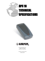
GPS 10 TECHNICAL SPECIFICATIONS Garmin International, Inc. 1200 E. 151st Street Olathe, KS 66062 USA 190-00516-00, Revision B February 2005 © Copyright 2005 Garmin Ltd. or its subsidiaries Garmin International, Inc. 1200 East 151st Street, Olathe, Kansas 66062, U.S.A. Tel. 913/397.8200 or 800/800.1020 Fax 913/397.8282 Garmin (Europe) Ltd. Unit 5, The Quadrangle, Abbey Park Industrial Estate, Romsey, SO51 9DL, U.K. Tel. 44/0870.8501241 Fax 44/0870.8501251 Garmin Corporation No. 68, Jangshu 2nd Road, Shijr, Taipei County, Taiwan Tel. 886/2.2642.9199 Fax 886/2.2642.9099 All rights reserved. Except as expressly provided herein, no part of this manual may be reproduced, copied, transmitted, disseminated, downloaded, or stored in any storage medium, for any purpose without the express prior written consent of Garmin. Garmin hereby grants permission to download a single copy of this manual onto a hard drive or other electronic storage medium to be viewed and to print one copy of this manual or of any revision hereto, provided that such electronic or printed copy of this manual must contain the complete text of this copyright notice and provided further that any unauthorized commercial distribution of this manual or any revision hereto is strictly prohibited. Information in this document is subject to change without notice. Garmin reserves the right to change or improve its products and to make changes in the content without obligation to notify any person or organization of such changes or improvements. Visit the Garmin Web site (www.garmin.com) for current updates and supplemental information concerning the use and operation of this and other Garmin products. Garmin and AutoLocate are registered trademarks of Garmin Ltd. or its subsidiaries and may not be used without express permission of Garmin. Web site address: www.garmin.com RECORD OF REVISIONS Revision A B 190-00516-00 Revision Date 12/10/04 02/01/05 Description Initial Release Revised and Redrawn GPS 10 Technical Specifications Page ii ECO # -29554 Rev. B TABLE OF CONTENTS 1 Introduction..................................................................................................................1 1.1 Cautions ............................................................................................................................................1 1.2 Limited Warranty ..............................................................................................................................2 1.3 Overview...........................................................................................................................................3 1.4 Features .............................................................................................................................................3 1.4.1 GPS 10 Wireless Receiver...................................................................................................................... 4 1.5 Technical Specifications ...................................................................................................................5 1.5.1 Physical Characteristics.......................................................................................................................... 5 1.5.1.1 Size ............................................................................................................................................... 5 1.5.1.2 Weight .......................................................................................................................................... 5 1.5.1.3 Color............................................................................................................................................. 5 1.5.1.4 Case Material................................................................................................................................ 5 1.5.2 Electrical Characteristics ........................................................................................................................ 5 1.5.2.1 Input Voltage................................................................................................................................ 5 1.5.2.2 Input Current ................................................................................................................................ 5 1.5.2.3 Battery .......................................................................................................................................... 5 1.5.2.4 Battery Charger ............................................................................................................................ 5 1.5.2.5 GPS Receiver Sensitivity.............................................................................................................. 5 1.5.3 Environmental Characteristics................................................................................................................ 5 1.5.3.1 Operating Temperature Range...................................................................................................... 5 1.5.3.2 Battery Charging Temperature Range .......................................................................................... 5 1.5.3.3 Storage Temperature .................................................................................................................... 5 1.5.4 GPS Performance ................................................................................................................................... 6 1.5.4.1 Receiver........................................................................................................................................ 6 1.5.4.2 Acquisition Times ........................................................................................................................ 6 1.5.4.3 Update Rate .................................................................................................................................. 6 1.5.4.4 Accuracy....................................................................................................................................... 6 1.5.5 Interfaces ................................................................................................................................................ 6 1.5.5.1 GPS 10 Electrical Characteristics ................................................................................................. 6 1.5.5.2 Garmin Interface........................................................................................................................... 6 1.5.5.3 GPS 10 Protocol ........................................................................................................................... 6 2 Mechanical Characteristics & Mounting...................................................................7 3 GPS 10 Software Interface..........................................................................................8 3.1 Received NMEA 0183 Sentences .....................................................................................................8 3.1.1 3.1.2 3.1.3 3.1.4 3.1.5 Almanac Information (ALM) ................................................................................................................. 8 Sensor Initialization Information (PGRMI)............................................................................................ 9 Sensor Configuration Information (PGRMC)......................................................................................... 9 Additional Sensor Configuration Information (PGRMC1)....................................................................10 Output Sentence Enable/Disable (PGRMO)..........................................................................................10 3.2 Transmitted NMEA 0183 Sentences...............................................................................................11 3.2.1 Sentence Transmission Rate ..................................................................................................................11 3.2.2 Transmitted Time ..................................................................................................................................12 3.2.3 Global Positioning System Almanac Data (ALM) ................................................................................12 3.2.4 Global Positioning System Fix Data (GGA)..........................................................................................12 3.2.5 GPS DOP and Active Satellites (GSA) .................................................................................................13 3.2.6 GPS Satellites in View (GSV) ...............................................................................................................13 3.2.7 Recommended Minimum Specific GPS/TRANSIT Data (RMC)..........................................................13 3.2.8 Track Made Good and Ground Speed (VTG)........................................................................................13 3.2.9 Geographic Position (GLL) ...................................................................................................................14 3.2.10 Estimated Error Information (PGRME).................................................................................................14 3.2.11 GPS Fix Data Sentence (PGRMF).........................................................................................................14 3.2.12 Sensor Status Information (PGRMT) ....................................................................................................14 3.2.13 3D velocity Information (PGRMV).......................................................................................................15 190-00516-00 GPS 10 Technical Specifications Page iii Rev. B 3.2.14 DGPS Beacon Information (PGRMB)...................................................................................................15 3.3 Baud Rate Selection ........................................................................................................................15 Appendix A: Earth Datums ............................................................................................16 Appendix B: Binary Phase Output Format...................................................................19 Appendix C: GPS 10 and Windows Serial Mouse Issue ..............................................23 Appendix D: Sensor Configuration Software................................................................25 Downloading the Sensor Configuration Software............................................................................................25 Selecting a Model.............................................................................................................................................25 Connecting to the Sensor .................................................................................................................................25 File Menu.........................................................................................................................................................26 Comm Menu ....................................................................................................................................................26 Config Menu ....................................................................................................................................................26 View Menu ......................................................................................................................................................27 Help Menu .......................................................................................................................................................27 Appendix E: Host System Considerations………………...…………………………..28 PIN Code…………………………………………………………..…………………………………………..28 LIST OF TABLES AND FIGURES Figure 1. GPS 10 Bottom Case Dimensions................................................................................................... 7 Figure 2. GPS 10 Operational Characteristics ................................................................................................ 7 Table 1: NMEA 0183 Output Sentence Order and Size ............................................................................... 11 Table 2: Characters per Second for Available Baud Rates........................................................................... 11 190-00516-00 GPS 10 Technical Specifications Page iv Rev. B 1 INTRODUCTION 1.1 CAUTIONS CAUTION The GPS system is operated by the government of the United States, which is solely responsible for its accuracy and maintenance. Although the GPS 10 is a precision electronic NAVigation AID (NAVAID), any NAVAID can be misused or misinterpreted, and therefore become unsafe. Use these products at your own risk. To reduce the risk, carefully review and understand all aspects of these Technical Specifications before using the GPS 10. When in actual use, carefully compare indications from the GPS to all available navigation sources including the information from other NAVAIDs, visual sightings, charts, etc. For safety, always resolve any discrepancies before continuing navigation. FCC Compliance The GPS 10 complies with Part 15 of the FCC interference limits for Class B digital devices FOR HOME OR OFFICE USE. These limits are designed to provide reasonable protection against harmful interference in a residential installation, and are more stringent than “outdoor” requirements. Operation of this device is subject to the following conditions: (1) This device may not cause harmful interference, and (2) this device must accept any interference received, including interference that may cause undesired operation. This equipment generates, uses and can radiate radio frequency energy and, if not installed and used in accordance with the instructions, may cause harmful interference to radio communications. However, there is no guarantee that interference will not occur in a particular installation. If this equipment does cause harmful interference to radio or television reception, which can be determined by turning the equipment off and on, the user is encouraged to try to correct the interference by one or more of the following measures: • Reorient or relocate the receiving antenna. • Increase the separation between the equipment and receiver. • Connect the equipment into an outlet on a circuit different from that to which the receiver is connected. • Consult the dealer or an experienced radio/TV technician for help. The GPS 10 does not contain any user-serviceable parts. Unauthorized repairs or modifications could result in permanent damage to the equipment, and void your warranty and your authority to operate this device under Part 15 regulations. 190-00516-00 GPS 10 Technical Specifications Page 1 Rev. B 1.2 LIMITED WARRANTY This Garmin product is warranted to be free from defects in materials or workmanship for one year from the date of purchase. Within this period, Garmin will at its sole option repair or replace any components that fail in normal use. Such repairs or replacement will be made at no charge to the customer for parts or labor, provided that the customer shall be responsible for any transportation cost. This warranty does not cover failures due to abuse, misuse, accident, or unauthorized alteration or repairs. THE WARRANTIES AND REMEDIES CONTAINED HEREIN ARE EXCLUSIVE AND IN LIEU OF ALL OTHER WARRANTIES EXPRESS OR IMPLIED OR STATUTORY, INCLUDING ANY LIABILITY ARISING UNDER ANY WARRANTY OF MERCHANTABILITY OR FITNESS FOR A PARTICULAR PURPOSE, STATUTORY OR OTHERWISE. THIS WARRANTY GIVES YOU SPECIFIC LEGAL RIGHTS, WHICH MAY VARY FROM STATE TO STATE. IN NO EVENT SHALL GARMIN BE LIABLE FOR ANY INCIDENTAL, SPECIAL, INDIRECT OR CONSEQUENTIAL DAMAGES, WHETHER RESULTING FROM THE USE, MISUSE, OR INABILITY TO USE THIS PRODUCT OR FROM DEFECTS IN THE PRODUCT. Some states do not allow the exclusion of incidental or consequential damages, so the above limitations may not apply to you. Garmin retains the exclusive right to repair or replace the unit or software or offer a full refund of the purchase price at its sole discretion. SUCH REMEDY SHALL BE YOUR SOLE AND EXCLUSIVE REMEDY FOR ANY BREACH OF WARRANTY. To obtain warranty service, contact your local Garmin authorized dealer or call Garmin Product Support at one of the numbers listed below for shipping instructions and an RMA tracking number. The unit should be securely packed with the tracking number clearly written on the outside of the package. The unit should then be sent, freight charges prepaid, to any Garmin warranty service station. A copy of the original sales receipt is required as the proof of purchase for warranty repairs. Garmin International, Inc. 1200 E 151st Street, Olathe, Kansas 66062 U.S.A. Tel. 913/397.8200 or 800/800.1020 Fax. 913/397.8282 Garmin (Europe) Ltd. Unit 5, The Quadrangle, Abbey Park Industrial Estate, Romsey, SO51 9DL U.K. Tel. 44/0870.8501241 Fax 44/0870.8501251 Online Auction Purchases: Products sold through online auctions are not eligible for rebates or other special offers from Garmin. Online auction confirmations are not accepted for warranty verification. To obtain warranty service, an original or copy of the sales receipt from the original retailer is required. Garmin will not replace missing components from any package purchased through an online auction. International Purchases: A separate warranty is provided by international distributors for units purchased outside the United States. This warranty is provided by the local in-country distributor and this distributor provides local service for your unit. Distributor warranties are only valid in the area of intended distribution. Units purchased in the United States or Canada must be returned to the Garmin service center in the United Kingdom, the United States, Canada, or Taiwan for service. 190-00516-00 GPS 10 Technical Specifications Page 2 Rev. B 1.3 OVERVIEW The GPS 10 product is a GPS receiver with WAAS capability, a rechargeable lithium-ion battery, integral magnetic base and Bluetooth wireless technology capability. Based on the proven technology found in other Garmin 12-channel GPS receivers, the GPS 10 tracks up to 12 satellites at a time while providing fast time-to-first-fix, one-second navigation updates, and low power consumption. This generation of GPS sensors adds the capability of FAA Wide Area Augmentation System (WAAS) differential GPS. The GPS 10’s far-reaching capability meets the sensitivity requirements of land navigation as well as the dynamics requirements of high-performance aircraft. The GPS 10 design uses the latest technology and high-level circuit integration to achieve superior performance while minimizing space and power requirements. All critical components of the system including the GPS RF/IF receiver hardware and the GPS digital baseband are designed and manufactured by Garmin to ensure the quality and capability of the GPS. The hardware capability combined with software intelligence makes the GPS 10 easy to integrate and use for laptop/tablet PC, PDA, and smart phone applications by incorporating a Class 2 Bluetooth module within the unit. The GPS 10 product is designed to withstand rugged operating conditions and is waterproof to IEC 60529 IPX7, immersion in 1 meter of water for 30 minutes. This complete GPS receiver requires no additional components to be supplied by an OEM or system integrator. An internal rechargeable lithium-ion battery and 12 VDC charging adapter are provided with the receiver. The only requirement is a clear view of the GPS satellites. Internal FLASH memory allows the GPS to retain critical data such as satellite orbital parameters, last-known position, date and time. End user interfaces such as keyboards and displays are the responsibility of the application designer. 1.4 FEATURES • Integrated Bluetooth (Class 2) wireless technology module for communication with a mobile device. • 12-channel GPS receiver tracks and uses up to 12 satellites for fast, accurate positioning and low power consumption. • Differential DGPS capability using real-time WAAS corrections yielding position errors of less than 3 meters. • Compact, rugged design ideal for applications with minimal space. Receiver position information can be displayed directly on a chartplotter or laptop/tablet PC, PDA, or smart phone with Bluetooth wireless technology capability. • User initialization is not required. Once installed, unit automatically produces navigation data after position fix is acquired. • User-configurable navigation mode (2-dimensional or 3-dimensional fix). • Configurable for binary format carrier phase data output. • FLASH-based program and non-volatile memory. New software revisions available through Web site download. Non-volatile memory does not require battery backup. • On-board rechargeable main power battery to maintain the real-time clock • The real-time clock can run for up to 2 months after the main battery enters a low battery mode. • Configurable parameters include expected position, current time and date, preferred position fix type (2D, 3D, or automatic), and velocity filter time constant (none, automatic, or your choice between 2 and 255 seconds). • Magnetic mount for attachment to ferrous surfaces. Velcro adhesive backed patch for nonmagnetic surfaces. • Includes 12 VDC Cigarette Lighter Charging Adapter. • Waterproof design allows continuous exposure to the prevailing weather conditions at most locations. • Auto Power On Mode: When in the Off mode and connected to a switched 12 V DC external power source, the GPS 10 automatically turns On when external power is turned on. (example: a cigarette lighter controlled by the vehicle ignition switch.) 190-00516-00 GPS 10 Technical Specifications Page 3 Rev. B 1.4.1 GPS 10 Wireless Receiver The GPS 10 uses Bluetooth wireless technology to interface with a mobile device (Computer/PDA) that is Bluetooth wireless technology enabled. Class 2 Bluetooth device with power control capability based on the Bluetooth System Specification, Version 1.1. The supported profile is Serial Profile (SSP). Accessories provided with the GPS 10: • Velcro Mounting Patch (Not shown) • 12 VDC Cigarette Lighter Charging Adapter (010-10412-00) 12 VDC Charging Adapter Optional Accessories: • Suction Cup Windshield Mount (010-10616-00) • 110-115 V AC Charging Adapter (010-10413-00) Suction Cup Mount AC Charging Adapter Power Plug Specifications for charging the GPS 10 from user provided power source: 5 VDC (Range 4.8 to 5.5 VDC @ 600 mA) Power Plug Dimensions 190-00516-00 GPS 10 Technical Specifications Page 4 Rev. B 1.5 TECHNICAL SPECIFICATIONS Specifications are subject to change without notice. 1.5.1 Physical Characteristics 1.5.1.1 Size 45 mm wide, 88 mm long and 19 mm in height. 1.5.1.2 Weight 80.0 grams 1.5.1.3 Color Black w/Gray Accents 1.5.1.4 Case Material Polycarbonate thermoplastic case that is waterproof to IEC 60529 IPX7 level (immersion in 1 meter of water for 30 minutes) 1.5.2 Electrical Characteristics 1.5.2.1 Input Voltage 4.8–6.5 V 1.5.2.2 Input Current 500mA @ 5.0 V 1.5.2.3 Battery • Capacity: 900 mAHr • Charging rate: • Operating time: Approx. 12 Hours with WAAS enabled. Approx. 3 Hrs 1.5.2.4 Battery Charger The included Cigarette Lighter Adapter (320-00187-00) can be used to charge the GPS 10’s internal battery or an AC Wall Charger (362-00028-00) can be purchased separately to charge the battery. • Input 10 to 30 V AC • Output 4.9 to 5.25 V DC @ 1.0 A 1.5.2.5 GPS Receiver Sensitivity -165 dBW minimum 1.5.3 Environmental Characteristics 1.5.3.1 Operating Temperature Range • -30°C to + 60°C Powered from external supply • -10°C to +60°C Powered by internal batteries 1.5.3.2 Battery Charging Temperature Range 5°C to 45°C (Outside this temperature range, battery charging is not possible) 1.5.3.3 Storage Temperature -40°C to +90°C 190-00516-00 GPS 10 Technical Specifications Page 5 Rev. B 1.5.4 GPS Performance 1.5.4.1 Receiver WAAS Enabled™; 12 parallel channel GPS receiver continuously tracks and uses up to 12 satellites to compute and update your position. 1.5.4.2 Acquisition Times • Reacquisition: Less than 2 seconds • Warm: Approx. 15 seconds (all data known) • Cold: Approx. 45 seconds (initial position, time, and almanac known; ephemeris unknown) • AutoLocate®: 5 minutes (almanac known; initial position and time unknown) • SkySearch: 5 minutes (no data known) 1.5.4.3 Update Rate 1 record per second 1.5.4.4 Accuracy • GPS Standard Positioning Service (SPS) Position: < 15 meters, 95% typical Velocity: 0.1 knot RMS steady state • WAAS Position: Velocity: • Dynamics: dynamics 1.5.5 < 3 meters, 95% typical 0.1 knot RMS steady state 999 knots velocity (only limited at altitude greater than 60,000 feet), 6g Interfaces 1.5.5.1 GPS 10 Electrical Characteristics • Communicate with Host Platform via Bluetooth Serial Profile • Typical Range: up to 32 feet (10 meters) 1.5.5.2 Garmin Interface Refer to the Garmin Device Interface Specification for specific information about the Garmin Protocol. The document is located on the Garmin Web site at http://www.garmin.com/support/ commProtocol.html. See also Appendix B: Binary Phase Output Format for additional information concerning access to raw pseudo-range and carrier phase data from the GPS 10. 1.5.5.3 GPS 10 Protocol • NMEA 0183 Version 2.0 or NMEA 0183 Version 2.30 (Version 2.0 is factory default, programmable by data field 7 of the PGRMC1 sentence described in Section 3.1.4 Additional Sensor Configuration Information (PGRMC1). • Available NMEA 0183 output sentences include GPALM, GPGGA, GPGSA, GPGSV, GPRMC, GPVTG, GPGLL, PGRME, PGRMF, PGRMT, PGRMV, and PGRMB (Garmin proprietary sentences). See Section 3.2 Transmitted NMEA 0183 Sentences for format descriptions. • Configuration and initialization is accomplished with NMEA 0183 input sentences. Allows initialization of information such as expected position, date, time, earth datum, and differential mode. See Section 3.1 Received NMEA 0183 Sentences for format descriptions. • Configurable for binary data output including GPS carrier phase data. 190-00516-00 GPS 10 Technical Specifications Page 6 Rev. B 2 MECHANICAL CHARACTERISTICS & MOUNTING The unit contains an integrated magnetic mount and a Velcro patch for mounting on non-ferrous surfaces. The following drawings show example geometry for mounting hardware in case you wish to design your own custom mount. Figure 1 shows the mounting footprint. Figure 2 shows operational characteristics of the GPS 10. Figure 1. GPS 10 Bottom Case Dimensions Figure 2. GPS 10 Operational Characteristics 190-00516-00 GPS 10 Technical Specifications Page 7 Rev. B 3 GPS 10 SOFTWARE INTERFACE The interface protocol design of the GPS 10 product is based on the National Marine Electronics Association’s NMEA 0183 ASCII interface specification. This standard is fully defined in NMEA 0183, Version 2.30. Copies may be obtained from NMEA, http://www.nmea.org/. In addition to the standard NMEA 0183 sentences, the GPS 10 may also be configured to transmit information over their serial interface using NMEA 0183 compliant Garmin proprietary sentences. These proprietary sentences begin with the characters, “$PGRM”, instead of the characters “$G” that are typical of the standard NMEA 0183 sentences. The characters “$P” indicate that the sentence is a proprietary implementation and the characters and “GRM” indicate that it is Garmin’s proprietary sentence. The letter (or letters) that follow the characters “$PGRM” uniquely identifies that particular Garmin proprietary sentence. It is also possible to configure the GPS 10 to transmit binary phase data information over their serial interface. See Appendix B: Binary Phase Output Format for details. The following sections describe the NMEA 0183 data format of each sentence transmitted and received by the GPS 10 product. 3.1 RECEIVED NMEA 0183 SENTENCES The following paragraphs define the sentences that can be received on the GPS sensor’s port. Null fields in the configuration sentence indicate no change in the particular configuration parameter. All sentences received by the GPS sensor must be terminated with <CR><LF>, the ASCII characters for carriage return (0D hexadecimal) and line feed (0A hexadecimal). The checksum *hh is used for parity checking data and is not required, but is recommended for use in environments containing high electromagnetic noise. It is generally not required in normal PC environments. When used, the parity bytes (hh) are the ASCII representation of the exclusive-or (XOR) sum of all the characters between the “$” and “*” characters, noninclusive. The hex representation must be a capital letter, such as 3D instead of 3d. Sentences may be truncated by <CR><LF> after any data field and valid fields up to that point will be acted on by the sensor. 3.1.1 Almanac Information (ALM) The $GPALM sentence can be used to initialize the GPS sensor’s stored almanac information in the unlikely event of non-volatile memory loss or after storing longer than six months without tracking GPS satellites. $GPALM,<1>,<2>,<3>,<4>,<5>,<6>,<7>,<8>,<9>,<10>,<11>,<12>,<13>,<14>,<15>*hh<CR><LF> <1> <2> <3> <4> <5> <6> <7> <8> <9> <10> <11> <12> <13> <14> <15> 190-00516-00 Total number of ALM sentences to be transmitted by the GPS sensor during almanac download. This field can be null or any number when sending almanac to the GPS sensor. Number of current ALM sentence. This field can be null or any number when sending almanac to the GPS sensor. Satellite PRN number, 01 to 32 GPS week number SV health, bits 17-24 of each almanac page Eccentricity Almanac reference time Inclination angle Rate of right ascension Root of semi major axis Omega, argument of perigee Longitude of ascension node Mean anomaly af0 clock parameter af1 clock parameter GPS 10 Technical Specifications Page 8 Rev. B 3.1.2 Sensor Initialization Information (PGRMI) The $PGRMI sentence provides information used to initialize the GPS sensor’s set position and time used for satellite acquisition. Receipt of this sentence by the GPS sensor causes the software to restart the satellite acquisition process. If there are no errors in the sentence, it will be echoed upon receipt. If an error is detected, the echoed PGRMI sentence will contain the current default values. Current PGRMI defaults (with the exception of the Receiver Command, which is a command rather than a mode) can also be obtained by sending $PGRMIE to the GPS sensor. $PGRMI,<1>,<2>,<3>,<4>,<5>,<6>,<7>*hh<CR><LF> <1> <2> <3> <4> <5> <6> <7> 3.1.3 Latitude, ddmm.mmm format (leading zeros must be transmitted) Latitude hemisphere, N or S Longitude, dddmm.mmm format (leading zeros must be transmitted) Longitude hemisphere, E or W Current UTC date, ddmmyy format Current UTC time, hhmmss format Receiver Command, A = Auto Locate, R = Unit Reset Sensor Configuration Information (PGRMC) The $PGRMC sentence provides information used to configure the GPS sensor’s operation. Configuration parameters are stored in non-volatile memory and retained between power cycles. The GPS sensor will echo this sentence upon its receipt if no errors are detected. If an error is detected, the echoed PGRMC sentence will contain the current default values. Current default values can also be obtained by sending $PGRMCE to the GPS sensor. $PGRMC,<1>,<2>,<3>,<4>,<5>,<6>,<7>,<8>,<9>,<10>,<11>,<12>,<13>,<14>*hh<CR><LF> <1> Fix mode, A = automatic, 2 = 2D exclusively (host system must supply altitude), 3 = 3D exclusively <2> Altitude above/below mean sea level, -1500.0 to 10000.0 meters <3> Earth datum index. If the user datum index (96) is specified, fields <4> through <8> must contain valid values. Otherwise, fields <4> through <8> must be null. Refer to Appendix A: Earth Datums for a list of earth datums and the corresponding earth datum index. <4> User earth datum semi-major axis, 6360000.000 to 6380000.000 meters (.001 meters resolution) <5> User earth datum inverse flattening factor, 285.0 to 310.0 (10-9 resolution) <6> User earth datum delta x earth centered coordinate, -5000.0 to 5000.0 meters (1 meter resolution) <7> User earth datum delta y earth centered coordinate, -5000.0 to 5000.0 meters (1 meter resolution) <8> User earth datum delta z earth centered coordinate, -5000.0 to 5000.0 meters (1 meter resolution) <9> Differential mode, A = automatic (output DGPS data when available, non-DGPS otherwise), D = differential exclusively (output only differential fixes) <10> NMEA 0183 Baud rate, 1 = 1200, 2 = 2400, 3 = 4800, 4 = 9600, 5 = 19200, 6 = 300, 7 = 600 <11> Velocity filter, 0 = No filter, 1 = Automatic filter, 2-255 = Filter time constant (e.g., 10 = 10 second filter) <12> Not used <13> Not used <14> Dead reckoning valid time 1-30 (sec) All configuration changes take effect after receipt of a valid value except baud rate. Baud rate change takes effect on the next power cycle or an external reset even. 190-00516-00 GPS 10 Technical Specifications Page 9 Rev. B 3.1.4 Additional Sensor Configuration Information (PGRMC1) The $PGRMC1 sentence provides additional information used to configure the GPS sensor operation. Configuration parameters are stored in non-volatile memory and retained between power cycles. The GPS sensor will echo this sentence upon its receipt if no errors are detected. If an error is detected, the echoed PGRMC1 sentence will contain the current default values. Current default values can also be obtained by sending $PGRMC1E to the GPS sensor. $PGRMC1,<1>,<2>,<3>,<4>,<5>,<6>,<7>,<8>,<9>,<10>,<11>,<12>*hh<CR><LF> <1> NMEA 0183 output time 1-900 (sec) <2> Binary Phase Output Data, 1 = Off, 2 = On. <3> Automatic Position Averaging when Stopped, 1 = Off, 2 = On <4> No Effect (DGPS beacon frequency – 0.0, 283.5 – 325.0 kHz in 0.5 kHz steps) <5> No Effect (DGPS beacon bit rate – 0, 25, 50, 100, or 200 bps) <6> No Effect (DGPS beacon scanning, 1 = Off, 2 = On) <7> NMEA 0183 version 2.30 mode indicator, 1 = Off, 2 = On <8> DGPS mode, W = WAAS Only, N = None (DGPS disabled) <9> Power Save Mode for GPS, P = Power Save mode, N = Normal <10> Adaptive Transmission Enabled, 1 = Off, 2 = On <11> Auto Power Off, 1 = Off, 2 = On <12> Power On with External Charger, 1 = Off, 2 = On Configuration changes take effect immediately, with the exception of Binary Phase Output Data, which takes effect on the next power cycle or a reset event. A reset can be commanded by sending the sentence “$PGRMI,,,,,,,R” (refer to Section 3.1.2 Sensor Initialization Information (PGRMI)). If the GPS sensor is in the Binary data mode, it is necessary to send the following eight-byte data stream to temporarily change the data format to NMEA 0183. Then follow by sending a PGRMC1 sentence that turns off the Binary Phase Output Data format: 10 0A 02 26 00 CE 10 03 (Hexadecimal) 3.1.5 Output Sentence Enable/Disable (PGRMO) The $PGRMO sentence provides the ability to enable and disable specific output sentences. The following sentences are enabled at the factory: GPGGA, GPGSA, GPGSV, GPRMC, and PGRMT. $PGRMO,<1>,<2>*hh<CR><LF> <1> <2> Target sentence description (e.g., PGRMT, GPGSV, etc.) Target sentence mode, where: 0 = disable specified sentence 1 = enable specified sentence 2 = disable all output sentences 3 = enable all output sentences (except GPALM) 4 = restore factory default output sentences The following notes apply to the PGRMO input sentence: 1. If the target sentence mode is ‘2’ (disable all), ‘3’ (enable all), or ‘4’ (restore defaults), the target sentence description is not checked for validity. In this case, an empty field is allowed (e.g., $PGRMO,,3), or the mode field may contain from 1 to 5 characters. 2. If the target sentence mode is ‘0’ (disable) or ‘1’ (enable), the target sentence description field must be an identifier for one of the sentences that can be output by the GPS sensor. 3. If either the target sentence mode field or the target sentence description field is not valid, the PGRMO sentence will have no effect. 4. $PGRMO,GPALM,1 will cause the GPS sensor to transmit all stored almanac information. All other NMEA 0183 sentence transmission will be suspended temporarily. 5. $PGRMO,,G will cause the COM port to change to Garmin Data Transfer format for the duration of the power cycle. The Garmin mode is required for GPS 10 series product software updates. 190-00516-00 GPS 10 Technical Specifications Page 10 Rev. B . 3.2 TRANSMITTED NMEA 0183 SENTENCES The subsequent paragraphs define the sentences that can be transmitted by the GPS 10. 3.2.1 Sentence Transmission Rate Sentences are transmitted with respect to the user selected baud rate. The GPS sensor will transmit each sentence (except where noted in particular transmitted sentence descriptions) at a periodic rate based on the user selected baud rate and user selected output sentences. The GPS sensor will transmit the selected sentences contiguously. The length of the transmission can be determined by the following equation and Tables 2 and 3: length of transmission = total characters to be transmitted --------------------------------------------characters transmitted per second Sentence Output by Default? Maximum Characters ✔ GPRMC 74 ✔ GPGGA 82 ✔ GPGSA 66 ✔ GPGSV 70 ✔ PGRME 35 GPGLL 44 GPVTG 42 PGRMV 32 PGRMF 82 ✔ PGRMB 40 PGRMT Once per minute 50 Table 1: NMEA 0183 Output Sentence Order and Size Baud Characters per Second 300 30 600 60 1200 120 2400 240 4800 480 9600 960 19200 1920 38400 3840 Table 2: Characters per Second for Available Baud Rates The maximum number of fields allowed in a single sentence is 82 characters including delimiters. Values in the table include the sentence start delimiter character “$” and the termination delimiter <CR><LF>. The factory set defaults will result in a once per second transmission at the NMEA 0183 specification transmission rate of 4800 baud. Regardless of the selected baud rate, the information transmitted by the GPS sensor is referenced to the one-pulse-per-second output pulse immediately preceding the GPRMC sentence, or whichever sentence is output first in the burst (see Table 2 above). 190-00516-00 GPS 10 Technical Specifications Page 11 Rev. B 3.2.2 Transmitted Time The GPS sensor outputs UTC (Coordinated Universal Time) date and time of day in the transmitted sentences. Before the initial position fix, the on-board clock provides the date and time of day. After the initial position fix, the date and time of day are calculated using GPS satellite information and are synchronized with the one-pulse-per-second output. The GPS sensor uses information obtained from the GPS satellites to add or delete UTC leap seconds and correct the transmitted date and time of day. The transmitted date and time of day for leap second correction follow the guidelines in National Institute of Standards and Technology Special Publication 432 (Revised 1990). This document is for sale by the Superintendent of Documents, U.S. Government Printing Office, Washington, D.C., 20402, U.S.A. When a positive leap second is required, one second is inserted at the beginning of the first hour (0h 0m 0s) of the day that the positive leap is occurring. The minute containing the leap second is 61 seconds long. The GPS sensor would have transmitted this information for the leap second added December 31, 1998 as follows: $GPRMC,235959,A,3851.3651,N,09447.9382,W,000.0,221.9,071103,003.3,E*69 $GPRMC,000000,A,3851.3651,N,09447.9382,W,000.0,221.9,081103,003.3,E*67 $GPRMC,000000,A,3851.3651,N,09447.9382,W,000.0,221.9,081103,003.3,E*67 $GPRMC,000001,A,3851.3651,N,09447.9382,W,000.0,221.9,081103,003.3,E*66 If a negative leap second should be required, one second will be deleted at the end of some UTC month. The minute containing the leap second will be only 59 seconds long. In this case, the GPS sensor will not transmit the time of day 0h 0m 0s (the “zero” second) for the day from which the leap second is removed. $GPRMC,235959,A,3851.3650,N,09447.9373,W,000.0,000.0,111103,003.3,E*69 $GPRMC,000001,A,3851.3650,N,09447.9373,W,000.0,000.0,121103,003.3,E*6A $GPRMC,000002,A,3851.3650,N,09447.9373,W,000.0,000.0,121103,003.3,E*69 3.2.3 Global Positioning System Almanac Data (ALM) Almanac sentences are not normally transmitted. Almanac transmission can be initiated by sending the GPS sensor a $PGRMO,GPALM,1 command. Upon receipt of this command, the GPS sensor will transmit available almanac information on GPALM sentences. During the transmission of almanac sentences, other NMEA 0183 data output will be suspended temporarily. $GPALM,<1>,<2>,<3>,<4>,<5>,<6>,<7>,<8>,<9>,<10>,<11>,<12>,<13>,<14>,<15>*hh<CR><LF> <field information> can be found in Section 3.1.1 Almanac Information (ALM). 3.2.4 Global Positioning System Fix Data (GGA) $GPGGA,<1>,<2>,<3>,<4>,<5>,<6>,<7>,<8>,<9>,M,<10>,M,<11>,<12>*hh<CR><LF> <1> <2> <3> <4> <5> <6> <7> <8> <9> <10> <11> <12> 190-00516-00 UTC time of position fix, hhmmss format Latitude, ddmm.mmmm format (leading zeros will be transmitted) Latitude hemisphere, N or S Longitude, dddmm.mmmm format (leading zeros will be transmitted) Longitude hemisphere, E or W GPS quality indication, 0 = fix not available, 1 = Non-differential GPS fix available, 2 = Differential GPS (DGPS) fix available, 6 = Estimated Number of satellites in use, 00 to 12 (leading zeros will be transmitted) Horizontal dilution of precision, 0.5 to 99.9 Antenna height above/below mean sea level, -9999.9 to 99999.9 meters Geoidal height, -999.9 to 9999.9 meters Differential GPS (RTCM SC-104) data age, number of seconds since last valid RTCM transmission (null if not an RTCM DGPS fix) Differential Reference Station ID, 0000 to 1023 (leading zeros will be transmitted, null if not an RTCM DGPS fix) GPS 10 Technical Specifications Page 12 Rev. B 3.2.5 GPS DOP and Active Satellites (GSA) $GPGSA,<1>,<2>,<3>,<3>,<3>,<3>,<3>,<3>,<3>,<3>,<3>,<3>,<3>,<3>,<4>,<5>,<6>*hh<CR><LF> <1> <2> <3> <4> <5> <6> 3.2.6 Mode, M = manual, A = automatic Fix type, 1 = not available, 2 = 2D, 3 = 3D PRN number, 01 to 32, of satellite used in solution, up to 12 transmitted (leading zeros will be transmitted) Position dilution of precision, 0.5 to 99.9 Horizontal dilution of precision, 0.5 to 99.9 Vertical dilution of precision, 0.5 to 99.9 GPS Satellites in View (GSV) $GPGSV,<1>,<2>,<3>,<4>,<5>,<6>,<7>,...<4>,<5>,<6>,<7>*hh<CR><LF> <1> <2> <3> <4> <5> <6> <7> Total number of GSV sentences to be transmitted Number of current GSV sentence Total number of satellites in view, 00 to 12 (leading zeros will be transmitted) Satellite PRN number, 01 to 32 (leading zeros will be transmitted) Satellite elevation, 00 to 90 degrees (leading zeros will be transmitted) Satellite azimuth, 000 to 359 degrees, true (leading zeros will be transmitted) Signal to noise ratio (C/No) 00 to 99 dB, null when not tracking (leading zeros will be transmitted) NOTE: Items <4>,<5>,<6>, and <7> repeat for each satellite in view to a maximum of four (4) satellites per sentence. Additional satellites in view information must be sent in subsequent bursts of NMEA 0183 data. These fields will be null if unused. 3.2.7 Recommended Minimum Specific GPS/TRANSIT Data (RMC) $GPRMC,<1>,<2>,<3>,<4>,<5>,<6>,<7>,<8>,<9>,<10>,<11>,<12>*hh<CR><LF> <1> <2> <3> <4> <5> <6> <7> <8> <9> <10> <11> <12> 3.2.8 UTC time of position fix, hhmmss format Status, A = Valid position, V = NAV receiver warning Latitude, ddmm.mmmm format (leading zeros will be transmitted) Latitude hemisphere, N or S Longitude, dddmm.mmmm format (leading zeros will be transmitted) Longitude hemisphere, E or W Speed over ground, 000.0 to 999.9 knots (leading zeros will be transmitted) Course over ground, 000.0 to 359.9 degrees, true (leading zeros will be transmitted) UTC date of position fix, ddmmyy format Magnetic variation, 000.0 to 100.0 degrees (leading zeros will be transmitted) Magnetic variation direction, E or W (westerly variation adds to true course) Mode indicator (only output if NMEA 0183 version 2.30 active), A = Autonomous, D = Differential, E = Estimated, N = Data not valid Track Made Good and Ground Speed (VTG) $GPVTG,<1>,T,<2>,M,<3>,N,<4>,K,<5>*hh<CR><LF> <1> <2> <3> <4> <5> 190-00516-00 True course over ground, 000 to 359 degrees (leading zeros will be transmitted) Magnetic course over ground, 000 to 359 degrees (leading zeros will be transmitted) Speed over ground, 000.0 to 999.9 knots (leading zeros will be transmitted) Speed over ground, 0000.0 to 1051.8 kilometers per hour (leading zeros will be transmitted) Mode indicator (only output if NMEA 0183 version 2.30 active), A = Autonomous, D = Differential, E = Estimated, N = Data not valid GPS 10 Technical Specifications Page 13 Rev. B