1
Real-time Z Supplement
Supplement to Z-12 Receiver Operating Manual
Covering
Real-Time Z Functions
Real-time Z Supplement
Supplement to Z-12 Receiver Operating Manual
Ashtech® Document Number 600292 Revision C
Publication Date September 1996
© Copyright 1995,1996 Ashtech, Inc.
All rights reserved. No part of this publication may be reproduced, stored in a retrieval system, or
transmitted in any form or by any means, electronic, mechanical photocopying, recording, or otherwise, without the prior written permission of Ashtech, Inc. Further, this publication and features
described herein are subject to change without notice.
For further information on translations and distribution outside the U.S.A., please contact Ashtech, Inc.
NO PATENT LIABILITY IS ASSUMED WITH RESPECT TO THE USE OF INFORMATION
CONTAINED HEREIN. WHILE EVERY PRECAUTION HAS BEEN TAKEN IN THE PREPARATION OF THIS PUBLICATION, ASHTECH ASSUMES NO RESPONSIBILITY FOR
ERRORS OR OMISSIONS. NOR IS ANY LIABILITY ASSUMED FOR DAMAGES RESULTING FROM THE USE OF THE INFORMATION CONTAINED HEREIN.
Trademarks used herein are the property of the respective companies.
Printed in the United States of America.
Ashtech, Inc.
1170 Kifer Road
Sunnyvale CA 94086
Customer Support
Voice
FAX
BBS
1-800-229-2400 (U.S. only)
408-524-1600
408-524-1500
408-524-1527
Real-time Z Supplement
FCC USER'S MANUAL STATEMENT
Class A Verification Requirements
This equipment has been tested and found to comply with the limits of Class A digital device, pursuant to Part 15 of the FCC rules. These limits are designed to provide a reasonable protection
against harmful interference in a residential installation. This equipment generates, uses, and can
radiate radio frequency energy and, if not installed and used in accordance with the instructions,
may cause harmful interference to radio communications. However, there is no guarantee that
interference will not occur in a particular installation. If this equipment does cause harmful interference to radio or television reception, which can be determined by turning the equipment off
and on, the user is encouraged to try to correct the interference by one or more of the following
measures:
•
•
•
Reorient or relocate the receiving antenna.
Increase the separation between the equipment and receiver.
Connect the equipment into an outlet on a circuit different from that to which the
receiver is connected.
•Consult the dealer or an experienced radio/TV technician for help.
Shielded cables and I/O cords must be used for this equipment to comply with the relevant FCC
regulations.
Changes or modifications not expressly approved in writing by Ashtech may void the user's
authority to operate this equipment.
INDUSTRY CANADA STATEMENT
This device complies with RSS-210 of Industry Canada. Operation is subject to the following
two conditions: (1) this device may not cause interference, and (2) this device must accept any
interference, including interference that may cause undesired operation of the device.
Real-time Z Supplement
FOREWORD
This document is intended to be used in conjunction with the Z-12 Receiver Operating Manual,
Ashtech document 600224 Rev. B. You should first refer to this manual to become familiar with
the basic Z-12 receiver operation and control.
The Real-time Z functions described in this supplement are in addition to or at variance with the
functions described in the Z-12 Receiver Operating Manual.
All the system components described herein have been certified for operation by the Federal
Communications Commission (FCC).
Conventions when using this manual are:
Receiver keys are denoted by square brackets. For example, the enter key on the receiver is shown
as [e] in this supplement.
Receiver messages are shown in all capital letters. For example, the Phase Differential Subscreen
of Screen 4 is given as PHASE DIF.
Real-time Z Supplement
CONTENTS
INTRODUCTION .............................................................................................................. 1
Principles of Carrier Phase Differential GPS................................................................. 1
On-the-Fly Ambiguity Resolution ................................................................................. 1
Fast Carrier Phase Differential....................................................................................... 1
Vector Processing and Reverse Vector Processing........................................................ 2
REAL-TIME Z SYSTEM OVERVIEW ............................................................................ 2
QUICK START GUIDE..................................................................................................... 4
Base Station Setup (DBEN) ........................................................................................... 4
Rover Station Setup (DBEN) ......................................................................................... 5
RTCM-RTK Carrier Phase Differential (CPD) Setup ................................................... 6
EQUIPMENT SETUP ........................................................................................................ 8
Base Station.................................................................................................................... 9
Rover Station.................................................................................................................. 9
RECEIVER CONFIGURATION ..................................................................................... 10
Check the Options ........................................................................................................ 10
Reset the Z-12 Receivers ............................................................................................. 12
Set Up the Base Station................................................................................................ 13
Enter Site ID................................................................................................................. 13
Set Up the Radio .......................................................................................................... 14
Enter the Base Station Coordinates............................................................................. 16
Save the Setup .............................................................................................................. 18
Set Up the Rover Station.............................................................................................. 18
Set Up the Radio .......................................................................................................... 18
Set the GPS Receiver in CPD Rover Mode ................................................................. 21
High Speed Solution Computation .............................................................................. 21
Save the Setup Parameters ........................................................................................... 22
ROVER SOLUTION MONITOR .................................................................................... 23
Screen 2........................................................................................................................ 23
Screen 20...................................................................................................................... 26
Position Information .................................................................................................... 28
PNAV Solution Status ................................................................................................. 28
Screen 5........................................................................................................................ 31
CPD Phase Residuals ................................................................................................... 31
DATA LINK MONITOR ................................................................................................. 32
Base Screen 5 ............................................................................................................... 32
Rover Screen 5 ............................................................................................................. 33
CPD SOLUTION STORAGE AND UTILIZATION ...................................................... 35
Solution Storage ........................................................................................................... 35
Vector Solution Storage ............................................................................................... 35
Real-time Solution Output ........................................................................................... 36
TROUBLESHOOTING.................................................................................................... 37
Rover doesn’t show Screen 20..................................................................................... 37
Base doesn’t show Screen 5 CPD Data Link Status page............................................ 37
Real-time Z Supplement
Base CPD Data Link Status page doesn’t show PRN numbers ................................... 37
Base beeps and Screen 4 position flashes .................................................................... 37
Base data radio status light isn’t blinking every second .............................................. 37
Rover data radio status light isn’t blinking every second ............................................ 37
Base station status on Screen 5 is not “00000” ............................................................ 38
Position is not updating on rover Screen 20 ................................................................ 38
Screen 20 doesn’t update every second or beeps and flashes OLD............................. 38
Screen 20 only shows float solution ............................................................................ 38
Real-time Z solutions are not being stored in the rover ............................................... 38
SYSTEM PERFORMANCE OPTIMIZATION .............................................................. 39
CPD Solution Parameters............................................................................................. 39
Dynamics ..................................................................................................................... 39
Multipath...................................................................................................................... 39
Initialization ................................................................................................................. 39
Fast CPD ...................................................................................................................... 40
Base Position................................................................................................................ 40
Ambiguity Fix Mode.................................................................................................... 40
Update Rate.................................................................................................................. 41
DBEN Message Interval .............................................................................................. 41
Base Station Elevation Mask ....................................................................................... 41
Radio Parameters ......................................................................................................... 42
Line-of-Sight Transmission ......................................................................................... 42
Data Transmission Rate ............................................................................................... 42
Sensitivity..................................................................................................................... 42
ERROR SOURCES OF CARRIER PHASE DIFFERENTIAL GPS .............................. 43
Radio Link Dropout ..................................................................................................... 43
GPS Signal Multipath .................................................................................................. 43
Satellite Geometry........................................................................................................ 43
Maintaining Lock to the Satellites ............................................................................... 43
Selective Availability................................................................................................... 43
MESSAGE CONTROL .................................................................................................... 44
REVERSE VECTOR PROCESSING .............................................................................. 45
Equipment Setup .......................................................................................................... 45
RVP Rover Setup ......................................................................................................... 45
RVP Base Setup ........................................................................................................... 45
Solution Monitoring..................................................................................................... 46
Solution Output and Data Storage ............................................................................... 46
APPENDIX A. DATA RADIO DEFAULT PARAMETERS ........................................ 47
Real-time Z Supplement
LIST OF FIGURES
Figure 1
Figure 2
Figure 3
Figure 4
Figure 5
Figure 6
Figure 7
Figure 8
Figure 9
Figure 10
Figure 11
Figure 12
Figure 13
Figure 14
Figure 15
Figure 16
Figure 17
Figure 18
Figure 19
Figure 20
Figure 21
Figure 22
Figure 23
Figure 24
Figure 25
Figure 26
Figure 27
Figure 28
Figure 29
Figure 30
Figure 31
Typical Real-Time Z Base Station . . . . . . . . . . . . . . . . . . . . . . . . . . . . . . . . . 2
Typical Real-time Z Rover Station . . . . . . . . . . . . . . . . . . . . . . . . . . . . . . . . . 4
Typical RTCM-RTK Configuration . . . . . . . . . . . . . . . . . . . . . . . . . . . . . . . . 7
Screen 0 . . . . . . . . . . . . . . . . . . . . . . . . . . . . . . . . . . . . . . . . . . . . . . . . . . . . . 10
Screen 4 . . . . . . . . . . . . . . . . . . . . . . . . . . . . . . . . . . . . . . . . . . . . . . . . . . . . . 11
Screen 4 Subcommands Subscreen . . . . . . . . . . . . . . . . . . . . . . . . . . . . . . . . 11
Screen 4, Configuration Identification Display . . . . . . . . . . . . . . . . . . . . . . . 12
Screen 9 - Site and Session Control. . . . . . . . . . . . . . . . . . . . . . . . . . . . . . . . 13
Screen 4, Modem Setup Menu. . . . . . . . . . . . . . . . . . . . . . . . . . . . . . . . . . . . 14
Screen 4, Modem Setup Subscreen . . . . . . . . . . . . . . . . . . . . . . . . . . . . . . . . 15
Screen 4, Carrier Phase Mode Selection . . . . . . . . . . . . . . . . . . . . . . . . . . . . 16
Screen 4, This Station Coordinates Subscreen . . . . . . . . . . . . . . . . . . . . . . . 17
Screen 4, Subcommands Menu . . . . . . . . . . . . . . . . . . . . . . . . . . . . . . . . . . . 18
Screen 4, Modem Setup Menu. . . . . . . . . . . . . . . . . . . . . . . . . . . . . . . . . . . . 19
Screen 4, Modem Setup Subscreen . . . . . . . . . . . . . . . . . . . . . . . . . . . . . . . . 20
Screen 4, Carrier Phase Mode Selection Subcreen . . . . . . . . . . . . . . . . . . . . 21
Screen 4, Receiver Control . . . . . . . . . . . . . . . . . . . . . . . . . . . . . . . . . . . . . . 22
Screen 4, Subcommands Subscreen . . . . . . . . . . . . . . . . . . . . . . . . . . . . . . . 23
Screen 2, Page 1. . . . . . . . . . . . . . . . . . . . . . . . . . . . . . . . . . . . . . . . . . . . . . . 24
Screen 2, Page 2. . . . . . . . . . . . . . . . . . . . . . . . . . . . . . . . . . . . . . . . . . . . . . . 24
Screen 2, Page 3. . . . . . . . . . . . . . . . . . . . . . . . . . . . . . . . . . . . . . . . . . . . . . . 25
Screen 20, Page 1. . . . . . . . . . . . . . . . . . . . . . . . . . . . . . . . . . . . . . . . . . . . . . 26
Screen 20, Page 2. . . . . . . . . . . . . . . . . . . . . . . . . . . . . . . . . . . . . . . . . . . . . . 26
Screen 20, Page 3. . . . . . . . . . . . . . . . . . . . . . . . . . . . . . . . . . . . . . . . . . . . . . 27
Screen 20, Page 4. . . . . . . . . . . . . . . . . . . . . . . . . . . . . . . . . . . . . . . . . . . . . . 27
Screen 20, Page 5. . . . . . . . . . . . . . . . . . . . . . . . . . . . . . . . . . . . . . . . . . . . . . 28
Screen 5, Page 3 - Phase Residuals . . . . . . . . . . . . . . . . . . . . . . . . . . . . . . . . 31
Screen 5, Page 3 - CPD Data Link Status for Base . . . . . . . . . . . . . . . . . . . . 33
Screen 4, Solution Parameters Selection Subscreen . . . . . . . . . . . . . . . . . . . 39
Carrier Phase Initialization . . . . . . . . . . . . . . . . . . . . . . . . . . . . . . . . . . . . . . 41
Screen 4, Messages Transmitting/Receiving Subscreen . . . . . . . . . . . . . . . . 44
7
Real-time Z Supplement
INTRODUCTION
Principles of Carrier Phase Differential GPS
The fundamental concept for any differential GPS system is to utilize the GPS measurement data
from a stationary GPS receiver at a known site (base station) to correct the errors in the measurement data of a GPS receiver at an unknown site (remote station). The GPS measurement data
transferred from the base station to the rover station can be either pseudo-range measurements,
carrier phase measurements or a combination of both. They can be in either raw data format or in
a specific correction format. For real-time differential GPS operation, this data is transferred via a
radio link.
The most common real-time differential GPS system uses a standard pseudo-range correction format called RTCM. The pseudo-range differential GPS can achieve from several meters down to a
sub-meter level of accuracy. To achieve accuracy down to centimeter level, the carrier phase data
must be used as well. A differential GPS system which uses the pseudo-range and carrier phase
measurement data is called Carrier Phase Differential (CPD) GPS.
Ashtech's Real-time Z system operates in CPD mode. The pseudo-range and carrier phase measurement data are transmitted from the base station to the rover station in a differential message.
These messages can be one of two kinds: DBEN or RTCM-RTK. This allows the rover station to
com
The Real-time Z system utilizes Ashtech's PNAV data processing engine. It processes the raw
measurement data from both base receiver and the rover in double difference form. Double difference processing is widely used in post-processing geodetic surveying software. It can achieve the
ultimate differential GPS accuracy - centimeter to millimeter level.
On-the-Fly Ambiguity Resolution
The most important feature of the Real-time Z system is its ability to resolve the cycle integer
ambiguities of the carrier phase measurements while the rover station is moving, thus the term
“on-the-fly” is used. With a PDOP less than two and five or more common satellites in view of
the base and rover stations, the Real-time Z system can achieve centimeter-level accuracy very
quickly, typically in less than a minute.
Fast Carrier Phase Differential
Another important feature of the Real-time Z system is the Fast CPD algorithm which reduces the
position solution latency, or delay.
Whether it is pseudo-range or carrier phase differential GPS, the most accurate solution is
obtained by processing the matched time-tag data from both the base station and the rover station.
This is not a problem in post-processing, since all of the raw data is recorded in the files. For realtime applications using the carrier phase differential (CPD) technique, the position solution could
be delayed up to 2 seconds. This is due to the extra data processing required and the latency of the
radio data link. While this delay may be acceptable for some applications such as static point surveying, it may not be acceptable for certain vehicle navigation and kinematic surveying applications.
To reduce the position solution latency, a Fast CPD algorithm has been implemented in the
receiver. It utilizes the differential correction scheme, which is commonly used in the pseudorange differential GPS, as well as an optimized data processing scheme to reduce the CPD solu1
Real-time Z Supplement
tion delay to less than a quarter second.
Vector Processing and Reverse Vector Processing
The most commonly used real-time differential GPS operation is to place one receiver at a known
position to serve as the base station. The base station transmits its raw measurement data over a
radio link. Multiple rover stations receive the raw measurement data from the base station and
compute their positions more accurately using this data. This operational mode is widely used in
vehicle navigation, and in land and aerial surveying.
However, the Real-time Z system is not constrained to operate in this mode alone. For applications such as robot monitoring and remote machine control, you may want to know the rover's
position at the base station. This is called Reverse Vector Processing (RVP). When the Real-time
Z system is configured in RVP mode, the raw measurement data from the rover station is transmitted. The base station, which is placed at a known site, receives the data from the rover station
and computes the rover's position.
REAL-TIME Z SYSTEM OVERVIEW
This chapter describes the hardware configuration for the Real-time Z system. The system is
divided into a base station and a rover station. In the discussion throughout this supplement the
terms “rover” and “remote” are commonly interchanged. These terms both refer to the station at
which the position is to be determined.
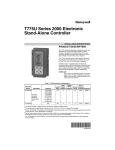
Base Station Configuration
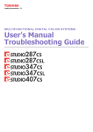
Figure 1 shows the configuration of a typical base station.
Figure 1 Typical Real-Time Z Base Station
Ashtech part numbers are shown for all the major components. Check your equipment to verify
2
Real-time Z Supplement
that you have all these items. The low-power Z-12 receiver, the key component of the Real-time Z
base system, requires a power source capable of providing 10-32 volts DC at 1.5 amps. The power
source shown in Figure 1 is a standard 12 volt, 8 amp-hour Ashtech battery.
Caution: Since the battery life is limited to about 8 hours of operation, it is recommended
that you use another power source for longer base station operation.
The Z-12 receiver tracks the GPS satellites by using an antenna which is mounted in a location
with good visibility to the whole sky. This antenna is of high quality, designed to lessen the effect
of multipath errors.
Caution: Make sure to mount the GPS antenna away from any large obstructions. Also, do
not mount the GPS antenna near any metal objects, since these objects will reflect the GPS
satellite signals causing multipath errors. Mounting the antenna higher will usually reduce
the multipath effect.
A base radio is used to transmit the GPS measurements from the base station to the rover station.
One of the Z-12 receiver's RS-232 serial ports is connected to the base radio to transfer its measurement data to the radio for transmission. Note that the base radio is also powered by this cable
via the Z-12 receiver's power supply.
The base radio draws 0.8 amps at 10-15 volts and provides 2 watts of RF output. However, the
supplied base station radio also has a 35-watt amplifier which allows data to be transmitted over
longer distances. This amplifier must be powered by a source capable of delivering 10-15 volts at
10 amps.
Caution: It is recommended that you use a heavy-duty power source, such as a car battery,
for longer base station operation.
Caution: It is NOT recommended that you power the Z-12 and base radio amplifier with the
same power source.
The base station radio shown in Figure 1 operates in the 450 MHz to 470 MHz frequency range
(UHF). Since UHF communication requires line-of-sight between the base and rover receivers,
the base radio antenna should be mounted as high as possible to allow the rover station to receive
the GPS measurements from the base station at longer distances. However, this needs to be balanced with reasonably short radio antenna cables, due to the relatively high cable loss at UHF frequencies. A length of 15 feet is used for the Ashtech base radio antenna cable.
Note that co-locating the base radio antenna and GPS antenna will not cause any interference
problems since they operate at different frequencies (UHF versus L-band). Detailed specifications for the base radio and its amplifier are given in the Base Radio Manual.
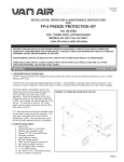
Rover Station Configuration
The rover station can be utilized in various configurations, including man-portable or vehicle
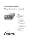
mount systems. A typical rover station setup is depicted in Figure 2.
3
Real-time Z Supplement
Figure 2 Typical Real-time Z Rover Station
Ashtech part numbers are shown for all the major components in this figure. Check your equipment to verify that you have all these items. The low-power Z-12 receiver is the key component of
the Real-time Z rover system. It requires a power source capable of providing 10-32 volts, DC at
1.5 amps.
A rover radio is used to receive the GPS measurements transmitted from the base station. One of
the Z-12 receiver's RS-232 serial ports is connected to the rover radio to receive the DBEN messages from the radio. The rover radio requires 10-15 volts at 0.1 amps. Figure 1 shows a standard
Ashtech 12-volt 8 amp-hour battery powering both the Z-12 receiver and rover radio.
QUICK START GUIDE
This chapter shows you how to get your Real-time Z system operating within a few minutes. The
chapter is divided into two sections. The first section guides you through differential setup using
Ashtech's proprietary DBEN message. The second section guides you through differential setup
using the new RTCM-RTK Type 18/19 messages.
Base Station Setup (DBEN)
1.
Set up and level the GPS antenna tripod over a known point with an unobstructed view of
the sky. Connect the GPS antenna to the Real-time Z receiver. Connect the UHF
antenna to the data radio. Connect the data radio's serial port to Port 2 of the
Real-time Z receiver. Connect the power cables to the Real-time Z receiver and
data radio.
4
Real-time Z Supplement
2.
Turn on the Real-time Z receiver. If the receiver settings have been changed from the factory default settings, you may restore the default settings by pressing down [C]
while switching the receiver on. Hold down [C] until the internal test message
appears. Release [C] and press the YES key [8]. After the internal test completes, press any key to continue the power-on sequence.
3.
The Skysearch screen (Screen 0) will be displayed after turning the unit on. Wait until four
or more channels display LK, which indicates that the GPS satellite signal has
been locked on. This should take less than a minute. View the position screen by
pressing [2]. Because the almanac information is erased during the internal test,
it may take up to four minutes before the first position is displayed. If at any
time the display's backlighting turns off, press any key to turn it back on.
4.
Press [4] to view the mode control screen. Press [e] and move the blinking cursor to
PHASE DIF using the arrow keys. Press [e] again to view the Carrier Phase
Mode Selection subscreen. Press [+] to change the mode from DISABLED to
BASE.
5.
If you know the WGS-84 coordinates where the base station is located, select THIS
COORDINATES and press [1]. Enter the latitude, longitude, and altitude using
the degrees:minutes:seconds format. If the coordinates are known in
degrees:minutes format, enter them on the first line of Screen 4. Measure and
enter the slant distance and antenna radius. Press [e] to enter the coordinates.
6.
If you do not know the base station coordinates, select SOLUTION PARAMS and press
[1]. Move the cursor to ENTER RAW BASE POS and press [e]. A confirmation
message will be displayed. Press [c] to clear this message. Press [c] again to exit
the solution parameters subscreen.
7.
Press [e] to store the CPD mode settings. A message will be displayed to indicate the output port for the DBEN message. Press [c] to clear this message. The base station
coordinates will now be displayed at the top of the screen.
Caution: Do not power on the data radio before connecting the UHF
antenna. Permanent damage may result.
8.
Turn the base data radio on. The red power lamp will be continuously illuminated, and the
green status lamp will blink once each second as a set of DBEN messages are
transmitted on your licensed radio frequency. Your Real-time Z base station is
now operational.
Rover Station Setup (DBEN)
1.
Set up the GPS antenna with an unobstructed view of the sky. Connect the GPS antenna to
the Real-time Z receiver. Connect the UHF antenna to the data radio. Connect
the data radio's serial port to Port 2 of the Real-time Z receiver. Connect the
power cables to the Real-time Z receiver and data radio.
2.
Turn on the Real-time Z receiver. If the receiver settings have been changed from the factory default settings, you may restore the default settings by pressing down the
[C] key while switching the receiver on. Hold down the [C] key until the internal test message appears. Release [C] and press the YES key [8]. After the inter5
Real-time Z Supplement
nal test completes, press any key to continue the power on sequence.
3.
The Skysearch screen (Screen 0) will be displayed after turning the unit on. Wait until four
or more channels display LK, which indicates that the GPS satellite signal has
been locked on. This should take less than a minute. View the position screen by
pressing [2]. Because the almanac information is erased during the internal test,
it may take up to four minutes before the first position is displayed. If at any
time the display's backlighting turns off, press any key to turn it back on.
4.
Press [4] to view the mode control screen. Press [e] and move the cursor to PHASE DIF
using the arrow keys. Press [e] again to view the Carrier Phase mode selection
subscreen. Press [+] twice to change the mode from DISABLED to ROVER.
5.
Press [e] to store the CPD rover mode setting.
6.
Turn the data radio on. The red power lamp will be continuously illuminated, and the
green status lamp will blink each second as a set of DBEN messages are received
on your licensed radio frequency. Your Real-time Z rover station is now operational.
7.
Press [2] to view the position screen. Press [C] to view the CPD rover position page. This
page now displays the rover's position with centimeter accuracy. Your Real-time
Z system is now operational.
RTCM-RTK Carrier Phase Differential (CPD) Setup
Overview
The Real-Time Z-12 receiver provides the ability to generate or receive RTCM-RTK Type 18/19
messages. This feature makes the Z-12 ideal for navigation and machine control, precise surveying, and extremely accurate positioning. Using the new RTCM-RTK Type 18/19 message format,
the Z-12 produces the ultimate in real-time precision: sub-centimeter position accuracy under
ideal conditions. Coupled with the quick measurement option, the Z-12 can output RTCM-RTK
solutions at 1 Hz, 2Hz, and even 5 Hz. All of these high-speed position updates are new, independent solutions with extremely low solution latency - typically 100 to 125 milliseconds.
Additionally, the Z-12 can even take advantage of RTCM-compliant messages from receivers
manufactured by other companies (e.g., the TMTrimble 4000ssi). This design provides the versatility and performance necessary to complete any job requiring precision solutions.
Base Station Setup (RTCM-RTK)
1. Set up and level the GPS antenna tripod over a known point with an unobstructed view of the
sky. Connect the GPS antenna to the Z-12 receiver. Connect the UHF antenna to the data radio.
Connect the data radio serial port to Port 2 of the Z-12 receiver. Connect the power cables to the
Z-12 and the data radio.
2. Turn on the Z-12. If the receiver settings have been changed from the factory default settings,
you may restore the default settings by pressing [U] while switching the receiver on. Continue
pressing [U] until the internal test message appears. Release [U] and press the YES [8] key. After
6
Real-time Z Supplement
the internal test completes, press any key to continue the power-on sequence.
3. The Skysearch screen (Screen 0) will be displayed when the Z-12 comes on. Wait until four
channels display LK, which indicates that the GPS satellite signal has been locked on. This
should take less than a minute. View the position screen by pressing [2]. Because the almanac
information is erased during the internal test, up to four minutes may be required before the first
position is displayed. If at any time the display backlighting turns off, press any key to turn it
back on.
4. Press [4] to view the Mode Control screen. Press [e] and move the blinking cursor to the upper
left field. Enter the known coordinates of the antenna. If the antenna coordinates are not known,
enter the current autonomous position as a reference position. Select SOLUTION PARAMS and
press [1]. Move the cursor to ENTER RAW BASE POS and press [e]. A confirmation message
will be displayed. Press [c] to clear this message. Press [c] again to exit the Solution Parameters
screen.
5. Press [4] to view the Mode Control screen. Press [e] and move the cursor to DIFERNTL. Press
[e] again to view the Differential Mode Selection subscreen. Press [+] to change the mode from
DISABLED to BASE. Use the right arrow key to highlight the RTCM format field. Press [1] to
access the RTCM setup screen. Set the following parameters:
RTCM MODE to BASE
SPD to 0000
MESSAGE TYPE 1 to 1 second
MESSAGE TYPE 3 to 1 minute
MESSAGE TYPE 18/19 to 1 second
EOT to CRLF
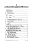
The remaining message types can be set to 0 second. See the Z-12 manual for setting the remaining values; for quick-start, leave at the default values. A typical RTCM-RTK base setup will be
configured as follows:
Figure 3 Typical RTCM-RTK Configuration
6. Press [e] to store the RTCM-RTK mode settings. A message will be displayed to indicate the
output port for the RTCM-RTK message. Press [c] to clear this message. The base station coordinates will now be displayed at the top of the screen.
7
Real-time Z Supplement
CAUTION: DO NOT POWER ON THE DATA RADIO BEFORE
CONNECTING THE UHF ANTENNA. PERMANENT DAMAGE
MAY RESULT.
7. Turn the base data radio on. The red power lamp will be continuously illuminated, and the
green status lamp will blink once each second as a set of RTCM-RTK messages are transmitted on
your licensed radio frequency. Your Real-time Z base station is now operational.
Note: The Z-12 provides the user with two different formats for RTCM-RTK Type 18/19 messages. Format A is the default setting and is recommended for Ashtech to Ashtech operation. For
Ashtech to Trimble operation use Format B. Format B can be engaged through screen 8 by entering the command 731. To swich back to Format A enter the command 730, or perform an internal
memory reset.
Rover Station Setup (RTCM -RTK)
1. Set up the GPS antenna with an unobstructed view of the sky. Connect the GPS antenna to the
Real-time Z receiver. Connect the UHF antenna to the data radio. Connect the data radio serial
port to Port 2 of the receiver. Connect the power cables to the Real-time Z receiver and data radio.
2. Turn on the receiver. If the receiver settings have been changed from the factory default settings, you may restore the default settings by pressing down the [_] key while switching the
receiver on. Hold down the [_] key until the internal test message appears. Release [_] and press
the yes key [8]. After internal test completes, press any key to continue power-on sequence.
3. The Skysearch screen (Screen 0) will be displayed after turning the unit on. Wait until four or
more channels display LK, which indicates that the GPS satellite signal has been locked on. This
should take less than a minute. View the position screen by pressing [2]. Because the almanac
information is erased during the internal test, it may take up to four minutes before the first position is displayed. If at any time the display's backlighting turns off, press any key to turn it back
on.
4.Press [4] to view the mode control screen. Press [e] and move the cursor to DIFFERNTL using
the arrow keys. Press [e] again to view the DIFFERENTIAL MODE SELECTION subscreen.
Press [+] twice to change the mode from DISABLED to REMOTE. Press [e] to store the setting.
Press [e] again and move the cursor to PHASE DIF. Press [e] again, and press [+] twice to select
rover. Press [e] to store the setting. The rover is now programmed for RTCM-RTK CPD mode.
5. Turn the data radio on. The red power lamp will be continuously illuminated, and the
green status lamp will blink each second as a set of DBEN messages are received on your licensed
radio frequency. Your Real-time Z rover station is now operational.
6. Press [2] to view the position screen. Press [_] to view the CPD rover position page.
This page now displays the rover's position with centimeter accuracy. Your Real-time Z system is
now operational.
Note: The RTCM auto-differential mode will be automatically activated once your Z-12 has been
configured as a roving unit. This enables the Z-12 to continue to compute a position (autonomous) in the event that a disruption occurs to the differential data link.
EQUIPMENT SETUP
This chapter describes in detail how to set up both the base and rover stations for Real-time Z sys-
8
Real-time Z Supplement
tem operation. Refer to Figures 1 and 2 in the Real-time Z System Overview chapter which show
the physical connections between all the necessary equipment for the base and rover. Note that
radios have already been pre-configured to operate as required by the Real-time Z system. Specific directions for configuring and operating the base and rover radios are given in the chapter
System Performance Optimization.
Base Station
Below is a step-by-step procedure for setting up the base station:
1.
Select the site for the base station GPS antenna. Where feasible, the base station GPS
antenna should be mounted for an unobstructed view of the sky. For permanent
installations, the antenna should be mounted on a mast 2-3 meters high to reduce
multipath. Do not mount the antenna over water or metal surfaces. Nearby foliage, such as trees, can also introduce multipath.
2.
Install the base GPS antenna over a monument (that is, a known location). This is typically
done by using a tripod, tribrach, and a tribrach adapter. Measure the antenna
height above the monument.
3.
Install the base radio antenna. Note that the radio antenna can be installed at the GPS
antenna location by placing the included mounting bracket between the GPS
antenna and the tribrach adapter, or it can be installed separately. You may want
to install the radio antenna on a high mast for long distance transmission.
4.
Connect the GPS antenna to the Z-12 receiver with the 10-meter GPS antenna cable.
5.
Connect the radio antenna to the base radio transmitter with the radio antenna cable. Refer
to the radio manual for connections for high or low output.
6.
Connect the appropriate data cable between base radio and the Z-12 receiver.
Note: For consistency, it is recommended that you use Port 2 on the
back of the Z-12 receiver. This is because Port 2 will also be used on
the rover's Z-12 receiver for connection to its radio.
7.
If you are using an Ashtech-supplied 12-volt battery, connect this to the Z-12 receiver
using the power cable. If you are using your own power supply, make sure it can
deliver at least 12 watts of power (a minimum of 10 volts at 1.5 amps). Turn the
Z-12 receiver power switch on.
Warning: Never power on a radio without first connecting an
antenna to it!
8.
With the above warning in mind, connect power to the radio transmitter using the radio
power cable and turn the power on.
Rover Station
Set up the rover station as specified in the following procedure.
1.
Place the rover GPS and radio antennas on their mounts.
2.
Connect the GPS antenna to the Z-12 receiver with the 10-meter GPS antenna cable or the
3-meter GPS antenna cable.
9
Real-time Z Supplement
3.
Connect the rover radio antenna to the radio using the cable from the vehicle magnetic
mount. (Note that this cable has a TNC-type connector on one end.)
4.
Connect the rover's radio to Port 2 of the Z-12 receiver using the provided data cable.
5.
If you are using an Ashtech-supplied 12-volt battery, connect this to the Z-12 receiver
using the power cable. If you are using your own power supply, make sure it can
deliver at least 12 watts of power (a minimum of 10 volts at 1.5 amps). Turn the
Z-12 receiver power switch on (ON/OFF switch located on rear panel of
receiver).
Warning: Never power on a radio without first connecting an
antenna to it!
6.
With the above warning in mind, connect power to the rover's radio using the radio/Z-12
power cable and turn the power on.
RECEIVER CONFIGURATION
This chapter details how to set up the Z-12 receivers for the base and rover stations for normal
Real-time Z system operation. Receiver screens are shown when necessary. Note that not all the
setup parameters on these screens are explained here - the remaining parameters are explained in
the chapter System Performance Optimization.
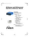
Check the Options
The receiver type and the firmware version number on the bottom right-hand corner of Screen 0
of the receiver indicates if the receiver is capable of performing real-time carrier phase differential
positioning; that is, if the receiver can be configured properly for the Real-time Z system. The
receiver type "Real-time Z" and a version number where the second character is a “J” (such as
1J00) indicate that the receiver has this capability.
Figure 4 Screen 0
To find out more details about your receiver options:
10
Real-time Z Supplement
1.Go to Screen 4 by pressing [4].
Figure 5 Screen 4
2.
Press [e] to enter edit mode. Using the arrow keys, select the SUBCMDS menu item. Press
[e] again to enter the SUBCMDS screen.
Figure 6 Screen 4 Subcommands Subscreen
3.
Enter “888” in the CODE OF COMMAND field and press [e]. The receiver configuration
11
Real-time Z Supplement
will be displayed:
Figure 7 Screen 4, Configuration Identification Display
For a receiver capable of real-time centimeter-level positioning, the last character of the options
field should be “J”, where “J” indicates the Real-time Z mode option. Press [e] to return to Screen
4. If you want the display backlighting to remain on, go to the SUBCMDS subscreen as described
in step 2. Enter "101" in the subcommands field, and press [e], but remember that backlighting
draws an additional 2 watts from the power source. Press [e] or any other key again to return to
Screen 4.
Reset the Z-12 Receivers
Prior to setting up the Z-12 receivers for Real-time Z mode operation for the first time, it is wise
to reset the receivers to their factory defaults. To do this, perform the following steps:
1.
Turn off the receiver if it is on.
2.
Press and continue pressing [C] while turning on the receiver.
3.
After a moment the receiver displays a message requesting you to press [YES] within 10
seconds to reset the internal RAM (the setup parameters). Press [YES] or [8] to
get the internal RAM test display. The following message is displayed after completion of the internal reset:
Testing NAV board internal RAM.
NAV board internal RAM test passed.
Push any key to continue.
4.
Pressing any key except [E] returns you to Screen 0.
Note: If your receiver does not have data storage capability, skip the next
two steps.
5.
If you want to also reset the data storage memory, press [E] at the PUSH ANY KEY
prompt in step 4, and the receiver will display a message asking you to press
12
Real-time Z Supplement
[YES] within 10 seconds to reset the external RAM (the data storage memory).
WARNING: Resetting the data storage memory will erase all previously
stored data files.
6.
Press [YES]. This display is shown below:
Testing external RAM board...
RAM option board test passed.
Push any key to continue.
7.
When the prompt for PUSH ANY KEY TO CONTINUE is displayed again (which could
be a minute or two if you have a large amount of data storage memory), press
any key to complete the reset procedure.
Resetting the receiver returns all parameters to their factory default values and erases any stored
almanac information. The first time after this reset, the receiver will take slightly longer to acquire
satellites.
Set Up the Base Station
Assuming that the base station has not been previously set up and all its parameters are at their
factory defaults, perform the following steps:
Enter Site ID
A meaningful site identification name aids in data management and post-processing. A site ID
must be entered at the base for surveying.
1.
Go to Screen 9 by pressing [9].
Figure 8 Screen 9 - Site and Session Control
2.
Press [e] to activate the cursor. Enter the 4-character site ID of the base in the SITE field.
Press [e] again.
13
Real-time Z Supplement
Set Up the Radio
NOTE: The following setup is applicable only to the Ashtech data radio.
3.
Go to Screen 4 by pressing [4]. Press [e], and move the cursor to select the MODEM subscreen. Press [e] to display the Modem Setup menu.
Figure 9 Screen 4, Modem Setup Menu
4.
Make sure the PORT field is set to B. (Use [+] or [-] to change it.) This should be the port
you connected the radio to. Note that Port B is labeled PORT 2 on the back of the
receiver.
5.
Move the cursor to the TYPE field. If necessary, press [+] or [-] to change the field to
ASHTECH DATA RADIO.
6.
Press [1] and the display will show PRESS ANY KEY, THEN WITHIN 10 SEC. TURN
THE RADIO MODEM OFF AND ON.
7.
Press any key, for example the [e] key. Within 10 seconds, turn the radio off and then on.
If the radio is off, just turn it on.
8.
The receiver screen will flash a message TEST PASSED and will display the radio parameters.
If the receiver displays the message CANNOT CONNECT TO RADIO
MODEM, check your cable connections and radio power source. Also, check
the PORT field on the Modem Setup subscreen and the baud rate in the Port A or
B Setup subscreen. If the message BAD CHECKSUM WAS RECEIVED is displayed, turn off the data radio and repeat steps 4 through 6. Turn the radio on
only when the message SETTING INTERFACE TO RADIO MODEM is dis-
14
Real-time Z Supplement
played.
Figure 10 Screen 4, Modem Setup Subscreen
You can change three items on this screen: the channel, the data link speed, and
the sensitivity. When the cursor is at the V field, you can select the CHANNEL
between 00 and 15 by pressing the [+] or [-] key. When the cursor is in the 2character field to the right of V, you can type in the channel ID (0-15). Also, you
should use the [+] or [-] keys to select the SENSITIVITY and LINK SPEED.
Make sure the channel is set to transmit on the frequency that you have a license
for and that your data link speed is 9600 baud. Also, verify that the sensitivity is
9.
Press [e] to program the data radio.
Caution: Do not unplug the serial cable or power down the data radio during programming. The radio memory will be corrupted and will require
reprogramming the default parameters. See Appendix A for instructions
on reprogramming the default parameters.
10.
Press [e] to exit to Screen 4.
15
Real-time Z Supplement
Set Up the GPS Receiver in CPD Base Mode
11.
From the Screen 4 list of subscreens, move the cursor to PHASE DIF and press [e]. The
following map shows the options available under PHASE DIF.
Figure 11 Screen 4, Carrier Phase Mode Selection
12.
Use [+] or [-] to change the first field to BASE. If the port setting is not correct, move the
cursor to the USE PORT field and change it.
Enter the Base Station Coordinates
13.
Move the cursor to the THIS COORDINATES field and press [1] to display the This Station Coordinates subscreen.
16
Real-time Z Supplement
Figure 12 Screen 4, This Station Coordinates Subscreen
14.
Enter the WGS-84 position of the base station, the antenna height, and any offsets. (If you
prefer to enter the base station coordinates in degrees:minutes format, enter them
on the first line of Screen 4.) Press [e] twice to save the changes and return to
Screen 4.
This position will now be displayed both on Screen 4 and on the THIS COORDINATES display of the PHASE DIF subscreen.
At this time you should see the STATUS light on the base radio flashing green
every second as it broadcasts the DBEN message.
If the position you enter is incorrect, or the receiver's computed position differs
by a large amount, the position display on Screen 4 will flash to alert you of this
situation. A beep will accompany this flashing for one minute.
Warning: The following setup is valid only for distances less than 1
Km. More accurate base station coordinates are required for any
other situation.
If you do not know your coordinates, you can log the currently computed position. First, make
sure your GPS receiver is computing position by viewing Screen 2 and seeing that the position is
continuously being updated with PDOP less than 5. From Screen 4 move the cursor to the PHASE
DIF field. Press [e]. Move the cursor to the SOLUTION PARAMS field. Press [1]. Move the cursor to the ENTER RAW BASE POS field. Press [e]. The message RAW POSITION IS
ENTERED AS BASE POSITION will be displayed. Press [c] to clear the message. Press [c] once
more to return to the Carrier Phase Mode Selection subscreen. Press [e] to exit to Screen 4.
17
Real-time Z Supplement
Save the Setup
15.
From Screen 4, move the cursor to SUBCMDS and press [e].
Figure 13 Screen 4, Subcommands Menu
16.
Enter “555” and press [e]. This will save the parameters for the base station so that the
setup will not need to be performed again after the receiver has been turned off,
or a loss of power has occurred.
17.
Press [e] to return to Screen 4. The setup is complete.
Set Up the Rover Station
Assuming the rover receiver has not previously been set up and all parameters are at the factory
defaults, perform the following steps:
Set Up the Radio
NOTE: The following setup is applicable only to the Ashtech data radio.
1.
Go to Screen 4. Press [e], and move the cursor to select the MODEM subscreen. Press [e]
18
Real-time Z Supplement
to display the Modem Setup Menu.
Figure 14 Screen 4, Modem Setup Menu
2.
Make sure the PORT field is set to B; use [+] or [-] to change it. This should be the port
you connected the radio to. Note that Port B is labeled PORT 2 on the back of the
receiver.
3.
Move the cursor to the TYPE field. If necessary, use [+] or [-] to change the field to ASHTECH DATA RADIO.
4.
Press [1] and the display will show PRESS ANY KEY, THEN WITHIN 10 SEC. TURN
THE RADIO MODEM OFF.
5.
Press any key, for example the [e] key. Within 10 seconds, turn the radio off and then on.
If the radio is off, just turn it on.
6.
The receiver screen will flash a message TEST PASSED and will display the radio parameters.
If the receiver displays the message CANNOT CONNECT TO RADIO
MODEM, check your cable connections and radio power source. Also, check
the PORT field on the Modem Setup subscreen and the baud rate in the Port A or
B Setup subscreen. If the message BAD CHECKSUM WAS RECEIVED is displayed, turn off the data radio and repeat steps 4 through 6. Turn the radio on
only when the message SETTING INTERFACE TO RADIO MODEM is dis-
19
Real-time Z Supplement
played.
Figure 15 Screen 4, Modem Setup Subscreen
You can change three items on this screen: the channel, the data link speed, and
the sensitivity. When the cursor is at the V field, you can select the CHANNEL
between 00 and 15 by pressing the [+] or [-] key. When the cursor is in the 2character field to the right of V, you can type in the channel ID (0-15). Also, you
should use the [+] or [-] keys to select the SENSITIVITY and LINK SPEED.
Make sure you are using the correct frequency that you have a license for and that your
data link speed is 9600 baud. Also, verify that the sensitivity is set to MEDIUM
or HIGH.
7.
Press [e] to program the data radio.
Caution: Do not unplug the serial cable or power down the data radio during programming. The radio memory will be corrupted and will require
reprogramming the default parameters. See Appendix A for instructions
on reprogramming the default parameters.
8.
Press [e] to exit to Screen 4.
20
Real-time Z Supplement
Set the GPS Receiver in CPD Rover Mode
9.
Move the cursor to the PHASE DIF field. Press [e] to display the Carrier Phase Mode
Selection subscreen.
Figure 16 Screen 4, Carrier Phase Mode Selection Subcreen
10.
Use [+] or [-] to change the first field to ROVER. If the port setting is not correct, move
the cursor to the PORT field and change it.
11.
Press [e] to leave the PHASE DIF subscreen.
High Speed Solution Computation
The Quick Measurement option (Q) provides the Real-Time Z user with the ultimate high speed
accuracy. A Z-12 configured with the Q option can output new, independent solutions at 1Hz,
2Hz, and 5Hz with extremely low solution latency - typically 100 to 125 milliseconds. This feature makes the Real-Time Z ideal for navigation and machine control as well as other dynamic
applications which demand high speed performance.
To verify the presence of the Q option in your receiver, go to screen 8 and enter the command 888.
The response message will display a field entitled OPT which lists the configured options. The
following section provides the necessary information to generate 2 and 5Hz solution computations for those users who have the Q option installed.
21
Real-time Z Supplement
Go to screen 4, highlight the RCVR CTRL field, and press Enter.
Figure 17 Screen 4, Receiver Control
The last field in the RECEIVER CONTROL MENU is entitled CYCLE TIME and controls the
solution computation rate. The default with the Q option installed in 0.50 seconds (2Hz). To
change to 5Hz enter 0.2. The receiver will power cycle after this command is sent, so it is a good
idea to save all current settings before changing the cycle time. The following table summarizes
the relationship of the CYCLE TIME settings to the raw data recording interval (INTVL) and to
the real-time output rate (send interval).
Table 1: Cycle Time vs Raw Data Recording Interval
Cycle Time with Q Option
Raw Data Interval
Real-Time Output
Solution Update Rate
1
20 seconds
5.0 seconds
1 Hz
0.50
0.50 second
0.5 second
2 Hz
0.20
0.20 second
0.2 seconds
5 Hz
Note: Raw data collected for post-processing purposes must be recorded at a rate of 1Hz or
slower. Data collected at a 2 or 5Hz rate cannot be post-processed.
Save the Setup Parameters
22
Real-time Z Supplement
12.
In Screen 4, move the cursor to SUBCMDS, and press [e].
Figure 18 Screen 4, Subcommands Subscreen
13.
Enter “555” and press [e]. This will save the user parameters for the rover station setup so
that the setup will not need to be performed again after the receiver has been
turned off, or a loss of power has occurred.
14.
Press [e] to return to Screen 4. The setup is complete.
At this point, the receiver will operate in the CPD Rover mode. If you would like
to optimize the CPD setup parameters for your application, see the chapter System Performance Optimization. If this is the first time you are setting up the CPD
rover receiver, it is recommended that you stop the rover receiver setup here.
ROVER SOLUTION MONITOR
When the rover station's GPS receiver is set to Carrier Phase Differential mode (see Receiver
Configuration chapter), you can view the current position solution results and status on the appropriate pages of Screens 2 and 20. These screens are described below.
Screen 2
Page 1 of Screen 2 shows autonomous position information based on the raw, uncorrected
23
Real-time Z Supplement
pseudo-ranges.
Figure 19 Screen 2, Page 1
For page 2 of Screen 2, the ENU velocity and waypoint navigation information uses the CPD
position solutions if the receiver is in CPD ROVER mode. Otherwise, the raw uncorrected
pseudo-ranges are used.
Position information in this page and also in page 3 can be displayed in various datums or UTM
coordinates by selecting the appropriate parameters in Screen 4.
Figure 20 Screen 2, Page 2
Screen 2 now has an additional page, page 3, accessed by [C] or [D] when the receiver is set to
24
Real-time Z Supplement
ROVER mode for CPD.
Figure 21 Screen 2, Page 3
Notice that the layout of page 3 is identical to page 1, except that there is more precision in the
LAT, LON, ALT parameters and the SGM parameter is shown instead of FOM. The SGM parameter, or sigma, is the root mean square (RMS) three-dimensional position error for the current
epoch.
25
Real-time Z Supplement
Screen 20
Screen 20 of the rover receiver is accessed as follows: Press [0] to go to Screen 0, then press [F]
to go to Screen 20. There are five pages in Screen 20 which display the CPD solution in different
formats.
Figure 22 Screen 20, Page 1
Figure 23 Screen 20, Page 2
26
Real-time Z Supplement
Figure 24 Screen 20, Page 3
Screen
Figure 25 Screen 20, Page 4
27
Real-time Z Supplement
Figure 26 Screen 20, Page 5
The left side of each page displays the position, velocity and a solution quality value. The right
side of each page displays the solution status and other information.
Position Information
The left side of the five pages displays the rover's position coordinates in WGS-84, local ENU
(East, North, Up) frame relative to the base station's position, Earth-Centered, Earth-Fixed
(ECEF) XYZ, the vector solution (between the base and rover stations) in _X, _Y, _Z, and vector
solution in Distance, Azimuth, and Elevation. Position information on page 1 of Screen 20 can be
displayed in various datums or in UTM coordinates.
An important indicator of position solution quality is the SIGMA parameter. The SIGMA value is
an estimation of the 3-D position error based upon an RMS computation.
PNAV Solution Status
PNAV status parameters on the right-side of Screen 20 can be used for information about the current state of the PNAV processing engine.
The top line shows a time indication. This time is for the currently displayed position solution,
which is delayed from the time shown in Screen 0. The amount of delay, or latency, depends on
the data link and whether Fast CPD is on or off. See the section System Performance Optimization
for more information on Fast CPD.
- "PN: INIT" and "RUN".
Parameters "INIT" and "RUN" display how many initializations and runs of PNAV have
occurred.
- "PN FLAGS: OK UP NO X".
The four parameters (“OK UP NO X”) show the internal state of PNAV:
28
Real-time Z Supplement
1 - States of PNAV. It can have the following states:
- "OK" - working normally
- "FI" - full initialization
- "BR" - bad residual
- "ME" - missed epoch
2 - Solution type. It can have the following states:
- "UP" - updated
- "PR" - projected
3 - Cycle slip. It can have the following states:
- "NO" - no cycle slip
- "CS" - cycle slip
4 - Ambiguity fixing status flag:
- "X" - integer ambiguities are fixed
- "F" - integer ambiguities are float (not fixed)
- "SVs ROVR" and "SVs BASE".
These parameters allow you to see how many satellites the receiver is tracking (the PL1 pseudorange, PL1 carrier phase, and PL2 carrier phase measurements) and using in the DBEN messages
of the rover and base receiver. If there is no DBEN message at all, a '--' will appear here.
The number of common satellites between the base and rover stations is shown at the end of "SVs
ROVR" row. Additionally, at the end of "SVs BASE" row, there is a flag that can have two states:
'+' and '-'. When the DBEN message is received by the serial port of the receiver, this flag is set to
'+'; when the DBEN message is not being received, this flag is set to '-'.
- "DLf" and "Tf".
"DLf" shows the delay from GPS time to the starting time of Fast CPD position computation, in
milliseconds. "Tf" shows the computation time of the Fast CPD solution, in milliseconds.
The quantity ("DLf" + "Tf") shows the total delay of the Fast CPD solution. This number should
be the difference between the times displayed in Screen 20 and Screen 0. This is also the delay of
the real-time output messages. When Fast CPD is turned off, this line displays "DLf 00000 fCPD
OFF".
-"DLc" and "Tc".
"DLc" shows the delay from GPS time to the starting time of the matched time-tag position computation, in milliseconds. "Tc" shows the computation time of the matched time-tag (PNAV processing) solution, in milliseconds.
The quantity ("DLc" + "Tc") shows the total delay of the matched time-tag solution. This number
should be the difference between the times displayed in Screen 20 and Screen 0 when Fast CPD is
off. This is also the delay of the real-time output messages when Fast CPD is off.
29
Real-time Z Supplement
To stop the update of information on any of the five pages of Screen 20, a "freeze mode" is available. If [c] is pressed when Screen 20 is active, information on the screen is not updated. This is
useful for those who need to record information directly from the Screen 20 display. To switch
this mode off, press [c] again.
30
Real-time Z Supplement
Screen 5
Page 3 of screen 5 shows information on CPD phase residuals and status. This screen is relevant
for a CPD rover or for a reverse vector base (RAP).
Figure 27 Screen 5, Page 3 - Phase Residuals
CPD Phase Residuals
The left and center portions of the screen display information regarding the individual phase
residuals associated with each space vehicle (SV). This information is divided into the following
five
PRN
The PRN (pseudo-random number) field shows the PRN numbers of all the satellites being used
in the rover (or RVP base) solution computation. The PRN field is a listing of all SV's common to
both base and rover which are being used in the solution computation.
ELV
The ELV (elevation) field provides the current elevations of all common SV's.
L1F
The L1F field contains phase residual measurements for each SV in terms of the Fast CPD cycle.
Accordingly, the L1F field will not contain any information if the Fast CPD cycle is not engaged.
Reverse video indicates a negative phase residual for that SV. All measurements are reported in
millimeters.
L1P/L2P
The L1P and L2P fields contain phase residual measurements for each SV in terms of the regular
CPD cycle. Once carrier phase operation is initiated (either DBN or RTCM - RTK), these fields
will begin displaying phase residual information for both bands. Reverse video indicates a negative phase residual for that SV. All measurements are reported in millimeters.
31
Real-time Z Supplement
The right side of the screen displays information associated with the ambiguity fixing status and
RMS error values. This information is divided into the following three fields:
AMBFIX STS
Information relating to the ambiguity search is presented in this field. The far left side of this field
will contain either an X or an F. An X signifies a fixed CPD solution where the ambiguities have
been resolved. An F signifies a float CPD solution where the ambiguities have not been resolved.
The far left side of this field will contain either 1.00 or a number less than 1.00. A display of 1.00
indicates a fixed CPD solution, whereas a number less than 1.00 indicates the ambiguities have
not been resolved.
RESD
The RESD (residual) field contains the root mean square (RMS) phase residual errors for the fast
CPD cycle and for the regular CPD cycle. The RESD field is divided into the sub-fields f and c.
The f sub-field contains the RMS phase residual errror in millimeters for the L1F field. The c
sub-filed contains the RMS phase residual error in millimeters for the combined L1P and L2P
fields.
SIGMA
The SIGMA field contains the 3-D RMS position estimation error for the fast CPD cycle and for
the regular CPD cycle. The field opposite the f displays the 3-D RMS position estimation error in
millimeters for the fast CPD cycle. The field opposite the c field displays the 3-D RMS position
estimation error in millimeters for the regular CPD cycle.
DATA LINK MONITOR
Screen 5 is used to monitor the status of the data link being used for CPD. Pages 1 and 2 of Screen
5 show RTCM and satellite range error information. Press [_] twice to view page 3, which displays the CPD data link status for either the base or rover stations. This page is activated only
when receiver is in CPD mode
Base Screen 5
32
Real-time Z Supplement
When the receiver is in CPD BASE mode, page 3 of Screen 5 looks like:
Figure 28 Screen 5, Page 3 - CPD Data Link Status for Base
See the section below for a description of the display parameters.
Rover Screen 5
When the receiver is in CPD ROVER mode, page 3 of Screen 5 looks like:
MODE displays the current receiver CPD mode - BASE or ROVER.
INTVL sample rate for QA computation
BASE STAT displays the base station status as follows: “ABCDE”, where
A
displays “1” if the receiver has not tracked the L2 observables.
B
displays “1” if the entered position and computed position differ by more than 500
meters in any direction.
C
displays “1” if the base station has not computed position using the raw pseudoranges.
D
displays “1” if base station antenna parameters are all zeros.
E
displays “1” if the base station coordinates are not entered.
PRN lists the satellites' PRN ID in the transmitting DBEN message or received DBEN message.
If the first digit is shown in reverse video, P-code L1 is not locked. If the second digit is shown in
reverse video, P-code L2 is not locked.
DBEN TIME displays current DBEN time (base only).
SETD ID displays the set DBEN message header.
RCVD ID displays the DBEN message header received. The SETD ID and RCVD ID should
always be the same.
33
Real-time Z Supplement
CORD USED displays which base station coordinates are used in the PNAV data processing.
RCVD CORD displays the age of the received base station coordinates in seconds.
RX
DT average interval of incoming CPD differential messages
QA displays the percentage of DBEN messages received over the last three minutes. A typical
radio link has a QA value between 90 and 100 percent.
AGE displays the DBEN message age in milliseconds. This is always zero at the base.
34
Real-time Z Supplement
CPD SOLUTION STORAGE AND UTILIZATION
To maintain compatibility with existing Z-12 interface software, the existing real-time solution
output format and data storage have not been changed in Real-time Z. However, when operating
the receiver in CPD rover mode or RVP base mode, the messages and stored data will contain the
precise CPD solutions. In addition, some new real-time output messages have been added to supply additional CPD solution information.
Solution Storage
If your receiver has the external memory option, you can store the raw measurements and the
solution information into the receiver's memory. These data can then be downloaded to a PC into
B, E, and S file format via Ashtech's GPPS-HOSE or PRISM-TRANSFER programs at a later
time.
The receiver's data storage control is the same as a standard Z-12. Simply verify the following
receiver setup parameters:
In Screen 4, the INTVL, MIN SV, and ELV MASK control the satellite measurement data storage
and output. The ELV MASK setting on the base affects which satellite information is contained in
the DBEN message. Also, set RNGR to "0" to collect all raw measurements or "2" to only store
the position information.
In the POSITION subscreen, UNHEALTHY should be set to N so that unhealthy satellite signals
are not used to compute the position. The base will transmit DBEN message information for
unhealthy satellites, but the rover will use them only if this flag is set to Y in the rover.
In Screen 9, set the SITE name, and set RECORD to Y.
Since CPD is a differential operation, a solution may not be available if the differential data link is
lost. However, the receiver will always store the raw measurements whether the CPD solution is
available or not. When the CPD solution is not available, the position computed by the raw
pseudo-ranges will be stored instead.
Vector Solution Storage
This capability allows you to log vector solutions containing the same information as post-processed vector output files, allowing the measurements to be imported into an adjustment program.
Your Real-time Z measurements may then be included as part of a least-squares network adjustment.
To use this option, a valid site name must be entered (in Screen 9), and the rover's GPS antenna
must remain stationary until the site name has been changed to "????". If the GPS antenna is moving with a site name entered, the vector solution will not be valid. If no site name is entered, the
vector solution will not be created. Note that a site name must be entered at the base station as
well.
Other Ashtech Real-time Z products with software running on a handheld datalogger automate
this process, but it may be performed in the basic Real-time Z system using the following procedure.
Check the solution in Screen 20 to ensure that the current accuracy meets your requirements.
Place the antenna over the point to be measured, then issue the following serial commands to the
35
Real-time Z Supplement
receiver using Ashtech's REMOTE program or a similar serial port I/O program:
$PASHS,CPD,DYN,0
$PASHS,CPD,FST,OFF
$PASHS,SIT,xxxx (where xxxx is the site name you wish to use)
These three commands set rover motion dynamics to static, turn Fast CPD off, and set a site name.
To improve the vector solution, you may wait for 5-10 epochs of data before issuing the next set
of commands:
$PASHS,CPD,DYN,2
$PASHS,CPD,FST,ON
$PASHS,SIT,????
These three commands reset the unit for dynamic operation. The receiver will beep twice, indicating that the vector solution has been created.
Now enter the next command to log the solution to the OBEN file:
$PASHQ,OBN
After this, you can move the GPS antenna to the next site.
Real-time Solution Output
The CPD rover position, velocity and other solution information can be output via the receiver's
serial port, in PBEN message format or NMEA message format. The output control of these messages is the same as the standard Z-12 operation. The PBEN message can be logged via Ashtech's
DATALOGR program. The PBEN message output rate is controlled via the Screen 4 INTVL
parameter. The 0.5 second output rate is not available for Real-time Z, since the CPD solution is
computed once per second.
If you want the raw position to be placed in the B-file data and output to the serial port, change the
PHASE DIF solution parameter to OUTPUT RAW POS.
A new CBEN message has been added to provide more complete information on position, velocity, solution status, position RMS and covariance, number of satellites, and PDOP. The CBEN
message can be output in ASCII or binary format. The binary format is bitwise packed and is not
IEEE format compatible.
The output control for the CBEN message is the same as that for PBEN. If for any reason the CPD
solution cannot be computed for an epoch, there will be no CPD solution output for that epoch in
any real-time, VTS, or NMEA message.
Other new messages have also been implemented. These message are only available for query,
they cannot be set to output periodically like PBEN or CBEN messages. These new messages are
UBN and OBN. The UBN message gives CPD position, velocity, and statistical information in
binary format. The OBN message gives CPD vector and site information in binary format.
Refer to the Real-time Z System Integrator's Reference Manual, Ashtech document 630001, for
detailed command format and message content.
36
Real-time Z Supplement
TROUBLESHOOTING
The following problems are sometimes encountered by users new to Real-time Z. If your system
isn’t working properly, please refer to this list, starting at the top. If you need further assistance,
please call an Ashtech customer service representative.
Rover doesn’t show Screen 20
First, verify that the receiver is capable of Real-time Z operation. On Screen 0, verify that "Realtime Z" is shown in the middle of the seventh line, and that the firmware version number in the
lower right corner is similar to 1J00-1C63, where the “J” indicates Real-time Z. Next, enter subcommand [888] on Screen 8 to check the options. The last letter of the “OPT” line must be a “J”.
Finally, verify that the receiver is in rover mode by selecting PHASE DIF on Screen 4 and using
[+] to select ROVER mode at the upper left of the Carrier Phase Mode Selection screen. Press [e].
View Screen 20 by pressing [0] then [F].
Base doesn’t show Screen 5 CPD Data Link Status page
Verify that the receiver is in base mode by selecting PHASE DIF on Screen 4 and using [+] to
select BASE mode at the upper left of the Carrier Phase Mode Selection subscreen. Press [e]. Go
to Screen 5 by pressing [5], then select the CPD data link status page by pressing [C] twice.
Base CPD Data Link Status page doesn’t show PRN numbers
Verify that the antenna connection on the back of the receiver is connected to the GPS antenna.
The GPS antenna must be mounted outdoors, with a clear view of the sky. Nearby buildings and
vegetation can block the GPS signals or introduce multipath by reflecting the GPS signals.
Base beeps and Screen 4 position flashes
The entered coordinates differ from the computed coordinates by more than 500 meters. Verify
and re-enter the coordinates on Screen 4, or use the SOLUTION PARAMS subscreen to enter the
raw position as the base coordinates.
Base data radio status light isn’t blinking every second
Verify that the port setting on the Screen 4 PHASE DIF subscreen matches the serial port that the
data radio is connected to. Remember that Port A corresponds to Port 1 on the back of the
receiver, and Port B corresponds to Port 2. Set the baud rate to 9600 on the Screen 4 PORT A or B
subscreen. Verify that the NMEA, REAL TIME, and VTS outputs are off. Verify that RTCM
mode is disabled. Check that the DBEN message interval is set to 1 second on the DATA SELECTION subscreen of Carrier Phase Mode selection. Verify that on the MODEM subscreen of
Screen 4 the port and modem type are set for the Ashtech radio. Turn off the radio, press [1], and
then any key. Turn on the radio and verify that you get a TEST PASSED message. Press [e] to reprogram the data radio. Run the data radio setup software per Appendix A and per the data radio
manual to verify that the radios contain the default settings.
Rover data radio status light isn’t blinking every second
Verify that the PHASE DIF and MODEM serial port settings are correct. Check that the PORT
baud rate is 9600. Verify that the NMEA, REAL TIME, and VTS outputs are off. Verify that
RTCM mode is disabled. Check the radio setup on the base and rover to verify that the same channel and frequency are being used. Verify that a line of sight path exists between the base and rover
data radio antennas. Place the base station data radio in high power mode. Run the data radio
37
Real-time Z Supplement
setup software per Appendix A and per the data radio manual to verify that the radios contain the
default settings.
Base station status on Screen 5 is not “00000”
At the base station, enter antenna height and base coordinates. Verify that the entered base coordinates are correct. Verify that Screen 0 shows LK for STAT, PL1, and PL2 for at least four satellites.
Position is not updating on rover Screen 20
Verify on Screen 5, page 3, that at least 4 PRN numbers are shown in normal video. A reverse
video PRN number indicates that not all signals are being tracked for that satellite. Reposition the
GPS antenna away from obstructions. On Screen 20, verify that the SVs ROVR and SVs BASE
rows show at least 4 SVs are being tracked for P1 and P2. Verify that the number of satellites
common between the base and rover is 4 or more. This number is shown in the last column of the
SVs ROVR row on Screen 20.
Screen 20 doesn’t update every second or beeps and flashes OLD
Monitor the data link quality on Screen 5. The QA number should be 90% or higher. Verify that
FAST CPD ON is selected on the Solution Parameters subscreen of PHASE DIF. Verify that a line
of sight path exists between the base and rover data radio antennas. Place the base station data
radio in high power mode. Refer to the System Performance Optimization Chapter.
Screen 20 only shows float solution
On Screen 20, verify that the SVs ROVR and SVs BASE rows show at least 5 SVs are being
tracked for P1 and P2. Verify that the number of satellites common between the base and rover is
5 or more. Even if 5 or more satellites are tracked, you still may not get a fixed solution at locations with severe multipath.
Real-time Z solutions are not being stored in the rover
Verify that on Screen 8, "RAM BOARD NOT INSTALLED" is not shown. Verify that OUTPUT
CPD POS is selected in the Solution Parameters Selection subscreen of Carrier Phase Mode
Selection. Verify that Screen 9 RECORD is set to Y. Verify on Screen 8 that several EQHR are
available. Set the INTVL on Screen 4 to 1 second for a faster recording rate.
38
Real-time Z Supplement
SYSTEM PERFORMANCE OPTIMIZATION
CPD Solution Parameters
The Solution Parameters Selection subscreen of the Carrier Phase Mode screen allows you to
match the CPD solution parameters to your specific application. These parameters, unless otherwise indicated, are set at the rover only.
Figure 29 Screen 4, Solution Parameters Selection Subscreen
Dynamics
Select the dynamics for the fastest speed that you expect to be moving. If the dynamics are not set
properly, the CPD solution will be less accurate. Use the STATIC dynamics mode only if the
antenna will remain on a solid setup such as a tripod. If the antenna is on a pole that may have
some slight movement, select Q-STATIC. If you are doing stop-and-go kinematic or rapid static
surveys, the WALKING or AUTOMOBILE dynamic should be selected. SHIP dynamics assume
limited vertical movement. AIRCRAFT dynamics assume higher speeds and accelerations.
Multipath
Set this parameter to the expected GPS signal multipath environment according to the list below:
SEVERE
Forest, urban canyon
HIGH
Water surface, nearby buildings
MEDIUM
Cropland, occasional tree or building
LOW
Flat terrain, no nearby objects
NONE
No multipath
Initialization
If you wish to reset the carrier phase cycle ambiguities that have been found, select FULL INITIALIZE. The message PHASE DIF SOLUTION IS INITIALIZED will be displayed. Note that
39
Real-time Z Supplement
your position accuracy will temporarily degrade and you should wait until the ambiguities are
fixed again before expecting centimeter accuracy.
Fast CPD
Fast CPD off achieves the ultimate in GPS accuracy. With Fast CPD off, sub-centimeter position
solution accuracy can be obtained with fixed integer ambiguities. However, it suffers from solution delay. This delay is caused by measurement and radio link delays. The measurement delay is
about 1 second. Typical radio data link delays are about 1 second also. DLf and Tf are not shown
on Screen 20 when Fast CPD is off.
Turning Fast CPD on reduces the solution delay to less than a quarter second. Because Fast CPD
projects the solution ahead in time, it does not suffer from radio link delays. However, the position
accuracy is only 2-3 centimeters.
Turning FAST CPD on also allows the solution to be available when there is a temporary data
drop-out from the base station.
Base Position
If the transmitted base position were entered incorrectly at the base, you may change this field at
the rover to USE ENTERED BASE POS and then enter the correct base coordinates in the
OTHER COORDINATES subscreen. The CPD data link status on Screen 5 will display the
RCVD CORD age as "999 SEC" when the entered page position is used.
If you are using the transmitted coordinates, which is the recommended method, you can verify
the transmitted position by viewing the OTHER COORDINATES subscreen.
Ambiguity Fix Mode
In the Advanced Solution Parameters subscreen, the ambiguity fix mode can be set from 1 to 5.
The default setting of 4 is recommended for most static and kinematic surveying applications.
Setting the mode to 5 results in the highest reliability that the ambiguities are fixed correctly, but
also results in a longer time to resolve the ambiguities and give the fixed solution. Setting the
mode to 2 or 3 decreases the time to resolve the ambiguities and give the fixed solution, but also
increases the chances that the ambiguities are fixed incorrectly. Setting the mode to 1 results in
the shortest time to resolve the ambiguities; however, mode 1 also has the highest chance (typically 2.4 percent) that the ambiguities are fixed incorrectly.
The illustration on the next page shows test results for over 12,000 ambibuity fix tests done by
Ashtech at various baseline lengths up to 9 km. These test results indicate that at the default setting (mode 4), the typical time to resolve the ambiguities is 60 seconds, with a reliability of 99.9
percent. At the fastest setting (mode 1), the results indicate that the typical time to resolve ambiguities is 5 seconds, with a reliability of 96.6 percent.
If the ambiguities are fixed incorrectly, the satellite geometry must change appreciably before the
ambiguities will again fix correctly. For a static rover, this will happen within approximately 10
minutes, or when a new satellite is acquired.
40
Real-time Z Supplement
Figure 30 Carrier Phase Initialization
Update Rate
If you wish to slow down the rover's solution update rate, you can change the Update Rate from 1
to 5 seconds. This does not affect the Screen 20 update rate, which is always 1 second when fast
CPD is on. When you set the Update Rate to 2 or more seconds, the Sigma displayed on Screen 20
each second will increase between computations.
DBEN Message Interval
The DBEN message interval at the base can be set from 0 (no DBEN messages sent) to 999 seconds. This is useful if your application does not have a continuous data link or only requires periodic DBEN messages.
Setting the rover's update rate to match the DBEN message interval allows the rover to compute
solutions at the DBEN message rate. The FULL P CODE and UNSMOOTHED selections on the
DBEN DATA Format Selection page are for display only and indicate L1 and L2 P-code and
unsmoothed pseudo-ranges are being used.
Base Station Elevation Mask
In the base station, set the ELEV MASK to 5 degrees to output GPS measurements for all tracked
satellites. You can set a higher elevation mask angle for position computation in the POSITION
subscreen of the rover.
41
Real-time Z Supplement
Radio Parameters
Careful consideration must be given to the following situations to get the full performance from
the radio data link:
Line-of-Sight Transmission
The Real-time Z system uses radios operating in the VHF/UHF frequency range. These frequencies are predominantly line-of-sight. The base station antenna should be placed as high as possible
for maximum range. However, this needs to be balanced with reasonably short radio antenna
cables, due to the relatively high transmission line loss on a cable when using VHF/UHF frequencies. Foliage, buildings or desert terrain may shorten the transmission distance while improvement may be found in transmissions over water, snow, or ice. The following is a formula for
computing the approximate line-of-sight distances that can be achieved between the base and
rover stations:
d = sqrt[(3*K*h) / 2]
where d is the line-of-sight distance in miles
h is the base station antenna height in feet
K is the surface reflectance coefficient, which is 1.33 for temperate climates
(polar climates will have larger K values).
Data Transmission Rate
To provide real-time, accurate rover position solutions at a 1-second rate, the Real-time Z system
requires radios which can transmit data at a speed of at least 4800 baud. For best performance,
radios capable of a 9600 baud data link speed are strongly recommended. A high data link speed
is required since the base station has to transmit a large amount of data to the rover station in each
message it sends (both GPS carrier phase and pseudo-range measurements).
Sensitivity
The Z-12 receiver MODEM subscreen is used to change the sensitivity of the radio from low to
medium or high depending on the area and the amount of interference. For the base station, the
recommended sensitivity setting is low while for the rover station, it is medium or high.
If you select a channel and you notice that the radio status light is blinking, there is probably
someone broadcasting on that frequency and you should select different channel if you have
another available.
While both the base and rover radio's have been preset to operate in a typical Real-time Z system,
some applications may require changes to the radio parameters. Appendix A tells how to change
the radio parameters and what the default parameters are. Further information can be found in the
included radio manual.
42
Real-time Z Supplement
ERROR SOURCES OF CARRIER PHASE DIFFERENTIAL GPS
Error sources affecting the performance a real-time CPD GPS system can be separated into two
groups - those that affect the radio data link and those that affect the Z-12 GPS receivers.
Radio Link Dropout
When the rover does not receive the DBEN messages, it will continue to compute its CPD position for about thirty seconds if Fast CPD is on. However, the three-dimensional position error
(sigma) will increase during this period. When the DBEN messages are re-acquired, the sigma
will immediately drop to the value before the radio link drop out. If Fast CPD is off, CPD position
computation will stop within seconds of losing the DBEN messages. For best results in the field,
Fast CPD should be left on, and the base radio antenna should be located as high as possible with
a line of site to the rover.
GPS Signal Multipath
Multipath is by far the most unpredictable error source affecting differential GPS position accuracy. Multipath is also one of the largest error sources, and because it has strong correlation, it
requires a longer time to average out its affect. While most error sources can be canceled out by a
differential GPS system, multipath can not because it is a local effect. That is, multipath affects
the base station and rover station differently. To avoid large multipath effects, do not place the
GPS antenna near any metal objects, vegetation, or water, since the GPS satellite signals reflect
off these objects very easily and corrupt the reception of the direct signals from the satellites.
Also, try to mount the antenna higher to reduce the effect of ground multipath reflections.
Satellite Geometry
The recommended satellite geometry is to have the Z-12 GPS receivers (both base and rover)
track at least 5 common satellites above the elevation mask angle with the PDOP (Position Dilution of Precision) less than 4. Of course, the more satellites the receivers track, the better. The best
performance can be obtained with the receivers tracking 8 satellites with a PDOP of 2 or less.
Maintaining Lock to the Satellites
During the operation of the Real-time Z system, it is recommended that continuous lock to the
GPS satellites be maintained for best performance. Having uninterrupted data from the satellites
provides faster ambiguity resolution and better position accuracy, since more data can be used.
Therefore, make sure to place the GPS antennas (for both the base and remote stations) so that
they have a good view of the whole sky. Do not mount them near any large obstructions. However, since it is understood that tracking satellites continuously is sometimes not possible due to
obstructions such as bridges and trees, the Real-time Z system can still recover from these situations and provide the best accuracy possible.
Selective Availability
Selective Availability (SA) is the intentional degradation of the GPS satellite signal by the US
Department of Defense. Like multipath, SA is strongly correlated; but unlike multipath, it affects
the base and rover stations about the same way. Therefore, most of the SA effects can be removed
by a differential GPS system. Note that small position errors will still be present due to SA for any
real-time differential GPS system. This is because the rover may have to predict the SA effect for
the time gap caused by the radio link delay.
43
Real-time Z Supplement
MESSAGE CONTROL
The Message subscreen allows you to exchange messages between the base and rover stations.
The Message subscreen is accessed via Screen 4.
Figure 31 Screen 4, Messages Transmitting/Receiving Subscreen
The message control parameters are:
RCV MSG
enable or disable message reception
BEEP enable or disable beep on receiving a message.
PORT set port for transmitting a message.
PASSWORD set password to encrypt message. If password is different from "????", the
message will be encrypted. Messages will be received on either
BASE or ROVER stations only if the password is the same on
both stations.
MESSAGE
1524
the line below this string is intended for writing a message. Use [C] to
select the character set, press the corresponding key. Use [E] for
space. If the cursor is in this line and [e] is pressed, all symbols
(not more than 35) before the cursor position will be sent to the
designated port.
is the time the message was transmitted (in GMT hours, minutes format; HHMM).
The field <VIEW RCV MSG> allows you to view the last five received messages. When [e] is
pressed at this field, the last five messages are displayed.
44
Real-time Z Supplement
REVERSE VECTOR PROCESSING
In reverse vector processing (RVP), the rover station broadcasts its raw measurement data via a
data radio. The base station, which is at a known site, receives the rover's raw measurement data
and applies phase corrections to it in order to compute the rover's CPD position. Reverse vector
processing can be used to track autonomous vehicles or control remote vehicles in three dimensions with centimeter accuracy.
Equipment Setup
Equipment setup is similar to that of a normal CPD setup, except that the large, high power data
radio is used at the rover to transmit, and the smaller, low power data radio receiver is used at the
base to receive.
RVP Rover Setup
1. Connecting the data radio to port 2 via a RS-232 data cable, turn on the receiver and the
data radio.
WARNING: Do not turn on the radio power if there is no antenna
connected to the radio amplifier.
2. If you are using the Ashtech data radio, you might want to verify the data radio parameters or change the channel as described in the normal CPD setup.
3. Change to Screen 4 and select PHASE DIF to view the CARRIER PHASE MODE
SELECTION subscreen. Select RVP ROVER mode by pressing [+] four
times.
4. If you are interested in getting a position other than that of the antenna phase center,
perform the following: Select THIS COORDINATES and press [1].
Enter the antenna offset parameters: slant, radius, vertical offset, horizontal distance and azimuth. Press [e] to accept the antenna offset parameters. This will bring you back to the CARRIER PHASE MODE
SELECTION subscreen.
5. Press [e] to accept the CPD mode setting. A message will be displayed to indicate the
output port and baud rate for the DBEN message. Press any key to clear
this message.
6. Change to Screen 5, and use [C] to select the CPD Data Link monitoring page. Verify
that at least five PRNs are shown.
RVP Base Setup
1. Connecting the data radio to Port 2 via a RS-232 data cable, turn on the receiver and the
data radio.
2. Change to Screen 4 and select PHASE DIF to view the CARRIER PHASE MODE
SELECTION subscreen. Press [+] three times to select RVP BASE
mode.
3. If you know the coordinates where the RVP base station is located, perform the following commands:
45
Real-time Z Supplement
Select THIS COORDINATES and press [1]. Enter the WGS-84 latitude,
longitude, and altitude using the degrees:minutes:seconds format. Measure and enter the slant distance and antenna radius. Press [e] to accept
the coordinates and antenna offset parameters. This will bring you back
to CARRIER PHASE MODE SELECTION subscreen.
4. If you do not know the base station coordinates, perform the following commands:
While in the CARRIER PHASE MODE SELECTION subscreen, select
SOLUTION PARAMS and press [1]. Move the cursor to ENTER RAW
BASE POS. Press [e] to use the current position computed by raw
pseudo-ranges for the base coordinates. A confirmation message will be
displayed. Press [c] to clear this message. Press [c] again to exit the solution parameters subscreen. Press [e] to accept the CPD mode setting.
This will bring you back to CARRIER PHASE MODE SELECTION
subscreen.
5. Press [e] to accept the CPD mode setting.
6. Change to Screen 5, and use [C] to select the CPD Data Link monitoring page. Verify
that at least five PRNs are shown, and that the QA number is increasing
toward 100%.
Solution Monitoring
Switch to Screen 20 on the RVP base to view the position and velocity of the RVP rover with centimeter accuracy.
The Fast CPD calculation time, Tf, is replaced by the message RVP BASE. Fast CPD is automatically turned off in RVP mode because the base can not predict the movement of the rover.
Solution Output and Data Storage
The real time PBEN, CBEN, and NMEA messages at the RVP base station will now contain the
position and velocity information for the RVP rover. These messages will be available only if the
RVP CPD solution is available.
By default, the RVP base receiver will not store the RVP rover position into the receiver memory.
In order to store the rover position into the receiver memory, perform the following:
Change to Screen 4 and select PHASE DIF to enter the CARRIER PHASE MODE SELECTION
subscreen. Select SOLUTION PARAMS and press [1]. Move the cursor to OUTPUT CPD POS.
Select the OUTPUT RVP POS by pressing [+] or [-]. Press [e] to accept the change and exit the
solution parameters subscreen. Press [e] to accept the CPD mode setting.
The RVP rover's position will be stored into the receiver's memory if the RVP CPD solution is
available for that epoch. Otherwise, the base station's raw pseudo-range position will be stored for
that epoch.
After downloading the recorded data using GPPS-HOSE or PRISM-TRANSFER program, from
the RVP base receiver, the RVP rover's position and velocity will be stored in the B-file. See the
GPPS or PRISM manuals for a description of the B-file format.
46
Real-time Z Supplement
APPENDIX A. DATA RADIO DEFAULT PARAMETERS
To program the data radio default parameters, connect one end of the supplied I/O cable to the
COM1 or COM2 port of a personal computer (PC). Connect the other end to to the data radio.
Run the CONFIG96 data radio setup program to configure the following default parameters:
Owner
: Ashtech
Channel Select*
: 0
DTE-DCE Baud Rate : 9600
RF Link Baud Rate*
: 9600
Mode
: Transparent w/ EOT Time Out
EOT
: 10
Retries
: 0
FEC
: Enabled
Scrambling
: Enabled
Address (local)
: 0
Address (Dest)
: 255
Digi-squelch*
DTE-DCE Parity
Break to Pack
Tx ACK Timeout
: Low sensitivity (-95 dBm)
: None
: Disabled
: 1.0 S
* The channel, RF link baud rate, and digi-squelch can also be set via the Z-12 receiver MODEM
subscreen.
47
Real-time Z Supplement
I
48
Real-time Z Supplement
Symbols
$PASHQ,OBN ..................................................................................................................36
$PASHS,CPD,DYN ..........................................................................................................36
$PASHS,CPD,FST ...........................................................................................................36
$PASHS,SIT .....................................................................................................................36
???? .............................................................................................................................35, 44
Numerics
555 ..............................................................................................................................18, 23
888 ........................................................................................................................11, 21, 37
A
accuracy ..........................................................................................................1, 6, 8, 40, 45
adjustment program ..........................................................................................................35
almanac .......................................................................................................................5, 6, 7
ambiguities ..................................................................................................................32, 40
antenna coordinates .............................................................................................................7
antenna height ...................................................................................................................17
antenna location ..................................................................................................................9
antenna offset ....................................................................................................................45
antenna radius ...................................................................................................................46
ASCII ................................................................................................................................36
auto-differential mode .........................................................................................................8
autonomous ...................................................................................................................8, 45
B
backlighting ........................................................................................................................5
base coordinates ................................................................................................................37
base radio ............................................................................................................................3
base station coordinates ................................................................................................5, 17
baseline lengths .................................................................................................................40
battery life ...........................................................................................................................3
B-file ...........................................................................................................................36, 46
binary ................................................................................................................................36
broadcast DBEN ...............................................................................................................17
C
cable loss .............................................................................................................................3
carrier phase ............................................................................................................1, 10, 29
CBEN ................................................................................................................................36
command 730 ......................................................................................................................8
computation rate ...............................................................................................................22
computed coordinates .......................................................................................................37
computed position .............................................................................................................17
CONFIG96 ........................................................................................................................47
configured options ............................................................................................................21
covariance .........................................................................................................................36
CPD .....................................................................................................................................1
CPD setup parameters .......................................................................................................23
49
Real-time Z Supplement
current position .................................................................................................................46
cycle integer ambiguities ....................................................................................................1
D
data drop-out .....................................................................................................................40
data link lost ......................................................................................................................35
data link speed ............................................................................................................20, 42
datalogger ..........................................................................................................................35
datums ...............................................................................................................................28
DBEN ....................................................................................................................1, 4, 8, 29
default parameters .............................................................................................................47
default setting ....................................................................................................................40
differential correction .........................................................................................................1
differential data link ............................................................................................................8
DLc ...................................................................................................................................29
DLf ....................................................................................................................................29
double difference ................................................................................................................1
downloading ......................................................................................................................46
dynamic operation .............................................................................................................36
E
ECEF .................................................................................................................................28
edit mode ...........................................................................................................................11
elevation mask ..................................................................................................................41
encrypt ..............................................................................................................................44
entered coordinates ...........................................................................................................37
EOT ...................................................................................................................................47
external memory ...............................................................................................................35
external RAM ...................................................................................................................13
F
factory default ...........................................................................................................5, 6, 13
FCC .....................................................................................................................................4
FEC ...................................................................................................................................47
file format .........................................................................................................................35
float CPD solution ............................................................................................................32
Format A .............................................................................................................................8
Format B .............................................................................................................................8
frequency license ..............................................................................................................20
G
GPPS-HOSE ...............................................................................................................35, 46
H
HOSE ..........................................................................................................................35, 46
I
IEEE format ......................................................................................................................36
independent solutions .......................................................................................................21
interference .......................................................................................................................42
internal memory reset .........................................................................................................8
50
Real-time Z Supplement
K
kinematic surveying ............................................................................................................1
L
L1 ......................................................................................................................................41
L2 ......................................................................................................................................41
L-band .................................................................................................................................3
least-squares network ........................................................................................................35
licensed radio frequency .....................................................................................................6
line of sight .......................................................................................................................38
line-of-sight ...................................................................................................................3, 42
loss of power .....................................................................................................................18
M
machine control .................................................................................................................21
measurement delay ...........................................................................................................40
monument ...........................................................................................................................9
multipath ...........................................................................................................................37
N
navigation ..........................................................................................................................21
NMEA ...................................................................................................................36, 37, 46
O
OBN ..................................................................................................................................36
obstructions .........................................................................................................................3
offsets ................................................................................................................................17
on-the-fly ............................................................................................................................1
output rate ...................................................................................................................22, 36
P
password ...........................................................................................................................44
PBEN ................................................................................................................................36
P-code ...............................................................................................................................41
PDOP ......................................................................................................................1, 17, 36
phase residuals ..................................................................................................................31
PL1 ....................................................................................................................................29
PL2 ....................................................................................................................................29
PNAV ............................................................................................................................1, 28
position estimation error ...................................................................................................32
position solution ............................................................................................................1, 28
position solution latency .....................................................................................................1
position updates ..................................................................................................................6
post-processing ...................................................................................................................1
power source .......................................................................................................................3
power-on sequence .............................................................................................................5
PRISM-TRANSFER ...................................................................................................35, 46
program data radio ............................................................................................................20
pseudo-range ...............................................................................................1, 29, 41, 42, 46
51
Real-time Z Supplement
Q
Q option ............................................................................................................................21
quick measurement option ..................................................................................................6
R
radio data link .....................................................................................................................1
radio link .......................................................................................................................2, 40
radio link delays ................................................................................................................40
RAM ...........................................................................................................................13, 38
RAP ...................................................................................................................................31
raw data ...............................................................................................................................1
raw position .................................................................................................................36, 37
receiver setup parameters ..................................................................................................35
reliability ...........................................................................................................................40
remote machine control ......................................................................................................2
RESD ................................................................................................................................32
reverse vector base ............................................................................................................31
reverse vector processing ....................................................................................................2
robot monitoring .................................................................................................................2
rover position ....................................................................................................................46
RS-232 ..........................................................................................................................3, 45
RTCM ...............................................................................................................................37
RTCM-RTK ....................................................................................................................1, 4
RVP ...............................................................................................................................2, 45
S
SA .....................................................................................................................................43
satellite geometry ..............................................................................................................40
send interval ......................................................................................................................22
sensitivity ....................................................................................................................20, 42
site ID ................................................................................................................................13
site name ...........................................................................................................................35
slant distance .....................................................................................................................46
solution delay ....................................................................................................................40
solution latency .............................................................................................................6, 21
solution update rate ...........................................................................................................41
static point surveying ..........................................................................................................1
status lamp ..........................................................................................................................8
store CPD mode settings .....................................................................................................5
store CPD rover mode setting .............................................................................................6
T
Tc ......................................................................................................................................29
test message ....................................................................................................................5, 6
Tf .......................................................................................................................................29
time-tag data .......................................................................................................................1
time-tag position ...............................................................................................................29
TMTrimble 4000ssi ............................................................................................................6
52
Real-time Z Supplement
TRANSFER ......................................................................................................................35
transmission line loss ........................................................................................................42
tribrach adapter ...................................................................................................................9
Type 18/19 ......................................................................................................................4, 8
U
UBN ..................................................................................................................................36
UHF ....................................................................................................................................3
UHF antenna .......................................................................................................................5
unhealthy satellite .............................................................................................................35
UTM coordinates ..............................................................................................................28
V
vector solution ...................................................................................................................36
vector solutions .................................................................................................................35
vehicle navigation ...............................................................................................................1
version number .................................................................................................................10
VTS ...................................................................................................................................36
W
WGS-84 ..................................................................................................................5, 17, 46
X
XYZ ..................................................................................................................................28
53