1
Page: 1
Service Guide PM3410
Chapter 0 About This Manual
Pacemark 3410
Dot Matrix Printer
Adobe Acrobat printable reference
copy of the OKIDATA Service Training Manual.
09/17/97
Note: This Adobe Acrobat version of the Okidata Service Training Manual was built with the
pictures rendered at 300 dpi, which is ideal for printing, but does not view on most
displays well.
Copyright 1997, Okidata, Division of OKI America, Inc. All rights reserved. See the OKIDATA Business
Partner Exchange (BPX) for any updates to this material. (http://bpx.okidata.com)
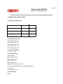
Table of Contents
Page
Service Guide PM3410
0 About This Manual
Front Cover
Manual Copyright
1 Product Specifications
1.1 Overview
1.2 Physical Specifications
1.3 Power Requirements
1.4 Environmental Conditions
1.5 Agency Approvals
1.6 Operational Specifications
1.7 Paper Specifications
1.8 Memory Specifications
1.9 Consumables
1.10 Options
1.11 Reliability
2 Principles of Operation
2.1 Electrical Operation - General Information
....2.1.02 Microprocessor (MPU) and Peripheral Circuits
....2.1.03 Initialization
....2.1.04 Interface Control
....2.1.05 Printhead Drive Circuit
....2.1.06 Spacing Drive Circuit
....2.1.07 Line Feed Circuit
....2.1.08 Alarm Circuits
....2.1.09 Paper End Detection Circuit
....2.1.10 Power Supply
2.2 Mechanical Operation - Printhead Mechanism
....2.2.02 Spacing Mechanism
....2.2.03 Ribbon Drive Mechanism
....2.2.04 Paper Feed Mechanism
....2.2.05 Paper-End Detection Mechanism
....2.2.06 Automatic Paper Loading
....2.2.07 Paper Park Feature
3 Maintenance & Disassembly
3.1 Overview
....3.1.02 Maintenance Items
....3.1.03 Maintenance Precautions
3.2 Disassembly/Assembly Procedures
....3.2.01 Printhead (with Preliminary Items)
....3.2.02 Ribbon Protector Assembly
....3.2.03 Upper Cover Assembly
....3.2.04 Operator Panel
1
2
3
4
5
6
7
8
9
10
11
12
13
14
15
16
17
18
19
20
21
22
23
24
25
26
27
28
29
30
31
32
33
34
35
36
37
38
Table of Contents
....3.2.05 Interface Connector Board
....3.2.06 Main Logic (CBNP) Board
....3.2.07 Printer Mechanism
....3.2.08 Power Supply Unit
....3.2.09 Printer Unit
....3.2.10 BTFD PCB
....3.2.11 Tension Spring
....3.2.12 Bottom Push Mechanism and Front Door Assembly
....3.2.13 Drive Pulley and Belt
....3.2.14 Tractor Assembly (BTF)
....3.2.15 Line Feed Motor (BTF)
....3.2.16 Platen Assembly
....3.2.17 Paper Pressure Guide
....3.2.18 Line Feed Motor Assembly
....3.2.19 Ribbon Cartridge Bracket
....3.2.20 Fan Assembly
....3.2.21 Head Cable Assembly
....3.2.22 Carriage and Carriage Shaft
....3.2.23 Ribbon Feed Assembly
....3.2.24 Space Motor Assembly
....3.2.25 Space Belt
....3.2.26 Sensor Board (LPRW)
....3.2.27 Bail Motor/Gear Assembly
....3.2.28 Paper Bail Assembly
....3.2.29 Rear Feed Tractor Assembly
....3.2.30 Printhead Gap/Release Lever Microswitches
....3.2.31 Release Lever / Gear Assemblies
3.3 Printer Adjustments
....3.3.02 Printhead Gap
....3.3.02 Line Feed Belt Tension
....3.3.03 Key Combinations
....3.3.04 Menu Operation
........Menu Settings
....3.3.05 Top Of Form
....3.3.06 Paper Park
....3.3.07 Forms Tear Off
....3.3.08 Resets
3.4 Cleaning
3.5 Lubrication
....3.5.02 Areas Not Lubricated
....3.5.03 Lubrication Diagrams
........Right and Left Sides of Printer
........Carriage Shaft
........Ribbon Feed Assembly
Page
39
40
41
42
43
44
45
46
47
48
49
50
51
52
53
54
55
56
57
58
59
60
61
62
63
64
65
66
67
68
69
70
71
72
73
74
75
76
77
78
79
80
81
82
Table of Contents
........Space Motor Assembly
........Tractor Feed Assembly
3.6 Shipping Instructions
....3.6.02 All Other Returns
4 Failure & Repair Analysis
4.1 Failure & Repair Analysis - Introduction
....4.1.02 Printer Serial Number Identification
4.2 Reporting Problems
....4.2.02 Problem Lists
....4.2.03 Reporting Methods
4.3 Troubleshooting Updates
4.4 Troubleshooting Tips
....4.4.02 Problem Categories
....4.4.03 START HERE Flowchart
....4.4.04 Tips for Preventing Image Problems
....4.4.05 Common Problems
4.5 Abnormal Output
4.6 Fault Alarms
4.7 Repair Analysis Procedures (RAPS)
....4.7.02 RAP Index
........RAP 01: Power Lamp Does Not Light
........RAP 02: Spacing Error
........RAP 03: Head Homing Error
........RAP 04: Bail Homing Error
........RAP 05: Ribbon Feed Problem
........RAP 06: Wrong Character, Character Omission or Dot
Omission
........RAP 07: Line Feed Problem
........RAP 08: Malfunction of Operator Panel Switch
........RAP 09: Data Receiving Failure
........RAP 10: ALARM Lamp ON
........RAP 11: Bottom Tractor Feed Unit (BTFU) Problem
4.8 Printer Tests - Rolling Ascii Test
....4.8.02 Font Sample Test
........Sample - Part 1
........Sample - Part 2
....4.8.03 Serial Interface Diagnostic
....4.8.04 Hexadecimal Dump
4.9 Resistance Checks
....4.9.02 Printhead
....4.9.03 Line Feed Motor
....4.9.04 Space Motor
....4.9.05 Bail Motor
A Board Diagrams
Page
83
84
85
86
87
88
89
90
91
92
93
94
95
96
97
98
99
100
101
102
103
104
105
106
107
108
109
110
111
112
113
114
115
116
117
118
119
120
121
122
123
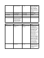
Table of Contents
A.1 Overview
A.2 Index To Charts
....A.2.01 Main Logic Board (CBNP)
....A.2.02 Power Supply Board
....A.2.03 Interface Board (HKTY)
....A.2.04 Sensor Board (LPRW)
....A.2.05 Operator Panel Board (OPML)
....A.2.06 Bottom Tractor Feed Unit Board (BTFD)
B Illustrated Parts Listing
B.1 Overview
....B.1.02 Definition of Terms
....B.1.03 Parts Ordering Information
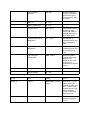
B.2 Charts
....B.2.01 Printer
....B.2.02 Upper Cover Assembly
....B.2.03 Printer Unit
....B.2.04 Operator Panel Assembly
....B.2.05 Carriage Assembly
....B.2.06 Printer Mechanism (1 of 2)
....B.2.07 Printer Mechanism (2 of 2)
....B.2.08 Bottom Tractor Feed Unit
....B.2.09 Options
....B.2.10 Pull Tractor Unit (Option)
....B.2.11 Packing Materials
....B.2.12 Consumables
....B.2.13 Documentation
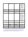
Page
124
125
126
127
128
129
130
131
132
133
134
135
136
137
138
139
140
141
142
143
144
145
146
147
148
Page: 2
Service Guide PM3410
Chapter 0 About This Manual
This document may not be reproduced without the written permission of the Okidata® Technical
Training Group. Every effort has been made to ensure the accuracy of the information contained
in this training course. Okidata is not responsible for errors beyond its control.
© 1994 by Okidata All rights reserved.
First Edition January, 1992
P/N 59249701
Second Edition October, 1994
P/N 59249702
Written and produced by the Okidata Technical Training Group
Please address any comments on this publication to:
Technical Training Group
Okidata
532 Fellowship Road
Mount Laurel, NJ 08054-3499
Fax Number: (609) 235-2600, ext. 7034
Okilink Login Name: Technical Training
OKIDATA is a registered trademark of Oki Electric Industry Company, Ltd.; marques deposee de
Oki Electric Industry Company, Ltd.; marca registrada, Oki Electric Industry Company, Ltd.
MICROLINE is a trademark of Oki Electric Industry Company, Ltd.
PACEMARK is a trademark of Oki Electric Industry Company, Ltd.
IBM and Proprinter are registered trademarks of International Business Machines Corporation.
Centronics is a registered trademark of the Centronics Corporation
Epson and Epson FX are registered trademarks of Seiko Epson Corporation
Copyright 1997, Okidata, Division of OKI America, Inc. All rights reserved. See the OKIDATA Business
Partner Exchange (BPX) for any updates to this material. (http://bpx.okidata.com)
Page: 3
Service Guide PM3410
Chapter 1 Product Specifications
1.1 OVERVIEW
1.1.01 General Information
The Pacemark 3410 is a high speed, dot matrix printer, which utilizes a 9 pin printhead.
The printer is capable of emulating the IBM Proprinter or the Epson FX printers.
The Pacemark 3410 comes standard with both an RS232-C Serial Interface and a Centronics Parallel
Interface. Also standard is the bottom push tractor feed unit.
Copyright 1997, Okidata, Division of OKI America, Inc. All rights reserved. See the OKIDATA Business
Partner Exchange (BPX) for any updates to this material. (http://bpx.okidata.com)
Page: 4
Service Guide PM3410
Chapter 1 Product Specifications
1.2 PHYSICAL SPECIFICATIONS
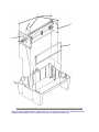
1.2.01 Printer Dimensions
NOTE:
Dimensions include the bottom feed unit.
Width: 25.5 inches (54.0 centimeters)
Depth: 19 inches (48.3 centimeters)
Height: 15 inches (20.3 centimeters)
1.2.02 Printer Weight
63 pounds (25.4 kilograms)
United Parcel Service (UPS) shippable
Copyright 1997, Okidata, Division of OKI America, Inc. All rights reserved. See the OKIDATA Business
Partner Exchange (BPX) for any updates to this material. (http://bpx.okidata.com)
Page: 5
Service Guide PM3410
Chapter 1 Product Specifications
1.3 POWER REQUIREMENTS
1.3.01 Input Power
Input Voltage
120 VAC +5.5%, -15%
220/240 +10%, -10%
Frequency
50/60 hz. +/-2%
1.3.02 Power Consumption
Operating: 75 W
Idle: 30 W
Copyright 1997, Okidata, Division of OKI America, Inc. All rights reserved. See the OKIDATA Business
Partner Exchange (BPX) for any updates to this material. (http://bpx.okidata.com)
Page: 6
Service Guide PM3410
Chapter 1 Product Specifications
1.4 ENVIRONMENTAL CONDITIONS
1.4.01 Acoustic Rating
58.5 dBa
1.4.02 Altitude
10,000 feet (3,048 meters)
1.4.03 Ambient Temperature and Relative Humidity
In Operation
41 to 95 degrees Fahrenheit (5 to 35 degrees Celsius)
@ 20% - 80% Relative Humidity
In Storage
14 to 122 degrees Fahrenheit (-10 to 50 degrees Celsius)
@ 5% - 95% Relative Humidity
Copyright 1997, Okidata, Division of OKI America, Inc. All rights reserved. See the OKIDATA Business
Partner Exchange (BPX) for any updates to this material. (http://bpx.okidata.com)
Page: 7
Service Guide PM3410
Chapter 1 Product Specifications
1.5 AGENCY APPROVALS
1.5.01 Listings
North America
FCC Class B
UL 478 (Office Machines and Business Equipment)
CSA 22.2 (220)
Copyright 1997, Okidata, Division of OKI America, Inc. All rights reserved. See the OKIDATA Business
Partner Exchange (BPX) for any updates to this material. (http://bpx.okidata.com)
Page: 8
Service Guide PM3410
Chapter 1 Product Specifications
1.6 OPERATIONAL SPECIFICATIONS
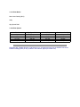
1.6.01 Character Matrix Sizes
Print Mode
Horizontal
Vertical
Near Letter Quality
24
17
Utility
12
9
High Speed Draft
9
9
1.6.02 Characters Per Line
136 Characters @ 10 cpi
163 Characters @ 12 cpi
204 Characters @ 15 cpi
233 Characters @ 17.1 cpi
272 Characters @ 20 cpi
1.6.03 Character Pitches
10, 12, 15, 17.1, 20
1.6.04 Character Sets
Standard ASCII
Epson Character Set I
Epson Character Set II
IBM Character Set I
IBM Character Set II
IBM ALL (Proprinter) Character Set
Foreign Language Substitution (International Characters)
Line Graphics
Code Pages: 850, 863
1.6.05 Emulations
NOTE:
The Plug-in Chip Set for Microline/Pacemark Emulation is installed by a technician.
Resident
Epson FX-1050
IBM Proprinter III
Optional Plug-in Chip Set
Microline/Pacemark
1.6.06 Fonts
Standard
Near Letter Quality
Courier
Gothic
Proportional
Draft
Utility
High Speed Draft
Custom Characters
Barcode
Code 128 (ABC)
Code 3 of 9
EAN 8
EAN 13
Interleaved 2 of 5
POSTNET
UPC-A
UPC-E
1.6.07 Front Panel Switches
Select
Paper Park
Menu Mode
Pitch Selection
Line Feed
Print Quality Selection
Form Feed
Tear
Top of Form
Micro Feed Up / Down
1.6.08 Graphics Resolution
Maximum: 240 x 216 dots per inch (dpi)
1.6.09 Interface Methods
Standard
Centronics Parallel Interface
RS232-C Serial Interface (19.2 KB)
Optional
Twin-ax or Co-ax
Available from a third party vendor. Call 1-800-OKIDATA [1-800-654-3282] for more information.
1.6.10 Line Feed Increments
1/6" (Selected through the Menu)
1/8" (Selected through the Menu)
n/72"
n/144"
n/216"
1.6.11 Line Feed Time
10.0 Inches Per Second (IPS) slew rate (when Printhead Gap Lever is set at 1 or 2)
6 IPS slew rate (when Printhead Gap Lever is set at 3 or 4)
5 IPS slew rate (when Printhead Gap Lever is set at 5 through 9)
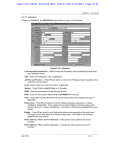
1.6.12 Menu Mode
Print: Prints the entire menu.
Group: Selects Group Function
Item: Selects Item
Set: Selects Item Value
Exit: Exits Menu Mode, Enters Select
1.6.13 Paper Feed Methods
Built-in Push Tractor (Bottom)
Built-in Push Tractor (Rear)
Friction Feed (Top)
Bottom Push Tractor Feed Unit
Optional Pull Tractor (Bottom / Rear)
Optional Cut Sheet Feeders (Single and Dual Bin)
1.6.14 Paper Feed Paths
Bottom Feed
Rear Feed
Top Feed
Special Features
Paper Park
Automatic Paper Loading
Forms Tear Off
1.6.15 Paper Loading
Auto Bail Arm for Auto Loading
1.6.16 Paper Out Detection
Distance from end of paper
Rear Feed: 2.30 inches (58.42 mm)
Bottom Feed: .94 inches (23.88 mm)
Cut Sheet: .93 inches (23.62 mm)
1.6.17 Paper Tear Capabilities
Form Tear-Zero Tear
Metal Tear Bar
1.6.18 Print Method
Printhead Type
General Information
Impact, Dot Matrix
Staggered, 9 pin, stored energy printhead
0.36 mm diameter pins
Installed by Service Technician
The Printhead Gap Adjustment must be performed when the printhead is replaced.
Overheat Protection
When the printhead temperature reaches 115 degrees Celsius, the printer stops bi-directional printing. Uni-directional printi
If the temperature continues to rise (125° Celsius), printing stops.
Printing will resume when the printhead temperature drops below 115 degrees Celsius.
1.6.19 Print Modes
Near Letter Quality (NLQ)
Utility
High Speed Draft
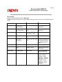
1.6.20 Print Speeds
Pitch
10 cpi
12 cpi
15 cpi
17.1 cpi
20 cpi
High Speed Draft
550 cps
550 cps
550 cps
550 cps
550 cps
Utility
417 cps
417 cps
417 cps
417 cps
417 cps
Near Letter Quality
104 cps
104 cps
104 cps
104 cps
104 cps
Copyright 1997, Okidata, Division of OKI America, Inc. All rights reserved. See the OKIDATA Business
Partner Exchange (BPX) for any updates to this material. (http://bpx.okidata.com)
Page: 9
Service Guide PM3410
Chapter 1 Product Specifications
1.7 PAPER SPECIFICATIONS
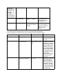
1.7.01 Types
Card Stock
Weight: 120 lbs. (450 g/m 2 ) Maximum
Width: 5 to 14 inches (12.7 to 35.6 centimeters)
Length: 3 to 17 inches (7.62 to 43.18 centimeters)
Thickness: .02 inches (0.5 millimeters)
Paper Feed Path: Bottom
Head Gap Lever Setting: 8 - 9
Continuous Form
Weight:
Single Part 12 - 24 lb. (45 to 90 g/m 2 )
Multi-Part, Carbonless 9 - 11 lb. (35 to 40 g/m 2 )
Multi-Part, Interleaf Paper 10 - 12 lb. (38 to 45 g/m 2 ) Carbon 9 lb. (35 g/m 2 )
Width: 3 to 16 inches (76.2 to 406.4 millimeters)
Length: 3 to 17 inches (7.62 to 43.18 centimeters)
Thickness: 0.014 inches (0.36 millimeters) Rear Feed 0.02 inches (0.5 millimeters) Bottom Feed
Paper Feed Path: Rear or Bottom
Head Gap Lever Setting: 1 Single Part 12 - 15 lb. (45 to 56 g/m 2 )
1 - 2 Single Part 20 - 24 lb. (75 to 90 g/m 2 )
2 - 3 Two Part
3 - 4 Three Part
5 Four Part
6 Five Part
7 Six Part
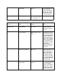
Cut Sheet
Weight: 12 to 24 lbs. (45 to 90 g/m 2 )
Width: 7.2 to 14.3 inches (18.3 to 36.3 centimeters)
Length: 3 to 17 inches (7.62 to 43.18 centimeters)
Thickness: 0.014 inches (0.325 millimeters) Maximum
Paper Feed Path: Top
Head Gap Lever Setting: 1 12 - 15 lb. (45 to 56 g/m 2 )
1 - 2 20 - 24 lb. (75 to 90 g/m 2 )
Envelopes
Weight: 24 lbs. (90 g/m 2 ) Maximum
Size:
Single Feed
Minimum: 6.5 x 3.6 inches (16.5 x 9.1 centimeters)
Maximum: 9.5 x 4.1 inches (24.1 x 10.4 centimeters)
Continuous
Non-overlap type
Thickness: .014 inches (.325 millimeters) Maximum
Paper Feed Path: Bottom
Head Gap Lever Setting: 5 - 9
Labels
Weight: N/A
Width: 3 to 16 inches (7.62 to 40.64 centimeters)
Length: 3 to 17 inches (7.62 to 43.18 centimeters)
Thickness: .011 inches (0.28 mm) Maximum (including backing)
Paper Feed Path: Bottom
Head Gap Lever Setting: 3 - 4
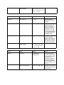
Transparency
NOTE:
Roller marks may mar the transparency under high temperature / high humidity conditions.
Weight: 12 to 24 lbs. (45 to 90 g/m 2 )
Width: 7.2 to 14.3 inches (18.3 to 36.3 centimeters)
Length: 3 to 17 inches (7.62 to 43.18 centimeters)
Thickness: 0.14 inches (0.36 millimeters)
Paper Feed Path: Top
Head Gap Lever Setting: 1 12 - 15 lb.
1 - 2 20 - 24 lb.
1.7.02 Length
NOTE:
The recommended length is specific to paper type.
Rear Feed
Minimum 3 inches (7.62 centimeters)
Maximum 17 inches (43.18 centimeters)
Bottom Feed
Minimum 3 inches (7.62 centimeters)
Maximum 17 inches (43.18 centimeters)
Top Feed
Minimum 3 inches (7.62 centimeters)
Maximum 17 inches (43.18 centimeters)
1.7.03 Number of Copies
Original + 5 Interleaf
Original + 7 Carbonless
Original + 3 Cut Sheet (top edge must be glued tight)
1.7.04 Thickness
0.014 inches / 0.36 mm Maximum Thickness, Rear Feed
0.020 inches / 0.50 mm Maximum Thickness, Bottom Feed
1.7.05 Weight
NOTE:
The recommended weight is specific to paper type.
Minimum: 9 lb. (35 g/m 2 )
Maximum: 24 lb. (90 g/m 2 )
1.7.06 Width
NOTE:
The recommended width is specific to paper type.
Minimum: 3 inches
Maximum: 16 inches
Copyright 1997, Okidata, Division of OKI America, Inc. All rights reserved. See the OKIDATA Business
Partner Exchange (BPX) for any updates to this material. (http://bpx.okidata.com)
Page: 10
Service Guide PM3410
Chapter 1 Product Specifications
1.8 MEMORY SPECIFICATIONS
1.8.01 EEPROM
Internal Control, Menu = 256 bits
1.8.02 RAM
Total RAM = 64 Kbytes
Print Buffer = 28 Kbytes
DLL Buffer = 0 to 31 Kbytes
1.8.03 ROM
Resident: Program ROM = 256 Kbytes
Copyright 1997, Okidata, Division of OKI America, Inc. All rights reserved. See the OKIDATA Business
Partner Exchange (BPX) for any updates to this material. (http://bpx.okidata.com)
Page: 11
Service Guide PM3410
Chapter 1 Product Specifications
1.9 CONSUMABLES
1.9.01 Ribbon
Black Cartridge
Type: Nylon Fabric
Ribbon Life: Approximately 7.5 million characters
Copyright 1997, Okidata, Division of OKI America, Inc. All rights reserved. See the OKIDATA Business
Partner Exchange (BPX) for any updates to this material. (http://bpx.okidata.com)
Page: 12
Service Guide PM3410
Chapter 1 Product Specifications
1.10 OPTIONS
1.10.01 Cut Sheet Feeders
CSF 3001 Single Bin
and
CSF 3002 Dual Bin
14 inches wide
User installable
Sheet Capacity
170 sheets of 16 lb.
100 sheets 24 lb.
Paper Width
7.2 to 8.5 inches (18.3 to 21.6 centimeters)
Paper Length
10.1 to 14 inches (25.7 to 35.6 centimeters)
1.10.02 Pull Tractor with Acoustic Cover
Use with bottom feed for continuous forms, labels, and / or invoices.
1.10.03 Microline/Pacemark Emulation Chip Set
Technician installable
1.10.04 Printer Stands
Available through a Third Party Vendor.
For more information, please call
800-749-2258 (Pacemark ONLY)
800-827-2672 (all printers)
1.10.05 Twin-ax / Co-ax
Available through a Third Party Vendor.
For more information, please call 508-777-7957.
Copyright 1997, Okidata, Division of OKI America, Inc. All rights reserved. See the OKIDATA Business
Partner Exchange (BPX) for any updates to this material. (http://bpx.okidata.com)
Page: 13
Service Guide PM3410
Chapter 1 Product Specifications
1.11 RELIABILITY
1.11.01 Mean Time Before Failure (MTBF)
Approximately 8,000 hours @ 25% Duty Cycle, 35% Page Density
Approximately 2,000 hours @ 100% Duty Cycle
1.11.02 Mean Time To Repair (MTTR)
Approximately 15 minutes @ major sub-assembly level
1.11.03 Printer Life
Approximately 16,000 Hours @ 25% Duty Cycle, 35% Page Density
1.11.04 Printhead Life
Approximately 200,000,000 characters (average)
@ 10 cpi Draft Mode @ 25% Duty Cycle, 35% Page Density
1.11.05 Ribbon Life
Approximately 7.5 million characters
1.11.06 Warranty (Limited)
One year parts, labor, printhead
1.11.07 Service
90 days, on-site
Copyright 1997, Okidata, Division of OKI America, Inc. All rights reserved. See the OKIDATA Business
Partner Exchange (BPX) for any updates to this material. (http://bpx.okidata.com)
Page: 14
Service Guide PM3410
Chapter 2 Principles of Operation
2.1 ELECTRICAL OPERATION
2.1.01 General Information
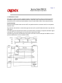
The main logic board consists of the microprocessor, its peripheral LSI circuits, ROM, DRAM and the
drive circuits. The voltages for the main logic board are supplied by the power supply unit. The voltages for
the various electrical components (motors, sensors, etc.) are distributed from the main logic board.
Copyright 1997, Okidata, Division of OKI America, Inc. All rights reserved. See the OKIDATA Business
Partner Exchange (BPX) for any updates to this material. (http://bpx.okidata.com)
Page: 15
Service Guide PM3410
Chapter 2 Principles of Operation
2.1.02 Microprocessor (MPU) and Peripheral Circuits
Microprocessor
Q3: M67X640V1
The MicroProcessor Unit (MPU) is the nucleus of the control circuit. Various peripheral circuits operate
under program control of this microprocessor. The MPU (Q3) controls all aspects of printer operation.
Program ROM for the MPU
Q4: 27C202K
This 2Mbit Read Only Memory (ROM) contains the control program for the printer. The MPU operates
under program control.
This ROM also stores the resident character fonts.
DRAM
Q10 and Q11
The Dynamic Random Access Memory (RAM) chips, each consisting of 64 K x 4 bits, are used as the
Command Buffer, Receive Buffer and Print Buffer.
The total buffer size is 64 K x 8 bits. The RAM speed is 120 ns.
EEPROM
Q14: 93C06N
This 256-bit serial Electrically Erasable and Programmable Read Only Memory (EEPROM) stores the
menu data and initial settings for the LSI circuits.
Interface/Motor Control LSI
Q5: B562 13497
This LSI controls the following functions listed below.
Space Motor Enable / Speed Control
To obtain the carriage speed instructed by the microprocessor, Q5 uses the signals SP - Phase A and SP
- Phase B, derived from space motor movement to generate the pulse width timing and overdrive time.
Line Feed Motor Phasing Control
To turn the line feed motor in the proper direction, this LSI sends motor drive signals (properly phased) to
the line feed driver (TRA4).
Bail Motor Phasing Control
To turn the bail motor in the proper direction, this LSI sends motor drive signals (properly phased) to the
bail driver (TRA3).
Dot ON Timing signal generation
Q5 uses the signals SP - Phase A and SP - Phase B, derived from space motor movement, to produce
the signal IPT. This signal (IPT) is used to enable the print wires at the desired carriage position.
Printhead / Bottom Tractor Feed Control LSI
Q2: B563 12597
This LSI enables the printhead drivers and is the interface between the bottom tractor feed unit (BTFD
PCB) and the MPU.
The functions of this LSI are described below.
Printhead Drive Control
Printhead drive correction modifies the drive time under the following circumstances:
Drive time correction for drive voltage fluctuations
Drive time correction for head gap setting.
Bottom tractor feed unit control
Copyright 1997, Okidata, Division of OKI America, Inc. All rights reserved. See the OKIDATA Business
Partner Exchange (BPX) for any updates to this material. (http://bpx.okidata.com)
Page: 16
Service Guide PM3410
Chapter 2 Principles of Operation
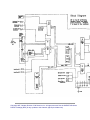
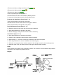
2.1.03 Initialization
The printer is initialized whenever it is powered ON or when the I-PRIME signal is received from the host
at the parallel interface.
The initialization process is performed as listed below.
1. The reset circuit sends the RST-P signal to the MPU and LSIs.
2. ROM program execution starts with the mode setting of Q2 and Q5.
3. ROM and RAM are checked for errors.
4. RAM is initialized.
5. Bail and carriage homing is performed.
6. The interface signals (output level of ACK, BUSY, etc.) are set.
7. The SELECT lamp is turned ON.
8. The printer signals the host computer that it is ready to receive data.
Block Diagram
Copyright 1997, Okidata, Division of OKI America, Inc. All rights reserved. See the OKIDATA Business
Partner Exchange (BPX) for any updates to this material. (http://bpx.okidata.com)
Page: 17
Service Guide PM3410
Chapter 2 Principles of Operation
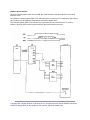
2.1.04 Interface Control
The printer is capable of serial or parallel operation. The desired interface method is selected by sliding
the interface cover to expose the desired connector. When this is done, the interface select switch is
turned ON or OFF to inform the Interface/Motor Control LSI (Q5: B562 13497) of the selected interface.
Parallel Interface
When the interface select switch is turned OFF, the parallel interface is selected and Q5 is in the parallel
interface mode.
The data from the interface is received through connector (CN-1) and Q5 latches this data in sync with the
STB signal.
The BUSY signal is turned ON as the data is processed. When processing is completed, the BUSY signal
is turned OFF and an ACK signal is sent to the host to request more data.
The BUSY signal is also turned ON when the printer is not able to receive data (the Print Buffer is full, the
printer is deselected or an error condition exists).
RS232-C Serial Interface
When the interface select switch is turned ON, the serial interface is selected and Q5 is in the serial
interface mode.
The RS232-C interface signals (DSR, CTS, CD and RD) are converted to TTL levels by the line receiver
(Q13) and input to Q5 where the serial data is converted to parallel data.
The interface signals (DTR, RTS, SSD and TD) output from Q5 are converted from TTL levels to
RS232-C levels by the line driver (Q12) and sent to the serial interface connector.
Copyright 1997, Okidata, Division of OKI America, Inc. All rights reserved. See the OKIDATA Business
Partner Exchange (BPX) for any updates to this material. (http://bpx.okidata.com)
Page: 18
Service Guide PM3410
Chapter 2 Principles of Operation
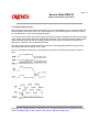
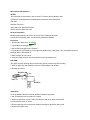
2.1.05 Printhead Drive Circuit
This circuit is used to drive the 9 print wires. The signals HD01 through HD09 from Q2 are used to enable
the individual wire drivers (TRA1 and TRA2). TRA1 drives Pins 1, 2, 6 and 7. TRA2 drives Pins 3, 4, 8 and
9. TR7 drives Pin 5. The HD ON signal enables the drive circuit when printing is desired. The head drive
duration is determined by an RC integrating circuit which modifies the HD ON pulsewidth. The pulsewidth
of the HD ON signal varies with the number of pins being driven. The drive time is increased as a greater
number of pins are driven, but decreased as less pins are to be driven. The drive time is also increased if
the head gap lever in placed in positions 3 through 9. The RC circuit is also used to compensate for the
fluctuation of drive voltage (+38vdc).
Copyright 1997, Okidata, Division of OKI America, Inc. All rights reserved. See the OKIDATA Business
Partner Exchange (BPX) for any updates to this material. (http://bpx.okidata.com)
Page: 19
Service Guide PM3410
Chapter 2 Principles of Operation
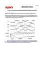
2.1.06 Spacing Drive Circuit
After receiving a spacing command from the MPU (Q3), the Interface/Motor Control LSI (Q5) outputs the
SPFWD signal to run the DC motor in the forward direction, or the SPRVS signal to run the DC motor in
the reverse direction. This is a fixed pulsewidth signal.
To control the motor speed, Q5 varies the pulse duty cycle according to feedback received from the space
motor. As the space motor rotates, the SPSP Board (inside the motor housing) generates feedback pulse
signals SPfA and SPfB. Q5 detects the edge pulses from these signals and divides the frequency to
output the IPT signal for use in printhead dot timing.
The space motor interlock switch (located at the left side of the shield plate) disables the space motor
drive signals whenever the printer cover is open.
Fuse F1 (3.5 amperes) protects the +38vdc space motor power circuit, should an overdrive condition
exist.
Copyright 1997, Okidata, Division of OKI America, Inc. All rights reserved. See the OKIDATA Business
Partner Exchange (BPX) for any updates to this material. (http://bpx.okidata.com)
Page: 20
Service Guide PM3410
Chapter 2 Principles of Operation
2.1.07 Line Feed Circuit
Whenever it is in a stopped position, the line feed motor shaft is held stationary by +8vdc, which is
enabled by the LFCHOP Signal from Q2. The holding current is approximately 30 ma.
During a line feed operation, the line feed motor is driven by +38 vdc in accordance with the LFOVDV
signal. The signals LF - Phase 01 and LF - Phase 04 establish the proper phase relationship for driving
the motor. However, the line feed motor uses Phase 1 - 4.
Copyright 1997, Okidata, Division of OKI America, Inc. All rights reserved. See the OKIDATA Business
Partner Exchange (BPX) for any updates to this material. (http://bpx.okidata.com)
Page: 21
Service Guide PM3410
Chapter 2 Principles of Operation
2.1.08 Alarm Circuits
Fault Alarm Circuit (in Power Supply Unit)
This protective circuit turns off the power supply when a fault occurs in the printhead, line feed, or bail
motor drive circuits, thus preventing secondary component failure.
To accomplish this, the circuit monitors the overdrive signal of each drive circuit. If the duration of any
drive circuit exceeds a predetermined length of time, the appropriate signal (EVN COM, ODD COM, LF
COM or BM COM) will be sent to the fault alarm circuit. The fault alarm circuit generates the ALM signal
which causes the power supply to turn all DC power OFF.
Printhead Overheat Alarm Circuit
In order to protect the printhead coils, this circuit monitors the printhead temperature by using a thermistor
contained in the printhead. The CPU senses this circuit every time a line is printed.
When printing, the printhead temperature will increase. If the head temperature reaches approximately
115° Celsius, a head overheat ALARM 1 is generated. When ALARM 1 is detected by the MPU, the
printer will begin unidirectional printing. If the printhead temperature increases to 125° Celsius, ALARM 2
is generated and printing is halted until the head temperature decreases. When the head temperature
returns below the ALARM 1 threshold, printing is resumed.
Cover Open Alarm Circuit
When the front access cover is opened, the CVOPEN-N signal is sent to the MPU from the cover interlock
microswitch. The MPU will halt printing immediately and light the ALARM Lamp.
Copyright 1997, Okidata, Division of OKI America, Inc. All rights reserved. See the OKIDATA Business
Partner Exchange (BPX) for any updates to this material. (http://bpx.okidata.com)
Page: 22
Service Guide PM3410
Chapter 2 Principles of Operation
2.1.09 Paper End Detection Circuit
NOTE:
Paper End is also known as paper out
Whenever the release lever is in the Tractor (Continuous) Feed position, paper end is detected by the
microswitch on the push tractor (rear feed) or the paper end sensor on the sensor board (bottom feed).
Whenever the release lever is in the Friction (Sheet) Feed position, Paper End is detected by a
photosensor (top feed) located in the paper pressure guide.
When the printer detects an out of paper condition, the PEN (Paper End) signal goes low, the printing is
stopped and the ALARM LAMP is turned ON.
Copyright 1997, Okidata, Division of OKI America, Inc. All rights reserved. See the OKIDATA Business
Partner Exchange (BPX) for any updates to this material. (http://bpx.okidata.com)
Page: 23
Service Guide PM3410
Chapter 2 Principles of Operation
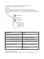
2.1.10 Power Supply
This switching power supply converts the AC input voltage to +5vdc, +/-8vdc and +38 vdc for use
throughout the printer.
Voltage / Signal Table
Voltage/Signal
Purpose
+5 vdc
IC logic Levels - LED Drive Voltage
+8 vdc
Serial Interface logic Levels - Line Feed Motor Locking Voltage
-8 vdc
Serial Interface logic Levels
+38 vdc
Printhead Space Motor Line Feed Motor Bail Motor Drive Voltage
POW ALM
Output from the Power Supply in the event of an abnormal temperature rise in the
power supply unit or an overcurrent condition of the +38 vdc. The main logic
board suppresses this condition by temporarily suspending printing. If the
condition does not change the main logic board will enable the FAN ALARM.
Refer to Section 4 - Failure Analysis
ALM
Input from the main logic board upon detection of an overdrive condition in the
printhead line feed motor or bail motor drive circuits. Upon detecting this signal
the power supply disables the +38 vdc output.
Copyright 1997, Okidata, Division of OKI America, Inc. All rights reserved. See the OKIDATA Business
Partner Exchange (BPX) for any updates to this material. (http://bpx.okidata.com)
Page: 24
Service Guide PM3410
Chapter 2 Principles of Operation
2.2 MECHANICAL OPERATION
2.2.01 Printhead Mechanism
The printer uses a highly efficient stored energy type printhead. Power is not consumed until the printwires
are activated, thereby extending the printhead life to approximately 200 million characters.
The printhead uses 9 printwires in two columns. Each wire is welded to an armature. Behind this armature
is a spacer ring.
Each of the 9 printwire armatures has a permanent magnet behind it. The magnets attract the armatures,
pulling the printwires into the wire guide, thus keeping the wires inside the printhead. A coil is wrapped
around each of the permanent magnets.
When a dot is to be printed, current is passed through the appropriate coil. This creates an
electromagnetic field which counters the magnetic field of the permanent magnet. The armature can then
spring forward and the print wire (which is attached to the armature) strikes the ribbon and imprints a dot
on the paper.
When current is removed from the coil, the magnetic field of the permanent magnet attracts the armature,
causing the printwire to retract into the wire guide once again.
The printhead consists of the parts listed below.
Wire Guide
Print Wires
Armature Assembly
Spacer
Permanent Magnet Assembly
Thermistor: used to monitor the printhead temperature
Printed Circuit board with Coils
Head Gap Adjusting
The head gap adjusting mechanism modifies the gap between the platen and printhead. This is
accomplished by moving the adjusting lever on the right side of the printer mechanism. When the lever is
moved, the carriage shaft rotates. Since the carriage shaft is attached to the printer mechanism through
eccentric collars, turning the carriage shaft, changes the distance between the platen and the printhead.
Copyright 1997, Okidata, Division of OKI America, Inc. All rights reserved. See the OKIDATA Business
Partner Exchange (BPX) for any updates to this material. (http://bpx.okidata.com)
Page: 25
Service Guide PM3410
Chapter 2 Principles of Operation
2.2.02 Spacing Mechanism
Spacing is performed when the servo motor drives the carriage along the carriage shaft, parallel to the
platen.
The spacing mechanism consists of the following items.
DC (Servo) Motor
Idle Pulley
Carriage Shaft
Carriage Frame
Space Belt
Spacing Operation
The carriage containing the printhead moves parallel to the platen along the carriage shaft. Power from
the space motor is transferred via the space belt, which is attached to the bottom of the carriage. The
carriage is designed to move 1.6 inches when the servo motor performs one rotation.
Copyright 1997, Okidata, Division of OKI America, Inc. All rights reserved. See the OKIDATA Business
Partner Exchange (BPX) for any updates to this material. (http://bpx.okidata.com)
Page: 26
Service Guide PM3410
Chapter 2 Principles of Operation
2.2.03 Ribbon Drive Mechanism
The ribbon drive mechanism moves the ribbon in synchronization with the space motor operation.
The ribbon drive mechanism consists of the items listed below.
Ribbon Drive Assembly
Ribbon Cartridge
Ribbon Cartridge
An endless ribbon with a single direction feed is used. Ink is supplied from an ink tank, which is contained
in the ribbon cartridge.
Ribbon Feed Operation
The rotation of the space motor is transmitted to the drive gear in the ribbon cartridge through the ribbon
feed gear assembly, thereby feeding the ink ribbon.
The feed direction of the ribbon is maintained by switching the rotational direction of the gears in the
ribbon drive assembly. This ensures unidirectional ribbon movement when bi-directional printing is used.
Copyright 1997, Okidata, Division of OKI America, Inc. All rights reserved. See the OKIDATA Business
Partner Exchange (BPX) for any updates to this material. (http://bpx.okidata.com)
Page: 27
Service Guide PM3410
Chapter 2 Principles of Operation
2.2.04 Paper Feed Mechanism
Paper feeding is performed by turning the platen and the tractors, which are driven by the line feed pulse
motor.
The paper feed mechanism consists of the items listed below.
Line Feed (Pulse) Motor with gears
Idle Gear
Change Spring
Change Gear
Platen
Push Tractor Assembly
Bottom Tractor Feed Unit
Paper Pressure Guide
Friction (Sheet) Feed
When the release lever is set to the SHEET FEED position, the change gear is disengaged from the
tractor gear. At the same time, the release lever applies pressure to push the pressure rollers against the
platen, allowing paper to be fed.
A photosensor located in the paper pressure guide detects PAPER END.
Tractor (Continuous) Feed
When the Release Lever is set to the TRACTOR FEED position, the release lever allows the reset spring
to push the change gear toward the tractor gear. At the same time, the release lever pushes the pressure
rollers away from the platen, allowing paper to be fed by the tractors.
The microswitch on the push tractor (rear feed) and the paper end sensor on the sensor board (bottom
feed) detect PAPER END.
Copyright 1997, Okidata, Division of OKI America, Inc. All rights reserved. See the OKIDATA Business
Partner Exchange (BPX) for any updates to this material. (http://bpx.okidata.com)
Page: 28
Service Guide PM3410
Chapter 2 Principles of Operation
2.2.05 Paper-End Detection Mechanism
Friction Feed (Cut-Sheet) Paper-End
When the Release Lever is in the SHEET FEED Position, the photosensor located in the Paper Pressure
Guide is active. If sheet paper is installed, the paper is detected by the sensor and the sensor is turned
ON. When the printer is out of sheet paper, the sensor is turned OFF indicating a paper-end condition.
Continuous (Bottom) Feed Paper-End
(Also used with Bottom Tractor Feed Unit)
When the Release Lever is in the TRACTOR FEED Position, the switch on the left Push Tractor and the
Paper-End sensor on the sensor board are active. If paper is detected by either of these sensors,
paper-end is inhibited.
When bottom feed paper is installed, it moves the bottom paper-end lever to turn the sensor ON. When a
paper out condition exists, the lever blocks the sensor, indicating a paper-end condition.
Continuous (Rear) Feed Paper-End
When the Release Lever is in the TRACTOR FEED Position, the switch on the left Push Tractor and the
Paper-End sensor on the sensor board are active. If paper is detected by either of these sensors,
Paper-End is inhibited.
When rear feed paper is installed, pressure is placed on the microswitch, located in the left push tractor.
Since the switch is turned ON, paper is detected.
Copyright 1997, Okidata, Division of OKI America, Inc. All rights reserved. See the OKIDATA Business
Partner Exchange (BPX) for any updates to this material. (http://bpx.okidata.com)
Page: 29
Service Guide PM3410
Chapter 2 Principles of Operation
2.2.06 Automatic Paper Loading
Automatic Paper Loading is used to consistently set the print start position when using cut-sheet or
continuous sheet paper. The autoloading procedures for each type of paper follow.
Cut-Sheet Paper
1. Push the paper release lever to the cut-sheet position.
2. Insert the paper from behind the platen.
3. Press the FORM FEED switch.
4. The paper bail will automatically open.
5. The line feed operation will load the paper.
6. The paper bail will automatically close.
NOTE:
If the paper does not move, the Auto-Load motion becomes invalid and is treated like an ordinary
paper-end condition.
Continuous Sheet (Rear Feed) SASF
1. Push the paper release lever to the continuous sheet side (front of printer).
2. Insert the paper into the push tractor. The white guide line on the left tractor MUST be visible.
3. Press the FORM FEED switch.
4. The paper bail will automatically open.
5. The line feed operation will load the paper.
6. The paper bail will automatically close.
NOTE:
If the paper does not move, the auto-load motion becomes invalid and is treated like an ordinary
paper-end condition.
Copyright 1997, Okidata, Division of OKI America, Inc. All rights reserved. See the OKIDATA Business
Partner Exchange (BPX) for any updates to this material. (http://bpx.okidata.com)
Page: 30
Service Guide PM3410
Chapter 2 Principles of Operation
2.2.07 Paper Park Feature
Occasionally, the user will want to print on cut-sheet paper, and continuous feed paper is loaded in the
printer. Rather than unloading the continuous feed paper, the operator can use the paper park feature.
Paper Park retracts the continuous feed paper until a paper-end condition exists or until 14 inches of
paper has been retracted. The continuous feed paper remains on the push tractor (or bottom tractor feed
unit), but out of the printing path. This allows cut-sheet paper to be loaded. Once the cut-sheet printing is
complete, the continuous feed paper is reloaded.
CAUTION:
Do not attempt to PARK labels or more than one sheet of paper
Copyright 1997, Okidata, Division of OKI America, Inc. All rights reserved. See the OKIDATA Business
Partner Exchange (BPX) for any updates to this material. (http://bpx.okidata.com)
Page: 31
Service Guide PM3410
Chapter 3 Maintenance & Disassembly
3.1 OVERVIEW
3.1.01 General Information
This section lists the parts replacement, adjustment, cleaning, lubrication, and shipping procedures.
Disassembly should not be performed unless absolutely necessary. NEVER perform disassembly on a
malfunctioning unit until you have followed the failure analysis procedures in Section Four of this Service
Handbook.
Follow the procedures listed in Adjustments and Service Settings. Adjustments may be required when
either consumables or parts are replaced. Failure to perform these procedures could result in
unnecessary service calls.
Cleaning procedures must be performed correctly if high print quality is to be achieved.
Copyright 1997, Okidata, Division of OKI America, Inc. All rights reserved. See the OKIDATA Business
Partner Exchange (BPX) for any updates to this material. (http://bpx.okidata.com)
Page: 32
Service Guide PM3410
Chapter 3 Maintenance & Disassembly
3.1.02 Maintenance Items
The following items are required to service the unit.
#1 Phillips Screwdriver (with magnetic tip, 10 inch shaft)
#2 Phillips Screwdriver (with magnetic tip, 6 inch shaft)
#3 Phillips Screwdriver (with magnetic tip)
Straight-slot Screwdriver (1/4 inch)
Needle Nose Pliers (4 inch)
Diagonal Cutters
Tension Gauge (capable of measuring 1 pound of pressure)
7 mm open-ended wrench
Ruler (capable of measuring 1/16 inch increments)
3/32 inch socket with driver
Feeler Gauge
Paper Clip (used for Microswitch 2 modification)
Digital Multimeter
Shop Vacuum
Cloth (soft and lint-free)
All-Purpose Cleaner
Machine Oil
Graphite Based Lubricant
Contact Kleen (Okidata P/N 51802301)
Copyright 1997, Okidata, Division of OKI America, Inc. All rights reserved. See the OKIDATA Business
Partner Exchange (BPX) for any updates to this material. (http://bpx.okidata.com)
Page: 33
Service Guide PM3410
Chapter 3 Maintenance & Disassembly
3.1.03 Maintenance Precautions
1. Do not disassemble the unit if it is operating normally.
2. Before starting disassembly and assembly, always power OFF the unit and detach the AC power cord.
3. Detach the interface cable, if installed.
4. Do not remove parts unnecessarily. Try to keep disassembly to a minimum.
5. Use the recommended maintenance tools.
6. When disassembling, follow the listed sequence. Failure to follow the correct sequence may result in
damaged parts.
7. Since screws, collars and other small parts are easily lost, they should be temporarily attached to the
original positions.
8. When handling circuit boards use extreme care. Integrated circuits (microprocessors, ROM, and RAM)
can be destroyed by static electricity.
9. Do not place printed circuit boards directly on conductive surfaces.
10. Follow the recommended procedures when replacing assemblies and units.
11. Perform the printhead gap adjustment when any of the items listed below occur.
Print Quality is darker on one side of the document.
Parts / Assemblies are replaced.
Printhead (3.2.01)
Platen Assembly (3.2.16)
Carriage Shaft (3.2.22)
Copyright 1997, Okidata, Division of OKI America, Inc. All rights reserved. See the OKIDATA Business
Partner Exchange (BPX) for any updates to this material. (http://bpx.okidata.com)
Page: 34
Service Guide PM3410
Chapter 3 Maintenance & Disassembly
3.2 DISASSEMBLY/ASSEMBLY PROCEDURES
General Information
This section contains the printer disassembly procedures. Only the removal procedures are explained
here. Reverse the procedure for the installation.
At the bottom of each procedure is a listing of the parts covered in that procedure. The Okidata part
number, item description, comment (RSPL, Option, Consumable) and cross-reference to Appendix B is
provided for each part. Items included in the Recommended Spare Parts List are indicated by the acronym
RSPL. N/A will appear where a part number is not available.
Part Item Comment Appendix B Number Description Reference
This Service Handbook lists the disassembly procedures for major components of the unit. Okidata DOES
NOT recommend disassembling a unit which is operating normally. If you decide to perform disassembly
during this training, Okidata recommends that you perform only the disassembly procedures for RSPL
items. All other procedures are provided to assist you in identifying parts. It is not likely that you will
perform these procedures while servicing the unit.
Be sure to read all notes, cautions, and warnings, as they contain important information regarding
disassembly / assembly.
Copyright 1997, Okidata, Division of OKI America, Inc. All rights reserved. See the OKIDATA Business
Partner Exchange (BPX) for any updates to this material. (http://bpx.okidata.com)
Page: 35
Service Guide PM3410
Chapter 3 Maintenance & Disassembly
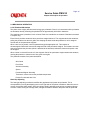
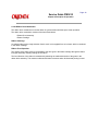
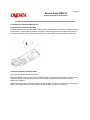
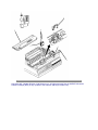
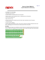
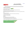
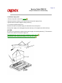
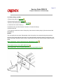
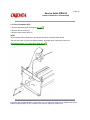
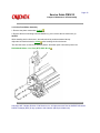
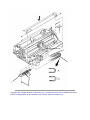
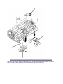
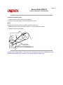
3.2.01 Printhead (with Preliminary Items)
WARNING:
The printhead will be HOT immediately after printing.
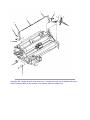
1. Open the printer access cover (1).
2. Remove the ribbon cartridge (2).
3. Set the head gap adjusting lever (3) to the range 9 position.
4. Lift and remove the ribbon guide (4) from the two posts.
5. Remove the two printhead mounting screws (5).
6. Disconnect the printhead (6) from the connector by lifting.
NOTES:
Installation
Push the printhead towards the platen (in the direction of Arrow A).
Perform the printhead gap adjustment. Refer to Section 3.3
P/N 50215701 Cover: Access RSPL B.2.02
P/N 50090301 Printhead: Assembly RSPL B.2.03
P/N 52105801 Ribbon Cartridge Consumable B.2.03
, B.2.12
P/N 56609701 Cord: AC (120V) RSPL B.2.03
P/N 56624101 Cord: AC (220V) (ML) Right Angle Option B.2.03
P/N 53062601 Guide: Ribbon Assembly RSPL B.2.05
Copyright 1997, Okidata, Division of OKI America, Inc. All rights reserved. See the OKIDATA Business
Partner Exchange (BPX) for any updates to this material. (http://bpx.okidata.com)
Page: 36
Service Guide PM3410
Chapter 3 Maintenance & Disassembly
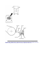
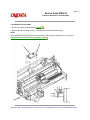
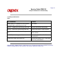
3.2.02 Ribbon Protector Assembly
1. Open the printer access cover.
2. Remove the ribbon cartridge.
3. Set the head gap adjusting lever to the range 9 position.
4. Lift and remove the ribbon guide from the two posts.
5. Remove the two mounting screws (1) and detach the ribbon protector (2) by lifting.
P/N 50316701 Screw: Ribbon Protector (Post) RSPL B.2.05
P/N 53062701 Protector: Ribbon Assembly RSPL B.2.05
Copyright 1997, Okidata, Division of OKI America, Inc. All rights reserved. See the OKIDATA Business
Partner Exchange (BPX) for any updates to this material. (http://bpx.okidata.com)
Page: 37
Service Guide PM3410
Chapter 3 Maintenance & Disassembly
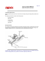
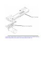
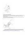
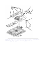
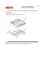
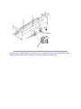
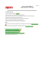
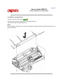
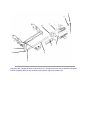
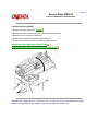
3.2.03 Upper Cover Assembly
1. Detach the platen knob (1).
2. Pull the release lever (2) toward the front of the printer.
3. Remove the two cover mounting screws (3), located at the rear of the printer.
4. Lift the sheet separator (4).
5. Open the bail arm (5).
6. Grasp the pull-up roller assembly (6), then lift and rotate it towards the back of the printer.
7. Close the bail arm.
8. Lower the sheet separator.
9. Lift the upper cover assembly (7) at the rear of printer. Rotate the assembly towards the front of the
printer, disengaging the cover from the four claws (8) at the front of the printer.
CAUTION:
When installing the upper cover assembly, move the bail arm lever towards the back of the printer and
move the release lever towards the front of the printer. Then, check that the paper bail moves properly.
P/N 50212431 Cover: Middle (PM3410) RSPL B.2.02
P/N 50215801 Cover: Rear (Assembly) RSPL B.2.02
P/N 50215901 Pull-Up Roller Assembly RSPL B.2.02
P/N 50215901 Pull-Up Roller Assembly RSPL B.2.03
P/N 53478601 Knob: Platen RSPL B.2.03
P/N 50910505 Spring: Cover Open RSPL B.2.04
Copyright 1997, Okidata, Division of OKI America, Inc. All rights reserved. See the OKIDATA Business
Partner Exchange (BPX) for any updates to this material. (http://bpx.okidata.com)
Page: 38
Service Guide PM3410
Chapter 3 Maintenance & Disassembly
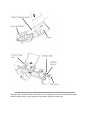
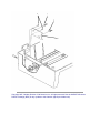
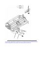
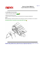
3.2.04 Operator Panel
1. Remove the upper cover assembly (3.2.03)
2. Disconnect the operator panel cable (1) from CN10 (2) on the control board.
3. Remove the two mounting screws (3).
4. Detach the operator panel assembly by moving it upward, and then pulling toward the front of the
printer, detaching the four claws.
5. Release the ten claws.
6. Detach the operator panel (4) from the operator panel holder (5).
P/N 53553401 Panel: Operator (PM3410) RSPL B.2.04
P/N 55061401 PCB: OPML Operation Panel RSPL B.2.04
P/N 56628402 Cable: Op Panel (PM3410) RSPL B.2.04
Copyright 1997, Okidata, Division of OKI America, Inc. All rights reserved. See the OKIDATA Business
Partner Exchange (BPX) for any updates to this material. (http://bpx.okidata.com)
Page: 39
Service Guide PM3410
Chapter 3 Maintenance & Disassembly
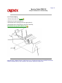
3.2.05 Interface Connector Board
NOTE:
To allow easier access to the mounting screw and cables, configure the interface connector board to use
the serial interface connector.
1. Remove the upper cover assembly (3.2.03).
2. Disconnect connectors CN101 (1), CN102 (2), and CN103 (3).
3. Remove the two mounting screws (4) and detach the interface connector board (5) by lifting.
NOTE:
After assembly, configure the interface connector board for the desired type of interface.
P/N 55061711 PCB: HKTY Interface Connector Assembly RSPL B.2.03
Copyright 1997, Okidata, Division of OKI America, Inc. All rights reserved. See the OKIDATA Business
Partner Exchange (BPX) for any updates to this material. (http://bpx.okidata.com)
Page: 40
Service Guide PM3410
Chapter 3 Maintenance & Disassembly
3.2.06 Main Logic (CBNP) Board
1. Remove the upper cover assembly. (3.2.03)
2. Remove the ribbon cartridge.
3. Release the lock of connector CN10 (1) and detach the operator panel cable (2).
4. Remove the five shield cover mounting screws (3).
5. While slightly lifting the shield cover (4), detach connectors CN11 (5) and CN12 (6) from the main logic
board.
6. Remove the shield cover.
7. Detach the connectors CN1, CN2, CN3, CN5, CN6, CN7, CN8, and CN9 (7).
8. Loosen the mounting screw (8).
9. Remove the main logic board (9).
CAUTION:
When assembling the printer, follow these instructions.
1. Do not allow cables to get caught under the main logic board.
2. Insert the main logic board into the groove in the base tray (10).
3. Fit the main logic board into the groove (11) in the shield cover, then secure the shield cover.
P/N 55061611 PCB: CPNB Main Logic (w/o ROM) RSPL B.2.03
P/N 55934601 IC: EEPROM NM93C06N-NW RSPL B.2.03
P/N 56212601 Switch: Interlock (Assy) RSPL B.2.04
Copyright 1997, Okidata, Division of OKI America, Inc. All rights reserved. See the OKIDATA Business
Partner Exchange (BPX) for any updates to this material. (http://bpx.okidata.com)
Page: 41
Service Guide PM3410
Chapter 3 Maintenance & Disassembly
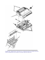
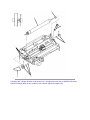
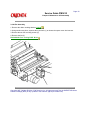
3.2.07 Printer Mechanism
1. Remove the main logic board (3.2.06).
2. Detach connectors CN102 (1) and CN103 (2) from the interface connector board (3).
3. Remove the three mounting screws (4) at the rear of the printer mechanism (5).
4. Remove the three mounting screws and brackets (6). There are two on the left side of the printer
mechanism and one on the right side.
CAUTION:
Do not grasp the ribbon cartridge bracket, paper chute, or the guide shaft of the sheet feeder assembly
when lifting the printer during the next step.
5. Grasp the printer mechanism near the line feed motor (Position A).
6. While holding at position A, also grasp the printer mechanism (Position B).
CAUTION:
DO NOT GRASP THE RIBBON CARTRIDGE BRACKET -- IT WILL BEND.
7. Lift and remove the printer mechanism.
NOTE:
When assembling the printer, do not allow cables to get caught under the printer mechanism.
P/N 56614101 Cord: Power Connection (9 Pin) RSPL B.2.03
P/N 56614801 Cord: Power Connection (13 Pin) RSPL B.2.03
P/N 56614901 Cable: I/F (Internal) [I/F-Main Brd 50 Pin] RSPL B.2.03
Copyright 1997, Okidata, Division of OKI America, Inc. All rights reserved. See the OKIDATA Business
Partner Exchange (BPX) for any updates to this material. (http://bpx.okidata.com)
Page: 42
Service Guide PM3410
Chapter 3 Maintenance & Disassembly
3.2.08 Power Supply Unit
1. Remove the printer mechanism (3.2.07).
2. Disconnect the two cables (1) from the left side of the power supply unit (2).
3. Remove the four power supply mounting screws (3).
4. To remove the power supply unit:
Rotate the left side of the power supply unit towards the front of the printer.
Lift the power supply unit to disengage the power switch (4), AC receptacle (5) and the tabs (6).
CAUTION:
Be careful not to damage the cables with the power supply unit mounting bracket (7). This bracket is
located at the left/rear of the power supply unit.
P/N 56406302 Power Supply Assembly (220/240 V) Option B.2.03
P/N 56411201 Power Supply Assembly (120 V) RSPL B.2.03
Copyright 1997, Okidata, Division of OKI America, Inc. All rights reserved. See the OKIDATA Business
Partner Exchange (BPX) for any updates to this material. (http://bpx.okidata.com)
Page: 43
Service Guide PM3410
Chapter 3 Maintenance & Disassembly
3.2.09 Printer Unit
1. Detach the DIN connector (1).
2. Lift the printer unit (2) from the bottom tractor feed unit (3).
Copyright 1997, Okidata, Division of OKI America, Inc. All rights reserved. See the OKIDATA Business
Partner Exchange (BPX) for any updates to this material. (http://bpx.okidata.com)
Page: 44
Service Guide PM3410
Chapter 3 Maintenance & Disassembly
3.2.10 BTFD PCB
1. Remove the printer unit (3.2.09).
2. Disconnect the connectors CN1 (1) and CN2 (2) on the BTFD PCB (3).
3. Remove the two mounting screws (4).
4. Remove the BTFD PCB.
P/N 55066101 PCB: BTFD (BTF) RSPL B.2.08
Copyright 1997, Okidata, Division of OKI America, Inc. All rights reserved. See the OKIDATA Business
Partner Exchange (BPX) for any updates to this material. (http://bpx.okidata.com)
Page: 45
Service Guide PM3410
Chapter 3 Maintenance & Disassembly
3.2.11 Tension Spring
1. Remove the printer unit (3.2.09).
2. Raise the front door assembly (1).
3. Detach the tension spring (2) from the upper plate (3).
4. Detach the tension spring from the front door assembly.
P/N 50922001 Spring: (BTF) RSPL B.2.08
Copyright 1997, Okidata, Division of OKI America, Inc. All rights reserved. See the OKIDATA Business
Partner Exchange (BPX) for any updates to this material. (http://bpx.okidata.com)
Page: 46
Service Guide PM3410
Chapter 3 Maintenance & Disassembly
3.2.12 Bottom Push Mechanism and Front Door Assembly
1. Remove the printer unit (3.2.09).
2. Remove the tension spring (3.2.11).
3. Detach connector CN1 (1) on the BTFD PCB (2).
4. Remove the four screws (3).
5. Remove the bottom push mechanism (4).
6. Remove the front door assembly (5).
P/N 53063701 Door: Front (Assembly) (BTF) RSPL B.2.08
Copyright 1997, Okidata, Division of OKI America, Inc. All rights reserved. See the OKIDATA Business
Partner Exchange (BPX) for any updates to this material. (http://bpx.okidata.com)
Page: 47
Service Guide PM3410
Chapter 3 Maintenance & Disassembly
3.2.13 Drive Pulley and Belt
1. Remove the printer unit (3.2.09).
2. Remove the tension spring (3.2.11).
3. Remove the bottom push mechanism (3.2.12).
4. Loosen the two motor screws (1).
5. Push the motor (2) in the direction of Arrow A, to loosen the belt (3).
6. Remove the belt.
7. Pry open the claws in the center of the pulley, then remove the drive pulley (4) from the tractor feed
drive shaft (5).
NOTES:
The drive pulley has two parts. Disassembly of the drive pulley is not required during this procedure.
Once the drive pulley has been removed, be sure that the tractor feed drive shaft is not removed. If you
remove the tractor feed drive shaft, the left or right tractors will lose the synchronization between the pin
feeds.
When assembling, perform the belt tension adjustment (3.3.02).
P/N 51226901 Pulley: Drive (BTF) RSPL B.2.08
P/N 51304501 Belt: Line Feed (BTF) Mini-Pitch [120 teeth] RSPL B.2.08
Copyright 1997, Okidata, Division of OKI America, Inc. All rights reserved. See the OKIDATA Business
Partner Exchange (BPX) for any updates to this material. (http://bpx.okidata.com)
Page: 48
Service Guide PM3410
Chapter 3 Maintenance & Disassembly
3.2.14 Tractor Assembly (BTF)
NOTE:
On each side frame, the tractor drive shaft passes through a plastic bushing. These bushings should
remain in the frame. However, if a bushing must be removed, press the bushings claw which can be
accessed from the inside of the side frame.
1. Remove the drive pulley (3.2.13).
2. Remove the tractor drive shaft (1) by sliding it to the right.
3. Rotate the tops of both the left (2) and right (3) tractor assemblies and the sheet guide (not shown) in
the direction of Arrow A.
4. Lift the left side of the drive roller (4) and remove the drive roller, tractor assemblies, and sheet guide.
NOTES:
The sheet guide may be removed without disassembling the drive shaft.
When installing the tractor assemblies, take the following precautions:
Make sure that the tractors are synchronized by aligning the synchronization marks (5).
The left tractor assembly must be positioned to the left of the metal tab.
P/N 50057401 Left Tractor Assembly RSPL B.2.08
P/N 50057501 Right Tractor Assembly RSPL B.2.08
P/N 51002201 Guide: Sheet (BTF) RSPL B.2.08
P/N 53340401 Roller: Drive (BTF) RSPL B.2.08
Copyright 1997, Okidata, Division of OKI America, Inc. All rights reserved. See the OKIDATA Business
Partner Exchange (BPX) for any updates to this material. (http://bpx.okidata.com)
Page: 49
Service Guide PM3410
Chapter 3 Maintenance & Disassembly
3.2.15 Line Feed Motor (BTF)
1. Remove the bottom push mechanism (3.2.12).
2. Remove the two screws (1).
3. Remove the line feed motor (2).
NOTE:
When installing the line feed motor, the harness should be oriented towards the top.
This line feed motor is used in two different places: the bottom push unit and the printer unit.
P/N 56509401 Motor: Line Feed (BTF) RSPL B.2.08
Copyright 1997, Okidata, Division of OKI America, Inc. All rights reserved. See the OKIDATA Business
Partner Exchange (BPX) for any updates to this material. (http://bpx.okidata.com)
Page: 50
Service Guide PM3410
Chapter 3 Maintenance & Disassembly
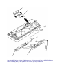
3.2.16 Platen Assembly
1. Remove the printer mechanism (3.2.07).
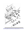
2. Loosen the three 7 mm line feed motor mounting bolts (1).
3. Move the line feed motor (2) closer to the platen (3) and detach the line feed drive belt (4).
4. Remove the E-ring, washer, spring and idle gear (5).
5. Remove the screw and detach the gear pulley, washer and bushing (6).
6. Remove the screw and detach the gear and bushing (7).
7. Push in the platen lever (8), lift the bail and remove the platen.
NOTE:
Perform the line feed belt tension adjustment after replacing the line feed drive belt. Refer to Section 3.3
Perform the printhead gap adjustment after installing the platen. Refer to Section 3.3
P/N 50054101 Platen: (Assembly) RSPL B.2.06
P/N 51214501 Gear: Platen "A" RSPL B.2.06
P/N 51226801 Pulley: Platen RSPL B.2.06
P/N 51304401 Belt: Mini Pitch (Line Feed) RSPL B.2.06
OLD P/N 50910305 Spring: Idle Gear
Copyright 1997, Okidata, Division of OKI America, Inc. All rights reserved. See the OKIDATA Business
Partner Exchange (BPX) for any updates to this material. (http://bpx.okidata.com)
Page: 51
Service Guide PM3410
Chapter 3 Maintenance & Disassembly
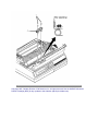
3.2.17 Paper Pressure Guide
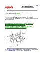
1. Remove the platen assembly (3.2.16)
2. Remove the two paper chute springs (1) located on each side of the paper pressure guide (2).
3. Remove the screw (3), located on the left side frame of the printer mechanism, directly under the upper
tractor shaft.
4. Remove the release lever detent spring (4) located on the right side frame of the printer mechanism.
5. Separate the claws and remove the release lever (5).
6. Remove the paper pressure bar (6) by sliding it to the right.
7. Using needle-nose pliers, squeeze the nylon latch (7) to release the paper out sensor wire harness (8).
8. Detach the cable from CN1 of the sensor board (9).
9. Lift the paper pressure guide and remove it.
P/N 50907502 Spring: (Paper Chute) RSPL B.2.06
P/N 50910201 Spring: Detent (Release Lever) RSPL B.2.06
P/N 53478706 Lever: Release RSPL B.2.06
P/N 53478801 Block: Release Lever Guide RSPL B.2.06
P/N 56625001 Cable: Cut Sheet Sensor Assembly RSPL B.2.06
Copyright 1997, Okidata, Division of OKI America, Inc. All rights reserved. See the OKIDATA Business
Partner Exchange (BPX) for any updates to this material. (http://bpx.okidata.com)
Page: 52
Service Guide PM3410
Chapter 3 Maintenance & Disassembly
3.2.18 Line Feed Motor Assembly
1. Remove the printer mechanism (3.2.07)
2. Remove the three mounting bolts and washers (1), then remove the line feed motor (2).
NOTES:
When installing the line feed motor, the cable should be positioned toward the top.
Adjust the line feed belt tension (3.3.02)
after installing the line feed motor.
This line feed motor is used in two different places: the bottom push unit and the printer unit.
P/N 56509401 Motor: Line Feed (BTF) RSPL B.2.06
Copyright 1997, Okidata, Division of OKI America, Inc. All rights reserved. See the OKIDATA Business
Partner Exchange (BPX) for any updates to this material. (http://bpx.okidata.com)
Page: 53
Service Guide PM3410
Chapter 3 Maintenance & Disassembly
3.2.19 Ribbon Cartridge Bracket
1. Remove the printer mechanism (3.2.07)
2. Remove the two ribbon cartridge bracket mounting screws (1).
3. Remove the ribbon cartridge bracket (2).
NOTE:
When assembling, the tabs (3) on each side of the ribbon cartridge bracket must slide into the slots on the
printer mechanism.
Copyright 1997, Okidata, Division of OKI America, Inc. All rights reserved. See the OKIDATA Business
Partner Exchange (BPX) for any updates to this material. (http://bpx.okidata.com)
Page: 54
Service Guide PM3410
Chapter 3 Maintenance & Disassembly
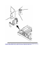
3.2.20 Fan Assembly
1. Remove the ribbon cartridge bracket (3.2.19).
2. Using needle-nose pliers, squeeze the nylon latch (1) to release the space motor wire harness.
3. Remove the two fan mounting screws (2).
4. Remove the fan (3).
P/N 56509501 Fan: Cooling RSPL B.2.03
Copyright 1997, Okidata, Division of OKI America, Inc. All rights reserved. See the OKIDATA Business
Partner Exchange (BPX) for any updates to this material. (http://bpx.okidata.com)
Page: 55
Service Guide PM3410
Chapter 3 Maintenance & Disassembly
3.2.21 Head Cable Assembly
1. Detach the printhead (3.2.01)
2. Remove the ribbon cartridge bracket (3.2.19).
3. Loosen the two mounting screws (1), detach the tabs from the frame and remove the cable holder (2).
The tabs must be accessed from the bottom of the printer mechanism.
4. Remove the mounting screw (3) and detach the connector clamp (4).
5. Detach the head cable connector (5) from the carriage frame (6).
6. Slide the carriage to the left side frame. While lifting the front end of the printer mechanism, remove the
head cable assembly (7) by pulling downward.
P/N 56624901 Cable: Head Assembly RSPL B.2.05
Copyright 1997, Okidata, Division of OKI America, Inc. All rights reserved. See the OKIDATA Business
Partner Exchange (BPX) for any updates to this material. (http://bpx.okidata.com)
Page: 56
Service Guide PM3410
Chapter 3 Maintenance & Disassembly
3.2.22 Carriage and Carriage Shaft
1. Remove the head cable assembly (3.2.21)
2. Loosen the slider mounting screw (1) and push it towards the back of the printer.
3. Remove the belt clamp mounting screw (2) and detach the belt clamp (3).
4. Loosen the screw (4) and detach the left printhead gap adjusting collar (5).
NOTE:
The protrusions on the collar face the outside of the printer.
5. Remove the screw and detach the blue printhead gap adjusting lever (not shown).
6. Loosen the screw (6) and detach the right printhead gap adjusting collar (7).
7. Pull the two rubber carriage bumpers (8) from the carriage shaft (9).
8. Slide the carriage shaft to the right and remove the shaft and the carriage assembly (10).
NOTES:
Installation
Be sure that the larger extension at the end of the carriage shaft is positioned to the right.
Perform the printhead gap adjustment after installing this assembly. Refer to Section 3.3
P/N 53340501 Carriage: (Assembly) RSPL B.2.05
P/N 50706701 Collar: Eccentric (with Screw) RSPL B.2.06
P/N 51112101 Shaft: Carriage RSPL B.2.06
P/N 53063801 Bracket: Printhead Gap Indicator RSPL B.2.06
P/N 53478401 Lever: Adjust RSPL B.2.06
Copyright 1997, Okidata, Division of OKI America, Inc. All rights reserved. See the OKIDATA Business
Partner Exchange (BPX) for any updates to this material. (http://bpx.okidata.com)
Page: 57
Service Guide PM3410
Chapter 3 Maintenance & Disassembly
3.2.23 Ribbon Feed Assembly
1. Remove the ribbon cartridge bracket (3.2.19).
2. Remove the two mounting screws (1) and detach the ribbon feed assembly (2).
NOTE:
When assembling, install the ribbon drive assembly so that the gear backlash (3) is at a minimum.
P/N 50054301 Assembly: Ribbon Feed RSPL B.2.06
Copyright 1997, Okidata, Division of OKI America, Inc. All rights reserved. See the OKIDATA Business
Partner Exchange (BPX) for any updates to this material. (http://bpx.okidata.com)
Page: 58
Service Guide PM3410
Chapter 3 Maintenance & Disassembly
3.2.24 Space Motor Assembly
1. Remove the ribbon feed assembly (3.2.23).
2. Loosen the two belt pulley bracket mounting screws (1). While pushing the belt pulley bracket to the left
(A), temporarily tighten the two screws. This will ease the tension on the space belt.
3. Remove the three space motor mounting screws (2).
4. Remove the space motor (3) by pulling toward the front of the printer.
P/N 56506204 Motor: Space RSPL B.2.06
Copyright 1997, Okidata, Division of OKI America, Inc. All rights reserved. See the OKIDATA Business
Partner Exchange (BPX) for any updates to this material. (http://bpx.okidata.com)
Page: 59
Service Guide PM3410
Chapter 3 Maintenance & Disassembly
3.2.25 Space Belt
1. Remove the printhead (3.2.01)
2. Remove the space motor assembly (3.2.24)
3. Remove the mounting screw and detach the connector clamp (1). Detach the head cable assembly (2)
from the carriage.
4. Remove the mounting screw (3) and detach the belt clamp (4).
5. Remove the belt pulley (5) from the bracket (6) and detach the space belt (7).
P/N 50702301 Belt Clamp B.2.05
P/N 51303101 Belt: Mini Pitch (Spacing) RSPL B.2.05
Copyright 1997, Okidata, Division of OKI America, Inc. All rights reserved. See the OKIDATA Business
Partner Exchange (BPX) for any updates to this material. (http://bpx.okidata.com)
Page: 60
Service Guide PM3410
Chapter 3 Maintenance & Disassembly
3.2.26 Sensor Board (LPRW)
1. Remove the printer mechanism (3.2.07).
2. Disconnect connectors CN1 and CN2 (1) from the sensor board (2).
3. Raise the front of the printer mechanism.
4. Remove the three sensor board mounting screws (3).
5. Disconnect connector CN3 (4) and detach the sensor board.
P/N 55061501 PCB: LPRW Sensor RSPL B.2.06
P/N 56616804 Cable: Sensor Board Connection RSPL B.2.06
Copyright 1997, Okidata, Division of OKI America, Inc. All rights reserved. See the OKIDATA Business
Partner Exchange (BPX) for any updates to this material. (http://bpx.okidata.com)
Page: 61
Service Guide PM3410
Chapter 3 Maintenance & Disassembly
3.2.27 Bail Motor/Gear Assembly
1. Remove the printer mechanism (3.2.07).
2. Disconnect connector CN2 (1).
3. Remove the two mounting screws (2) and detach the bail motor/gear assembly (3).
NOTE:
When assembling, install the bail/ribbon motor assembly so that the gear backlash is at a minimum.
P/N 56506301 Motor: Step (Bail Arm) Assembly RSPL B.2.06
Copyright 1997, Okidata, Division of OKI America, Inc. All rights reserved. See the OKIDATA Business
Partner Exchange (BPX) for any updates to this material. (http://bpx.okidata.com)
Page: 62
Service Guide PM3410
Chapter 3 Maintenance & Disassembly
3.2.28 Paper Bail Assembly
1. Remove the printer mechanism (3.2.07).
2. Remove the bail motor / ribbon gear assembly (3.2.27).
3. Detach the paper bail springs (1).
NOTE:
The right and left bail arm springs are different; be careful to install them properly. 4. Remove the idler
gear (2).
5. Detach the E snap ring and remove the bail open cam (3).
6. Detach the E snap ring (4) and remove the left bail arm (5) from the paper bail bar (6) by pulling toward
the left.
7. Remove the right bail arm (7) by pulling toward the right while expanding the clamps (8).
8. Detach the right bail arm from the paper bail bar.
P/N 50054401 Assembly: Indicator Shaft RSPL B.2.07
P/N 50910701 Spring: Bail Arm (Left) RSPL B.2.07
P/N 50910801 Spring: Bail Arm (Right) RSPL B.2.07
P/N 51210201 Gear: Idle (Bail Arm) RSPL B.2.07
P/N 51214701 Cam: Bail Open RSPL B.2.07
P/N 53478501 Bail Arm (Left) RSPL B.2.07
P/N 53478502 Bail Arm (Right) RSPL B.2.07
Copyright 1997, Okidata, Division of OKI America, Inc. All rights reserved. See the OKIDATA Business
Partner Exchange (BPX) for any updates to this material. (http://bpx.okidata.com)
Page: 63
Service Guide PM3410
Chapter 3 Maintenance & Disassembly
3.2.29 Rear Feed Tractor Assembly
1. Remove the printer mechanism (3.2.07).
2. Remove the lower center guide (1).
3. Separate the claws (2) and remove the two drive gears from the right side of the printer mechanism (3A
- Drive Gear A and 3B - Drive Gear B).
4. Using a needle nose pliers, remove the nylon cable clamp (4).
5. Slide the upper drive shaft (5) to the left and remove it.
6. Slide the lower drive shaft (6) to the left and remove it.
7. Remove the upper center guide (7), being careful not to lose the friction ring (8).
8. Lift and remove the push tractor assemblies (9) and locking shaft (10).
NOTES:
To remove the tractors , raise the lock levers and slide the tractors off.
When installing the push tractor assembly, take the following precautions: 9. First, install the friction ring in
the upper center guide. If the upper center guide moves easily along the locking shaft, you must rotate the
friction ring 45 degrees, using a standard screwdriver (11).
10. Check the installation; if the guide moves with difficulty, it is properly installed.
11. Make sure that the tractors are synchronized by aligning the synchronization marks in the same
direction.
12. Make sure that the guide holes (12) in the tractor drive gears face the same direction.
13. The groove of the upper center guide must be positioned behind the paper pressure guide (13).
14. The left tractor assembly must be positioned between the two guide tabs (14).
P/N 50054501 Tractor: Push (Left) Assembly RSPL B.2.07
P/N 50054601 Tractor: Push (Right) Assembly RSPL B.2.07
P/N 51002301 Friction: Piece RSPL B.2.07
P/N 51002401 Guide: Center - Upper RSPL B.2.07
P/N 51002501 Guide: Center Lower A RSPL B.2.07
P/N 51002601 Guide: Center Lower B RSPL B.2.07
Copyright 1997, Okidata, Division of OKI America, Inc. All rights reserved. See the OKIDATA Business
Partner Exchange (BPX) for any updates to this material. (http://bpx.okidata.com)
Page: 64
Service Guide PM3410
Chapter 3 Maintenance & Disassembly
3.2.30 Printhead Gap/Release Lever Microswitches
1. Remove the printer mechanism (3.2.07).
2. Remove the mounting screw to remove the release lever microswitch (1).
3. Push down on the mounting tab and detach the upper printhead gap microswitch (2).
4. Push down on the mounting tab and detach the lower printhead gap microswitch (3).
5. Using a needle nose pliers, detach the nylon cable clamp (4) and remove the harness and switches
from the printer mechanism.
NOTES:
The harness connector must be detached from the main logic board.
Refer to the Microswitch 2 Modification procedure in Section 3.3 - Adjustments.
P/N 56209901 Switch: Micro (Adj & Rel Lever) RSPL B.2.07
P/N 56624801 Cable: Micro Switch Assembly (Adj & Rel Lever) RSPL B.2.07
P/N 56614301 Cable: Micro Switch (Cover Open) RSPL B.2.04
Copyright 1997, Okidata, Division of OKI America, Inc. All rights reserved. See the OKIDATA Business
Partner Exchange (BPX) for any updates to this material. (http://bpx.okidata.com)
Page: 65
Service Guide PM3410
Chapter 3 Maintenance & Disassembly
3.2.31 Release Lever / Gear Assemblies
6. Remove the printer mechanism (3.2.07).
NOTE:
Before performing the next step, place the release lever toward the front of the printer. This will remove
tension from the detent spring.
7. Detach the E-Ring, washer and spring, then remove the idle gear (1).
8. Remove the (Release Lever) detent spring (2).
9. Pry open the center claws and slide the release lever (3) from the printer mechanism.
10. Pry open the center claws then remove drive gear A (large gear) (4).
11. Pry open the center claws then remove drive gear B (small gear) (5).
P/N 50910305 Spring: Idle Gear RSPL B.2.07
P/N 51214201 Gear: Drive A RSPL B.2.07
P/N 51214301 Gear: Drive B RSPL B.2.07
P/N 51214401 Gear: Idle (Release Lever) RSPL B.2.07
P/N 53478706 Lever: Release RSPL B.2.06
P/N 50910201 Spring: Detent (Release Lever) RSPL B.2.06
Copyright 1997, Okidata, Division of OKI America, Inc. All rights reserved. See the OKIDATA Business
Partner Exchange (BPX) for any updates to this material. (http://bpx.okidata.com)
Page: 66
Service Guide PM3410
Chapter 3 Maintenance & Disassembly
3.3 PRINTER ADJUSTMENTS
3.3.01 General Information
This section contains the procedures for performing adjustments on the printer. These procedures may be
required when replacing either consumables or parts. The disassembly / assembly procedures list the
required adjustment and refer you to this section. Failure to perform these procedures may result in
unnecessary service calls.
Copyright 1997, Okidata, Division of OKI America, Inc. All rights reserved. See the OKIDATA Business
Partner Exchange (BPX) for any updates to this material. (http://bpx.okidata.com)
Page: 67
Service Guide PM3410
Chapter 3 Maintenance & Disassembly
3.3.02 Printhead Gap
NOTES:
The information in this section is also covered in Technical Service Bulletin 1603. A Pacemark 3410
Replacement Printhead Kit includes the items listed below.
Technical Service Bulletin 1603
Read Me First Card
Head Gap Lever Adjustment Sticker
90 Day Warranty Extension Card
General Information
Before performing this adjustment, always verify that the printhead is properly installed.
The printhead gap adjustment should be performed when the following occur.
Print quality is darker on one side of the document.
Parts / Assemblies are replaced.
Printhead Assembly (3.2.01)
Platen Assembly (3.2.16)
Carriage Shaft (3.2.22)
The printhead gap should measure .014 +/- .002 inches (0.35 +/- 0.05 millimeters).
This adjustment has four phases.
1. Setup Phase (Steps 1 - 6)
The cover is removed and the printhead is placed at a known reference point.
2. Printhead Gap Modification Phase (Steps 7 - 9)
The distance between the printhead and the platen at the left (line feed motor) side of the platen is
modified by rotating the left eccentric collar. Rotating the eccentric collar varies the position of the carriage
shaft relative to the platen.
3. Parallel Adjustment Phase (Steps 10 - 12)
The right eccentric collar is rotated to ensure that the printhead moves parallel to the platen (at the correct
gap setting).
4. Check Phase (Steps 13 - 16)
This phase verifies that the Parallel Adjustment Phase did not affect the Printhead Gap Modification
Phase.
Procedure
NOTE:
The printhead gap must measure .014 +/- .002 inches (0.35 +/- 0.05 millimeters).
Setup Phase (Steps 1 - 6)
1. Remove the ribbon cartridge and ribbon guide (3.2.01).
2. Remove the ribbon protector (3.2.02).
3. Remove the upper cover (3.2.03).
4. Set the printhead gap lever to position 1.
5. Set the release lever to the CUT SHEET ("OPEN") position.
6. Loosen the left and right eccentric collar mounting screws.
Printhead Gap Modification Phase (Steps 7 - 9)
7. Move the printhead to the left side of the platen.
8. Rotate the left eccentric collar until the correct gap is obtained.
9. Move the printhead to the right side of the platen.
Parallel Adjustment Phase (Steps 10 - 12)
10. Rotate the right eccentric collar until the correct gap is obtained.
11. Move the printhead to the left side of the platen.
12. Recheck the gap, rotating the left eccentric collar as necessary.
Check Phase (Steps 13 - 16)
13. Move the printhead to the right side of the platen.
14. Check the gap, rotating the right eccentric collar as necessary.
15. Repeat Steps 11 - 14 until the correct gap is obtained at each side of the platen.
16. Move the printhead to the center of the platen and check the gap.
17. When the correct gap has been attained, tighten the left and right eccentric collar mounting screws.
18. Install the upper cover, the ribbon protector, ribbon guide and the ribbon cartridge.
NOTE:
When installing the printhead, push it towards the platen. This ensures a correct fit between the printhead
and stopper. Then, tighten the printhead screws.
Diagram
Microswitch 2 Modification
NOTES:
The information in this section is also covered in Technical Service Bulletin 1603.
A Pacemark 3410 Replacement Printhead Kit includes the items listed below.
TSB 1603
Read Me First Card
Head Gap Lever Adjustment Sticker
90 Day Warranty Extension Card
General Information
Modifying Microswitch 2 will reduce drive time and increase printhead life.
Perform this modification when a replacement printhead is installed.
Procedure
1. Remove the upper cover. (3.2.03)
2. Locate the blue head gap lever.
3. Set the blue head gap lever to Position 1.
4. Locate the two microswitches on the right side (platen knob) of the printer. The microswitch below the
head gap lever is Microswitch 2.
5. Make a paper clip into a hook.
6. Insert the paper clip hook into the small hole on the microswitch arm.
CAUTION:
The paper clip hook will keep the arm from falling into the printer during the next step.
7. Hold the paper clip and carefully cut the arm of Microswitch 2 at its base.
8. Discard the cut arm.
Verification
To verify that Microswitch 2 has been disabled, follow this procedure.
1. Set the head gap lever to position 5 or above.
2. Attach an ohmmeter to pins 5 and 6 of connector CN9 on the main control board.
3. Verify that the switch is closed.
4. Set the head gap lever to the proper setting for the paper (thickness) being used.
5. Replace the upper cover.
6. Place the Head Gap Lever Adjustment Sticker on the tear bar of the access cover.
7. Fill out the Customer Warranty Extension Card (if applicable).
Read Me First
The Read Me First Sheet in the Pacemark 3410 Replacement Printhead Kit reads as follows.
When changing paper paths or paper type, be sure to adjust the printhead gap lever. This blue lever is
located on the right hand side of the printer. Failure to correctly adjust this lever could result in damage to
the printhead.
Key Combination
Function
PRINT QUALITY + CHARACTER PITCH (Either
during ON-LINE or hold during power ON)
Menu Mode
SELECT + FORM FEED (Hold during power ON)
Activates Hexadecimal Dump Mode
SELECT + LINE FEED (Hold during power ON)
Resets Printer Menu to factory defaults
SELECT + TOP OF FORM (Hold during power
ON)
Resets Printer Menu and Top of Form to factory
defaults
LINE FEED (Hold during power ON)
Activate Font Test To end Font Test press
SELECT
FORM FEED (Hold during power ON)
Activate Rolling ASCII Test To end Rolling ASCII
Test press SELECT
90 Day On-Site Warranty Extension
The 90 Day On-Site Warranty Extension in the Pacemark 3410 Replacement Printhead Kit reads as
follows.
This document entitles the owner an extension of the initial 90 day on-site warranty.
The extension will cover any printhead repair performed within the first 90 days after the date of purchase
and extend the warranty for 90 days from the date of the printhead repair.
Any Authorized Pacemark 3410 Okidata Repair Center will honor this extension when properly dated and
signed by a certified repair technician. Please retain this for your records.
Date of Purchase: ______________ Printer Serial Number ________________________
Date of Printhead Repair ___________ 90 Day Extension Expiration Date _____________
Authorized Okidata Repair Center ____________________ Dealer Number ____________
Technician Name ____________________ Technician Signature ____________________
Customer's Name and Address _____________________________________________
______________________________________________
______________________________________________
ODA P/N 58084801
Copyright 1997, Okidata, Division of OKI America, Inc. All rights reserved. See the OKIDATA Business
Partner Exchange (BPX) for any updates to this material. (http://bpx.okidata.com)
Page: 68
Service Guide PM3410
Chapter 3 Maintenance & Disassembly
3.3.02 Line Feed Belt Tension
1. Loosen the three line feed motor mounting bolts (1).
2. Using a tension gauge, apply .5 pounds of pressure at Point A.
NOTE:
Rotate the platen pulley at least once before making the adjustment
3. Adjust the line feed motor (2) position to obtain a 1 /16 inch deflection as shown.
4. Tighten the three mounting bolts.
Copyright 1997, Okidata, Division of OKI America, Inc. All rights reserved. See the OKIDATA Business
Partner Exchange (BPX) for any updates to this material. (http://bpx.okidata.com)
Page: 69
Service Guide PM3410
Chapter 3 Maintenance & Disassembly
3.3.03 Key Combinations
Table
Key Combination
Function
PRINT QUALITY + CHARACTER PITCH (Either
during ON-LINE or hold during power ON)
Menu Mode
SELECT + FORM FEED (Hold during power ON)
Activates Hexadecimal Dump Mode
SELECT + LINE FEED (Hold during power ON)
Resets Printer Menu to factory defaults
SELECT + TOP OF FORM (Hold during power
ON)
Resets Printer Menu and Top of Form to
factory defaults
LINE FEED (Hold during power ON)
Activate Font Test To end Font Test
press SELECT
FORM FEED (Hold during power ON)
Activate Rolling ASCII Test To end Rolling
ASCII Test press SELECT
Copyright 1997, Okidata, Division of OKI America, Inc. All rights reserved. See the OKIDATA Business
Partner Exchange (BPX) for any updates to this material. (http://bpx.okidata.com)
Page: 70
Service Guide PM3410
Chapter 3 Maintenance & Disassembly
3.3.04 Menu Operation
General Description
The Menu is used to customize the printers settings and features.
The Menu is made up of a number of groups.
Each group has a list of items.
Each item has several settings.
Menu Mode
To enter Menu Mode, follow this procedure.
1. Verify that continuous feed paper is installed.
2. Verify that the ribbon is correctly installed.
3. Verify that the width of the installed paper matches the paper width menu setting.
4. Press PRINT QUALITY and CHARACTER PITCH at the same time to place the printer in Menu Mode.
When in Menu Mode, the functions printed below the operator panels switches are active.
5. Press GROUP until the desired Group prints.
6. Press ITEM until the desired Item prints.
7. Press SET until the desired setting prints.
8. Press EXIT to save the change and exit Menu Mode.
Printing the Menu
Printing the Menu provides a reference of current settings.
This will help you move through the menu.
Okidata STRONGLY RECOMMENDS printing the Menu before resetting the Menu to factory defaults.
To print the Menu, follow this procedure.
1. Verify that continuous feed paper is installed.
2. Verify that the ribbon is correctly installed.
3. Verify that the width of the installed paper matches the paper width menu setting.
4. Power ON the printer.
5. Press and hold PRINT QUALITY and CHARACTER PITCH at the same time to place the printer in
Menu Mode.
When in Menu Mode, the functions printed below the operator panels switches are active.
6. Press PRINT.
7. The Menu will print.
8. Press EXIT to exit Menu Mode.
Reset Menu to Factory Defaults
To reset the Menu to Factory Defaults, follow this procedure.
1. Before resetting the Menu, Okidata STRONGLY RECOMMENDS printing the Menu.
Printing the Menu provides a reference of customized settings.
When the Menu is reset, all customized setting are LOST.
2. Power OFF the printer.
3. Press and hold SELECT and LINE FEED while powering ON the printer.
Reset Menu and Top of Form to Factory Defaults
To reset the Menu and the Top of Form to Factory Defaults, follow this procedure.
1. Before resetting the Menu, Okidata STRONGLY RECOMMENDS printing the Menu.
Printing the Menu provides a reference of customized settings.
When the Menu is reset, all customized setting are LOST.
2. Power OFF the printer.
3. Press and hold SELECT and TOP OF FORM while powering ON the printer.
Limited Operation
In the Printer Menu, the fifth item in the Set-Up Group is Operator Panel Function.
The settings for this Item are Full Operation and Limited Operation. The factory default is Full Operation.
A system manager may use this feature to maintain proper print settings if the printer is part of a
customized system or if the printer is used by different operators.
When the Printer Menu is set to Limited Operation, the TOP OF FORM, MICRO FEED UP/DOWN, PRINT
QUALITY, and PITCH switches of the operator panel DO NOT work. Menu Mode CANNOT be accessed.
To change from LIMITED OPERATION to FULL OPERATION, follow this procedure.
1. Verify that continuous feed paper is installed.
2. Verify that the ribbon is correctly installed.
3. Verify that the width of the installed paper matches the paper width menu setting.
4. Power OFF the printer.
5. Press and hold PRINT QUALITY and CHARACTER PITCH while powering ON the printer to place the
printer in Menu Mode.
When in Menu Mode, the functions printed below the operator panels switches are active.
6. Press GROUP until Set-Up prints.
7. Press ITEM until Operator Panel Function prints.
8. Press SET until FULL OPERATION prints.
9. Press EXIT to exit Menu Mode.
Copyright 1997, Okidata, Division of OKI America, Inc. All rights reserved. See the OKIDATA Business
Partner Exchange (BPX) for any updates to this material. (http://bpx.okidata.com)
Page: 71
Service Guide PM3410
Chapter 3 Maintenance & Disassembly
Menu Settings
Factory default settings are printed in Bold Italic.
Except as indicated, the menu for the Epson/IBM model is the same as the menu for the ML/Pacemark
model.
Group
Item
Setting
Notes
Printer Mode
Emulation Mode
(Epson/IBM)
Epson FX IBM PPR
Refer to the Printer
Handbook
Emulation Mode
(ML/Pacemark)
Microline Pacemark
2410
Refer to the Printer
Handbook
Print Mode
Utility NLQ Courier
NLQ Gothic HSD
Pitch (Epson / IBM)
10 12 15 17.1 20
cpi
Pitch (ML /
Pacemark)
10 12 15 17.1 20
cpi
Style
Normal Italics
Size
Single Double
Double is double width
and height
Character Set
Set I Set II
These are standard
IBM character sets.
Language Set
American
French German
British Danish I
Swedish Italian
Spanish I Japanese
Norwegian Danish II
Spanish II Latin
American French
Canadian Dutch
Publisher
Font
Symbol Sets
Proportional spacing is
a separate menu item
in the ML/Pacemark
menu.
These sets
contain special
characters used
in foreign
languages. The
Publisher set
includes special
printing symbols.
Zero Character
Slashed Unslashed
Use slashed zero to
distinguish from the
capital letter O.
Code Page
USA Canada French
Multilingual Portugal
Norway
Matches the character
set to the computer
display character set.
Refer to a DOS
manual.
The next three groups set parameters for each of the paper paths independently.
When changing from one path to another the parameters also automatically change.
Group
Item
Setting
Notes
Rear Feed
Line Spacing
6 8 LPI
Sets the distance
between line in lines
per inch.
Form Tear Off
OFF 500 mS 1 sec
2 sec
Activate the form tear
off feature by selecting
a time for the printer to
wait after data before
advancing the page to
tear-off. If the software
pauses during printing
print registration may
be disrupted. Select a
longer time or
deactivate this feature.
Refer to the Printer
Handbook.
Skip Over Perforation
No Yes
When set to YES the
printer advances the
paper 1 inch (when
reaching the bottom of
the page) to the next
top of form. Use ONLY
for unformatted listings
or programs that don't
format the page.
Page Width
13.6" 8"
Page Length
11" 11 2/3" 12" 14"
17" 3" 3.5" 4" 5.5"
6" 7" 8" 8.5"
The 8" setting emulates
a narrow carriage
printer. If 8.5" paper is
always used choose
this setting to prevent
printing on the platen.
Group
Item
Setting
Notes
Bottom Feed
Line Spacing
6 8 LPI
Sets the distance
between line in lines
per inch.
Form Tear Off
OFF 500 mS 1 sec
2 sec
Activate the form tear
off feature by selecting
a time for the printer to
wait after data before
advancing the page to
tear-off. If the software
pauses during printing
print registration may
be disrupted. Select a
longer time or
deactivate this feature.
Refer to the Printer
Handbook.
Skip Over Perforation
No Yes
When set to YES the
printer advances the
paper 1 inch (when
reaching the bottom of
the page) to the next
top of form. Use ONLY
for unformatted listings
or programs that don't
format the page.
Page Width
13.6" 8"
The 8" setting emulates
a narrow carriage
printer. If 8.5" paper is
always used choose
this setting to prevent
printing on the platen.
Page Length
11" 11 2/3" 12" 14"
17" 3" 3.5" 4" 5.5"
6" 7" 8" 8.5"
Group
Item
Setting
Notes
Top Feed
Line Spacing
6 8 LPI
Sets the distance
between line in lines
per inch.
Skip Over Perforation
No Yes
When set to YES the
printer advances the
paper 1 inch (when
reaching the bottom of
the page) to the next
top of form. Use ONLY
for unformatted listings
or programs that don't
format the page.
Page Width
13.6" 8"
The 8" setting emulates
a narrow carriage
printer. If 8.5" paper is
always used choose
this setting to prevent
printing on the platen.
Page Length
11" 11 2/3" 12" 14"
17" 3" 3.5" 4" 5.5"
6" 7" 8" 8.5"
Group
Item
Setting
Notes
Set-Up
Graphics
Bi-directional
Unidirectional
Bi-directional prints
from left to right then
right to left. It is faster
but may cause
registration problems.
Unidirectional prints
from left to right ONLY.
It is more precise but
slower.
Max. Receive Buffer
1 Line 4K 16K 28K
Specifies the amount of
the printer's buffer used
to store data.
Paper Out Override
No Yes
A sensor stops printing
about 1 inch from the
bottom of a single
page. Changing this
setting to YES allows
printing to occur closer
to the bottom edge of
the paper.
Print Registration
0.25 mm Right
0.20 mm Right
0.15 mm Right
0.10 mm Right
0.05 mm Right
0.00 mm
0.05 mm Left
0.10 mm Left
0.15 mm Left
0.20 mm Left
0.25 mm Left
Adjusts the vertical
registration in graphics.
The best setting may
vary from one software
package to another.
Group
Item
Setting
Notes
Set-Up (continued
Operator Panel
Function
Full Operation Limited
Operation
Changing this setting to
Limited Operation
deactivates the menu
mode and these control
panel buttons: TOP
OF FORM MICRO
FEED UP/DOWN
PRINT QUALITY and
PITCH. This is used in
situations where
several people are
using the printer. To
restore to full operation
power OFF the printer.
Press and hold PRINT
QUALITY and PITCH
while powering ON the
printer. The printer will
be in Menu Mode.
Change this setting to
FULL OPERATION.
Reset Inhibit
No Yes
Changing this to Yes
prevents a reset signal
from the computer from
resetting the printer to
its defaults.
Print Suppress
Effective
Yes No
Determines whether
the DC3 code causes
the printer to ignore
data until a DC1 code
is received.
Auto LF
No Yes
Auto CR (IBM only)
No Yes
CSF Bin Select
Bin 1 Bin 2
Only available when the
dual bin cut sheet
feeder (CSF 3002) is
installed. Determines
which bin is active.
SI Select Pitch (10 cpi IBM ONLY)
17.1 15 cpi
Sets the pitch of
condensed mode from
10 cpi using the SI
code.
SI Select Pitch (12 cpi IBM ONLY)
20 12 cpi
Sets the pitch of
condensed mode from
12 cpi using the SI
code.
Time Out Print
(Epson/IBM)
Valid Invalid
When set to Valid
contents of the buffer
will print when
additional data is not
received for a
predetermined amount
of time.
Auto Select
No Yes
Sensor Disable
No Yes
Group
Item
Setting
Notes
Parallel I/F
I-Prime
Buffer Print Line End
Invalid
Buffer Print = I-Prime
makes printer print
contents of buffer. Line
End = I-Prime makes
printer print to the end
of the current line.
Invalid = I-Prime the
signal is ignored.
Pin 18
+5 0 V
Determines whether
voltage is supplied to
pin 18.
Serial I/F
Auto Feed XT (Epson /
IBM)
Invalid Valid
Parity
None Odd Even
Serial Data 7 or 8 Bits
8 Bits 7 Bits
Protocol
Ready/Busy
X-ON/X-OFF
Diagnostic Test
No Yes
Busy Line
SSD- SSD+ DTR
RTS
Baud Rate
19200 9600 4800
2400 1200 600 300
bps
DSR Signal
Valid Invalid
DTR Signal
Ready on Power Up
Busy Time
200 mS 1 sec
Epson Emulation Some
interface cables are
wired so that the XT
signal always causes
an automatic line feed.
The Invalid setting
eliminates this. Use
the Valid setting if the
system uses the XT
signal for automatic line
feed.
Set to Yes to run the
serial interface
diagnostic test. To
restore to full operation
power OFF the printer.
Press and hold PRINT
QUALITY and PITCH
and power ON the
printer. This will place
the printer in Menu
Mode. Then change
this setting to NO for
normal operation.
Ready on Select
Copyright 1997, Okidata, Division of OKI America, Inc. All rights reserved. See the OKIDATA Business
Partner Exchange (BPX) for any updates to this material. (http://bpx.okidata.com)
Page: 72
Service Guide PM3410
Chapter 3 Maintenance & Disassembly
3.3.05 Top Of Form
General Information
The Top of Form is the place on the page where printing starts.
When the printer advances to the next page, it stops at the top of form.
The Pacemark 3410 can store a different top of form position for the three standard paper feed paths (top,
rear, and bottom).
Setting Top of Form
The same procedure is used for all three paper paths.
1. Load paper into the printer by pressing FORM FEED.
2. Set the Top of Form position.
The red line on the plastic ribbon shield marks the base of the printing line. Use this as your guide when
setting the Top of Form.
To increase the space between the top edge of the paper and the print start position (advance the paper),
press and hold TOP OF FORM while pressing MICRO FEED up.
To decrease the space between the top edge of the paper and the print start position (retract the paper),
press and hold TOP OF FORM while pressing MICRO FEED down.
3. Release TOP OF FORM. The position you set in Step 2 is registered in the printers memory.
Reset Top of Form and Menu to Factory Defaults
To reset the Top of Form and the Menu to Factory Defaults, follow this procedure.
1. Before resetting the Menu, Okidata STRONGLY RECOMMENDS printing the Menu.
Printing the Menu provides a reference of customized settings.
When the Menu is reset, all customized setting are LOST.
2. Power OFF the printer.
3. Press and hold SELECT and TOP OF FORM while powering ON the printer.
Copyright 1997, Okidata, Division of OKI America, Inc. All rights reserved. See the OKIDATA Business
Partner Exchange (BPX) for any updates to this material. (http://bpx.okidata.com)