1
Congratulations!
You have purchased the finest electronic heading detection system available today.
The Sailcomp 103AC digital compass/nav repeater is a microprocessor-controlled system designed to provide you with the heading and navigational information you need
for precise navigation. By incorporating a digital computer with our sophisticated
fluxgate compass and then adding a nav repeater capability, we have produced a system that combines excellence in performance with maximum reliability and navigational functionality.
For those of you that race, the Sailcomp 103AC's racing features will provide a tactical
advantage that will help you win races.
Should you have any questions, comments, or suggestions, please direct them to:
Sailcomp 103AC.
KVH Industries, Inc.
50 Enterprise Center
Middletown, Rhode Island 02842 U.S.A.
tel.: (401) 847-3327
fax: (401) 849-0045
CONTENTS
Contents
I. INSTALLATION INSTRUCTIONS
1.
2.
3.
4.
5.
6.
7.
Parts List and Tool Requirements . . . . . . . . . . . . . . . . . . . . . . . . .6
Choosing a Location . . . . . . . . . . . . . . . . . . . . . . . . . . . . . . . . . . .7
Checking Cable Lengths . . . . . . . . . . . . . . . . . . . . . . . . . . . . . . .11
Mounting . . . . . . . . . . . . . . . . . . . . . . . . . . . . . . . . . . . . . . . . . . .11
Making the Connections . . . . . . . . . . . . . . . . . . . . . . . . . . . . . . .14
Testing . . . . . . . . . . . . . . . . . . . . . . . . . . . . . . . . . . . . . . . . . . . . . .16
Auto-Compensation . . . . . . . . . . . . . . . . . . . . . . . . . . . . . . . . . . .17
Accessing Compensation Display . . . . . . . . . . . . . . . . . . . . . . . .19
Alignment Error Adjustment . . . . . . . . . . . . . . . . . . . . . . . . . . .21
Disabling Auto-Compensation . . . . . . . . . . . . . . . . . . . . . . . . . .22
II. SAILCOMP 103AC FEATURES
1. Sailcomp Features . . . . . . . . . . . . . . . . . . . . . . . . . . . . . . . . . . . .23
2. Damping Control . . . . . . . . . . . . . . . . . . . . . . . . . . . . . . . . . . . . .23
III. SAILCOMP 103AC MODES
1.
2.
3.
4.
5.
6.
Trend Mode . . . . . . . . . . . . . . . . . . . . . . . . . . . . . . . . . . . . . . . . . .24
Off-Course Mode . . . . . . . . . . . . . . . . . . . . . . . . . . . . . . . . . . . . .24
Nav Repeater Mode . . . . . . . . . . . . . . . . . . . . . . . . . . . . . . . . . . .26
Head/Lift Mode . . . . . . . . . . . . . . . . . . . . . . . . . . . . . . . . . . . . . .28
Starting Timer Mode . . . . . . . . . . . . . . . . . . . . . . . . . . . . . . . . . .29
Switching Between Modes . . . . . . . . . . . . . . . . . . . . . . . . . . . . .30
IV. RACING WITH THE SAILCOMP
1.
2.
3.
4.
5.
6.
Shooting the Wind . . . . . . . . . . . . . . . . . . . . . . . . . . . . . . . . . . . .32
The Starting Line . . . . . . . . . . . . . . . . . . . . . . . . . . . . . . . . . . . . .32
The Start . . . . . . . . . . . . . . . . . . . . . . . . . . . . . . . . . . . . . . . . . . . .32
The First Upwind Leg . . . . . . . . . . . . . . . . . . . . . . . . . . . . . . . . .33
The Downwind Leg . . . . . . . . . . . . . . . . . . . . . . . . . . . . . . . . . . .35
The Second Upwind Leg . . . . . . . . . . . . . . . . . . . . . . . . . . . . . . .35
V. SPECIAL FUNCTIONS
1. True North Capability . . . . . . . . . . . . . . . . . . . . . . . . . . . . . . . . .36
2. Warning Messages:
“Er1” & “Lo” “bAt” . . . . . . . . . . . . . . . . . . . . . . . . . . . . . . . . . .37
“snr” & “oor” . . . . . . . . . . . . . . . . . . . . . . . . . . . . . . . . . . . . . . . .37
VI. APPENDIX
1.
2.
3.
4.
5.
6.
7.
8.
9.
Technical Specifications . . . . . . . . . . . . . . . . . . . . . . . . . . . . . . . .38
Troubleshooting . . . . . . . . . . . . . . . . . . . . . . . . . . . . . . . . . . . . . .39
Wiring Data . . . . . . . . . . . . . . . . . . . . . . . . . . . . . . . . . . . . . . . . . .43
NMEA 0183 Interface Output . . . . . . . . . . . . . . . . . . . . . . . . . . .44
Nav Repeater NMEA 0183 Input . . . . . . . . . . . . . . . . . . . . . . . .44
Compass Notes . . . . . . . . . . . . . . . . . . . . . . . . . . . . . . . . . . . . . . .46
Warranty & Protection Plan . . . . . . . . . . . . . . . . . . . . . . . . . . . . .47
Remote Display Template . . . . . . . . . . . . . . . . . . . . . . . . . . . . . .49
Remote Keypad Template . . . . . . . . . . . . . . . . . . . . . . . . . . . . . .51
INTRODUCTION
Before you begin . . .
Important!
Before you jump into your installation:
1. Please read this manual thoroughly. The correct installation of the Sailcomp
103AC is of utmost importance to its accuracy and precision, and most of all,
to your enjoyment of your new electronic compass/nav repeater.
Serious damage, inaccuracies, or loss of warranty can result from incorrect
installation.
2. Please send your warranty card back to ensure validation of your warranty.
KVH must have a completed warranty card on file.
5
I. INSTALLATION INSTRUCTIONS
1. Parts and Tools
There are four components to the standard Sailcomp 103AC. They are:
• Remote Display (w/15' cable)
• AutoComp 1000 Sensor Unit (w/15' cable & 15' NMEA 0183 cable)
• Junction Box (w/10' power cable)
• Remote Keypad (w/15' cable)
You have also received a bag with mounting hardware. This includes:
Fluxgate Sensor Unit• 3 3/4" #10 self-tapping screws
Junction Box• 4 3/4" #6 self-thread screws
Remote Display Unit• 4 1-3/4" 10-32 studs
• 4 10-32 hex nuts
• 4 #10 washers
Remote Keypad• 2 1" #6-32 studs
• 2 #6-32 hex nuts
• 2 #6 washers
Tools Required:
• Drill
• 1/4", 7/64" 5/32" & 9/64" drill bits
• 3/4" drill bit (or hole saw)
• Phillips & flat screwdriver
• 3/8" & 5/32" nut driver (wrench/socket)
• Pencil
• Center punch
• Silicone-type sealant (optional)
6
INSTALLATION
Following are detailed step-by-step instructions for correct installation of each component. Make sure that whoever is going to install your Sailcomp 103AC is very familiar
with these installation instructions and understands the principles of installation that
will ensure that your compass has the precision, convenience and usefulness for which
it is designed.
2. Choosing a Location
The first step necessary for installing each component is choosing a good location.
Determining a good location for each component is necessary before mounting to
ensure that the provided cable is long enough for your installation.
Fluxgate Sensor
The greatest advantage of having an electronic compass is that the sensor can be located virtually anywhere on the boat. This ability results in superior compass accuracy
because the sensor, which determines the boat's heading, can be placed away from
magnetic interference. This removes the limitation of a conventional compass that
must be wholly located where the compass rose is visible to the skipper. Ideally, the
sensor would be mounted near the center of gravity, but as this is often impractical on
many boats, it is not critical.
Note: The Sailcomp 103AC's AutoComp 1000 fluxgate compass sensor does not contain magnets; it measures the earth's magnetic field electronically. Large pieces of metal will distort the
earth's flux lines, which the sensor measures, thus causing some error.
To minimize compass errors, select a location for your sensor that is as far as possible from iron, steel or magnetic fields while still being close to the boat's center of
gravity. Placing the sensor "center" fore and aft is more important than "center"
athwart-ships. We also recommend placing the sensor below the waterline or as
close to it as possible.
Each compass is calibrated at the factory, so the more carefully you place the sensor in
your boat, the less compensation will be needed. As you look around the boat for a
convenient spot that is far from metal or objects that can have strong magnetic fields
and is as close to central as possible, make sure to avoid the following spots:
1. under the sink- although most sinks are made of stainless steel and will not affect
the compass, don't forget that sinks are often used as a good spot to place stray
tools, winch handles, metal utensils, cans of food or pots and pans. Result? A variable mass of metal that becomes a moving mass as the boat rolls, causing strange
compass swings for no apparent reason. Also note that a porcelain sink is enamelled iron and will cause extreme compass errors.
2. next to the tool box- another mass of metal (potentially moving when heeling) that
7
INSTALLATION
is often overlooked or not in position when the sensor is installed (because you're
using your toolbox when installing it!)
3. next to the boat motor- if your boat uses an outboard motor, oftentimes when the
spot for the sensor is chosen, the installer forgets that the outboard is a large mass
of metal which changes position on the boat from storage location to its position
when in use. Check that your sensor's location will not be affected by the motor in
either position.
4. stereo speakers- contain strong magnets. Placing the sensor near them will cause
extreme compass errors.
5. nav station- communications equipment in your nav station (VHF or SSB) contain
speakers. Placing the sensor within close proximity will result in error.
6. electric motors- all electric motors create magnetic fields which can cause significant errors. Since some motors, like refrigerators and bilge pumps, switch on and
off at unpredictable times, keep the sensor away from them.
7. other magnetic compasses- compasses mounted or stored down below, including
some sensors from your other electronic gear, should be kept away from the sensor.
This is a partial list. Use common sense.
A distance of approximately 5 feet is usually sufficient for eliminating any inaccuracies
caused by an object that is a source of magnetic interference. If this proves next to
impossible on your boat, position the sensor in the best place possible. The Sailcomp
103AC's AutoComp 1000 heading sensor has an automatic compensation feature
which will compensate out any error as
long as there is not so much interference
that it overloads the sensor. If your boat
has severe magnetic interference problems,
it would be prudent to connect and power
the system before installing your sensor. If
the display flashes an "Er1" message, then
there is so much magnetic interference at
the sensor's location that the sensor is overloaded and cannot be compensated. The
sensor must be moved to the next best location where you do not get the"Er1" message. (see "Er1", pg. 37)
8
INSTALLATION
Lastly, the sensor must never be mounted on its side or upside down.
The top of the unit has the cables exiting, the words "KVH AUTOCOMP 1000" and a
directional "forward" arrow. The sensor is internally gimballed to ensure accuracy
when the boat heels, but make sure to position the sensor as close to horizontal as possible in relation to the boat, to maximize the use of the gimbal for heeling purposes. If
you must mount the sensor against a vertical bulkhead, use a right angle bracket to
keep the sensor horizontal. KVH offers an optional sensor bracket for this purpose.
(see Mounting Brackets on price list)
After finding the best spot for the sensor, select good locations for the junction box,
remote display(s), and remote keypad to ensure that the provided cable is long enough
for your installation.
Junction Box
The junction box should be placed in a handy, accessible place since it is where:
1. the Sailcomp is turned on/off
2. the damping is adjusted
3. the remote display's light is turned on
Although the junction box is weatherproof and water resistant, it is intended to be
mounted in the boat cabin or a weather protected area.
When picking a handy location, make sure that the junction box's two-conductor
power cable is able to reach either your boat's 12 volt battery or the electrical panel. If
the cable does not reach, use a similar gauge wire to extend it. For boats without a battery or electrical panel, KVH offers a compact, rechargeable 12 volt battery.
(see Batteries on price list)
9
INSTALLATION
Display Unit
The remote display is completely waterproof so you can put it wherever is most convenient and visible for both skipper and crew*. Remember that the display is a
repeater and not the sensing device so it is not sensitive to nearby metal or magnets,
nor does it contain any metal or magnets. It will not affect other instruments or conventional compasses. Furthermore, the cable is shielded so R.F. interference should be
minimal.
There are various spots which other sailors have found to be ideal display locations on
their boats. But as with everything, every sailor has his own preference. Here are some
often used locations to consider for your installation:
1. On either side of the bulkhead. This is usually a good spot on both large and
small boats and is quite visible to the helmsman.
2. On the mast. This location is very popular among racing boats (35 feet and smaller) as it allows the skipper to keep his head up. This is also a great location
because it makes the display visible to the entire crew. KVH offers special single
and dual display mast brackets which attach to the sail slot and slide into the mast.
The brackets are designed so that the Cunningham and other control lines can be
led through them without obstruction. (see Brackets on price list)
3. Pod mounted on a steering pedestal. Check with your steering gear manufacturer
for details.
When determining the right spot for
the display on your boat, keep in
mind that the display must be
mounted on a flat surface to avoid
unnecessary stress on the watertight
seal. If the display is installed on a
surface that is not flat, you can break
the seal on the display causing it to
leak as the flat display will bend to
conform to the curved surface. If
your spot is not perfectly flat, use a
small block of wood to make a flat
mounting plate. If using a Sailcomp
mast bracket, this is not a concern as
the bracket is specifically designed
for the display.
10
seal
Do not mount on
curved surface!
*Up to 4 displays may be added to the system if desired. There is an additional port on the
Junction Box for the second display, but a Y-Box Connector is needed for the 3rd and 4th displays. Contact your dealer or KVH.
INSTALLATION
Remote Keypad
The Remote Keypad is completely waterproof so that it can be mounted wherever is
most convenient on your boat*. It can be stacked with the Remote Display on the bulkhead, mounted alone in the cockpit or pod mounted on a steering pedestal for easy
access. As the keypad is a flushmount assembly, keep in mind that it should be
mounted on a relatively flat surface to avoid unnecessary stress on the watertight seal.
If the chosen spot is not perfectly flat, use a small block of wood to make a flat mounting plate.
3. Checking Cable Lengths
At this stage you can determine if the provided cable is sufficient for your needs. If it
is not, there are two options:
1. move the critical component to a new location that can be reached by the provided
cable.
2. Purchase an extension cable available in 15' and 25' lengths by contacting your local
dealer. The system may have up to 100' of extension cable added without losing
signal integrity.
Never try to extend or cut the display cable keypad cable or sensor cable. This will
not only seriously damage your compass, but will also result in voiding your warranty. The only cables that you can extend yourself are the power cable wires, and
the NMEA 0183 interface wires.
4. Mounting
Mounting is as critical to the performance of the system as the right location, so make
sure that you or whoever undertakes the task fully understands the objectives.
Sensor Unit
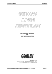
Before mounting the sensor, care must be taken to align the arrow on the top of the
sensor and/or the nib protruding from the front of the base of the sensor parallel with
or along the centerline of the boat. The arrow must be facing forward.
*A second keypad may be added to the system for convenience using a Y-Box Connector.
Contact your dealer or KVH.
11
INSTALLATION
1. Align sensor as shown on left.
arrow point
2. Drill 9/64" holes in the center of the three slots in
the base of the sensor.
3. Put one of the provided 3/4" #10 self-tapping
mounting screws into each of the sensor slots and
tighten down.
Never open the main sensor housing as this will
void your warranty.
Remote Display Unit
After you have carefully chosen a flat surface for the remote display or have cut a
small block of wood to serve as the display's flat mounting plate, follow these instructions carefully:
Note: If it is impossible to reach behind the display to put nuts on the studs, you may have to
build a mounting plate that you can screw in from the top.
1. Tape the template provided at the back of this manual to the bulkhead or area
where you want to mount the display. Use a center punch on the crosshairs
indicated on the template.
2. Drill four 1/4" holes for the enclosed 10-32 studs. Then drill the 9/16" hole for the
cable and connector. The hole must be large enough so that the connector can pass
through. Never try to remove the connector from the cable.
3. Screw the four 10-32 studs into the back of the display. Check if the display slides
easily into the four holes. Correct the hole positions if necessary. Do not force the
display if the holes don't line up!
4. Remove the display, apply some silicone-type sealant around each hole and push
the display all the way in.
5. Use the provided #10 washers and nuts to secure the display. Hand Tighten Only!
Overtightening the screws will damage the display. A dab of silicone on the
threads will keep the nuts from loosening.
12
INSTALLATION
Junction Box
Use the four #6 mounting screws to mount the junction box. The screw holes are only
accessible from the inside of the junction box. To install:
1. Unscrew the four screws on the top of
the junction box and carefully let the
cover hang down.
2. Let the cover hang down, trying not to
strain the ribbon cable that goes to the
power/light switch and the damping
control knob which are located in the
cover.
3. Mark where the holes are in the box and
drill 7/64" holes. Position the junction box
over the holes, insert the four #6 screws
and tighten securely.
Insert screws
in inner holes
4. Replace the cover and tighten the cover screws. The waterproof seal is reinstated
by tightening the cover screws as the mounting screws lie outside the inner rubber
gasket.
Remote Keypad
After you have carefully chosen a relatively flat surface for the remote keypad, follow
these instructions carefully:
Note: If it is impossible to reach underneath the keypad to put nuts on the studs, you may
have to build a mounting plate that you can screw in from the top.
1. Tape the template provided at the back of this manual to the spot where you want
to mount the keypad. Use a center punch on the crosshairs indicated on the template.
2. Drill the two 5/32" holes for the enclosed 6-32 studs. Then drill the 3/4" hole
for the cable. The hole must be large enough so that the cable clamp on the back of
the keypad can pass through. Never try to loosen the cable clamp or remove the
connector from the cable.
3. Screw the two 6-32 studs into the back of the keypad. Check if the keypad slides
easily into the two holes. Correct the hole positions if necessary. Do not force the
keypad if the holes don't line up!
4. Remove the keypad, apply some silicone-type sealant around each hole and push
13
INSTALLATION
the cable and keypad in.
5. Use the provided nuts and washers (6-32) to secure the keypad. Do not overtighten. A dab of silicone on the threads will keep the nuts from loosening.
5. Making the Connections
You are now ready to connect the
components together. The connectors
are easy to use and unable to be
incorrectly fitted. The cables from the
sensor, remote display and remote
keypad each have a connector that
plugs into a port on the front of the
junction box. The junction box is configured as shown, right.
push
push
sensor
cable
add'l display keypad
display cable
cable
power
cable
The connectors snap into the ports. You will hear
the connector click twice when it is fully snapped
onto the port. A connector will only fit onto a port
in one position and is removed by pushing in on
the "grip" surfaced part of the connector and
pulling the connector straight off.
DO NOT TWIST! See illustration, left.
1. Connect the larger grey 12 pin connector coming from the sensor unit to the correct
port on the junction box. This connector will only fit into one port on the junction
box. Push the connector onto the port until it clicks.
2
Connect the cable coming from the remote display to one of the grey remote display ports on the junction box. There are two ports, either may be used.*
3. Connect the black connector coming from the remote keypad to the black port on
the junction box.
14
*If a third remote display is desired, "Y" connectors are available.
INSTALLATION
Now you are ready to connect your system to power, your NMEA 0183 loran/GPS (for
the Nav Repeater Mode) as well as interface it to other instruments on your boat, if
desired. The power cable comes out of the junction box and should be connected as
follows:
1. Connect the red wire to a +12V DC power source* which is fused (1 amp). There is
no internal fuse in the Sailcomp 103AC to protect it from current overloading.
5. Connect the black wire in the power cable to Ground.
There is also a cable coming out of the sensor with 4 wires. These wires connect the
Sailcomp to your NMEA 0183 loran or GPS so that you can activate the Nav Repeater
Mode and also connect to your other electronics that take NMEA 0183 so that they can
access the Sailcomp's heading data. The NMEA lines are used only for interfacing.
Note: Any wires that are not used should be clipped back and insulated from one
another.
The wiring is as follows:
Nav Repeater Mode:
brown
blue
NMEA 0183 In(-)
NMEA 0183 In(+)
NMEA 0183 output to instruments that require heading information:
green
NMEA 0183 Out(+)
orange
NMEA 0183 Out(-)
shield
white
red
black
not used(clipped back)
not used(clipped back)
not used(clipped back)
not used(clipped back)
1. The brown and blue wires are for connecting a NMEA 0183 loran or GPS to your
Sailcomp 103AC so that your Sailcomp 103AC doubles as a nav repeater. If these
wires are not used they should be clipped back and wrapped with electrical tape.
To connect the Sailcomp 103AC to your NMEA 0183 loran or GPS:
The configuration of the signal wiring will vary depending on the brand of loran or
GPS that you have and what parts come with it.
*Use only a +12V DC power source.
15
INSTALLATION
There are three variations:
A. The loran/GPS may have a connector wired to a cable with a pigtail of colored
wires. In this case, consult your loran/GPS owner's manual for the wire color
code.
B. The loran/GPS may supply only a connector without a pigtail of wires. The
NMEA data would then be accessed through the pins on this loran/GPS output
connector. Consult your loran/GPS manual or contact your loran/GPS manufacturer directly to obtain the color code and connector pinout.
C. The loran or GPS may provide nothing at all. In this case, you must consult
your dealer or loran manufacturer to obtain a plug and the required information.
After you have determined the configuration of your loran's or GPS's signal wiring
:
a. Connect the blue wire (NMEA In(+)) to the loran or GPS' NMEA Data Wire
(signal side).
b. Connect the brown wire (NMEA In(-)) to the Signal Ground point on the loran
or GPS unit.
2. The green and orange wires in the power cable are for outputting heading data
from your Sailcomp 103AC to your other instruments with NMEA 0183 data format. If these wires are not used they should be clipped back and wrapped with
electrical tape.
Optional interface outputs that you may have ordered may also be included in this
cable. See separate instructions for any optional interfaces that you have purchased.
Now the unit is ready to power and test.
6. Testing
Testing lets you try out the various functions of the Sailcomp 103AC to make sure
everything is working correctly. Furthermore, all compasses must be checked for accuracy once installed on a boat. The Sailcomp 103AC has an automatic compensation
feature which must be performed after installation to ensure that any errors caused
by your boat's magnetic field are compensated out. (Auto-Compensation, page 17)
16
INSTALLATION— AUTO-COMPENSATION
To test the unit:
1. Turn the power ON at the junction box.
Every time you turn the unit on, the display goes through a segment test where all
segments are lit for 3 seconds.
Do not push any buttons during this segment test. If a button is pushed, an unfamiliar display may appear. If so, turn the power off and on again.
2. Check that the Sailcomp 103AC's digital heading readout agrees approximately
with a known heading or your boat's recently compensated card compass. If it is
not, check to make sure that the sensor is installed top up and that the arrow on
the sensor unit is pointing exactly forward. If the Sailcomp's heading is off and
you have checked that the sensor unit is installed correctly, this indicates that
you have some type of magnetic interference on your boat that must be com pensated out of the Sailcomp 103AC.
You are now ready to compensate your Sailcomp 103AC.
7. Auto-Compensation
ALL COMPASSES MUST BE CAREFULLY CHECKED AGAINST KNOWN REFERENCES AND/OR
BE COMPENSATED BEFORE BEING USED FOR NAVIGATION.
The Sailcomp 103AC's "auto-compensation" capability automatically measures the surrounding magnetic field distortion and compensates it out, thereby removing the
resulting heading errors and giving you a system with better than ±0.5° accuracy in
most cases.
Although each Sailcomp 103AC is carefully calibrated at the factory during manufacturing, you should intentionally auto-compensate it on your boat after installation so that any errors due to metal and magnetism in your boat are removed.
17
INSTALLATION— AUTO-COMPENSATION
The Sailcomp 103AC is shipped from the factory with auto-compensation enabled.
Every time the vessel completes a 360° turn within the time constraints of the system,
the sensor will check its accuracy and recompensate itself if required. Both "hard"
(magnetic) and "soft" (iron) errors are automatically compensated by this procedure.
This procedure will produce excellent accuracies (±1°) even on steel hulls. The
Sailcomp 103AC may recompensate itself during normal boat use anytime the boat
completes a 360° turn within the time constraints and the resulting data is 25% better
than the previously stored data for the sensor.
Important - Read before compensating for the first time!
Intentionally compensating the Sailcomp 103AC at installation is very important to
ensuring its accuracy on your boat and is very easy to do. It involves turning your
boat through two large, lazy circles at a slow, steady speed (the circles may be slightly
out of round or elliptical if necessary). During this procedure, it is critical that the boat
remains level and slow enough (idle speed) so that a full circle takes at least 2 minutes
to complete. You cannot go too slowly, but if you go too quickly at any point while
doing the circles, the sensor is programmed to ignore the data to ensure a perfect compensation.
circles may be clockwise
or counter clockwise.
take 30 seconds or more to
complete 90 degrees.
To Compensate the Sailcomp 103AC:
1. Select a calm day and a clear area without too much current or tide. Watch out for
excessive pitching and rolling, as this can make your boat turn in surges faster than
the Sailcomp 103AC sensor will accept. This procedure should be done under
power, not sail, if possible.
18
INSTALLATION— AUTO-COMPENSATION
2. Turn ON the Sailcomp 103AC and note the heading so that you will roughly know
when you have completed a full circle.
3. There is no Compensation Mode or buttons to push, just steer your boat at a slow,
steady speed (idle speed) through a full circle that takes at least 2 minutes to complete. (Try to time your turn so that it takes 30 seconds or more to turn 90 degrees).
After completing one full circle, continue circling another time. Try slowing down
even more and concentrate on keeping the boat steady and smooth throughout the
360°. Remember, the circles do not need to be perfectly round as long as you go a
complete 360 degrees around.
4. Once you have completed two full circles, your compass should be compensated.
Check to make sure by accessing the "Compensation Display" to review your autocompensation and to check that everything is O.K. (see below)
Accessing the "Compensation Dis-play" for Reviewing
Compensation Data on the Sailcomp Remote.
The Sailcomp 103AC's "Compensation Display" allows you to critically examine the
quality of a compensation, the quality of the sensor's location, how many auto-compensations have occurred, and lets you disable auto-compensation.
To see compensation data on the display:
1. Turn the power ON and wait until the display has gone through self-test.
2. Simultaneously push and hold down the timer and crs(course) buttons until the
display reads "CAL".*
Once "CAL" is displayed, you may release the button. The display will now
continuously roll through the following; "on" indicates that auto-compensation
is enabled. ("oFF" indicates auto-compensation is disabled- see page 22).
*If desired, you may have the "Compensation Display" ON when doing compensation circles,
so you can see when the compass has auto-compensated.
19
INSTALLATION— AUTO-COMPENSATION
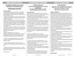
"###" (three digits) are displaying auto-compensation data (a "000" indicates that
the system has not been auto-compensated.)
A. The first digit (1-9) indicates the quality of
the compensation with "9" being the best.
A
B
C
B. The second digit (1-9) indicates the quality
of the magnetic location with "9" being the
best.
C. The third digit is a rollover counter incrementing 1 digit each time the Sailcomp
has accepted a new compensation.
For instance, if you got the above "991" it would indicates that you had a great compensation (9), a great magnetic location (9) and that this is your first compensation (1)*.
If the first digit is lower than a "7", you should turn another 360° to try and get a better
compensation. If the second digit is lower than a "4", you may consider moving the
sensor to a better magnetic location. However, even with a 3 or lower, as long as the
first digit is a "9", you should have ±1° accuracy.
Note: In rare cases, the magnetic field of a particular location may be so different from the factory calibration, that the sensor will re-compensate every 36° while doing a 360° turn. Do not
be alarmed if the compensation display shows that more than one compensation has taken place
or compensation takes place be-fore you complete a circle. Just make sure that you complete
at least one full, slow circle. Multiple compensations are an indication that the sensor is
rapidly receiving better and better information and is updating its stored information for
greater accuracy.
If you ever significantly change your boat's latitude or make changes on your boat
(install new equipment, run cables, etc.) which may affect the boat's magnetic field, or if
you are ever in doubt as to the Sailcomp 103AC's accuracy, simply follow the autocompensation procedure on pages 17-19 to be assured that it is accurate at all times.
To exit the "Compensation Display" apply two short pushes to the crs (course) button
and the display will return to Compass Mode.
20
*The last digit rolls over to a "1" after 9 compensations.
Alignment Error Adjustment
Now, you should check to see how well you aligned the sensor parallel with the centerline of your boat. To check the sensor's alignment, take a couple of known runs from
a chart* and compare the magnetic bearing on the chart with the heading readout on
the Sailcomp display. If the Sailcomp reading is off by the same amount of degrees in
a couple of directions, then every reading around the compass will be off by exactly
that amount. This indicates that the sensor is not pointing exactly forward in respect
to the bow of your boat. Rather than rotating the sensor slightly to adjust for this
Alignment ("A") error, you can adjust it electronically.
1. Enter into the "Compensation Display" as
indicated on pages 19-20. To adjust for "A"
error, apply a short push to the cr (course)
button. The display will show "AoF", indicating that you have entered the "Alignment
Offset" section of the software.
2. To examine the value for the "A" offset,
apply a short push to the nav button. The display will flash the current value of the
offset. Offset is set at the factory to 00°.
3. If the heading is "low" (or to the minus(-) side on all headings), you need to add
offset. To increase the "A" offset, hold the nav button down until the desired
plus(+) value is displayed.
4. If the heading is "high" (or to the plus (+) side on all headings), you need to subtract offset. To decrease the "A" offset, hold the port button down until the desired
minus(-) value is displayed.
5. To change the offset, use the nav and port buttons to scroll up or down the correct
number of degrees.
6. To save the "A" offset and return to compass mode, apply a short push to the crs
(course) button. The new "A" offset will be stored in memory and the display will
return to compass mode. Notice that the Sailcomp's headings will now match the
known headings.
Note: Do not turn the 103AC's power OFF for at least 10 seconds after exiting the Alignment
Offset Mode to allow the system to update and record the data in long term memory.
*The Sailcomp 103AC is more accurate than any compass you may have on your boat, so do
not use another compass as a reference.
21
INSTALLATION— AUTO-COMPENSATION
Example: After auto-compensation, a comparison of a couple of Sailcomp 103AC
headings with "runs" from a chart indicate that the Sailcomp is reading 2° lower than it
should be. For instance, instead of displaying 180° it is displaying 178°. This means
that the sensor is pointing to the left of the boat's centerline by 2°. To correct this, enter
into the "Compensation Display" by simultaneously pushing the timer and crs (course)
buttons until "CAL" appears. Now enter the "Alignment Offset" section of the software
by pushing and releasing the crs (course) button. Apply a short push to the nav button
to examine the value entered for "A" Offset (from the factory, this will be "00"). You
need to add 2° to all headings to adjust for the "A" error, so push and hold down the
nav button until "02" appears on the display and then release the button. Exit by pushing the crs (course) button again. Now, when you point to your reference of 180°, the
Sailcomp will display 180°.
Very Important! Once the Alignment Error is adjusted, it is stored in memory and
never has to be re-adjusted unless the sensor is moved.
Disabling/Enabling Auto-Compensation
With auto-compensation disabled, your compass will be using the last compensation
that has been stored, but will be unable to update itself if something changes in the
boat's magnetic environment, etc. In essence, it is locked.
If you want to disable or enable auto-compensation, enter into the "Compensation
Display" by simultaneously pressing the timer and crs (course) buttons until "CAL"
appears. Release the buttons and "on" appears followed by 3 digits (###). Hold down
the port button and the display will toggle between "oFF" and "on". Release the button while "oFF" is displayed to disable auto-compensation.
Important Note: Be sure that Damping Knob is in Position 1 while disabling or
enabling auto-compensation.
Auto-compensation may be turned on/off in the Sailcomp 103AC whenever desired.
Just be aware of what state it is in. You may check this at any time by entering into the
"Compensation Display" and watching whether "on" or "oFF" is displayed.
To exit the "Compensation Display", apply two short pushes to the crs (course)
button. Whatever was flashing on the display - "on" or "oFF" - will be activated and
the display will return to compass mode.
22
II. SAILCOMP 103AC FEATURES
1. Sailcomp Features
The Sailcomp 103AC is very straightforward in its operation. The junction box controls on/off, the damping and the light. The remote keypad has five buttons which
control the system's 5 modes: Trend Mode, Off-Course Mode, Nav Repeater Mode,
Head/Lift Mode and Starting Timer Mode.
Port and Stbd: The port and stbd
buttons are for the Head/Lift Mode.
They are used to enter your port and
starboard tack averages for racing.
port
nav
timer
crs
stbd
Nav: When connected to a NMEA 0183 navigation unit such as a loran or GPS, the
nav button turns your Sailcomp 103AC into a loran or GPS repeater. Once connected
to a loran or GPS, pushing the nav button makes the Sailcomp 103AC go into Nav
Repeater Mode. The display will alternate every 2 seconds between Bearing to
Waypoint and Distance to Waypoint in nautical miles. Cross Track Error is shown in
.05 nm increments to port or starboard on the upper part of the display.
Note: If the Sailcomp is not connected to a loran/GPS, if the loran/GPS is not ON, or if waypoints are not entered into the Loran/GPS, the Sailcomp 103AC display will display "- - - "
when the nav button is pushed.
Timer: The timer button puts the system into Starting Timer Mode and displays the
time remaining until the start of a race.
Crs (Course): The crs button serves two main functions. It sets the course that you
want to use as a reference for the off-course indicator and it also allows you to change
between Trend Mode and Off-Course Mode.
2. Damping Control
The damping knob on the junction box controls the averaging period over which the
compass displays information. Damping does not diminish the accuracy of the
Sailcomp 103AC like it does in a conventional compass. The damping levels range
from 1-4, with damping 1 a nearly instantaneous readout and damping 4 about 14 seconds of averaging. On most boats, damping 2 or 3 is the most stable and responsive.
If you are in rough seas, you may want to increase the damping so that you get a more
stable display. In calm water or at lower speeds, you may want to decrease the damping so that the display responds more quickly.
23
III. SAILCOMP 103AC MODES
The Sailcomp 103AC's 5 modes: Trend Mode, Off-Course Mode, Nav Repeater
Mode, Head/Lift Mode and Starting Timer Mode are all explained in detail on the following pages.
1. Trend Mode
Every time the compass is turned ON, it automatically goes into Trend Mode. "Trend"
refers to the rate of turn. The purpose of the trend indicator is to help keep you oriented in terms of how fast you are turning to the left or to the right -- something that can
be difficult to perceive with a digital readout alone.
2. Off-Course Mode
Trend Mode only shows your rate of turn. It does not show you how far off-course
you are. To do that, you need to enter a reference course (so the Sailcomp knows
where you want to go). You can enter a reference course only when you are in the OffCourse Mode. In the Off-Course Mode, your present heading is compared to a reference heading that you have selected and the difference is displayed in degrees with
segments to the left or right on the upper analog display. The Off-Course Mode is very
useful for sailing long or short distances as it enables you to set a rhumb line and then
sail to the upper analog display, steering to left or right to keep the segments zeroed out.
To use the Off-Course Mode:
1. Turn the Sailcomp ON. You are now in Trend Mode.
2. The first push on the crs (course) button puts you into Off-Course Mode. The
word "Crs" appears where the digits normally are, to tell you that you are now in
Off-Course Mode. The Sailcomp will use whatever heading was previously stored
as the reference heading. (The default setting is "000°" and resets to this every time
the unit is turned off).
1 port and 1 stbd segment appear on
each side of upper (analog) display.
Display freezes on selected heading.
Set Course = 342°
24
MODES — OFF COURSE / TREND
3. Point your boat in the direction you want to go, steering to the digital heading for
your desired course. When the desired course appears on the display, push the crs
(course) button again. The upper display will show a single segment on either side
of center to indicate that this is now the reference heading. The digits momentarily
freeze on the new heading while you hold the button down. This will now be the
reference course stored in the Sailcomp's memory (see illustration on facing page).
Do not hold the button down for more than two seconds or the system will
return to Trend Mode.
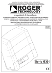
In Off-Course Mode, the digital display continues to display the current compass heading, while the upper analog display graphically shows how far off course the current
heading is to your reference course. When you steer off of the reference course, you
will see segments to the left and right on the upper part of the display corresponding
to how many degrees to port or starboard you are off your reference course's rhumb
line. By centering the upper display so that there are no segments to the left or right,
you will be steering to your reference course. (see following illustrations)
on course - course = 342°
off course to port 15°
off course to starboard 4°
4. If you want to enter a new heading, just press the crs button again. Once you are in
the Off-Course Mode, each subsequent push will enter the compass' current heading as the reference course. The upper display will instantly lock into this new set
course.
Note: Every time you turn OFF the Sailcomp 103AC, it will reset to a default reference course
setting of 000°.
Getting Back to Trend Mode
Once you are in Off-Course Mode, each time you
push the crs button, a new reference heading is
entered. However, if you hold the button down for
two seconds or more, the compass will go back into
Trend Mode. The word "Trd" appears where the
digits normally are, to tell you that you are now in
Trend Mode.
25