1
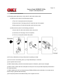
Thank You for purchasing this
Factory Service Manual on EBAY
from PCTECHINFO!
Click Here for more Factory Service
Manuals for other Computer and
Printer / Copier Manufacturers
from PCTECHINFO!
Service Guide OKIPAGE 18/18n
Chapter 0 Introduction
Front Cover
Oki Data
Service Guide
OKIPAGE 18 and 18n
Adobe Acrobat printable reference copy
of the OKIDATA Service Training Manual.
01/26/2000
Note: This Adobe Acrobat version of the Okidata Service Training Manual was built with the pictures
rendered at 300 dpi, which is ideal for printing, but does not display well on most displays.
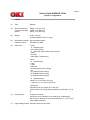
Table of Contents
Page
Service Guide OKIPAGE 18/18n
0 Introduction
Preface
1 Configuration
Configuration
....1.1 System Configuration
....1.2 Printer Configuration
....1.3 Optional Configuration
....1.4 Specification
....1.5 Safety Standards
........1.5.1 Certification Label
........1.5.2 Warning Label
2 Operation Description
2.0 Operation Description
2.1 Main Control Board (BOARD-FFF)
2.2 Power Supply Unit
2.3 Electro-photographic Process
....2.3.1 Electro-photographic process mechanism
....2.3.2 Electro-Photographic process
....2.3.3 Process operation descriptions
....2.3.4 Revision of LED Head Illumination
2.4 Paper Jam Detection
2.5 Cover Open
2.6 Toner Low Detection
2.7 Stacker-full Detection
2.8 Page Size Detection
3 Parts Replacement
Parts Replacements
....3.1 Precautions for Parts Replacement
....3.2 Parts Layout
........Figure 3-1
........Figure 3-2
........Figure 3-3
....3.3 How to Change Parts
........3.3.1 Face-up Stacker Assy
........3.3.2 Contact Assy
........3.3.3 DC Fan Motor
........3.3.4 OP Panel Assy
........3.3.5 Board - FFF
........3.3.6 Stacker Assy, Damper Arm, Cover Rear
........3.3.7 Sensor Stacker Full
........3.3.8 Cable cover (guide film)
........3.3.9 Damper
........3.3.10 Feeder Unit - Front
........3.3.11 Roller Assy - Regist
........3.3.12 Motor - Main
........3.3.13 Guide Assy - Eject
........3.3.14 Heat Assy
........3.3.15 Roller feed (C)
........3.3.16 Roller Assy - BK
........3.3.17 Roller Assy - Feed
1
2
3
4
5
6
7
8
9
10
11
12
13
14
15
16
17
18
19
20
21
22
23
24
25
26
27
28
29
30
31
32
33
34
35
36
37
38
39
40
41
42
43
44
45
46
Table of Contents
........3.3.18 LED Head
........3.3.19 Paper cassette, ROLLER Assy - Feed, ROLLER
Assy - Hopping
........3.3.20 Frame Assy - Separation
........3.3.21 Transfer Roller / TR Gear / TR Bearing
........3.3.22 EP lock shaft
........3.3.23 LEVER Assy - Out Sensor
........3.3.24 Toner sensor lever
........3.3.25 Paper sensor lever
........3.3.26 Inlet sensor lever
........3.3.27 Power supply unit
........3.3.28 Lever-Paper end & Lever-Paper near end
........3.3.29 Guide Assy - Cassette (L)
........3.3.30 Guide Assy - Cassette (R)
4 Adjustment
4.0 Adjustment
....4.1 Maintenance Modes and Functions
........4.1.1 User maintenance mode
........4.1.2 System maintenance mode
........4.1.3 Engine maintenance mode
........4.1.4 EEPROM initialization
....4.2 Adjustment When Replacing a Part
........4.2.1 Setting LED Head Drive Time
........4.2.2 Destination setting
........4.2.3 Setting of LED head drive time
5 Periodical Maintenance
5.1 Periodic Maintenance
5.2 Cleaning
....5.2.1 Cleaning the LED Lens Array
....5.2.2 Cleaning the Plastic Film
6 Troubleshooting Procedures
6.1 Troubleshooting Tips
6.2 Check Points Before Correcting Image Problems
6.3 Notes When Correcting Image Problems
6.4 Preparation Before Troubleshooting
6.5 Troubleshooting Flowchart
....6.5.1 Status Monitor Message List
....6.5.2 LCD message troubleshooting
........(1) The printer does not work normally after being turned
on.
........(2) Paper jams
............(2)-1 Paper input jam (1st tray)
............(2)-2 Paper input jam (front feeder)
............(2)-3 Paper feed jam
............(2)-4 Paper exit jam
........(3) Paper size error
........(4) Fuser unit error (ERROR 71), (ERROR 72), (ERROR
73)
........(5) I/F time-out between printer and optional tray (ERROR
81)
........(6) I/F time-out between printer and Duplex Unit (ERROR
83)
Page
47
48
49
50
51
52
53
54
55
56
57
58
59
60
61
62
63
64
65
66
67
68
69
70
71
72
73
74
75
76
77
78
79
80
81
82
83
84
85
86
87
88
89
90
Table of Contents
........(7) I/F time-out occurs between the printer and the
operator panel (ERROR 80)
........(8) Message cannot be received through the parallel
interface
........(9) Message cannot be received through the serial
interface
........(10) Data cannot be received through the OKI HSP
interface
........(11) Synchronous serial I/O error (ERROR 74)
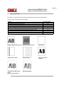
....6.5.3 Image Troubleshooting
........(1) An image is light or blurred entirely
........(2) Dark background density
........(3) Black paper is output
........(4) Black belts or stripes in the vertical direction
........(5) Cyclic error
........(6) Print voids
........(7) Poor fusing
........(8) White belts or streaks in the vertical direction
........(9) Snowy print of high density pattern
........(10) Blotchy faded print
........Contents - Figure 6-5
........Contents - Figure 6-6
7 Wiring Diagram
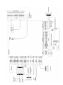
7.1 Interconnect Signal Diagram
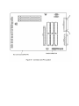
7.2 PCB Layout
....7.2.1 Main Control Board (HBY PCB)
....7.2.2 Power Supply Board (120V/230V)
....7.2.3 Power supply board (High voltage)
....7.2.4 Flash ROM module (BOARD-FSL or BOARD-FSL-2)
7.3 Resistance Check
7.4 Program Font/ROM Location
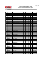
8 Parts List
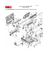
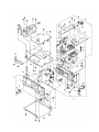
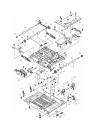
Figure 8-1 Printer Unit
Figure 8-2 Frame - Main Unit
Figure 8-3 Base Unit
A Centronics Parallel Interface
Parallel Interface
B RS-232C Serial Interface
RS-232C Serial Interface
C Duplex Unit Maintenance (option)
1. OUTLINE
....1.1 Functions
....1.2 External View and Component Names
2.0 Mechanism Description
....2.1 General Mechanism
....2.2 JAM Release Mechanism
....2.3 Removing/Installing Duplex Unit
3.0 Parts Replacement
....3.1 Precautions Concerning Parts Replacement
....3.2 Parts Layout
....3.3 Parts Replacement Methods
Page
91
92
93
94
95
96
97
98
99
100
101
102
103
104
105
106
107
108
109
110
111
112
113
114
115
116
117
118
119
120
121
122
123
124
125
126
127
128
129
130
131
132
Table of Contents
........3.3.1 Board-LEX
........3.3.2 Connector (IMSA-9714N-14A)
........3.3.3 Photo Sensor
........3.3.4 SOLENOID Assy
........3.3.5 Motor
4.0 Troubleshooting
....4.1 Precautions Prior to the Troubleshooting
....4.2 Preparations for the Troubleshooting
....4.3 Troubleshooting Method
........4.3.1 LCD Status Message List
........4.3.2 Troubleshooting Flow
5.0 Connection Diagram
....5.1 Interconnection Diagram
....5.2 PCB Layout
6.0 Parts List
Table 6-1 Duplex Unit
D Second / Third Paper Feeder Maint (option)
1.0 Outline
....1.1 Functions
....Appearance and Parts Name
2.0 Description of operation
....2.1 Driving Mechanism
....2.2 Hopper Mechanism
3.0 Parts Replacement
....3.1 Precautions Concerning Parts Replacement
....3.2 Parts Layout
....3.3 Parts Replacement Methods
........3.3.1 Roller assy hopping, Roller assy feed
........3.3.2 Cover front assy
........3.3.3 Board-BBB
........3.3.4 Lever paper end, Lever paper near end
........3.3.5 Motor
........3.3.6 Connector (IMSA-9714N-14B), Connector
(IMSA-9714N-14A)
........3.3.7 Frange pulley, pulley Idle, Mini pitch belt, Plate Earth
shaft, Gear double, Tray switch assy
........3.3.8 Roller feed
........3.3.9 Bracket sub roller
........3.3.10 Frame side (L) assy
........3.3.11 Frame side (R) assy
4.0 Troubleshooting
....4.1 Precautions Prior to the Troubleshooting
....4.2 Preparations for the Troubleshooting
....4.3 Troubleshooting Method
........4.3.1 LCD Status Message List
........4.3.2 Troubleshooting Flow
5.0 Connection Diagram
....5.1 Interconnection Diagram
....5.2 PCB Layout
6.0 Parts List
E Multi-Purpose Feeder Maintenance
Page
133
134
135
136
137
138
139
140
141
142
143
144
145
146
147
148
149
150
151
152
153
154
155
156
157
158
159
160
161
162
163
164
165
166
167
168
169
170
171
172
173
174
175
176
177
178
179
Table of Contents
1.0 Outline
....1.1 Functions
....1.2 External View and Component Names
2.0 Mechanism Description
....2.1 General Mechanism
....2.2 Hopper Mechanism
3.0 Parts Replacement
....3.1 Precautions Concerning Parts Replacement
....3.2 Parts Layout
....3.3 Parts Replacement Methods
........3.3.1 Separator
........3.3.2 AOLE-PCB
........3.3.3 Square-shaped connector
........3.3.4 Hopping Motor
........3.3.5 Planet gear
........3.3.6 Roller B
........3.3.7 Roller A
........3.3.8 Mini pitch belt & Feed roller
4.0 Troubleshooting
....4.1 Precautions Prior to the Troubleshooting
....4.2 Preparations for the Troubleshooting
....4.3 Troubleshooting Method
........4.3.1 LCD Status Message List
........4.3.2 Troubleshooting Flow
5.0 Connection Diagram
....5.1 Interconnection Diagram
....5.2 PCB Layout
6.0 Parts List
Page
180
181
182
183
184
185
186
187
188
189
190
191
192
193
194
195
196
197
198
199
200
201
202
203
204
205
206
207
Page: 1
Service Guide OKIPAGE 18/18n
Chapter 0 Introduction
Preface
This maintenance manual describes the field maintenance methods for OKIPAGE 18.
This manual is written for use by maintenance personnel. Note, however, that the user should refer to the USER'S
MANUAL for methods of handling and operating the equipment.
Copyright 1998, Okidata, Division of OKI America, Inc. All rights reserved. See the OKIDATA Business Partner
Exchange (BPX) for any updates to this material. (http://bpx.okidata.com)
Page: 2
Service Guide OKIPAGE 18/18n
Chapter 1 Configuration
Configuration
System Configuration
Printer Configuration
Optional Configuration
Specification
Safety Standards
Copyright 1998, Okidata, Division of OKI America, Inc. All rights reserved. See the OKIDATA Business Partner
Exchange (BPX) for any updates to this material. (http://bpx.okidata.com)
Page: 3
Service Guide OKIPAGE 18/18n
Chapter 1 Configuration
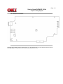
1.1 System Configuration
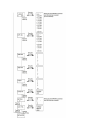
The OKIPAGE 18 consists of control and engine blocks as the standard configuration (See Figure 1-1).
In addition, the following options are also available.
Figure 1-1
Copyright 1998, Okidata, Division of OKI America, Inc. All rights reserved. See the OKIDATA Business Partner
Exchange (BPX) for any updates to this material. (http://bpx.okidata.com)
Page: 4
Service Guide OKIPAGE 18/18n
Chapter 1 Configuration
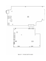
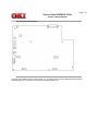
1.2 Printer Configuration
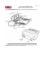
The printer unit consists of the following hardware components:
l
Electro-Photographic Processor
l
Paper Feeder
l
Controller
l
Operator panel
l
Power supply unit
Figure 1-2 is the configuration of the printer unit.
Copyright 1998, Okidata, Division of OKI America, Inc. All rights reserved. See the OKIDATA Business Partner
Exchange (BPX) for any updates to this material. (http://bpx.okidata.com)
Page: 5
Service Guide OKIPAGE 18/18n
Chapter 1 Configuration
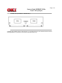
1.3 Optional Configuration
1
Multi Feeder
2
Second / Third Paper Feeder
3
DUPLEX Unit (Optional)
4
D-RAM SIMM module (72 pin
SIMM, 16 MB/32MB, EDO SIMM
type)
5
Flash ROM module (72 pin SIMM, (See 7.2 (1) for where to install).
4MB/8MB)
(See 7.2 (1) for where to install).
Copyright 1998, Okidata, Division of OKI America, Inc. All rights reserved. See the OKIDATA Business Partner
Exchange (BPX) for any updates to this material. (http://bpx.okidata.com)
Page: 6
Service Guide OKIPAGE 18/18n
Chapter 1 Configuration
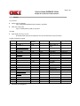
1.4 Specification
(1)
Type:
Desktop
(2)
Outside dimensions
(excludes protruding
portion)
Height: 13.0" (331 mm)
Width: 14.4" (366 mm)
Depth: 18.2" (462 mm)
(3)
Weight
42 lbs. (19.0 kg)
If installed Duplex 47 lbs. (21.3 kg)
(4)
Development method Dry electrophotography
Exposure method
LED stationary head
(5)
Paper used
<Type>
l Standard paper
- Xerox 4200 (20 lbs)
l Application paper (manual face-up feed)
- Label
- Envelope
- OHP paper (Transparency)
<Size>
l Standard sizes
- Letter
- Legal
- Executive
- Envelope (with Duplex printing)
- A4
- A5 (without Duplex printing)
- B5 (without Duplex printing)
- A6 (without Duplex printing)
l Applicable sizes
-Width: 3.4" to 8.5" (86 to 216 mm)
- Length: 5.5" to 14" (140 to 355.6 mm)
<Thickness>
2
Automatic feed: 16 to 28 lbs (60 to 105 g/m )
- Manual feed: Label, OHP paper (transparency), Envelope, 16~36
lb.
(6)
Printing speed:
First print: 8 seconds
Continuous print: 8 sheets/min. [at duplex print: 9 sheets/min]
o
o
Warm-up time: 90 seconds (at room temperature 77 F (25 C) and
rated voltage (120 VAC)
(7)
Paper feeding method Automatic feed or manual feed
(8)
Paper delivery method Face down/face up
(9)
Resolution
600 dpi x 600 dpi (default)
600 x 1200 dots/inch
(10) Power input
120 VAC +/-15%
230 VAC +/-10%
(11) Power consumption
Peak: Approx. 820W
Typical operation: Approx. 350W
Idle: Approx. 95W
Power save mode: Approx. 25W
(12) Temperature and
humidity
Temperature
Humidity
Maximum wet bulb
temperature
Minimum difference of
wet and dry bulb
temperature
In operation
50 - 90
(10-32)
Power off mode
32-110
(0-43)
During Storage
14-110
(-10 - 43)
20 - 80
77
(25)
10-90
80.4
(26.8)
10-90
-------
35.6
(2)
35.6
(2)
-------
Unit
o
F
o
( C)
% RH
o
F
o
( C)
o
F
o
( C)
Notes:
1. Storage conditions specified above apply to printers in packed condition.
2. Temperature and humidity must be in the range where no condensation occurs.
(13) Noise
During operation: 52 dBA or less (without second tray)
52 dBA or less (with second tray)
At standby: 45 dBA or less
Power save mode: 43 dBA or less
(14) Consumables
Toner cartridge kit - 6,000 (5% duty)
Image drum cartridge - 30,000 (at 5% density, continuous printing)
Copyright 1998, Okidata, Division of OKI America, Inc. All rights reserved. See the OKIDATA Business Partner
Exchange (BPX) for any updates to this material. (http://bpx.okidata.com)
Page: 7
Service Guide OKIPAGE 18/18n
Chapter 1 Configuration
1.5 Safety Standards
1.5.1 Certification Label
1.5.2 Warning Label
Copyright 1998, Okidata, Division of OKI America, Inc. All rights reserved. See the OKIDATA Business Partner
Exchange (BPX) for any updates to this material. (http://bpx.okidata.com)
Page: 8
Service Guide OKIPAGE 18/18n
Chapter 1 Configuration
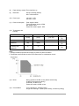
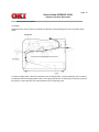
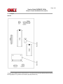
1.5.1 Certification Label
The safety certification label is affixed to th eprinter in the position below.
Copyright 1998, Okidata, Division of OKI America, Inc. All rights reserved. See the OKIDATA Business Partner
Exchange (BPX) for any updates to this material. (http://bpx.okidata.com)
Page: 9
Service Guide OKIPAGE 18/18n
Chapter 1 Configuration
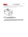
1.5.2 Warning Label
The warning label is affixed to the portion which may cause an injury to human body. Follow the instructions on
warning labels during maintenance.
Copyright 1998, Okidata, Division of OKI America, Inc. All rights reserved. See the OKIDATA Business Partner
Exchange (BPX) for any updates to this material. (http://bpx.okidata.com)
Page: 10
Service Guide OKIPAGE 18/18n
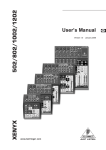
Chapter 2 Operation Description
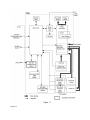
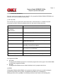
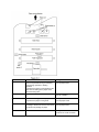
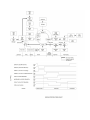
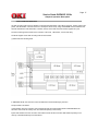
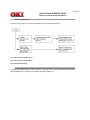
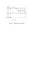
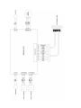
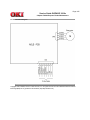
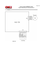
2.0 Operation Description
OKIPAGE 18 consists of a main control board, power supply unit (120V/230V), power supply unit (high
voltage) and operator panel and an electro-photographic process mechanism.
The control board receives data through a host I/F, decodes and edits the data, and stores the edited data
in a memory. After completing edition of one page of data, it references the font memory and generates bit
data on the same memory. At the same time, it transfers the bit image data to an LED head in units of one
dot line.
The electro-photographic process mechanism prints data on paper.
The operator panel is used for operations and status display.
Fig. 2-1 shows an OKIPAGE18 block diagram.
Figure 2-1 OKIPAGE 18 block diagram
Copyright 1998, Okidata, Division of OKI America, Inc. All rights reserved. See the OKIDATA Business Partner
Exchange (BPX) for any updates to this material. (http://bpx.okidata.com)
Page: 11
Service Guide OKIPAGE 18/18n
Chapter 2 Operation Description
2.1 Main Control Board (BOARD-FFF)
The main control board consists of a one-chip CPU, LSI, program/font ROM's, DRAM's, EEPROM, host
interface circuit, and a mechanism driving circuit.
(1) One-chip CPU
The one-chip CPU is a custom CPU (32-bit internal bus, 32-bit external bus, 120-MHz clock) that
incorporates an RISC CPU and its peripheral devices, and has the following functions.
Built-in Device
Function
Chip select controller
Bus controller
DRAM controller
Control peripheral LSI, ROM, DRAM and I/O device.
DMA controller
Transfer of data Host I/F to RAM
Serial interface controller
Control of RS232C serial interface.
Parallel interface controller
Control of Centronics parallel interface.
Timer
Generates various control timings for monitoring paper
feeding and a paper size.
Serial I/O port
Inputting of various signals
Outputting of various control signals
I/O port
Inputs and outputs the sensor signals and motor signals, etc.
Also performs I/O for EEPROM.
Motor driver controller
Control of Main Motor.
Image processing circuit
Executes the image data process for printing.
(2) Program/font ROM's
l
l
PCL ROM
The program/font ROM's store the HP LJ5 emulation program and various types of font. MASK ROM
is used as the program/font ROM's.
PS ROM
The program/font ROM's store the Adobe PostScript Level 2 program and its fonts.
(3) DRAM
16-Megabyte DRAM (64 Mbit DRAM x 2) is mounted as resident memory to be used for storing the
program and providing various buffers. This DRAM is expandable up to 128 Mbytes by
adding expansion memory (SIMMs). This DRAM provides the areas shown in the following table.
Memory area
System area
Raster buffer
Receive buffer
Page buffer
DLL/macro
buffer
Font cache
buffer
Use
Working area used for the program
Stores converted bit image data
Stores temporarily the data
received from the host interface
Adds print information to the
analyzed receive data and stored
the resulted data.
Stores soft fonts and macro data.
Stores bit map fonts generated by
the font rasterizer based on
scalable font information.
Memory capacity setting
MENU
Expansion RAM
Fixed
Fixed
Enable
Expandable
Enable
Expandable
----
Expandable
----
Expandable
Enable
Expandable
(4) EEPROM
EEPROM has a 16-kbit capacity and stores the following data.
l
l
l
Menu data
Various counter data (page counter, drum counter, fuser counter, etc.)
Adjustment parameters (LED head drive time, print start position, etc.)
(5) LSI (LZ9FF22)
Built in device
Serial I/O port
Function
Control of serial interface between controller and 2nd tray,
3rd tray, Multi purpose feeder
Control of serial interface between controller and Duplex unit
Motor drive controler Control of Hopping motor
I/O Port
Inputting of various sensor signals
Outputting if various control signals
(6) Host interface
This printer has the following interfaces to the host.
l
l
l
Centronics bidirectional parallel interface
RS232C interface
OKI HSP interface (Option)
The single effective interface or the automatic interface select mode can be selected using the menu. If
the busy state of the printer continues for a long time period, the buffer near-full control releases the busy
status at constant intervals even if the host side is busy so not to cause the interface time-out at the host
side.
(a) Centronics bidirectional parallel interface
This is an interface conforming to IEEE-1284 and provides either of unidirectional and bidirectional
communications according to each of the following communication modes.
l
Compatibility mode
Unidirectional communications from the host to the printer.
l
Nibble mode
This mode transmits 4-bit wide data from the printer to the host. In this mode, each 1-byte data is
transferred in the form of two nibbles using ERROR, BUSY, FAULT, and SELECT signal leads. This
mode can provide the bidirectional operation in combination with the compatibility mode.
l
ECP mode
This mode provides the asynchronous bidirectional interface and transmits and receives 1-byte data
using eight data signal leads under the semi-duplex control by the host.
When the power is turned on, the compatibility mode is automatically selected. The change to another
mode from the compatibility mode is made through negotiation. (When the BI DIRECTION is set to
ENABLE in the menu, this change can be performed.) (For the electrical/physical characteristics of this
interface, see APPENDIX B)
(b) RS232C serial interface
The following protocol is supported for the serial interface conforming to EIA RS232C.
l
l
l
READY/BUSY (DTR HI or DTR LO)
X-ON/X-OFF
RBST X-ON
(For the electrical/ physical characteristics of the interface, see APPENDIX B)
(c) OKI HSP interface (Option)
This interface (slot) is an OKI unique universal interface that provides the platform to connect option
boards (including those supplied by third party venders) such as the LAN connection expansion board and
SCSI expansion board.
Any expansion boards compatible with this interface can be mounted on the Control board in the
piggyback board without modifying the program at the printer side. The conceptual diagram of the OKI
HSP interface is shown in Figure 2-2.
(For the electrical/physical characteristics of the OKI HSP interface, see the OKI HSP interface technical
manual.)
(7) RAM module
l
Pin layout
l
Basic specification
- Type:
- Access time:
- Capacity:
- Parity:
72 pins Standard SIMM (32 bits buss width)
[Note: EDO SIMM type]
60ns, 70ns, 80ns, 100ns
16 or 32 MB
None
(8) Flash ROM module
l
Pin layout
l
Basic specification
- Type:
- Access time:
- Capacity:
72 pins SIMM (32 bits buss width)
90ns
4 or 8 MB
Copyright 1998, Okidata, Division of OKI America, Inc. All rights reserved. See the OKIDATA Business Partner
Exchange (BPX) for any updates to this material. (http://bpx.okidata.com)
Page: 12
Service Guide OKIPAGE 18/18n
Chapter 2 Operation Description
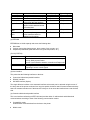
2.2 Power Supply Unit
The power supply unit consists of an AC filter circuit, a low voltage power supply circuit, a high voltage power supply
circuit, heater drive circuit, and photosensors.
(1) Low voltage power supply circuit
This circuit generates the following voltages.
Output voltage
+5 V
+30 V
+8 V
-8 V
+3.8 V
Use
Logic circuit supply voltage
Motor and fan drive voltage and source voltage for high-voltage supply
Reset circuit, RS232C Line voltage
RS232C Line voltage
LED HEAD supply voltage
(2) High voltage power supply circuit
This circuit generates the following voltages necessary for electro-photographic processing from +30 V according to
the control sequence from the control board. When cover open state is detected, +30 V supply is automatically
interrupted to stop the supply of all the high-voltage outputs.
Output
Sub-CH
CH
DB
SB
TR
CB
Voltage
-15 uA
-1.30 KV
-220 V+300 V
-450 V
+4 KV/-1.3 kV
+450 V-1350V
Use
Voltage applied to Sub charging roller
Voltage applied to charging roller
Voltage applied to developing roller
Voltage applied to toner supply roller
Voltage applied to transfer roller
Voltage applied to cleaning roller
Remarks
Variable + Only
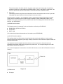
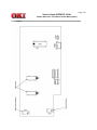
(3) Photosensor
The photosensor mounted on this power supply unit supervises the paper running state during printing.
Figure 2-3 shows the sensor layout diagram.
Sensor
Function
Inlet sensor
Detects the leading part of the paper and
ON: Paper exists
gives the supervision timing for switching
OFF: No paper exists
from hopping operation to feeding
operation.
Supervises the paper running state and the
paper size according to the paper reach
time and running time.
Detects the form width.
ON: A4 or larger
OFF: A4 or smaller
Inlet sensor 2
Sensing state
Paper sensor
Detects the leading part of the paper.
Supervises the paper running state.
ON: Paper exists
OFF: NO paper exists
Outlet sensor
Supervises the paper feed and size
ON: Paper exists
according to the time of arrival to the sensor OFF: No paper exists
and the time of passage of paper.
Toner low sensor
Detects the lack of toner.
ON long: Toner low exists
OFF short: No Toner low exists
Copyright 1998, Okidata, Division of OKI America, Inc. All rights reserved. See the OKIDATA Business Partner
Exchange (BPX) for any updates to this material. (http://bpx.okidata.com)
Page: 13
Service Guide OKIPAGE 18/18n
Chapter 2 Operation Description
2.3 Electro-photographic Process
2.3.1 Electro-photographic process mechanism
2.3.2 Electro-photographic process
2.3.3 Process operation descriptions
2.3.4 Revision of LED Head Illumination
Copyright 1998, Okidata, Division of OKI America, Inc. All rights reserved. See the OKIDATA Business Partner
Exchange (BPX) for any updates to this material. (http://bpx.okidata.com)
Page: 14
Service Guide OKIPAGE 18/18n
Chapter 2 Operation Description
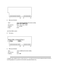
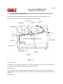
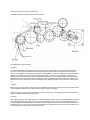
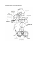
2.3.1 Electro-photographic process mechanism
This mechanism prints image data from the control board on the paper by electro-photographic process.
The Figure 2-4 shows the layout of the electro-photographic process mechanism.
(1) Image drum unit
The image drum unit consists of a sensitive drum, a charger, and a developer. The unit forms a toner image on the
sensitive drum, using a electrostatic latent image formed by the LED head.
(2) Hopping motor
This motor is a pulse motor of 48 steps/rotation that is two-phase excited by the signal from the control board. It
drives the hopping roller of the first tray and the front feed roller via two one-way clutches according to the direction
of rotation.
(3) Motor-Main
This motor is a pulse motor of 72 steps/rotation that is two-phase excited by the signal from the control board and is
the main motor of this mechanism.
(4) Clutch (for Registration)
Switches the transfer of power to Roller Registration if necessary depending on the power Motor-Main and
instructions from the control PCB.
(5) Clutch (for Feed Roller)
Switches the transfer of power to Feed Roller if necessary depending on the power from Motor-Main and instructions
from the control PCB.
(6) LED head
Image data for each dot line from the control board is received by the shift register and latch register. The 4992
LEDs are driven to radiate the image data to the image drum.
(7) Fuser
The fuser consists of a heater, a heat roller, a thermistor and a thermostat. An AC voltage from the power supply
board is applied to the heater under the control of the HEATON signal from the control board. This AC voltage heats
the heater. The control board supervises the heat roller temperature via the thermistor, and regulates the heater
roller at a predetermined temperature (185 °C : Normal paper, MEDIA TYPE = MEDIUM) by connecting or
disconnecting the AC voltage supply to the heater. If the heater roller temperature rises abnormally, the thermostat
of the heater voltage supply circuit is activated to cut the AC voltage supply forcibly.
Copyright 1998, Okidata, Division of OKI America, Inc. All rights reserved. See the OKIDATA Business Partner
Exchange (BPX) for any updates to this material. (http://bpx.okidata.com)
Page: 15
Service Guide OKIPAGE 18/18n
Chapter 2 Operation Description
2.3.2 Electro-Photographic process
The electro-photographic processing is outlined below. Figure 2-5 shows the electro-photographic printing process.
1 Charging
The surface of the image drum is uniformly charged with negative charges by applying a negative voltage to the
charge roller.
2 Exposure
Light emitted from the LED head irradiates the negatively charged surface of the image drum. The surface potential
of the irradiated part of the image drum surface is lowered, so that an electrostatic latent image associated with the
print image is formed.
3 Developing and toner recovery
When the negatively charged toner is brought into contact with the image drum, it is attracted to the electrostatic
latent image by static electricity, making the image visible. At the same time, the residual toner on the image drum is
attracted to the developing roller by static electricity.
4 Transfer
When paper is placed over the image drum surface and a positive charge, opposite in polarity to the toner, is applied
to the reverse side of the paper from the transfer roller, the toner is attracted by the positive charge and is
transferred to the paper. As a result, the toner image formed on the image drum is transferred to the paper.
5 Temporary cleaning
Residual toner that remains on the image drum without being transferred is made uniform by the cleaning roller and
is temporarily attracted to the cleaning roller by static electricity.
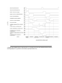
6 Fusing
The toner image transferred to the paper is fused under heat and pressure. Figure 2-6 shows an
electro-photographic process timing chart.
Copyright 1998, Okidata, Division of OKI America, Inc. All rights reserved. See the OKIDATA Business Partner
Exchange (BPX) for any updates to this material. (http://bpx.okidata.com)
Page: 16
Service Guide OKIPAGE 18/18n
Chapter 2 Operation Description
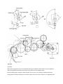
2.3.3 Process operation descriptions
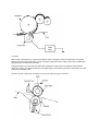
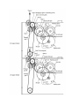
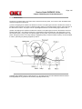
(1) Hopping
Hoppings from the first tray and the front feeder are effected by a single hopping motor in the mechanism shown
below.
Turning the Hopping motor in direction a (CW) drives the 1st Hopping Roller. Turning the Hopping motor in direction
b (CCW) drives the Front Hopping Roller. Gear C and Hopping roller built-in one way bearing, so that turning each of
these gears in reverse direction will not be transmitted to the corresponding roller.
(a) Hopping from the 1st Tray
1 Hopping
Rotating the Hopping Motor in direction a (CW) drives the 1st Hopping Roller and the Sub Roller then pick up a
sheet of paper in the 1st tray. The Main Motor is always driven in direction c (CCW) on printing. After the paper is fed
approx. 30mm from the tray, the Clutch (Feed) drives the Align Roller to advance the paper until the Inlet Sensor
turns on.
2 Aligning
After turning on the Inlet Sensor, the paper fed by a predetermined length and choked up to the wedge space formed
by the Registration Roller and the Pressure Roller to align the skew of the paper.
3 During the paper fed from the 1st tray, the built-in clutch of Gear C is idled and does not drive the Front Hopping
Roller.
4 Feeding
After aligning the paper, the Hopping Motor is turned off and stops hopping. Also the Clutch (Feed) is turned off and
the Align Roller idles freely. Then the Clutch (Registration) is turned on and the Registration Roller starts to feed the
paper. After the paper is fed, the 1st Hopping Roller idles freely by releasing built-in one way clutch, also the Sub
Roller idles freely by escaping the Planet Gear.
5 Printing starts after the paper turns off the Write Sensor.
(b) Hopping from the Front Feeder
1 Hopping
The Front Feeder Plate is normally locked at the lower position by the Release Lever activating the Micro Switch.
The top of the FF Cam which is attached to the end of the Front Hopping Shaft is normally located in the upper
position (0 to 30 degree : home position). Rotating the Hopping Motor in direction b (CCW) drives the Front Hopping
Shaft, the attached FF Cam and the Front Hopping Roller. When the FF Cam is rotated approx. 60 degrees, the
Release Lever is pushed and the Front Feeder Plate lifts up allowing the Front Hopping Roller to pick up a sheet of
paper. When the FF Cam is rotated approx. 180 degree, the Front Feeder Plate is pushed down and locked by the
Release Lever again. When the FF Cam is rotated approx. 275 degrees the paper is fed until the Inlet Sensor turns
off.
2 Aligning
After turning on the Inlet Sensor, the paper is fed a predetermined length and choked up to the wedge space formed
by the Registration Roller and the Pressure Roller to align the skew of the paper.
3 While the paper is fed from the Front Feeder Plate, the one way clutch of 1st Hopping Roller is idled and does not
drive the 1st Hopping Roller and the Sub Roller.
4 Feeding
After aligning the paper, the Hopping Motor is turned off and stops hopping. Then the Clutch (Registration) is turned
on and the Registration Roller starts to feed the paper. After the paper is fed, the Front Hopping Roller drives the
Front Hopping Shaft and the attached FF Cam with a small idle torque of the built-in one way clutch advancing to the
Release Lever. The one way clutch is slipped and the FF Cam is stopped at the upper position (home position). The
Front Hopping Roller idles until the paper clears the roller.
5 Printing starts after the paper turns off the Write Sensor.
(2) Feeding
After finishing hopping, the pulse motor dedicated for driving the registration roller rotates to drive the registration
roller. The registration roller advances the paper until it comes out of the registration roller.
When the leading edge of the paper causes the paper sensor to turn on, the printing is started synchronously.
Although Gear D is always rotating due to an all-time rotation of the main motor in direction c, the registration roller
would not rotate because the clutch (registration) is turned off. After completion of hopping, turn on the clutch
(registration) to drive the registration roller. The registration roller will drive the paper until the paper has passed.
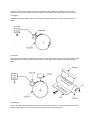
(3) Charging
Charging is effected by applying a DC minus voltage to the charge roller that is in contact with the image drum
surface.
(4) Exposure
Light emitted from the LED head radiates the image drum surface with negative charges. The surface potential of the
charged part of the image drum drops, thereby forming an electrostatic latent image associated with the image
signal.
(5) Developing
Toner is attracted to the electrostatic latent image on the image drum surface to convert it into a visible toner image.
Developing takes place at the contact between the image drum and the developing roller.
1 As the toner supply roller rotates while rubbing on the developing roller, a friction charge is generated between the
developing roller and the toner, allowing the toner to be attracted to the developing roller. (The developing roller
surface is charged positive and the toner, negative.)
2 The toner attracted to the developing roller is scraped off by the doctor blade, forming a thin coat of toner on the
developing roller surface.
3 Toner is attracted to the exposed part (low-potential part) of the image drum at the contact between the image
drum and the developing roller, making the electrostatic latent image visible.
(6) Transfer
The transfer roller is composed of conductive sponge material and is designed to make the image drum surface and
the paper closely into contact.
Paper is placed over the image drum surface, and a positive charge, opposite in polarity to the toner, is applied to
the paper from its reverse side.
The application of a high positive voltage from the power supply to the transfer roller causes the positive charge
induced to the transfer roller surface to be transferred to the paper at the contact between the transfer roller and the
paper. As a results, toner charged negative that is attracted to the image drum surface is transferred to the upper
side of the paper by the
positive charge on the lower side of the paper.
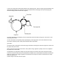
(7) Fusing
After the end of the transfer, the unfused toner image is fused on the paper under heat and pressure as it passes
between the heater roller and the back-up roller. The heater roller with a Teflon coating incorporates a 750W heater
(Halogen lamp), which heats the heat roller.
A thermistor which is in contact with the heater roller regulates the heater roller at a predetermined temperature
(about 180 ~ 200°C). A safety thermostat cuts off voltage supply to the heater by opening the thermostat in the event
of abnormal temperature rises.
The back-up roller is held under a pressure of 5 kg from the pressure spring at each side.
(8) Cleaning
After the end of the transfer, residual toner on the image drum is attracted to the cleaning roller temporarily by static
electricity to clean the image drum surface.
(9) Cleaning of rollers
The charge roller, transfer roller and cleaning roller are cleaned in the following cases:
l
l
l
In warming up at power-on time
In warming up after the cover is opened and closed
When the number of accumulated sheets is 10 or more and the printout operation ends
Changes in bias voltage applied to each roller move adhesive toner from the roller to the image drum and return it to
the developer.
Copyright 1998, Okidata, Division of OKI America, Inc. All rights reserved. See the OKIDATA Business Partner
Exchange (BPX) for any updates to this material. (http://bpx.okidata.com)
Page: 17
Service Guide OKIPAGE 18/18n
Chapter 2 Operation Description
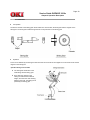
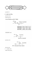
2.3.4 Revision of LED Head Illumination
An LED correcting head, which is capable of correcting the illumination of the LED for each dot, is being used in this
printer. LED illumination correction function of 16 steps is carried out by using an EEPROM which is installed in the
LSI that maintains the LED illumination correction values, and an LED correction drivers together as a pair.
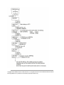
The LED correcting head consists of the correction control LSI , LED drivers , and an LED array.
The block diagram of the LED correcting head is shown below.
(1) Both sides wire-bonding head
In OKIPAGE 18/18n, the correction control of LED head is executed directly by the CPU.
The procedure is as follows
(i) LED head is set to the correction control read mode and all correction data stored in EEPROM within the
correction control LSI are read by CPU, and stored temporarily in the memory.
ii) Next LED head is set to the correction control direct mode and the correction data stored temporarily in the
memory is transferred directly to the LED driver.
(i) Read of correction data
(ii) Transfer of correction data to head driver correction data
(2) One side wire-bonding head
(i) LED head is set to the correction control read mode and all correction data stored in EEPROM within the
correction control LSI are read by CPU, and stored temporarily in the memory.
(ii) Next, LED head is set to the correction control direct mode and the correction data stored temporarily in the
memory is transferred directly to the LED driver.
(i) Read of correction data
(ii) Transfer of correction data to head driver correction data
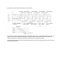
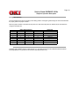
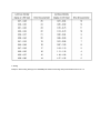
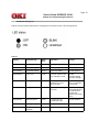
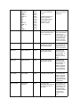
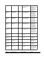
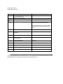
The LED driver corrects the LED illumination by controlling the LED current. The LED illumination can be set in 16
steps, with 7 steps in the direction of illumination increase in relation to the standard value, and 8 steps in the
direction of decrease. For this reason, the LED correction data is a 4-bit data for each dot.
The relationship between the LED correction data and LED current correction steps with the LED driver used in an
LED head is shown below.
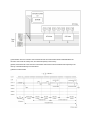
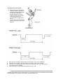
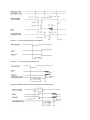
The printing operation timing chart is shown below.
The printing operation is carried out in normal mode. Under ordinary circumstances such as when the power is
turned on or when LOAD signal level is low, the normal mode is enabled. The printing operation is carried out in the
following sequence. First, the printing data DATA3 through DATA0 are stored, sequentially shifted, in the shift
registers of the LED drivers, by the
printing data synchronous clock, CLOCK. Then the printing data stored in shift registers are latched by the high level
pulse of LOAD. The latched printing data turns the LEDs on by STRB1-N through STRB4-N and actuates printing.
Copyright 1998, Okidata, Division of OKI America, Inc. All rights reserved. See the OKIDATA Business Partner
Exchange (BPX) for any updates to this material. (http://bpx.okidata.com)
Page: 18
Service Guide OKIPAGE 18/18n
Chapter 2 Operation Description
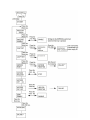
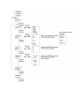
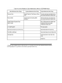
2.4 Paper Jam Detection
The paper jam detection function supervises the paper state at power-on time and during printing. In the
event that the following state occurs, this function interrupts the printing process. If any of the following
errors is present, recovery printing will be performed by removing the jammed paper (namely by opening
the upper cover, removing the jammed paper and closing the upper cover).
Error
Cause of Error
Paper input jam
l
l
Paper feed jam
l
l
Paper exit jam
l
l
Paper size error
l
At power-on time, the paper is placed at the inlet sensor.
After hopping operation is attempted three times, the leading edge
of the paper does not reach the inlet sensor.
At power-on time, the paper is placed at the paper sensor.
The leading edge of the paper does not reach the paper sensor
within a predetermined distance after the paper has reached the
inlet sensor.
l The trailing edge of the paper does not pass over the paper sensor
within a predetermined distance after the leading edge of the paper
has passed over the paper sensor.
l The leading edge of paper does not reach the outlet sensor within
a predetermined distance after the paper has reached the paper
sensor.
At power-on time, the paper is placed on the outlet sensor.
The paper does not pass over the outlet sensor within a
predetermined after the leading edge of the paper has reached the
outlet sensor.
l The paper size check with the manual feed specified considers the
reference size as free size.
The size of the paper is supervised by the inlet sensors 1. It is
detected that the paper does not pass over the inlet sensor 1 within
predetermined range of distance.
l The inlet sensor 2 detects that the size of the loaded paper is A4 or
larger, or smaller than A4. The detected paper size differs from the
paper size set by command or menu.
l The paper size check with the manual feed specified considers the
reference size as free size.
Copyright 1998, Okidata, Division of OKI America, Inc. All rights reserved. See the OKIDATA Business Partner
Exchange (BPX) for any updates to this material. (http://bpx.okidata.com)
Page: 19
Service Guide OKIPAGE 18/18n
Chapter 2 Operation Description
2.5 Cover Open
When the stacker cover is opened, the cover open microswitch on the Power Supply Unit (High voltage) is
turned off to cut the supply of +30V to the high voltage power supply circuit. As a result, all high-voltage
outputs are interrupted. At the same time, the CVOPN signal is sent to the control board to notify it of the
off state of the microswitch, and the Main board performs the cover open processing.
Copyright 1998, Okidata, Division of OKI America, Inc. All rights reserved. See the OKIDATA Business Partner
Exchange (BPX) for any updates to this material. (http://bpx.okidata.com)
Page: 20
Service Guide OKIPAGE 18/18n
Chapter 2 Operation Description
2.6 Toner Low Detection
l
Composition
The device consists of the stirring gear which rotates at a constant rate, the stirring bar and the magnet on the
stirring bar. The stirring bar rotates through the link on the protrusion in the stirring gear.
l
Operation
Toner Low is detected by monitoring the time interval of the encounter of the magnet set on the sensor lever and the
magnet on the stirring bar.
Operation during toner full state
l
The stirring bar rotates due to the
interlocking with the stirring gear.
l
Even when the magnet on the
stirring bar reaches the maximum
height, since the other side is being
dipped in the toner, the stirring bar is
pushed by the stirring gear.
Operating during toner low state
l
l
l
l
l
When the stirring bar reaches the
maximum height, since there is no
resistance provided by the toner on
the other side, it falls to the
minimum height due to its own
weight. Because of this, the time
interval during which it is in
encounter with the magnet of the
sensor
lever becomes long. By monitoring
this time interval, toner low can be
detected.
When the toner low state is detected 2 times consecutively, Toner Low is established.
When the toner full state is detected 2 times consecutively, Toner Low is canceled.
When there is no change with the toner sensor for 2 cycles (2.727 sec. x 2) or more, then the
Toner Sensor Alarm is activated.
The toner sensor is not monitored while the drum motor is in halt.
Copyright 1998, Okidata, Division of OKI America, Inc. All rights reserved. See the OKIDATA Business Partner
Exchange (BPX) for any updates to this material. (http://bpx.okidata.com)
Page: 21
Service Guide OKIPAGE 18/18n
Chapter 2 Operation Description
2.7 Stacker-full Detection
The sensor (interlocked with the lever) at the paper outlet to the stacker detects a stacker-full state (about 250
sheets) and stops printing of the ensuing pages.
Copyright 1998, Okidata, Division of OKI America, Inc. All rights reserved. See the OKIDATA Business Partner
Exchange (BPX) for any updates to this material. (http://bpx.okidata.com)
Page: 22
Service Guide OKIPAGE 18/18n
Chapter 2 Operation Description
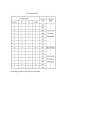
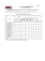
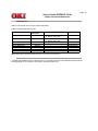
2.8 Page Size Detection
The four tab pieces are driven according to the setting position of the paper guide through the cam interlocked with
the paper guide of the paper cassette.
When the paper cassette is inserted into the printer, the state of the tab pieces is detected by the microswitch to
recognize the paper size.
SW1
0
0
0
1
1
1
1
1
State of Microswitches
SW2
SW3
1
1
0
1
0
1
1
0
1
0
1
1
1
0
0
0
Paper Size
SW4
1
1
1
0
1
1
0
1
Letter
Executive
A4
Legal 14
Legal 13
B5
A5
A6 (Not available)
Copyright 1998, Okidata, Division of OKI America, Inc. All rights reserved. See the OKIDATA Business Partner
Exchange (BPX) for any updates to this material. (http://bpx.okidata.com)
Page: 23
Service Guide OKIPAGE 18/18n
Chapter 3 Parts Replacement
Parts Replacements
This section explains the procedures for replacement of parts, assemblies, and units in the field. Only the removal
procedures are explained here. Reverse the procedure for the installation.
3.1 Precautions for Parts Replacement
3.2 Parts Layout
3.3. Replacing Parts
Copyright 1998, Okidata, Division of OKI America, Inc. All rights reserved. See the OKIDATA Business Partner
Exchange (BPX) for any updates to this material. (http://bpx.okidata.com)
Page: 24
Service Guide OKIPAGE 18/18n
Chapter 3 Parts Replacement
3.1 Precautions for Parts Replacement
(1) Be starting parts replacement, remove the AC cable and interface cable.
(a) Remove the Ac cable in the following procedure:
i) Turn off ("o") the power switch of the printer.
ii) Disconnect the AC inlet plug of the AC cable from the AC receptacle.
iii) Disconnect the AC cable and interface cable from the printer.
(b) Reconnect the printer in the following procedures:
i) Connect the AC cable and interface cable to the printer.
ii) Connect the AC inlet plug to the AC receptacle.
iii) Turn on ("I") the power switch of the printer.
(2) Do not try disassembly as long as the printer is operating normally.
(3) Do not remove unnecessary parts: try to keep disassembly to a minimum.
(4) Use specified service tools.
(5) When disassembling, follow the determined sequence. Otherwise, parts may be damaged.
(6) Since screws, collars and other small parts are likely to be lost, they should temporarily be attached to
the original positions.
(7) When handling ICs such as microprocessors, ROM and RAM, and circuit boards, do not wear gloves
that are likely to generate static electricity.
(8) Do not place printed circuit boards directly on the equipment or floor.
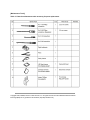
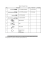
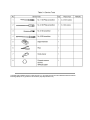
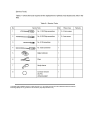
[Maintenance Tools]
Table 3-1 lists the maintenance tools necessary for parts replacement.
Copyright 1998, Okidata, Division of OKI America, Inc. All rights reserved. See the OKIDATA Business Partner
Exchange (BPX) for any updates to this material. (http://bpx.okidata.com)
Page: 25
Service Guide OKIPAGE 18/18n
Chapter 3 Parts Replacement
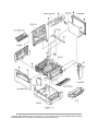
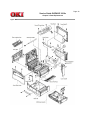
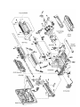
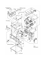
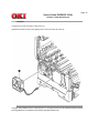
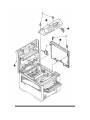
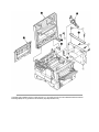
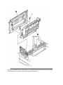
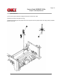
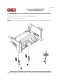
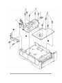
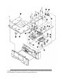
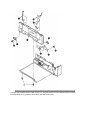
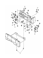
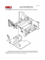
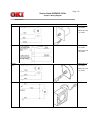
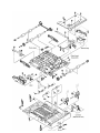
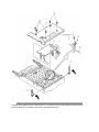
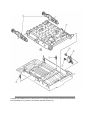
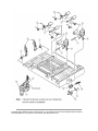
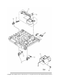
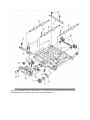
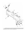
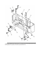
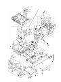
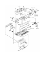
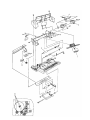
3.2 Parts Layout
This section explains the layout of main parts.
Figure 3-1
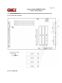
Figure 3-2
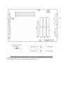
Figure 3-3
Copyright 1998, Okidata, Division of OKI America, Inc. All rights reserved. See the OKIDATA Business Partner
Exchange (BPX) for any updates to this material. (http://bpx.okidata.com)
Page: 26
Service Guide OKIPAGE 18/18n
Chapter 3 Parts Replacement
Figure 3-1
Copyright 1998, Okidata, Division of OKI America, Inc. All rights reserved. See the OKIDATA Business Partner
Exchange (BPX) for any updates to this material. (http://bpx.okidata.com)
Page: 27
Service Guide OKIPAGE 18/18n
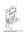
Chapter 3 Parts Replacement
Figure 3-2
Copyright 1998, Okidata, Division of OKI America, Inc. All rights reserved. See the OKIDATA Business Partner
Exchange (BPX) for any updates to this material. (http://bpx.okidata.com)
Page: 28
Service Guide OKIPAGE 18/18n
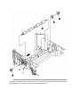
Chapter 3 Parts Replacement
Figure 3-3
Copyright 1998, Okidata, Division of OKI America, Inc. All rights reserved. See the OKIDATA Business Partner
Exchange (BPX) for any updates to this material. (http://bpx.okidata.com)
Page: 29
Service Guide OKIPAGE 18/18n
Chapter 3 Parts Replacement
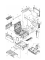
3.3 How to Change Parts
This section explains how to change parts and assemblies appearing in the disassembly diagram below.
3.3.1 Faceup Stacker Assy
3.3.2 Contact Assy
3.3.3 DC Fan Motor
3.3.4 OP Panel Assy
3.3.5 Board-FFF
3.3.6 Stacker Assy, Damper Arm, Cover Rear
3.3.7 Sensor Stacker Full
3.3.8 Cable cover (guide film)
3.3.9 Damper
3.3.10 Feeder Unit - Front
3.3.11 Roller Assy - Regist
3.3.12 Motor - Main
3.3.13 Guide Assy - Eject
3.3.14 Heat Assy
3.3.15 Roller feed (C)
3.3.16 Roller Assy - BK
3.3.17 Roller Assy - Feed
3.3.18 LED Head
3.3.19 Paper cassette, ROLLER Assy - Feed, ROLLER - Assy, Hopping
3.3.20 Frame Assy - Separation
3.3.21 Transfer Roller / TR Gear / TR Bearing
3.3.22 EP lock shaft
3.3.23 LEVER Assy - Out Sensor
3.3.24 Toner sensor lever
3.3.25 Paper sensor lever
3.3.26 Inlet sensor lever
3.3.27 Power supply unit
3.3.28 Lever - Paper end & Lever - Paper near end
3.3.29 Guide Assy - Cassette (L)
3.3.30 Guide Assy - Cassette (R)
Copyright 1998, Okidata, Division of OKI America, Inc. All rights reserved. See the OKIDATA Business Partner
Exchange (BPX) for any updates to this material. (http://bpx.okidata.com)
Page: 30
Service Guide OKIPAGE 18/18n
Chapter 3 Parts Replacement
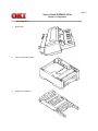
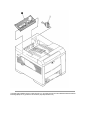
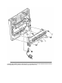
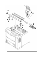
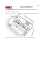
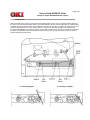
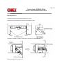
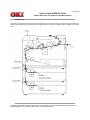
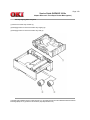
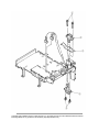
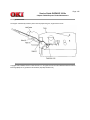
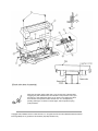
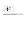
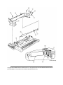
3.3.1 Face-up Stacker Assy
(1) Turn off the AC Power Switch and unplug the AC Power Cord from the outlet.
(2) Disconnect the Interface Cable (1).
(3) Open the face-up stacker assy (2), unhook the right and left projections, and then remove the face-up stacker
assy (2).
Copyright 1998, Okidata, Division of OKI America, Inc. All rights reserved. See the OKIDATA Business Partner
Exchange (BPX) for any updates to this material. (http://bpx.okidata.com)
Page: 31
Service Guide OKIPAGE 18/18n
Chapter 3 Parts Replacement
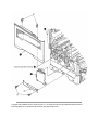
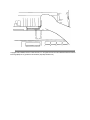
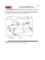
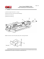
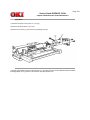
3.3.2 Contact Assy
(1) Open the stacker assy (1) and unscrew 2 screws (2) to remove the cover assy-side (L)(3).
(2) Unscrew 2 screws (4) and remove the plate (contact) (5) and contact Assy (6).
Note! Don't deform the electrode plates of the contact assy (6).
Copyright 1998, Okidata, Division of OKI America, Inc. All rights reserved. See the OKIDATA Business Partner
Exchange (BPX) for any updates to this material. (http://bpx.okidata.com)
Page: 32
Service Guide OKIPAGE 18/18n
Chapter 3 Parts Replacement
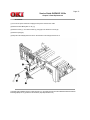
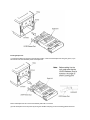
3.3.3 DC Fan Motor
(1) Remove the cover assy-side (L). [See 3.3.2 (1)]
(2) Remove the DC fan motor (1) by pulling out the connector of DC fan motor (1).
Copyright 1998, Okidata, Division of OKI America, Inc. All rights reserved. See the OKIDATA Business Partner
Exchange (BPX) for any updates to this material. (http://bpx.okidata.com)
Page: 33
Service Guide OKIPAGE 18/18n
Chapter 3 Parts Replacement
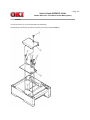
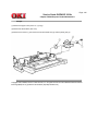
3.3.4 OP Panel Assy
(1) Disconnect the Interface cable (1).
(2) Open the stacker assy (2), unscrew 2 screws (3) and remove the cover assy-side (R) (4).
(3) Remove 2 screws (5) and flexible cable (6) to remove the operator panel assy (7).
Copyright 1998, Okidata, Division of OKI America, Inc. All rights reserved. See the OKIDATA Business Partner
Exchange (BPX) for any updates to this material. (http://bpx.okidata.com)
Page: 34
Service Guide OKIPAGE 18/18n
Chapter 3 Parts Replacement
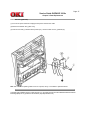
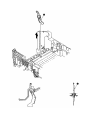
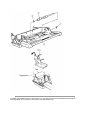
3.3.5 Board - FFF
(1) Remove the operator panel assy and cover assy-side (R). [See 3.3.4]
(2) Unscrew 2 screws (1) and remove the cover assy-corner (R) (2).
(3) Unscrew 16 screws (3) and remove plate-shield (4).
(4) Unscrew 3 screws (5) and 2 screws (6), unplug all the connectors (7) , and remove Board-FFF (8).
Copyright 1998, Okidata, Division of OKI America, Inc. All rights reserved. See the OKIDATA Business Partner
Exchange (BPX) for any updates to this material. (http://bpx.okidata.com)
Page: 35
Service Guide OKIPAGE 18/18n
Chapter 3 Parts Replacement
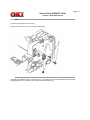
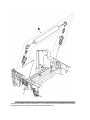
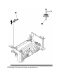
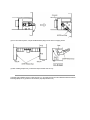
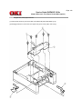
3.3.6 Stacker Assy, Damper Arm, Cover Rear
(1) Remove the face-up stacker assy. [See 3.3.1]
(2) Remove the cover assy-side (L). [See 3.3.2 (1)]
(3) Remove the OP panel assy. [See 3.3.4]
(4) Remove the Board-FFF. [See 3.3.5]
(5) Loosen 2 screws, unlock the latches from both sides and remove the rear cover (11).
(6) Unscrew 2 screws (1) and remove frame cover (2).
(7) Unscrew 3 screws (3) and remove the plate assy-side (R) (4).
(8) Remove the lever back up release (5) and unlock the engagement of the projection on the right side of gear at
the right side of the stacker cover.
(9) Remove a screw 6 and washer (7), and then remove the stacker assy (8). (At this time, the damper arm (9) can
also be detached simultaneously.)
Copyright 1998, Okidata, Division of OKI America, Inc. All rights reserved. See the OKIDATA Business Partner
Exchange (BPX) for any updates to this material. (http://bpx.okidata.com)
Page: 36
Service Guide OKIPAGE 18/18n
Chapter 3 Parts Replacement
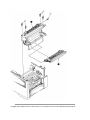
3.3.7 Sensor Stacker Full
(1) Turn the AC power switch off. Unplug the AC power cord from the outlet.
(2) Remove the Stacker assy. [See 3.3.6]
(3) Remove four screws (1). Remove stacker mount 2 by releasing the tabs at position (2A) .
(4) Remove Sensor stacker full (3) by spreading the plastic tabs on each side of sensor Assy (3) and lifting switch
from cover.
Copyright 1998, Okidata, Division of OKI America, Inc. All rights reserved. See the OKIDATA Business Partner
Exchange (BPX) for any updates to this material. (http://bpx.okidata.com)
Page: 37
Service Guide OKIPAGE 18/18n
Chapter 3 Parts Replacement
3.3.8 Cable cover (guide film)
(1) Turn the AC power switch off. Unplug the AC power cord from the outlet.
(2) Remove the stacker Assy. [See 3.3.6]
(3) Unscrew 2 screws (1) release tabs at portion (1A) . Remove cable cover 2, guide film (3).
Note: Use care when replacing cable cover. Do not pitch, crimp, or cut cables or protective sheet.
Copyright 1998, Okidata, Division of OKI America, Inc. All rights reserved. See the OKIDATA Business Partner
Exchange (BPX) for any updates to this material. (http://bpx.okidata.com)
Page: 38
Service Guide OKIPAGE 18/18n
Chapter 3 Parts Replacement
3.3.9 Damper
(1) Remove the damper arm. [See 3.3.6]
(2) Unscrew 2 screws (1) and remove the two dampers (2).
Copyright 1998, Okidata, Division of OKI America, Inc. All rights reserved. See the OKIDATA Business Partner
Exchange (BPX) for any updates to this material. (http://bpx.okidata.com)
Page: 39
Service Guide OKIPAGE 18/18n
Chapter 3 Parts Replacement
3.3.10 Feeder Unit - Front
(1) Open the manual feed assy (1) and release both right and left parts by pulling out the engagements on the lower
part.
(2) Stand the manual feed assy (1) on end and unhook the engagements with both right and left manual feed hopper
stays.
(3) Remove the OP panel assy. [See 3.3.4]
(4) Unscrew 5 screws (2) and remove the feeder unit-front (3).
Copyright 1998, Okidata, Division of OKI America, Inc. All rights reserved. See the OKIDATA Business Partner
Exchange (BPX) for any updates to this material. (http://bpx.okidata.com)
Page: 40
Service Guide OKIPAGE 18/18n
Chapter 3 Parts Replacement
3.3.11 Roller Assy - Regist
(1) Remove the feeder unit-front. [See 3.3.10]
(2) Remove an E-ring (3), gear assy-clutch (4), and four screws (1) in this order, and lift out the roller
assy-registration (2).
Copyright 1998, Okidata, Division of OKI America, Inc. All rights reserved. See the OKIDATA Business Partner
Exchange (BPX) for any updates to this material. (http://bpx.okidata.com)
Page: 41
Service Guide OKIPAGE 18/18n
Chapter 3 Parts Replacement
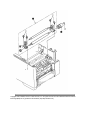
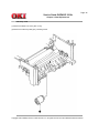
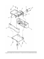
3.3.12 Motor - Main
(1) Remove the stacker assy. [See 3.3.6]
(2) Remove the feeder unit-front. [See 3.3.10] (At this point, the manual feed assy does not have to be removed.)
(3) Remove the DC fan motor. [See 3.3.3]
(4) Remove the contact assy. [See 3.3.2]
(5) Remove the plate-FG (F) (1).
(6) Remove the TR gear (2) and roller transfer (3). (Use Holder-TR Eject (16) for the removal.)
(7) Unscrew 7 screws (4) and remove the main frame (5).
(8) Unlock latches at two points of the lever back up release 6 and pull it out in right direction.
(9) Unhook the EP lock spring (7) and remove the EP lock lever (8).
(10) Take off the E ring (9) and remove the plate-FG (1st ) (10) and gear assy-clutch (11).
(11) Unlock 2 latches to remove the motor assy-main (12) and idle gear (13).
(12) Unscrew 2 screws (14) and remove the motor -main (15) .
Copyright 1998, Okidata, Division of OKI America, Inc. All rights reserved. See the OKIDATA Business Partner
Exchange (BPX) for any updates to this material. (http://bpx.okidata.com)
Page: 42
Service Guide OKIPAGE 18/18n
Chapter 3 Parts Replacement
3.3.13 Guide Assy - Eject
(1) Remove the lever back up release. [See 3.3.12(8)] (But the roller transfer/feeder unit front/plate-FG do not have
to be removed)
(2) Loosen 2 screws (1), unlock both side latches and remove the cover rear (2). [See 3.3.6(5)]
(3) Unlock the latches on both sides of the guide assy-eject (3) and lift it out.
Copyright 1998, Okidata, Division of OKI America, Inc. All rights reserved. See the OKIDATA Business Partner
Exchange (BPX) for any updates to this material. (http://bpx.okidata.com)
Page: 43
Service Guide OKIPAGE 18/18n
Chapter 3 Parts Replacement
3.3.14 Heat Assy
(1) Remove the cover assy-side (L). [See 3.3.2 (1)]
(2) Unplug the connectors (1), (2).
(3) Unscrew 4 screws (3) and remove the heat assy (4) in the direction of the arrow by lifting the right side first.
Note !
l
As the heat assy (4) remains at high temperature soon after the power is turned off, start the work after it cools
off sufficiently.
l
Carry out a reset of the counter after the replacement. (See Section 4.2)
Copyright 1998, Okidata, Division of OKI America, Inc. All rights reserved. See the OKIDATA Business Partner
Exchange (BPX) for any updates to this material. (http://bpx.okidata.com)
Page: 44
Service Guide OKIPAGE 18/18n
Chapter 3 Parts Replacement
3.3.15 Roller feed (C)
(1) Remove the guide assy-eject. (See 3.3.13)
(But roller transfer/feeder unit-front/plate-FG(F) do not have to be removed)
(2) Remove the gear roller (C) (1) and bushing (2), bend (a) part of the plate-FG (BK) (3). Take off the carrier bearing
(4) and remove the roller feed (c) (5) in the direction of the arrow.
Note ! Be careful not to deform (a) part of the plate-FG (BK) (3).
Copyright 1998, Okidata, Division of OKI America, Inc. All rights reserved. See the OKIDATA Business Partner
Exchange (BPX) for any updates to this material. (http://bpx.okidata.com)
Page: 45
Service Guide OKIPAGE 18/18n
Chapter 3 Parts Replacement
3.3.16 Roller Assy - BK
(1) Remove the heat Assy. [See 3.3.14]
(2) Remove the lever back up release. [See 3.3.12 (8)]
(3) Unlock the engagement with the plate-FG (BK) (1) and lift out the roller heat assy (2).
Copyright 1998, Okidata, Division of OKI America, Inc. All rights reserved. See the OKIDATA Business Partner
Exchange (BPX) for any updates to this material. (http://bpx.okidata.com)
Page: 46
Service Guide OKIPAGE 18/18n
Chapter 3 Parts Replacement
3.3.17 Roller Assy - Feed
(1) Remove the feeder unit -front. [See 3.3.10]
(2) Remove the roller assy-feed (1) by unlocking a latch.
Copyright 1998, Okidata, Division of OKI America, Inc. All rights reserved. See the OKIDATA Business Partner
Exchange (BPX) for any updates to this material. (http://bpx.okidata.com)
Page: 47
Service Guide OKIPAGE 18/18n
Chapter 3 Parts Replacement
3.3.18 LED Head
(1) Remove the stacker assy (1). [See 3.3.6]
(2) Unplug the PC connector (2) and 2 LED cables (3) from the LED head (4).
(3) Open the hooks of the cover stacker 1 in the direction of the arrow and remove the LED head (4).
(4) Pull out the head spring (5) from the post.
Note: Don't remove two LED cable (3) from the PC connector (2).
Copyright 1998, Okidata, Division of OKI America, Inc. All rights reserved. See the OKIDATA Business Partner
Exchange (BPX) for any updates to this material. (http://bpx.okidata.com)
Page: 48
Service Guide OKIPAGE 18/18n
Chapter 3 Parts Replacement
3.3.19 Paper cassette, ROLLER Assy - Feed, ROLLER Assy - Hopping
(1) Pull out the case assy-cassette (1) from the printer.
(2) Remove the ROLLER Assy-Feed (2) and remove the ROLLER Assy-Hopping (3).
Copyright 1998, Okidata, Division of OKI America, Inc. All rights reserved. See the OKIDATA Business Partner
Exchange (BPX) for any updates to this material. (http://bpx.okidata.com)
Page: 49
Service Guide OKIPAGE 18/18n
Chapter 3 Parts Replacement
3.3.20 Frame Assy - Separation
(1) Turn the AC power switch off. Unplug the AC power cord from the outlet.
(2) Pull out the case Assy-Cassette (1) from the printer. [See 3.3.19(1)]
(3) Release two locks and remove frame assy-separation (2). (At this time, coil spring 3 is also removed. Be careful
not to lose this spring.)
Copyright 1998, Okidata, Division of OKI America, Inc. All rights reserved. See the OKIDATA Business Partner
Exchange (BPX) for any updates to this material. (http://bpx.okidata.com)
Page: 50
Service Guide OKIPAGE 18/18n
Chapter 3 Parts Replacement
3.3.21 Transfer Roller / TR Gear / TR Bearing
(1) Open the stacker cover .
(2) Unlock the lock by lifting the TR gear (1) to remove the TR gear (1) and roller transfer (2). (Use the Holder-TR
Eject (5) for the removal.)
Note ! Don't place the removed roller transfer directly on the desk and so on. When placing it, lay a paper and the
like under it.
(3) Remove right and left bearings (3) from the frame-main by sliding them inside while pushing them. At the same
time, remove the 2 transfer springs (4).
Copyright 1998, Okidata, Division of OKI America, Inc. All rights reserved. See the OKIDATA Business Partner
Exchange (BPX) for any updates to this material. (http://bpx.okidata.com)
Page: 51
Service Guide OKIPAGE 18/18n
Chapter 3 Parts Replacement
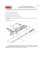
3.3.22 EP lock shaft
(1) Turn the AC power switch off. Unplug the AC power cord from the outlet.
(2) Remove Frame-Main [See 3.3.12 (7)].
(3) Remove screw (1). Turn EP lock lever (L) Assy (2) in the direction of arrow (A) .
(4) Remove spring (3).
(5) Drop EP lock shaft (4) down and turn in the direction of arrows (B) and remove it.
Copyright 1998, Okidata, Division of OKI America, Inc. All rights reserved. See the OKIDATA Business Partner
Exchange (BPX) for any updates to this material. (http://bpx.okidata.com)
Page: 52
Service Guide OKIPAGE 18/18n
Chapter 3 Parts Replacement
3.3.23 LEVER Assy - Out Sensor
(1) Turn the AC power switch off. Unplug the AC power cord from the outlet.
(2) Remove the frame main [See 3.3.12(7)]
(3) Press the clamp part of LEVER Assy- Out Sensor (1). Remove the LEVER Assy-Out Sensor (1) by pushing it
upward from the lower side.
Copyright 1998, Okidata, Division of OKI America, Inc. All rights reserved. See the OKIDATA Business Partner
Exchange (BPX) for any updates to this material. (http://bpx.okidata.com)
Page: 53
Service Guide OKIPAGE 18/18n
Chapter 3 Parts Replacement
3.3.24 Toner sensor lever
(1) Turn the AC power switch off. Unplug the AC power cord from the outlet.
(2) Remove the frame main [See 3.3.12(7)]
(3) Squeeze the clamp part of toner sensor lever (1) and remove the toner sensor lever (1) by pushing it upward from
the lower side.
Copyright 1998, Okidata, Division of OKI America, Inc. All rights reserved. See the OKIDATA Business Partner
Exchange (BPX) for any updates to this material. (http://bpx.okidata.com)
Page: 54
Service Guide OKIPAGE 18/18n
Chapter 3 Parts Replacement
3.3.25 Paper sensor lever
(1) Turn the AC power switch off. Unplug the AC power cord from the outlet.
(2) Remove the frame main [See 3.3.12(7)]
(3) Squeeze the clamp part of the paper sensor lever (1) and remove the paper sensor lever (1) by pushing it upward
from the lower side.
Copyright 1998, Okidata, Division of OKI America, Inc. All rights reserved. See the OKIDATA Business Partner
Exchange (BPX) for any updates to this material. (http://bpx.okidata.com)
Page: 55
Service Guide OKIPAGE 18/18n
Chapter 3 Parts Replacement
3.3.26 Inlet sensor lever
(1) Turn the AC power switch off. Unplug the AC power cord from the outlet.
(2) Remove the frame main [See 3.3.12(7)]
(3) Squeeze the clamp part of two inlet sensor levers (1). Remove the inlet sensor levers (1) by pushing them
downward.
Copyright 1998, Okidata, Division of OKI America, Inc. All rights reserved. See the OKIDATA Business Partner
Exchange (BPX) for any updates to this material. (http://bpx.okidata.com)
Page: 56
Service Guide OKIPAGE 18/18n
Chapter 3 Parts Replacement
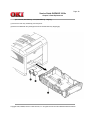
3.3.27 Power supply unit
(1) Turn the AC power switch off. Unplug the AC power cord from the outlet.
(2) Remove the frame main [See 3.3.12(7)]
(3) Unscrew 2 screws (1) and remove the BRACKET-AC (2).
(4) Unscrew 10 screws (3) and remove the connector 6 remove the Power supply unit [AC-DC (120/230V)] (4) and
Power supply unit (High voltage) (5).
Copyright 1998, Okidata, Division of OKI America, Inc. All rights reserved. See the OKIDATA Business Partner
Exchange (BPX) for any updates to this material. (http://bpx.okidata.com)
Page: 57
Service Guide OKIPAGE 18/18n
Chapter 3 Parts Replacement
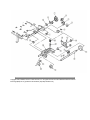
3.3.28 Lever-Paper end & Lever-Paper near end
(1) Turn the AC power switch off. Unplug the AC power cord from the outlet.
(2) Remove the frame main [See 3.3.12(7)]
(3) Remove screw (1) and then remove the PLATE-Base (2).
(4) Remove two Spacer-Cord (KGPS-5RF (3) and then remove FILM-Insulation (4).
(5) Remove four screws (5) and then remove the FRAME ASS-Hopping (6).
(6) Remove the GEAR-Z58 (9) and GEAR-Z42 (8). (At this time, the ADF Bearing (10) can also be detached
simultaneously.)
(7) Remove the GEAR-Z38 (14), ADF Bearing (15), ROLLER-Guide (16) and SHAFT Hopping (17) and Bracket-Sub
roller (28). (At this time, the Lock Pin (18) can also be detached simultaneously.)
(8) Remove two screws (7) and then remove the SPRING-Release (11) and then remove the LEVER-Sub roller (12)
and PLATE-Hopping (13).
(9) Remove the GEAR-Planet(Z28) (19), Plate-Planet (20), BRACKET-Spring (Sub) (21) and SPRING-Sub ROLLER
(22).
(10) Press the clamp part of Lever-Paper end (23) and Lever-Paper near end (24). Remove the Lever-Paper end (23)
and Lever-Paper near end (24) by pushing it upward from the FRAME Hopping (28).
(11) Remove the Connection Cord-Wire (25) and TR-23-11-14 R CORE (26) together.
(12) Remove two Photo Sensor (27).
Copyright 1998, Okidata, Division of OKI America, Inc. All rights reserved. See the OKIDATA Business Partner
Exchange (BPX) for any updates to this material. (http://bpx.okidata.com)
Page: 58
Service Guide OKIPAGE 18/18n
Chapter 3 Parts Replacement
3.3.29 Guide Assy - Cassette (L)
(1) Turn the AC power switch off. Unplug the AC power cord from the outlet.
(2) Remove Frame Main [See 3.3.12(7)]
(3) Remove PLATE-Base and FRAME Assy Hopping [See 3.3.28 (5)]
(4) Unscrew two screw (1) and then remove Guide Assy-Cassette (L) (2).
(5) Remove SPRING-Sheet (3) and then remove LINK-Sheet (4) and pull block (5). (Pay attention the direction of
hook of SPRING-Sheet (3).)
(6) Remove spring (6) and then remove cassette stopper (7).
(7) Remove screw (8) from LINK-Sheet (4) and then remove link support (9) and Roller-link (10).
(8) Remove Earth Plate L (11) and Plate-Earth (link) (12).
Copyright 1998, Okidata, Division of OKI America, Inc. All rights reserved. See the OKIDATA Business Partner
Exchange (BPX) for any updates to this material. (http://bpx.okidata.com)
Page: 59
Service Guide OKIPAGE 18/18n
Chapter 3 Parts Replacement
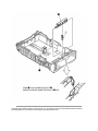
3.3.30 Guide Assy - Cassette (R)
(1) Turn the AC power switch off. Unplug the AC power cord from the outlet.
(2) Remove Frame Main [See 3.3.12(7)]
(3) Remove PLATE-Base and FRAME Assy Hopping [See 3.3.28 (5)]
(4) Unscrew two screw (1) and then remove Guide Assy-Cassette (R) (2).
(5) Remove SPRING-Sheet (3) and then remove LINK Sheet (4) and pull block (5). (Pay attention the direction of
hook of SPRING-Sheet (3).)
(6) Remove spring (6) and then remove cassette stopper (7).
(7) Remove screw 8 from LINK-Sheet (4) and then remove link support (9) and Roller-link (10).
(8) Unscrew two screws (11) and remove the Square shaped connector (176496-1) (12) and Nylon Connector Cord
(13) and TR-23-11-R CORE (14).
(9) Unscrew two screws (15) and remove the two Plate Earth (Bottom) (16).
(10) Unscrew two screws (17) and remove the Square shaped connector (5-176496-1) (18) and Connection Cord
Wire (19) and TR-23-11-R CORE (20).
(11) Unscrew a screw (21) and remove the Detector spring (22).
(12) Unscrew a screw (23) and remove the Board PXC (24).
Copyright 1998, Okidata, Division of OKI America, Inc. All rights reserved. See the OKIDATA Business Partner
Exchange (BPX) for any updates to this material. (http://bpx.okidata.com)
Page: 60
Service Guide OKIPAGE 18/18n
Chapter 4 Adjustment
4.0 Adjustment
This chapter explains the adjustment necessary when replacing a part. Adjustment is made by changing a parameter
value set in EEPROM on the controller PCB. The parameters are set with key presses from the operator panel. This
printer has three maintenance modes used to reset page counts when replacing a part, fine tune, troubleshoot and
diagnose.
Copyright 1998, Okidata, Division of OKI America, Inc. All rights reserved. See the OKIDATA Business Partner
Exchange (BPX) for any updates to this material. (http://bpx.okidata.com)
Page: 61
Service Guide OKIPAGE 18/18n
Chapter 4 Adjustment
4.1 Maintenance Modes and Functions
l
User maintenance mode
To enter the user maintenance mode, turn on the POWER switch while pressing the MENU key.
[Function]
There are 13 functions as follows.
l
l
l
l
l
l
l
l
l
l
l
l
l
l
Menu reset
Y adjust
Hex dump
Duplex Adjust
Drum counter reset
Select paper source command parameter
Resource Save (Second, Third, Front Tray)
Receive Buffer Size
Page placement
Operator panel menu disable
Setting
X adjust
Cleaning cycle
System maintenance mode
Note: This mode is used only by service personnel and should not be released to the end-user. To enter the system
maintenance mode, turn on the POWER switch while pressing the RECOVER key.
[Function]
There are 8 functions as follows.
l
l
l
l
l
l
l
l
l
l
Page count display
Page count printing enable/disable
Rolling ASCII continuos printing
RS232C LOOP TEST
EEPROM reset
HSP ERROR recovery
HSP ERROR count display
HSP ERROR count reset
SIDM enable/disable
Engine maintenance mode
Note: This mode is used only by service personnel and should not be released to the end-user.
To enter the engine maintenance mode, turn on the POWER switch while pressing the
FORM FEED key and ENTER key.
[Function]
There are 19 functions as follows.
l
l
l
l
l
l
l
l
l
l
l
l
l
l
l
l
l
l
l
Head type setting
Head drive time setting.
Head drive time setting at Auto head type
Head strobe time at 600 x 1200 dpi
Printing start position setting
Drum counter total display
Drum count display
Setting of standard paper feed length
Setting of front feeder paper feed length
Setting of second tray paper feed length
Selection of second tray feeder download table
Setting of third tray paper feed length
Selection of third tray feed download table
Setting of Multi-purpose feeder paper feed length
Selection of Multi-purpose feeder download table
Setting of duplex feed length
Fuser count indication
Fuser count reset
Engine reset
Copyright 1998, Okidata, Division of OKI America, Inc. All rights reserved. See the OKIDATA Business Partner
Exchange (BPX) for any updates to this material. (http://bpx.okidata.com)
Page: 62
Service Guide OKIPAGE 18/18n
Chapter 4 Adjustment
4.1.1 User maintenance mode
l
To enter the user maintenance mode, turn the power supply ON while pressing the Menu key.
l
This mode uses the menu for function selection.
l
The user maintenance mode provides the following functions:
(1) Menu reset
l
All settings for Menu level-1 are reset to the factory default values. The menus for all executable emulations
including options are reset to the factory default values.
l
The operation mode starts automatically upon completion of resetting.
(2) Hex dump
l
The data received from the host is dumped in hexadecimal notation to the printer.
l
Printing is activated automatically when the received data exceeds one page. If the received data is less than
one page, printing can be activated manually be pressing the Form Feed key after selecting the OFF LINE
mode by pressing the ON-LINE key. (Automatic activation of printing even when the received data is less than
one page by selecting the Auto Eject function on the menu.)
l
To exit from this mode, turn the power OFF.
(3) Drum counter reset
l
This function resets the drum life data when the user replaces the image drum unit.
l
The operation mode starts automatically upon completion of resetting.
(4) Resource Save
l
Set the storage area size of resource to be stored between PCL and Postscript.
(5) Receive Buffer Size
l
Set the receive buffer.
(6) Operator panel menu disable
l
This function is for enabling and disabling the operator panel menu functions (Menu 1, Menu 2, Tray Select,
Copies and Paper Size).
(7) X ADJUST
l
This function is used to adjust the printing start position within the range of ±2 mm in 0.25 mm steps in the X
direction.
(8) Y ADJUST
l
This function is capable to adjust the printing start position within the range of ±2 mm in 0.25 mm steps in the Y
direction.
(9) Duplex adjust
l
The function which performs a correction in Y direction towards the sheet supplied from the tray in double-sided
printing.
(10) Select paper source command parameter (Second tray)
l
The function which sets the parameter selecting the second tray by paper source command (ESC & N # H) on
PCL. (11) Select paper source command parameter (Third tray)
l
The function which sets the parameter selecting the third tray by paper source command (ESC & N # H) on
PCL.
(11) Select paper source command paramter (Third tray)
l
The function which sets the parameter selecting the third tray by paper source command (ESC & l # H) on PCL.
(12) Select paper source command parameter (Front tray)
l
The function which sets the parameter selecting the front tray by paper source command (ESC & N # H) on
PCL.
(13) Page placement
l
The function which aligns a printing image to the right.
(14) SETTING
l
This function is used to adjust to improve print quality.
-2 } Rough/thick paper, Low temperature/humidity and/or blotchy faded print appeared.
-1 } Rough/thick paper, Low temperature/humidity and/or blotchy faded print appeared.
0 } Normal media/environmental conditions.
+1 } Rough papers, high temperature/humidity and/or snowy print of high density pattern.
+2 } Rough papers, high temperature/humidity and/or snowy print of high density pattern.
(15) Cleaning cycle
l
Set the page interval to perform Cleaning Sequence.
When stains build up especially in using rough papers. Change the cleaning cycle. The shorter the cycle is set, the
less the stains become.
Normal : Each 20th page (default)
Middle : Each 10th page
High : Each 3rd page
User maintenance mode menu system
Copyright 1998, Okidata, Division of OKI America, Inc. All rights reserved. See the OKIDATA Business Partner
Exchange (BPX) for any updates to this material. (http://bpx.okidata.com)
Page: 63
Service Guide OKIPAGE 18/18n
Chapter 4 Adjustment
4.1.2 System maintenance mode
l
The system maintenance mode is set when the power is turned ON while pressing the Recover key.
l
This mode adopts the menu for function selection.
l
The system maintenance mode is provided with the following functions:
(1) Page count display
l
The total number of pages counted at the engine is displayed on the LCD.
(2) Page count printing enable/disable
l
This function selects whether to include (enable) or exclude (disable) the total number of printed pages counted
at the engine at the time of menu printing.
(3) Rolling ASCII continuous printing
l
The rolling ASCII pattern is printed continuously for various engine tests.
l
Press the ON-LINE key to cancel this mode.
(4) RS232C LOOP TEST
l
Performs a loop test of RS 232C.
(5) EEPROM reset
l
All EEPROM areas including Menu level-2 to the factory default values.
l
The following items are excluded
* Head drive time setting
* Fine adjustment of printing start position
* Standard tray paper feed amount setting
l
Transition to the operation mode occurs upon completion of resetting.
l
Press the Menu key to update each category. The operation returns to the first category after updating the last
category.
(6) HSP ERROR recovery
l
Select HSP ERROR recovery function either recover or stop.
(7) HSP ERROR count
l
Display total HSP ERROR count.
(8) HSP ERROR count reset
l
Reset the HSP ERROR counter.
(9) SIDM enable/disable
l
If it's selected disable, cannot select SIDM emulations by Menu.
System maintenance mode menu system
Copyright 1998, Okidata, Division of OKI America, Inc. All rights reserved. See the OKIDATA Business Partner
Exchange (BPX) for any updates to this material. (http://bpx.okidata.com)
Page: 64
Service Guide OKIPAGE 18/18n
Chapter 4 Adjustment
4.1.3 Engine maintenance mode
l
The engine maintenance mode is activated when the power is turned ON while pressing the Form Feed key and
Enter key.
l
This mode adopts the menu for function selection.
l
The method for exit from this mode depends on the setting.
l
The engine maintenance mode is provided with the following functions:
(1) Head type setting select LED Head type
l
Sets the select LED head type.
(2) Head drive time setting
l
Sets the drive time of the LED head.
(3) Head drive time setting at auto head type
l
This function sets head drive time, when " HEADTYPE= AUTO" is selected.
(4) Head strobe time at 600 x 1200 dpi
l
This function sets head strobe time at 600 x 1200 dpi.
(5) Printing start position setting
l
Sets the printing start position.
(6) Drum count total display
l
Displays on the LCD the total number of drum revolutions in the unit counted at the engine.
(7) Drum count display
l
Displays on the LCD the total number of EP drum revolutions counted at the engine.
(8) Setting of standard tray paper feed length
l
This function sets the paper feed length of standard tray paper.
(9) Setting of front feeder paper feed length
l
This function sets the paper feed length of the front feeder.
(10) Setting of High Capacity Second Paper Feeder paper feed length
l
This function sets the paper feed length of the High Capacity Second Paper Feeder.
(11) Selection of High Capacity Second Paper Feeder download table
l
This function selects the download table for the High Capacity Second Paper Feeder.
(12) Setting of High Capacity Third Paper Feeder paper feed length
l
This function sets the paper feed length of the High capacity Third paper feeder.
(13) Selection of High Capacity Third paper feeder download table
l
This function selects the download table for the High capacity third paper feeder.
(14) Setting of Multi Feeder paper feed length
l
This function sets the paper feed length of the Multi Feeder.
(15) Selection of Multi Feeder download table
l
This function selects the download table for the Multi Feeder.
(16) Setting of duplex feed length
l
This function sets the paper feed length of the duplex.
(17) Fuser count display
l
Displays on the LCD the total number of printed pages counted at the engine.
(18) Fuser count reset
l
When the fuser unit is replaced, the maintenance person uses this fuser count reset function to reset the fuser
lifetime.
l
After the fuser counter is reset, the engine enters into the operation mode automatically
(19) Engine reset
l
All EEPROM areas used by the engine are reset to the factory default values.
l
The following items are excluded:
* Menu level-1
* Menu level-2
* Operator panel menu disable/enable
* Page print disable/enable
l
Transition to the operation mode occurs upon completion of resetting.
Note: Do not change the default value of (1)~ (5), (8)~ (16) they are the parameter for adjusting in the factory.
l
Engine maintenance mode menu system
Copyright 1998, Okidata, Division of OKI America, Inc. All rights reserved. See the OKIDATA Business Partner
Exchange (BPX) for any updates to this material. (http://bpx.okidata.com)
Page: 65
Service Guide OKIPAGE 18/18n
Chapter 4 Adjustment
4.1.4 EEPROM initialization
The corresponding area of the EEPROM is initialized for each event as shown Table 4-1 and Table 4-2.
Copyright 1998, Okidata, Division of OKI America, Inc. All rights reserved. See the OKIDATA Business Partner
Exchange (BPX) for any updates to this material. (http://bpx.okidata.com)
Page: 66
Service Guide OKIPAGE 18/18n
Chapter 4 Adjustment
4.2 Adjustment When Replacing a Part
Adjustment necessary when replacing one of the following parts.
Parts to be Replaced
Adjustment
Image Drum Unit
Reset the drum counter. (Refer to User's Manual)
Fuser Unit
Reset the fuser counter. (Refer to Chapter 4.2.1)
4.2.1 Setting LED Head Drive Time
4.2.2 Destination Setting
4.2.3 Setting of ED had drive time
Copyright 1998, Okidata, Division of OKI America, Inc. All rights reserved. See the OKIDATA Business Partner
Exchange (BPX) for any updates to this material. (http://bpx.okidata.com)
Page: 67
Service Guide OKIPAGE 18/18n
Chapter 4 Adjustment
4.2.1 Setting LED Head Drive Time
(1) The fuser counter can be reset in the engine maintenance mode.
(2) Resetting method
Copyright 1998, Okidata, Division of OKI America, Inc. All rights reserved. See the OKIDATA Business Partner
Exchange (BPX) for any updates to this material. (http://bpx.okidata.com)
Page: 68
Service Guide OKIPAGE 18/18n
Chapter 4 Adjustment
4.2.2 Destination setting
The desired destination can be set by turning the power on while depressing two keys corresponding to the
destination according to the following table.
Destination
Keys to be depressed
ODA
MENU,
This function shall not be open for users.
Copyright 1998, Okidata, Division of OKI America, Inc. All rights reserved. See the OKIDATA Business Partner
Exchange (BPX) for any updates to this material. (http://bpx.okidata.com)
Page: 69
Service Guide OKIPAGE 18/18n
Chapter 4 Adjustment
4.2.3 Setting of LED head drive time
As the OKIPAGE18/18n automatically judges head type and head drive time, there is no need for changing any
setting in replacing LED head. But individual setting can be changed by ENGINE Maintenance menu as before. The
procedure in such case shown below.
l
Luminous intensity marking label
l
Setting of LED head drive time
Drive time of the LED head is to set parameter of drive time setting values corresponding to the luminous intensity
displays marked on the LED head to EEPROM.
a. Corresponding table of luminous energy display and drive time parameter
b. Setting
Example : When setting head type to TYPE3WB( both-sided wire-bonding head) and head drive time to No. 14.
Copyright 1998, Okidata, Division of OKI America, Inc. All rights reserved. See the OKIDATA Business Partner
Exchange (BPX) for any updates to this material. (http://bpx.okidata.com)
Page: 70
Service Guide OKIPAGE 18/18n
Chapter 5 Periodical Maintenance
5.1 Periodic Maintenance
Table 5-1 lists the part and unit to be replaced periodically.
Table 5-1 Routine Replacement Parts
Part Name
Condition for
replacement
Toner cartridge
5,000
Image drum unit
30,000
Heat Assy
Transfer Roller
Back up Roller Assy
Feed Roller Assy
Hopping Roller Assy
Separation Frame Assy
200,000
200,000
200,000
200,000
200,000
200,000
Cleaning
l
l
l
l
LED head.
Regist. Paper dust.
LED head.
Regist. Paper dust.
Remarks
Consumables
Consumables
Maintenance Kit
Maintenance Kit
Maintenance Kit
Maintenance Kit
Maintenance Kit
Maintenance Kit
[Note: Maintenance Kit shall be replenished by users calling to serviceman.]
Copyright 1998, Okidata, Division of OKI America, Inc. All rights reserved. See the OKIDATA Business Partner
Exchange (BPX) for any updates to this material. (http://bpx.okidata.com)
Page: 71
Service Guide OKIPAGE 18/18n
Chapter 5 Periodical Maintenance
5.2 Cleaning
Remove any toner or dust. Clean inside and around the printer with a piece of cloth when necessary. Use the handy
clearner (VACUUM) for cleaning the printers interior.
Note: Do not touch the image drum unit, LED lens array or LED head connector block.
5.2.1 Cleaning the LED Lens Array
Copyright 1998, Okidata, Division of OKI America, Inc. All rights reserved. See the OKIDATA Business Partner
Exchange (BPX) for any updates to this material. (http://bpx.okidata.com)
Page: 72
Service Guide OKIPAGE 18/18n
Chapter 5 Periodical Maintenance
5.2.1 Cleaning the LED Lens Array
Clean the LED lens array or replace the toner cartridge when white lines or stripes (void, light printing) are generated
vertically down the page.
Note: The LED lens array must be cleaned with an LED head cleaner.
(1) Set the LED head cleaner in the LED lens array, as shown in the figure below, and slide the cleaner left and right
several time to clean the head.
Caution: Do not press the LED head cleaner against the LED lens array.
Copyright 1998, Okidata, Division of OKI America, Inc. All rights reserved. See the OKIDATA Business Partner
Exchange (BPX) for any updates to this material. (http://bpx.okidata.com)
Page: 73
Service Guide OKIPAGE 18/18n
Chapter 5 Periodical Maintenance
5.2.2 Cleaning the Plastic Film
(1) Open the stacker assy and remove I/D unit.
(2) After cleaning LED head, wipe off the paper powder by LED LENS CLEANER and remove the paper powder.
(3) Remove paper powder out of the printer unit in such a way as not to spill it and dispose of properly
Copyright 1998, Okidata, Division of OKI America, Inc. All rights reserved. See the OKIDATA Business Partner
Exchange (BPX) for any updates to this material. (http://bpx.okidata.com)
Page: 74
Service Guide OKIPAGE 18/18n
Chapter 6 Troubleshooting Procedures
6.1 Troubleshooting Tips
1.
Check the basic check points written in the user's manual.
2.
Gather as much information on the problem from the customer as possible.
3.
Perform inspections in conditions close to those in which the problem had occurred.
Copyright 1998, Okidata, Division of OKI America, Inc. All rights reserved. See the OKIDATA Business Partner
Exchange (BPX) for any updates to this material. (http://bpx.okidata.com)
Page: 75
Service Guide OKIPAGE 18/18n
Chapter 6 Troubleshooting Procedures
6.2 Check Points Before Correcting Image Problems
1.
Is the printer being run in proper ambient conditions?
2.
Have the supplies (toner) and the routine replacement part (image drum cartridge) been replaced properly?
3.
Is the paper normal? See paper specifications section.
4.
Has the image drum cartridge been loaded properly?
Copyright 1998, Okidata, Division of OKI America, Inc. All rights reserved. See the OKIDATA Business Partner
Exchange (BPX) for any updates to this material. (http://bpx.okidata.com)
Page: 76
Service Guide OKIPAGE 18/18n
Chapter 6 Troubleshooting Procedures
6.3 Notes When Correcting Image Problems
1.
Do not touch, or bring foreign matter into contact with the surface of the image drum.
2.
Do not expose the image drum to direct sunlight.
3.
Keep hands off the fuser unit as it is heated during operation.
4.
Do not expose the image drum to light for longer than 5 minutes at room temperature.
Copyright 1998, Okidata, Division of OKI America, Inc. All rights reserved. See the OKIDATA Business Partner
Exchange (BPX) for any updates to this material. (http://bpx.okidata.com)
Page: 77
Service Guide OKIPAGE 18/18n
Chapter 6 Troubleshooting Procedures
6.4 Preparation Before Troubleshooting
(1) Operator panel display
The failure status of this printer is displayed on the liquid crystal display (LCD) in the operator panel. Take proper
corrective action as directed by messages that are displayed on the LCD.
Copyright 1998, Okidata, Division of OKI America, Inc. All rights reserved. See the OKIDATA Business Partner
Exchange (BPX) for any updates to this material. (http://bpx.okidata.com)
Page: 78
Service Guide OKIPAGE 18/18n
Chapter 6 Troubleshooting Procedures
6.5 Troubleshooting Flowchart
If troubles should develop in this printer, troubleshoot in the following procedure flow:
6.5.1 LCD status message/trouble list
6.5.2 LCD message troubleshooting
6.5.3 Image troubleshooting
Copyright 1998, Okidata, Division of OKI America, Inc. All rights reserved. See the OKIDATA Business Partner
Exchange (BPX) for any updates to this material. (http://bpx.okidata.com)
Page: 79
Service Guide OKIPAGE 18/18n
Chapter 6 Troubleshooting Procedures
6.5.1 Status Monitor Message List
Table 6-1 lists the statuses and troubles to be displayed on the status monitor in the message format.
Table 6-1
Category
Status Message
Status
Code
Explanation
Remedy
Normal status
Warming Up
18 00
Warming-up status.
Normal operation.
Normal status
Online (Ready)
00 10
Online (ready) status.
Normal operation.
Normal status
Power Save Mode
00 20
Power save status.
Normal operation.
Normal status
Toner Low
10 00
The toner amount of the
toner cartridge is small.
Normal
operation/replace
the toner cartridge.
Normal status
Toner Sensor
10 01
The image drum is not
installed or the toner
sensor is faulty.
Install the image
drum or replace the
toner sensor.
Normal status
Change Drum
10 02
Image drum is nearing
end of life.
Replace the image
drum. Note: Be sure
to reset the drum
counter after
replacing the image
drum).
Normal status
Manual Paper In
12 20
The paper is in the
manual feed mode.
Normal operation.
Normal status
Printing In Progress
14 20
Printing in progress.
Normal operation.
Normal status
Ejection in
Progress
14 30
Ejection in progress.
Normal operation.
Normal status
Manual Request
Executive
Letter
Legal 14
Legal 13
A6
A5
A4
B5
Monarch
COM-10
DL
C5
COM-9
16 01
16 02
16 03
16 04
16 18
16 19
16 1A
16 21
16 50
16 51
16 5A
16 5B
16 7F
Request the paper to be
set in the manual feed
mode.
Set the requested
paper in the manual
feed mode.
Paper size error
Paper Size Error
30 00
Paper of improper size
was fed. 2.52" (64 mm) L
15.77" (400.56 mm)
Check the paper.
Also check whether
more than one
sheet of paper were
fed simultaneously.
To clear the error
display, open the
cover, then close it.
Paper jam
Paper Input Jam
31 00
A paper jam occurred
when sheets of paper
were being supplied.
Check the paper.
To release the error
display, open the
cover, then close it.
Paper jam
Paper Feed Jam
32 00
A paper jam occurred
during paper feeding.
Open the cover,
then remove the
jammed paper. To
clear the error
display, close the
cover.
Paper Jam
Paper Exit Jam
33 00
A paper jam occurred
during paper ejection.
Open the cover,
then remove the
jammed paper. To
clear the error
display, close the
cover. If this error
occurs frequently,
see Section 6.5.2.
Cover Open
Cover Open
4F 00
The upper cover is open.
To clear the error
display, close the
cover. If this error
occurs frequently,
replaced the power
supply board.
Buffer overflow
Page Buffer
Overflow
40 01
The page buffer
overflowed because there
are a large number of
print data.
To release the error
display, press the
reset button on the
status monitor of
the printer driver.
Install option RAM
or reduce the
number of print
data.
The paper sizes are as
follows: Executive,
Letter, Legal 14, Legal
13, A4, A5, A6, B5,
Monarch, DL, C5,
COM-10, COM-9.
Buffer overflow
Print Over Run
40 10
A print overrun occurred
because print data is
complicated.
To clear the error
display, press the
reset button on the
status monitor of
the printer driver.
Simplify the print
data format.
Device
configuration
error
Program ROM
Check Error
60 10
An error occurred during
program ROM check.
Replace program
ROM or the main
control board.
(When replacing
the main control
board, also adjust
EEPROM data).
Device
configuration
error
Resident RAM
Check Error
60 30
An error occurred during
resident RAM check.
Replace the main
control board.
(When replacing
the main control
board, also adjust
EEPROM data).
Device
configuration
error
EEPROM Check
Error
60 40
An error occurred during
EEPROM check.
Replace the main
control board.
(When replacing
the main control
board, also adjust
EEPROM data).
Device
configuration
error
Option RAM Check
Error
60 60
An error occurred during
option RAM check.
Check the
connection of the
Option RAM PC
board. If the option
RAM PC board is
faulty, replace it.
Device
configuration
error
Fuser Error
60 80
A heater timeout error
occurred.
see Section 6.5.2.
Device
configuration
error
Thermistor Error
60 90
A thermistor error
occurred.
Replace the
thermistor of the
heater Assy.
Device
configuration
error
Thermistor Open
Check Error
60 91
The thermistor is open.
Replace the
thermistor of the
heater Assy.
Device
configuration
error
Thermistor Short
Check Error
60 92
A thermistor short
occurred.
Replace the
thermistor of the
heater Assy.
Device
configuration
error
Watch Dog Timeout
Error
60 00
A watchdog timeout
occurred.
To clear the error
display, turn on the
power supply again.
Replace the main
control board.
Category
LCD status message
Trouble or status
Remedy
50
An error was detected by optional software - Replace the PostScript module (BOARD-MSM or
ROM.
BOARD-FSL).
60
An error was detected by optional RAM
check.
- Check the optional RAM for proper connection.
- Replace the optional RAM.
70
A fault occurred in the fan motor.
- Connect the fan motor cable properly.
- Replace the fan motor.
- Power Supply Unit (AC120V/ 230V)
71
A fault occurred in the fuser.
see Section 6.5.2.
72
Thermistor open error.
73
Thermistor short error.
74
SSIO error.
77
Toner sensor error.
Check the operation of the toner sensor lever.
Replace the Power Supply Unit (High Voltage).
Replace the Main Board.
Note: When replacing the main board, install the
EEPROM mounted on the replaced main board.
80
I/F timeout occurred between the printer
main unit and the operator panel.
81
I/F timeout occurred between the printer
main unit and the operator panel.
83
I/F timeout occurred between the printer
and the Duplex Unit.
84
Printing sequence error in the Duplex unit.
90
A watchdog timer timeout occurred.
see Section 6.5.2.
- Turn the power off, then on.
- Replace the Main board (*BOARD-FFF).
F0
Monitor error (double weight)
Note: When replacing the Main Board, install the
EEPROM mounted on the replaced Main Board.
see #90 above
F1
Monitor error (argument error)
see #90 above
F2
Optional timeout error
see #90 above
F3
Optional status error
see #90 above
F4
BG program error
see #90 above
F5
System timer program error
see #90 above
F6
IPT2 program error
see #90 above
F7
IPT1 program error
see #90 above
Category: Processor error
LCD message: ERROR CONTROLLER nn-aaaaaaaa
READY LED: Light off
ATTENTION LED: Flash
Trouble or status
Remedy
An error occurred in the controller.
n = (*1) Exception Code
aaaaaaaa = Error address
1*:
Exception
code
1-3
D-F
Error
Reserved
- Turn the power off, then on.
- Replace the Main board. BOARD-FFF)
Note: When replacing the Main Board, install
the EEPROM mounted on the replaced Main
board.
4
Address Error Exception
see above
5
Address Error Exception (Store
instruction)
see above
6
Bus Error Exception (Instruction Fetch)
see above
7
Bus Error Exception (Load instruction,
store instruction)
see above
8
System Call Exception
see above
9
Breakpoint Exception
see above
A
Reserved Instruction Exception
see above
B
Co-processor Unusable Exception
see above
C
Arithmetic Overflow Exception
see above
Copyright 1998, Okidata, Division of OKI America, Inc. All rights reserved. See the OKIDATA Business Partner
Exchange (BPX) for any updates to this material. (http://bpx.okidata.com)
Page: 80
Service Guide OKIPAGE 18/18n
Chapter 6 Troubleshooting Procedures
6.5.2 LCD message troubleshooting
If troubles are not correctable from the LCD message trouble list, follow the troubleshooting flowcharts given here to
deal with them.
No.
Problem
1
The printer does not work normally after being turned on.
(1)
2
Jam error
(2)
l
l
l
l
Paper input jam (1st tray)
Paper input jam (Front feeder)
Paper feed jam
Paper exit jam
Flowchart number
(2) - 1
(2) - 2
(2) - 3
(2) - 4
3
Paper size error
(3)
4
Fusing unit error (ERROR71, ERROR72, ERROR73)
(4)
5
SSIO (Synchronous Serial I/O) error
(between the Main board and the Power Supply Unit (High Voltage) (ERROR74)
(11)
6
I/F time-out between the printer and the operator panel (ERROR80)
(7)
7
I/F time-out (no response) between the printer and an optional tray (2nd tray, 3rd
tray), multi-feeder) (ERROR81)
(5)
8
Messages can not be received through the parallel interface.
(8)
9
Messages can not be received through the serial interface.
(9)
10
Data can not be received through the OKI HSP interface.
(10)
11
I/F time-out between the printer and the Duplex unit.
Printing sequence error in the Duplex. (ERROR83, ERROR84)
(6)
Note: When replacing the Main board, install the EEPROM from the old Main board, onto the new Main board.
Copyright 1998, Okidata, Division of OKI America, Inc. All rights reserved. See the OKIDATA Business Partner
Exchange (BPX) for any updates to this material. (http://bpx.okidata.com)
Page: 81
Service Guide OKIPAGE 18/18n
Chapter 6 Troubleshooting Procedures
(1) The printer does not work normally after being turned on.
Copyright 1998, Okidata, Division of OKI America, Inc. All rights reserved. See the OKIDATA Business Partner
Exchange (BPX) for any updates to this material. (http://bpx.okidata.com)
Page: 82
Service Guide OKIPAGE 18/18n
Chapter 6 Troubleshooting Procedures
(2) Paper jams
2-1 Paper input jam (1st tray)
2-2 Paper input jam (front feeder)
2-3 Paper feed jam
2-4 Paper exit jam
Copyright 1998, Okidata, Division of OKI America, Inc. All rights reserved. See the OKIDATA Business Partner
Exchange (BPX) for any updates to this material. (http://bpx.okidata.com)
Page: 83
Service Guide OKIPAGE 18/18n
Chapter 6 Troubleshooting Procedures
(2)-1 Paper input jam (1st tray)
Copyright 1998, Okidata, Division of OKI America, Inc. All rights reserved. See the OKIDATA Business Partner
Exchange (BPX) for any updates to this material. (http://bpx.okidata.com)
Page: 84
Service Guide OKIPAGE 18/18n
Chapter 6 Troubleshooting Procedures
(2)-2 Paper input jam (front feeder)
Copyright 1998, Okidata, Division of OKI America, Inc. All rights reserved. See the OKIDATA Business Partner
Exchange (BPX) for any updates to this material. (http://bpx.okidata.com)
Page: 85
Service Guide OKIPAGE 18/18n
Chapter 6 Troubleshooting Procedures
(2)-3 Paper feed jam
Copyright 1998, Okidata, Division of OKI America, Inc. All rights reserved. See the OKIDATA Business Partner
Exchange (BPX) for any updates to this material. (http://bpx.okidata.com)
Page: 86
Service Guide OKIPAGE 18/18n
Chapter 6 Troubleshooting Procedures
(2)-4 Paper exit jam
Copyright 1998, Okidata, Division of OKI America, Inc. All rights reserved. See the OKIDATA Business Partner
Exchange (BPX) for any updates to this material. (http://bpx.okidata.com)
Page: 87
Service Guide OKIPAGE 18/18n
Chapter 6 Troubleshooting Procedures
(3) Paper size error
Copyright 1998, Okidata, Division of OKI America, Inc. All rights reserved. See the OKIDATA Business Partner
Exchange (BPX) for any updates to this material. (http://bpx.okidata.com)
Page: 88
Service Guide OKIPAGE 18/18n
Chapter 6 Troubleshooting Procedures
(4) Fuser unit error (ERROR 71), (ERROR 72), (ERROR 73)
Copyright 1998, Okidata, Division of OKI America, Inc. All rights reserved. See the OKIDATA Business Partner
Exchange (BPX) for any updates to this material. (http://bpx.okidata.com)
Page: 89
Service Guide OKIPAGE 18/18n
Chapter 6 Troubleshooting Procedures
(5) I/F time-out between printer and optional tray (ERROR 81)
Copyright 1998, Okidata, Division of OKI America, Inc. All rights reserved. See the OKIDATA Business Partner
Exchange (BPX) for any updates to this material. (http://bpx.okidata.com)
Page: 90
Service Guide OKIPAGE 18/18n
Chapter 6 Troubleshooting Procedures
(6) I/F time-out between printer and Duplex Unit (ERROR 83)
Copyright 1998, Okidata, Division of OKI America, Inc. All rights reserved. See the OKIDATA Business Partner
Exchange (BPX) for any updates to this material. (http://bpx.okidata.com)
Page: 91
Service Guide OKIPAGE 18/18n
Chapter 6 Troubleshooting Procedures
(7) I/F time-out occurs between the printer and the operator panel (ERROR 80)
Copyright 1998, Okidata, Division of OKI America, Inc. All rights reserved. See the OKIDATA Business Partner
Exchange (BPX) for any updates to this material. (http://bpx.okidata.com)
Page: 92
Service Guide OKIPAGE 18/18n
Chapter 6 Troubleshooting Procedures
(8) Message cannot be received through the parallel interface
Copyright 1998, Okidata, Division of OKI America, Inc. All rights reserved. See the OKIDATA Business Partner
Exchange (BPX) for any updates to this material. (http://bpx.okidata.com)
Page: 93
Service Guide OKIPAGE 18/18n
Chapter 6 Troubleshooting Procedures
(9) Message cannot be received through the serial interface
Copyright 1998, Okidata, Division of OKI America, Inc. All rights reserved. See the OKIDATA Business Partner
Exchange (BPX) for any updates to this material. (http://bpx.okidata.com)
Page: 94
Service Guide OKIPAGE 18/18n
Chapter 6 Troubleshooting Procedures
(10) Data cannot be received through the OKI HSP interface
Copyright 1998, Okidata, Division of OKI America, Inc. All rights reserved. See the OKIDATA Business Partner
Exchange (BPX) for any updates to this material. (http://bpx.okidata.com)
Page: 95
Service Guide OKIPAGE 18/18n
Chapter 6 Troubleshooting Procedures
(11) Synchronous serial I/O error (ERROR 74)
Copyright 1998, Okidata, Division of OKI America, Inc. All rights reserved. See the OKIDATA Business Partner
Exchange (BPX) for any updates to this material. (http://bpx.okidata.com)
Page: 96
Service Guide OKIPAGE 18/18n
Chapter 6 Troubleshooting Procedures
6.5.3 Image Troubleshooting
Procedures for troubleshooting for the cases of abnormal image printouts are explained below.
Figure 6-3 below shows typical abnormal images.
Problem
Flowchart number
Images are light or blurred entirely (Figure 6-4, A )
Dark background density (Figure 6-4, B )
Blank paper is output (Figure 6-4, C )
Black belts stripes in the vertical direction (Figure 6-4, D )
Cyclical defect (Figure 6-4, E )
Print voids
Poor fusing (images are blurred or peeled off when touched by hands)
White belts streaks in the vertical direction (Figure 6-4, F )
Snowy print of high density pattern (Figure 6-4, H)
Blotchy faded print (Figure 6-4, I)
(1)
(2)
(3)
(4)
(5)
(6)
(7)
(8)
(9)
(10)
A Light or blurred images entirely B Dark background density
C Blank paper
D Black vertical stripes
E Cyclical defect
F White vertical belts
or streaks
H Snowy print of high density
pattern
Figure 6-3 Image Problems
I Blotchy faded print
Copyright 1998, Okidata, Division of OKI America, Inc. All rights reserved. See the OKIDATA Business Partner
Exchange (BPX) for any updates to this material. (http://bpx.okidata.com)
Page: 97
Service Guide OKIPAGE 18/18n
Chapter 6 Troubleshooting Procedures
(1) An image is light or blurred entirely
Copyright 1998, Okidata, Division of OKI America, Inc. All rights reserved. See the OKIDATA Business Partner
Exchange (BPX) for any updates to this material. (http://bpx.okidata.com)
Page: 98
Service Guide OKIPAGE 18/18n
Chapter 6 Troubleshooting Procedures
(2) Dark background density
Copyright 1998, Okidata, Division of OKI America, Inc. All rights reserved. See the OKIDATA Business Partner
Exchange (BPX) for any updates to this material. (http://bpx.okidata.com)
Page: 99
Service Guide OKIPAGE 18/18n
Chapter 6 Troubleshooting Procedures
(3) Black paper is output
Copyright 1998, Okidata, Division of OKI America, Inc. All rights reserved. See the OKIDATA Business Partner
Exchange (BPX) for any updates to this material. (http://bpx.okidata.com)
Page: 100
Service Guide OKIPAGE 18/18n
Chapter 6 Troubleshooting Procedures
(4) Black belts or stripes in the vertical direction
Copyright 1998, Okidata, Division of OKI America, Inc. All rights reserved. See the OKIDATA Business Partner
Exchange (BPX) for any updates to this material. (http://bpx.okidata.com)
Page: 101
Service Guide OKIPAGE 18/18n
Chapter 6 Troubleshooting Procedures
(5) Cyclic error
Image Drum
Developing roller
Toner supply roller
Charging roller
Cleaning roller
Transfer roller
Heat roller
Pressure roller B
Cycle
Remedy
3.71" (94.2 mm)
2.05" (52.1 mm)
3.24" (82.24 mm)
1.37" (34.7 mm)
1.17" (29.8 mm)
2.28" (58 mm)
3.46" (88 mm)
3.46" (88 mm)
Clean or replace the image drum unit.
Replace the image drum cartridge.
Replace the image drum cartridge.
Replace the image drum cartridge.
Replace the image drum cartridge.
Replace the transfer roller.
Replace the fusing unit assy.
Replace pressure roller.
Notes:
1. After replacing the image drum cartridge, set the printer in the user maintenance mode by turning the power on
while pressing the MENU key, and reset the drum counter. (Refer to User's Manual.)
2 After replacing the fusing unit assy, set the printer in the engine maintenance mode by turning the power on while
pressing the FORM FEED and ENTER keys, and reset the fuser counter. (Refer to See 4.1.)
Copyright 1998, Okidata, Division of OKI America, Inc. All rights reserved. See the OKIDATA Business Partner
Exchange (BPX) for any updates to this material. (http://bpx.okidata.com)
Page: 102
Service Guide OKIPAGE 18/18n
Chapter 6 Troubleshooting Procedures
(6) Print voids
Copyright 1998, Okidata, Division of OKI America, Inc. All rights reserved. See the OKIDATA Business Partner
Exchange (BPX) for any updates to this material. (http://bpx.okidata.com)
Page: 103
Service Guide OKIPAGE 18/18n
Chapter 6 Troubleshooting Procedures
(7) Poor fusing
I
Copyright 1998, Okidata, Division of OKI America, Inc. All rights reserved. See the OKIDATA Business Partner
Exchange (BPX) for any updates to this material. (http://bpx.okidata.com)
Page: 104
Service Guide OKIPAGE 18/18n
Chapter 6 Troubleshooting Procedures
(8) White belts or streaks in the vertical direction
Copyright 1998, Okidata, Division of OKI America, Inc. All rights reserved. See the OKIDATA Business Partner
Exchange (BPX) for any updates to this material. (http://bpx.okidata.com)
Page: 105
Service Guide OKIPAGE 18/18n
Chapter 6 Troubleshooting Procedures
(9) Snowy print of high density pattern
Copyright 1998, Okidata, Division of OKI America, Inc. All rights reserved. See the OKIDATA Business Partner
Exchange (BPX) for any updates to this material. (http://bpx.okidata.com)
Page: 106
Service Guide OKIPAGE 18/18n
Chapter 6 Troubleshooting Procedures
(10) Blotchy faded print
Copyright 1998, Okidata, Division of OKI America, Inc. All rights reserved. See the OKIDATA Business Partner
Exchange (BPX) for any updates to this material. (http://bpx.okidata.com)
Page: 107
Service Guide OKIPAGE 18/18n
Chapter 6 Troubleshooting Procedures
Contents - Figure 6-5
Copyright 1998, Okidata, Division of OKI America, Inc. All rights reserved. See the OKIDATA Business Partner
Exchange (BPX) for any updates to this material. (http://bpx.okidata.com)
Page: 108
Service Guide OKIPAGE 18/18n
Chapter 6 Troubleshooting Procedures
Contents - Figure 6-6
Copyright 1998, Okidata, Division of OKI America, Inc. All rights reserved. See the OKIDATA Business Partner
Exchange (BPX) for any updates to this material. (http://bpx.okidata.com)
Page: 109
Service Guide OKIPAGE 18/18n
Chapter 7 Wiring Diagram
7.1 Interconnect Signal Diagram
Copyright 1998, Okidata, Division of OKI America, Inc. All rights reserved. See the OKIDATA Business Partner
Exchange (BPX) for any updates to this material. (http://bpx.okidata.com)
Page: 110
Service Guide OKIPAGE 18/18n
Chapter 7 Wiring Diagram
7.2 PCB Layout
7.2.1 Main Control Board (BOARD - FFF)
7.2.2 Power supply board (AC120V/230V)
7.2.3 Power supply board (High voltage)
7.2.4 Flash ROM module (BOARD-FSL or FSL-2))
Copyright 1998, Okidata, Division of OKI America, Inc. All rights reserved. See the OKIDATA Business Partner
Exchange (BPX) for any updates to this material. (http://bpx.okidata.com)
Page: 111
Service Guide OKIPAGE 18/18n
Chapter 7 Wiring Diagram
7.2.1 Main Control Board (HBY PCB)
Copyright 1998, Okidata, Division of OKI America, Inc. All rights reserved. See the OKIDATA Business Partner
Exchange (BPX) for any updates to this material. (http://bpx.okidata.com)
Page: 112
Service Guide OKIPAGE 18/18n
Chapter 7 Wiring Diagram
7.2.2 Power Supply Board (120V/230V)
Copyright 1998, Okidata, Division of OKI America, Inc. All rights reserved. See the OKIDATA Business Partner
Exchange (BPX) for any updates to this material. (http://bpx.okidata.com)
Page: 113
Service Guide OKIPAGE 18/18n
Chapter 7 Wiring Diagram
7.2.3 Power supply board (High voltage)
Copyright 1998, Okidata, Division of OKI America, Inc. All rights reserved. See the OKIDATA Business Partner
Exchange (BPX) for any updates to this material. (http://bpx.okidata.com)
Page: 114
Service Guide OKIPAGE 18/18n
Chapter 7 Wiring Diagram
7.2.4 Flash ROM module (BOARD-FSL or BOARD-FSL-2)
Copyright 1998, Okidata, Division of OKI America, Inc. All rights reserved. See the OKIDATA Business Partner
Exchange (BPX) for any updates to this material. (http://bpx.okidata.com)
Page: 115
Service Guide OKIPAGE 18/18n
Chapter 7 Wiring Diagram
7.3 Resistance Check
Unit
Motor - Main
Circuit Diagram
Illustration
Resistance
Between pins 1 and
2: 3.1 Ohms
Between pins 3 and
4: 3.1 Ohms
Fusing Unit
Between pins 1 and
2: 6.7 Ohms
Between pins 3 and
4: 6.7 Ohms
Hopping
motor
Between pins 1 and
2: 3.1 Ohms
Between pins 3 and
4: 3.1 Ohms
Fan
Copyright 1998, Okidata, Division of OKI America, Inc. All rights reserved. See the OKIDATA Business Partner
Exchange (BPX) for any updates to this material. (http://bpx.okidata.com)
Page: 116
Service Guide OKIPAGE 18/18n
Chapter 7 Wiring Diagram
7.4 Program Font/ROM Location
(1) In case of EP ROM or OTP ROM
(2) In case of MASK ROM
Copyright 1998, Okidata, Division of OKI America, Inc. All rights reserved. See the OKIDATA Business Partner
Exchange (BPX) for any updates to this material. (http://bpx.okidata.com)
Page: 117
Service Guide OKIPAGE 18/18n
Chapter 8 Parts List
Figure 8-1 Printer Unit
No.
1
2
3
4
5
6
7
8
9
10
11
12
13
14
15
16
17
18
20
23
Part #
Name
40441001
40304101
40304401
40304301
40323401
40304001
40304508
56635407
50108201
40441301
40027002
51234901
40378001
40378401
40927901
40496001
53346401
40946904
40295701
40931301
Cover - Side (L) Assy
Cover - Side (R)
Cover - Frame
Cover - Side (I/F)
Plate - Shield
Cover - Rear
Frame - OP Panel Assy
Operation Panel Cable
Face-up Stacker Assy
Manual Feed Assy
Roller - Transfer
TR Gear
Contact Assy
CASE Assy - Cassette
Frame Assy - Separation
PLATE - Damper
Earth Plate BK (R)
Board - FFF
Connection Cord Wire (Power Supply)
Duplex Unit
Qty
Remarks
1
1
1
1
1
1
1
1
1
1
1
1
1
1
1
1
1
1
1
1
Copyright 1998, Okidata, Division of OKI America, Inc. All rights reserved. See the OKIDATA Business Partner
Exchange (BPX) for any updates to this material. (http://bpx.okidata.com)
Page: 118
Service Guide OKIPAGE 18/18n
Chapter 8 Parts List
Figure 8-2 Frame - Main Unit
No.
1
2
3
4
5
6
7
8
9
10
11
12
13
14
15
16
17
18
19
20
21
22
23
24
25
26
27
28
29
30
31
32
33
34
35
36
37
38
39
40
41
42
43
44
45
46
47
48
49
50
51
52
53
54
55
56
57
58
59
60
Part #
Name
40596901
50928306
51229401
Frame Assy - Main
Spring
Damper
40315801
51608501
50928602
40299701
40032901
40033001
50807901
50807801
40583801
40324001
51113301
50807501
40597001
40301601
40301701
40614401
40301801
40301901
40323901
51607301
40316301
40302401
40298201
40298301
40298801
40332901
40320301
40299201
40302201
40299301
40299401
40299501
40299601
40302301
40313501
51608201
40371501
40432301
40313201
40371601
50807301
50928401
40301001
40316101
40316201
40302501
40929101
Lever - Separator
TR Bearing
TR Spring R
Guide Assy - Discharge
Sensor - In
Spring-In Sensor
Write Sensor Lever
Toner Sensor Lever (Adhesive)
Lever Assy - Out sensor
Spring - Out sensor
EP Lock Shaft
EP Rock Lever L Assy
Code Assy - Front
Roller - Regist
Roller - Pressure
Bearing Assy - Registration
Gear - Regist
Gear - Pressure
Roller - Feed (C)
Bush
Gear - Roller (C)
Gear - Idle (K)
Motor Assy - Main
Motor - Main
Plate - Damper
Gear - Idle A
Gear - Idle B
Gear - Idle C
Gear - Idle D
Gear - Idle E
Gear - Idle F
Gear - Idle G
Gear - Idle H
Gear - Idle J
Bearing - Plastic (Feed)
Bearing
Gear Assy - Clutch (Z50)
Plate - FG (1st)
Roller Assy - Feed
Gear Assy - Clutch (Z40)
EP Rock Lever R
EP Lock Spring
Roller Assy - BK
Gear - Idle (EA)
Gear - idle (EB)
Lever - Back up release
Heat - Assy (A4 120V)
40307401
53073101
40587001
50932001
40365401
40409201
40409301
53073401
Guide Assy - Eject
Damper Arm (Caulking0
Stacker Assy (For Maintenance)
Head Spring
Sensor - Stack Full
Film - Guide
Film - FG
Cable Cover
Qty
1
1
1
1
1
1
1
1
1
1
1
1
1
1
1
1
1
1
1
1
1
1
1
1
1
1
1
1
1
1
1
1
1
1
1
1
1
1
1
1
1
1
1
1
1
1
1
1
1
1
1
1
1
1
1
1
1
1
1
1
Remarks
For Maintenance
61
62
63
64
65
66
67
68
40450501
50516701
5656701
56511201
40307201
40443301
55506001
51609401
Head Cable Assy
Washer
DC Fan Motor (92)
Plate - FG (F)
Feeder Unit - Front
LED - Head
ZCAT 1325-0530A R Core
Bearing
1
1
1
1
1
1
1
1
Copyright 1998, Okidata, Division of OKI America, Inc. All rights reserved. See the OKIDATA Business Partner
Exchange (BPX) for any updates to this material. (http://bpx.okidata.com)
Page: 119
Service Guide OKIPAGE 18/18n
Chapter 8 Parts List
Figure 8-3 Base Unit
No.
1
2
3
4
5
6
7
8
9
10
11
12
13
14
15
16
17
18
19
20
21
22
23
24
25
26
27
28
29
30
31
32
33
34
35
36
37
38
39
40
41
42
43
44
45
46
47
48
49
50
51
52
53
54
Part #
Name
40377601
40597101
51500301
40349102
40349701
50516801
40928101
50607201
50928801
40445601
40377701
40597201
40349101
40368302
56731640
56730803
50928901
40389801
40518501
56731641
40375001
40989101
40377801
40597301
40322101
40317401
40442501
40371301
40317601
50608101
51608901
40325401
40325301
40317901
40318001
50410001
40375202
40375302
40337301
40337601
40433701
40358101
40317701
40367101
40928201
40313201
40371901
55506101
40298001
40494601
40298101
40159901
40160301
40307301
Guide assy - Cassette (L)
Guide - Cassette (L)
Pull Block
Lever - Link (Caulking)
Roller - Link
Rink Support
Spring - Sheet
Cassette Stopper
Pressure Coil Spring
Earth Plate L
Guide Assy - Cassette (R)
Guide - Cassette (R)
Lever - Link (Caulking)
Board PXC-2
Connector
Nylon Connector Cord
Detector Spring
Plate - Earth (Bottom)
Plate - Earth (Link)
Connector (IMSA-9714N-14B)
Connection Code - Wire
Plate - Bottom
Frame Assy - Hopping
Frame - Hopping
Plate - Hopping (caulking)
Shaft - Hopping
Roller - Guide
Roller - Assy - Hopping
Gear - Z38
Knock Pin
ADF Bearing
Gear - Z58
Gear - Z42
Lever - Paper end
Lever - Paper near end
FX050 Photo Sensor
Connection Code - Wire
Connection Code - Wire
Lever - Sub roller (caulking)
Roller - Link (Sub)
Bracket-Sub roller (Press fitting)
Plate - Planet
Gear - Planet (z28)
Bracket - Spring (Sub)
Spring - Sub Roller
Roller Assy - Feed
Spring - Release
TR-23-11-14 R Core
Plate - Base
Spacer - Card (KGPS-5RF)
Film - Insulation
Power supply Unit (120V)
Power supply Unit (High voltage)
Brack - AC
Qty
1
1
2
1
2
2
2
2
2
1
1
1
1
1
1
1
1
2
1
1
1
1
1
1
1
1
2
1
1
1
2
1
1
1
1
2
1
1
1
1
1
1
1
1
1
1
1
3
1
2
1
1
1
1
Remarks
For Maintenance
To Paper End
To Paper Near End
Copyright 1998, Okidata, Division of OKI America, Inc. All rights reserved. See the OKIDATA Business Partner
Exchange (BPX) for any updates to this material. (http://bpx.okidata.com)
Page: 120
Service Guide OKIPAGE 18/18n
Chapter A Centronics Parallel Interface
Parallel Interface
(1) Connector
l
Printer side: 36 receptacle
Type: 57RE-40360-830B-D29 (made by DDK) or equivalent
l
Cable side: 36-pin plug
Type: 57-30360 (made by DDK) or equivalent
(2) Cable
l
Cable length: 6 feet (1.8 m) max.
(a shielded cable composed of twisted pair wires is recommended for noise prevention).
3) Table of Parallel I/F signals
Pin No.
Signal Name
Signal
Direction
Compatible
Nibble
ECP
1
2-9
DATA STROBE
DATA BIT - n
--> PR
--> PR
nStrobe
Host Clk
<-- PR
nAck
Host Clk
Data 1 (LSB) ~ 8
(MSB)
Ptrclk
<-- PR
<-- PR
<-- PR
--> PR
Busy
Perror
Select
nAutoFb
PtrBusy
AckDataReq
Xflag
HostBusy
PeriphAck
nAck Reverse
Xflag
HostAck
--> PR
nInit
Signal Ground
Chassis Ground
+5V supply
(50mAm)
Signal Ground
Signal Ground
Signal Ground
Signal Ground
Signal Ground
nInit
nPeriphRequest
<-- PR
nFault
nDataAvail
nPeriphRequest
nSelectln
High Level
1284 Active
184 Active
10
ACKNOWLEDGE
BUSY
PAPER END
SELECT
11
12
13
14
AUTO FEED
0V
CHASSIS GROUND
+5V
15
16
17
18
19
20~27
28
29
30
31
0V
0V
0V
0V
0V
,__ PR
PeriphClk
INPUT PRIME
32
33
34
35
36
l
FAULT
0V
HILEVEL
SEL-IN
Connector pin arrangement
<-- PR
-- PR
(4) Signal level
l
l
LOW : 0 V to +0.8 V
HIGH: +2.4 V to 5.0 V
(5) Interface circuit
a) Receiving circuit
(b) Sending circuit
(6) Timing charts
l
compatible mode
a) Data receiving timing
b) On-line --> off-line switching timing by ON-LINE SW
c) Off-line ---> on-line switching by ON-LINE SW
(d) INPUT PRIME timing (when set to the effective INPUT PRIME signal)
l
Nibble Mode
Conforms to IEEE 1284 spec.
l
ECP Mode
Conforms to IEEE 1284 spec.
Copyright 1998, Okidata, Division of OKI America, Inc. All rights reserved. See the OKIDATA Business Partner
Exchange (BPX) for any updates to this material. (http://bpx.okidata.com)
Page: 121
Service Guide OKIPAGE 18/18n
Chapter B RS-232C Serial Interface
RS-232C Serial Interface
(1) Connector
l
Printer side: 25 receptacle
Type: 17LE-13250-27 (D4CC) (made by DDK) or equivalent
l
Cable side: 25-pin plug
Type: 17JE-23250-02 (D8C) (made by DDK)
(2) Cable
l
Cable length: 6 feet (1.8 m) max. (Cable shall be shielded)
Note: Cable is not provided.
3) Interface signal
Pin No.
1
2
3
4
5
6
7
8~17
18
19
20
21~25
l
Signal Name
Frame Ground
Transmitted Data
Received Data
Request To Send
Signal Ground
+5V
Data Terminal Ready
-
Signal
Direction
FG
TD
RD
RTS
<-- PR
DTR
Connector pin arrangement
MARK polarity: -3V to -15V (LOGIC =1)
SPACE polarity: +3V to +15V (LOGIC = 0)
(5) Interface circuit
a) Receiving circuit
<-- PR
--> PR
<-- PR
SG
(4) Signal level
l
l
Compatible
<-- PR
Nibble
Frame ground
Transmitted data
Received data
Stay space level
(Not connected)
(Not connected)
Signal ground
(Not connected)
+5V (50mA max.)
(Not connected)
Data terminal ready
(Not connected)
(b) Sending circuit
Note: The above signal level is for the case where 3KOhms x 15pF is being connected to the terminal.
(6) Communication protocol
a) READY/BUSY protocol
b) X-ON/X-OFF protocol
Copyright 1998, Okidata, Division of OKI America, Inc. All rights reserved. See the OKIDATA Business Partner
Exchange (BPX) for any updates to this material. (http://bpx.okidata.com)
Page: 122
Service Guide OKIPAGE 18/18n
Chapter C Duplex Unit Maintenance (option)
1. OUTLINE
1.1 Functions
1.2 External View and Component Names
Copyright 1998, Okidata, Division of OKI America, Inc. All rights reserved. See the OKIDATA Business Partner
Exchange (BPX) for any updates to this material. (http://bpx.okidata.com)
Page: 123
Service Guide OKIPAGE 18/18n
Chapter C Duplex Unit Maintenance (option)
1.1 Functions
DUPLEX UNIT is a unit, which is installed on the printer unit for controlling both-sided printing from the printer unit,
intended for automatically reversing papers of which one side have been already printed and re-feeding them to the
unit for printing other side.
The main functions are the followings:
l
Paper that can be used:
[Paper Type]
l
l
Cut Sheet Size: A4, Letter, Executive, Legal13, Legal14
Special Size: Paper Width: 210 to 216mm ; Paper length: 279 to 356mm
[Weight]
l
2
16 lbs ~ 24 lbs (64 ~ 81 g/m )
Copyright 1998, Okidata, Division of OKI America, Inc. All rights reserved. See the OKIDATA Business Partner
Exchange (BPX) for any updates to this material. (http://bpx.okidata.com)
Page: 124
Service Guide OKIPAGE 18/18n
Chapter C Duplex Unit Maintenance (option)
1.2 External View and Component Names
Copyright 1998, Okidata, Division of OKI America, Inc. All rights reserved. See the OKIDATA Business Partner
Exchange (BPX) for any updates to this material. (http://bpx.okidata.com)
Page: 125
Service Guide OKIPAGE 18/18n
Chapter C Duplex Unit Maintenance (option)
2.0 Mechanism Description
2.1 General Mechanism
2.2 JAM Release Mechanism
2.3 Removing/Installing Duplex Unit
Copyright 1998, Okidata, Division of OKI America, Inc. All rights reserved. See the OKIDATA Business Partner
Exchange (BPX) for any updates to this material. (http://bpx.okidata.com)
Page: 126
Service Guide OKIPAGE 18/18n
Chapter C Duplex Unit Maintenance (option)
2.1 General Mechanism
When the Duplex Unit receives an instruction for both-sided printing from the unit, the separator will be opened by
the action of a solenoid within Duplex and the route will be shifted to the one into the Duplex after one-sided printing
of papers, which are fed from the tray, are completed. At this time, as the roller (1) rotates in the direction of arrow A,
a sheet is retracted in the rear of the cassette. And then, a given time later after the edge of the sheet passes
through the IN SNS (DUP), the roller will reverse and the roller (1) rotates in the direction of arrow B and sending out
the paper into the Duplex. After that, it passes though the roller (2) and (3), and is fed again into the unit, given a
another-sided printing and ejected.
Copyright 1998, Okidata, Division of OKI America, Inc. All rights reserved. See the OKIDATA Business Partner
Exchange (BPX) for any updates to this material. (http://bpx.okidata.com)
Page: 127
Service Guide OKIPAGE 18/18n
Chapter C Duplex Unit Maintenance (option)
2.2 JAM Release Mechanism
The LEVER-Lock can be pulled outwards and the sheet route section of the Duplex opens by pulling out the
cassette. This enables a jam to be released. Structurally, the LEVER-Release can be pushed up by back edge of
cassette and the sheet route automatically close when the cassette is returned.
Copyright 1998, Okidata, Division of OKI America, Inc. All rights reserved. See the OKIDATA Business Partner
Exchange (BPX) for any updates to this material. (http://bpx.okidata.com)
Page: 128
Service Guide OKIPAGE 18/18n
Chapter C Duplex Unit Maintenance (option)
2.3 Removing/Installing Duplex Unit
Removing Duplex Unit
(1) Power Off and remove the Paper-Cassette from 1st tray.
(2) Remove the Lever-Release from the boss of the Hopping Frame.
(3) Rotate the LEVER-Lock (Dup) in the direction of the arrow to release the Lock.
(4) Pull the Duplex Unit out of the unit.
Installing Duplex Unit
(1) Hold the LEVER-Lock (Dup) in horizontal lock position. Then insert the Duplex Unit along the groove, up to
accord both rear faces between printer and Duplex Unit.
Printer and Duplex Unit will connect automatically with built-in connector.
(2) Lock the Duplex Unit to the printer by turning the LEVER-Lock (Dup) to the next locking position as below.
(3) From front side of printer, snap fit LEVER-Release (Dup) into the boss in Hopping Frame.
(4) After installing Duplex Unit, put back the Paper Cassette into 1st Tray.
Copyright 1998, Okidata, Division of OKI America, Inc. All rights reserved. See the OKIDATA Business Partner
Exchange (BPX) for any updates to this material. (http://bpx.okidata.com)
Page: 129
Service Guide OKIPAGE 18/18n
Chapter C Duplex Unit Maintenance (option)
3.0 Parts Replacement
This section covers the procedures for the disassembly, reassembly and installations in the field. This section
describes the disassembly procedures, and for reassembly procedures, basically proceed with the disassembly
procedures in the reverse order.
3.1 Precautions Concerning Parts Replacement
3.2 Parts Layout
3.3 Parts Replacement Methods
Copyright 1998, Okidata, Division of OKI America, Inc. All rights reserved. See the OKIDATA Business Partner
Exchange (BPX) for any updates to this material. (http://bpx.okidata.com)
Page: 130
Service Guide OKIPAGE 18/18n
Chapter C Duplex Unit Maintenance (option)
3.1 Precautions Concerning Parts Replacement
(1) Parts replacements must be carried out, by first turning the printer power switch off "O" and removing the Duplex
Unit from the printer.
(2) Do not disassemble the Duplex Unit if it is operating normally.
(3) Establish the extent of disassembly suitable for the purpose of the procedure, and do not disassemble any more
than necessary.
(4) Only specified service tools may be used.
(5) Disassembly must be carried out according to the prescribed procedures. Parts may be damaged if such
procedures are not followed.
(6) Small parts such as screws and collars can easily be lost, therefore these parts should be temporarily fixed in the
original location.
(7) When handling printed circuit boards, do not use any glove which may generate static electricity.
(8) Do not place the printed circuit boards directly on the equipment or floor.
Copyright 1998, Okidata, Division of OKI America, Inc. All rights reserved. See the OKIDATA Business Partner
Exchange (BPX) for any updates to this material. (http://bpx.okidata.com)
Page: 131
Service Guide OKIPAGE 18/18n
Chapter C Duplex Unit Maintenance (option)
3.2 Parts Layout
This section describes the layout of the main components.
Copyright 1998, Okidata, Division of OKI America, Inc. All rights reserved. See the OKIDATA Business Partner
Exchange (BPX) for any updates to this material. (http://bpx.okidata.com)
Page: 132
Service Guide OKIPAGE 18/18n
Chapter C Duplex Unit Maintenance (option)
3.3 Parts Replacement Methods
This section describes the parts replacement methods for the components listed in the disassembly order diagram
below.
3.3.1 Board-LEX
3.3.2 Connector (IMSA-9714N-14A)
3.3.3 Photo Sensor
3.3.4 SOLENOID Assy
3.3.5 Motor
Copyright 1998, Okidata, Division of OKI America, Inc. All rights reserved. See the OKIDATA Business Partner
Exchange (BPX) for any updates to this material. (http://bpx.okidata.com)
Page: 133
Service Guide OKIPAGE 18/18n
Chapter C Duplex Unit Maintenance (option)
3.3.1 Board-LEX
(1) Remove two LEVER-Lock (DUP) (1) by rotating them in the arrow direction.
(2) Unscrews five screws (2) to remove the bracket (3).
(3) Unlatch all the nails and unplug all the connectors (4) to remove the Board-LEX (5).
[Note: When installing the Board-LEX, install it, positioning earth plate over the PCB.]
Copyright 1998, Okidata, Division of OKI America, Inc. All rights reserved. See the OKIDATA Business Partner
Exchange (BPX) for any updates to this material. (http://bpx.okidata.com)
Page: 134
Service Guide OKIPAGE 18/18n
Chapter C Duplex Unit Maintenance (option)
3.3.2 Connector (IMSA-9714N-14A)
(1) Remove two LEVER-Release (DUP) (1).
(2) Take away two SPRING-Support (2) to remove FRAME-MAIN (DUP) (3).
(Remove the FRAME-MAIN (DUP) by lifting in up from (A) side)
(3) Unscrew two screws (4) to unplug the Connector (IMSA-9714N-14A) (5).
Copyright 1998, Okidata, Division of OKI America, Inc. All rights reserved. See the OKIDATA Business Partner
Exchange (BPX) for any updates to this material. (http://bpx.okidata.com)
Page: 135
Service Guide OKIPAGE 18/18n
Chapter C Duplex Unit Maintenance (option)
3.3.3 Photo Sensor
(1) Remove the Frame-Main (DUP) (see section 3.3.2).
(2) Release the lock to remove two SPRING-Lock (frame) (1) and two LEVER-Lock Assy (2).
(3) Pull out four SHAFT-Pinch (3) and remove four ROLLER-Pinch (4) and eight SPRING-Pinch (u) (5).
(4) Release the lock to remove two BRACKET-Pinch (6) , and two SPRING-Pinch (R) (9).
(5) Release the lock to remove LEVER Sensor (D-IN) (10) and SPRING-Sensor (11).
(6) Unplug the Connection Code-Wire (12) and remove Photo Sensor (13).
Copyright 1998, Okidata, Division of OKI America, Inc. All rights reserved. See the OKIDATA Business Partner
Exchange (BPX) for any updates to this material. (http://bpx.okidata.com)
Page: 136
Service Guide OKIPAGE 18/18n
Chapter C Duplex Unit Maintenance (option)
3.3.4 SOLENOID Assy
(1) Remove the Frame-Main (DUP) (See section 3.3.2).
(2) Release the lock to remove Two LEVER Sensor (F/R) (1) and two SPRING-Sensor (F/R) (2).
(3) Unplug the Connection Code-Wire (3) and remove Photo Sensor (4).
(4) Take away the SPRING-SL (5) and two screws (6) to remove SOLENOID Assy (7).
Copyright 1998, Okidata, Division of OKI America, Inc. All rights reserved. See the OKIDATA Business Partner
Exchange (BPX) for any updates to this material. (http://bpx.okidata.com)
Page: 137
Service Guide OKIPAGE 18/18n
Chapter C Duplex Unit Maintenance (option)
3.3.5 Motor
(1) Remove the Frame-Main (DUP) (See section 3.3.2).
(2) Unscrew two screws (1) to remove PLATE-Earth (F/R) (2).
(3) Unscrew three screws (3) to remove PLATE-Earth (F/R-2) (4).
(4) Disengage the latch to remove the Bearing L (5) , GEAR-Z40S8 (6) , Bearing (7) and ROLLER-Feed (RV) 8). (At
this time, Knock Pin (9) can be removed simultaneously.)
(5) Unscrew the screw (10) to remove the PLATE-Earth (BTM) (11).
(6) Disengage the latch and remove two PULLEY-MX25 (12) , Mini-Pitch Belt (13) and two Bushes (14).
(7) Disengage the latch to remove the Bearing Feed (15) and ROLLER Feed (F) (16).
(8) Remove the E-Ring (17) and Bush (18).
(9) Unscrew two screws (19) to remove the GEAR Assy (20).
(At this time, the GEAR-Z40S6 (21) , Knock Pin (22) and ROLLER-Feed (R) (23) can be removed.)
(10) Unscrew two screws (24) to remove Motor (25).
Copyright 1998, Okidata, Division of OKI America, Inc. All rights reserved. See the OKIDATA Business Partner
Exchange (BPX) for any updates to this material. (http://bpx.okidata.com)
Page: 138
Service Guide OKIPAGE 18/18n
Chapter C Duplex Unit Maintenance (option)
4.0 Troubleshooting
4.1 Precautions Prior to the Troubleshooting
4.2 Preparations for the Troubleshooting
4.3 Troubleshooting Method
Copyright 1998, Okidata, Division of OKI America, Inc. All rights reserved. See the OKIDATA Business Partner
Exchange (BPX) for any updates to this material. (http://bpx.okidata.com)
Page: 139
Service Guide OKIPAGE 18/18n
Chapter C Duplex Unit Maintenance (option)
4.1 Precautions Prior to the Troubleshooting
(1) Go through the basic checking items provided in the Operator Guide.
(2) Obtain detailed information concerning the problem from the user.
(3) Go through the checking in the conditions similar to that in which the problem occurred.
Copyright 1998, Okidata, Division of OKI America, Inc. All rights reserved. See the OKIDATA Business Partner
Exchange (BPX) for any updates to this material. (http://bpx.okidata.com)
Page: 140
Service Guide OKIPAGE 18/18n
Chapter C Duplex Unit Maintenance (option)
4.2 Preparations for the Troubleshooting
(1) Display on the Operator panel
The status of the problem is displayed on the LCD (Liquid Crystal Display) on the Operator panel. Go through the
appropriate troubleshooting procedures according to the messages displayed on the LCD.
Copyright 1998, Okidata, Division of OKI America, Inc. All rights reserved. See the OKIDATA Business Partner
Exchange (BPX) for any updates to this material. (http://bpx.okidata.com)
Page: 141
Service Guide OKIPAGE 18/18n
Chapter C Duplex Unit Maintenance (option)
4.3 Troubleshooting Method
When a problem occurs, go through the troubleshooting according to the following procedure.
4.3.1 LCD Status Message List
4.3.2 Troubleshooting Flow
Copyright 1998, Okidata, Division of OKI America, Inc. All rights reserved. See the OKIDATA Business Partner
Exchange (BPX) for any updates to this material. (http://bpx.okidata.com)
Page: 142
Service Guide OKIPAGE 18/18n
Chapter C Duplex Unit Maintenance (option)
4.3.1 LCD Status Message List
The listing of the statuses and problems displayed in the form of messages on the LCD is provided in Table 4-1.
Classification
Description
Recover Method
Informs that a jam occurs in
retracting papers into the
reverse roller within the duplex
Unit.
Informs that a jam occurs in
retracting papers into the
reverse roller within the Duplex
Unit.
Informs that a jam occurs in
reversing papers in the reverse
roller within the Duplex Unit.
Remove all the papers from the
inside of printer unit and Duplex
unit and close the cover.
Jam Error
Informs that a jam occurs in
impinge-feeding papers within
the Duplex Unit.
Remove all the papers from the
inside of printer unit and Duplex
unit and close the cover.
Jam Error
Informs that the 1st tray is pulled
out in paper-remaining state
when feeding papers within the
Duplex.
Informs that an I/F time-out
occurs between the printer and
Duplex.
Remove all papers from the
inside of printer unit and Duplex
unit and close the cover.
Jam Error
Jam Error
Jam Error
Interface Timeout
LCD Status Message
Remove all the paper from the
inside of printer unit and Duplex
unit and close the cover.
Remove all the papers from the
inside of printer unit and Duplex
unit and close the cover.
- Verify connection of LEX-PCB
and square-shaped connector.
Replace the square-shaped
connector if necessary.
- Replace LEX-PCB.
Copyright 1998, Okidata, Division of OKI America, Inc. All rights reserved. See the OKIDATA Business Partner
Exchange (BPX) for any updates to this material. (http://bpx.okidata.com)
Page: 143
Service Guide OKIPAGE 18/18n
Chapter C Duplex Unit Maintenance (option)
4.3.2 Troubleshooting Flow
l
(JAM error)
Duplex INPUT JAM
Duplex FEED JAM1
Duplex FEED JAM2
Duplex FEED JAM3
Copyright 1998, Okidata, Division of OKI America, Inc. All rights reserved. See the OKIDATA Business Partner
Exchange (BPX) for any updates to this material. (http://bpx.okidata.com)
Page: 144
Service Guide OKIPAGE 18/18n
Chapter C Duplex Unit Maintenance (option)
5.0 Connection Diagram
5.1 Interconnection Diagram
5.2 PCB Layout
Copyright 1998, Okidata, Division of OKI America, Inc. All rights reserved. See the OKIDATA Business Partner
Exchange (BPX) for any updates to this material. (http://bpx.okidata.com)
Page: 145
Service Guide OKIPAGE 18/18n
Chapter C Duplex Unit Maintenance (option)
5.1 Interconnection Diagram
Copyright 1998, Okidata, Division of OKI America, Inc. All rights reserved. See the OKIDATA Business Partner
Exchange (BPX) for any updates to this material. (http://bpx.okidata.com)
Page: 146
Service Guide OKIPAGE 18/18n
Chapter C Duplex Unit Maintenance (option)
5.2 PCB Layout
PCB-LEX
Copyright 1998, Okidata, Division of OKI America, Inc. All rights reserved. See the OKIDATA Business Partner
Exchange (BPX) for any updates to this material. (http://bpx.okidata.com)
Page: 147
Service Guide OKIPAGE 18/18n
Chapter C Duplex Unit Maintenance (option)
6.0 Parts List
Copyright 1998, Okidata, Division of OKI America, Inc. All rights reserved. See the OKIDATA Business Partner
Exchange (BPX) for any updates to this material. (http://bpx.okidata.com)
Page: 148
Service Guide OKIPAGE 18/18n
Chapter C Duplex Unit Maintenance (option)
Table 6-1 Duplex Unit
No.
Part No.
Name
Qty
Recommended Qty
50
100
1000
Remarks
1
2
3
4
5
6
7
8
9
10
11
12
13
14
15
16
17
40658401
40339401
40382201
40393201
40393202
40393301
40457701
40457801
40443801
40541501
40541502
40338701
40393601
50410001
40598001
56731640
40375201
COVER - Upper (DUP) (Affix)
ROLLER - Pinch
SHAFT - Pinch
SPRING - Pinch (U)
SPRING - Pinch (U)
SPRING - Pinch (R)
BRACKET - Pinch (R)
SHAFT - Pinch (R)
LEVER - Lock Assy
SPRING - Lock (frame)
SPRING - Lock (frame)
LEVER - Sensor (D-IN)
SPRING - Sensor (D-IN)
FX50 Photo Sensor
Core Assy - DUPLEX
Connector (IMSA-9714N-14A)
Connection Code - Wire
1
6
4
4
2
2
2
2
2
1
1
1
1
2
1
1
1
1
6
4
4
2
2
2
2
2
1
1
1
1
2
1
1
1
3
18
12
12
6
6
6
6
6
3
3
3
3
6
3
3
3
6
36
24
24
12
12
12
12
12
6
6
6
6
12
6
6
6
#
#
#
#
#
#
#
#
#
#
#
#
#
18
19
20
21
22
23
24
25
26
27
28
29
30
31
32
33
34
35
40461601
40297201
40597501
40921801
40381801
40381901
51609401
51607301
40339901
40340301
40448101
40382001
51608101
51609501
40339801
40338901
40386501
40375301
FILM Pinch (R)
FRAME - Main (DUP)
GEAR Assy
Motor
ROLLER - Feed (F)
ROLLER - Feed (R)
Bearing - Feed
Bush
GEAR - Z40S6
PULLEY - MXL25
Mini-Pitch Belt
ROLLER - Feed (RV)
Bearing L
FX30 Bearing
GEAR - Z48S8
LEVER - Sensor (F/R)
SPRING - Sensor (F/R)
Connection Code - Wire
2
1
1
1
1
1
1
3
1
2
1
1
1
1
1
2
2
1
2
1
1
1
1
1
1
3
1
2
1
1
1
1
1
2
2
1
6
3
3
3
3
3
3
9
3
6
3
3
3
3
3
6
6
3
12
6
6
6
6
6
6
18
6
12
6
6
6
6
6
12
12
6
36
37
38
39
40
41
42
43
44
45
46
47
48
49
40483401
40395501
40382601
40322901
40382801
50608201
50709301
40339101
40338601
40393701
40495802
40521501
40318201
40382701
SOLENOID Assy
SPRING - SL
PLATE - Earth (F/R)
PLATE - Earth (F/R-2)
PLATE - Earth (BTM)
Knock Pin
E Ring
LEVER - Lock (DUP)
LEVER - Release (DUP
SPRING - Support
Board - LEX
Program ROM (IC1)
COVER - Bottom (DUP)
PLATE - Earth (MTR)
1
1
1
1
1
2
1
2
2
2
1
1
1
1
1
1
1
1
1
2
1
2
2
2
2
2
1
1
3
3
3
3
3
6
3
6
6
6
5
5
3
3
6
6
6
6
6
12
6
12
12
12
10
10
6
6
#
#
# To IN
Sensor
#
#
#
#
#
#
#
#
#
#
#
#
# To Front
Sensor
#
#
#
#
#
#
#
# Color: Black
#
#
# W/O ROM
#
#
#
Copyright 1998, Okidata, Division of OKI America, Inc. All rights reserved. See the OKIDATA Business Partner
Exchange (BPX) for any updates to this material. (http://bpx.okidata.com)
Page: 149
Service Guide OKIPAGE 18/18n
Chapter D Second / Third Paper Feeder Maint (option)
1.0 Outline
1.1 Functions
1.2 Appearance and Parts Name
Copyright 1998, Okidata, Division of OKI America, Inc. All rights reserved. See the OKIDATA Business Partner
Exchange (BPX) for any updates to this material. (http://bpx.okidata.com)
Page: 150
Service Guide OKIPAGE 18/18n
Chapter D Second / Third Paper Feeder Maint (option)
1.1 Functions
This high capacity second/ third paper feeder, which is located under the printer, rotates the hopping motor
according to the signal from the printer to supply papers to the printer automatically.
The main functions are as followings:
l
Applicable media:
[Paper Type]
l
l
Cut Sheet Size: A4, A5, B5, Letter, Executive, Legal13, Legal14
Special Size: Paper Width: 148 to 216mm; Paper length: 210 to 356mm
[Weight]
l
l
2
60 ~ 105 g/m
2
Paper loading capacity: 75 g/m paper 530 sheets
Copyright 1998, Okidata, Division of OKI America, Inc. All rights reserved. See the OKIDATA Business Partner
Exchange (BPX) for any updates to this material. (http://bpx.okidata.com)
Page: 151
Service Guide OKIPAGE 18/18n
Chapter D Second / Third Paper Feeder Maint (option)
Appearance and Parts Name
Copyright 1998, Okidata, Division of OKI America, Inc. All rights reserved. See the OKIDATA Business Partner
Exchange (BPX) for any updates to this material. (http://bpx.okidata.com)
Page: 152
Service Guide OKIPAGE 18/18n
Chapter D Second / Third Paper Feeder Maint (option)
2.0 Description of operation
2.1 Driving Mechanism
2.2 Hopper Mechanism
Copyright 1998, Okidata, Division of OKI America, Inc. All rights reserved. See the OKIDATA Business Partner
Exchange (BPX) for any updates to this material. (http://bpx.okidata.com)
Page: 153
Service Guide OKIPAGE 18/18n
Chapter D Second / Third Paper Feeder Maint (option)
2.1 Driving Mechanism
The high-capacity second/ third paper feeder only a top paper which is set in the cassette by a signal from the
printer.
(1) Second paper feeder as an example is shown. First of all, the hopping motor rotates in the direction of arrow A.
Roller C rotates by way of idle gear on the same shaft on which the hopping gear is placed. At the same time, the
planetary gear D shifts in the direction of arrow E and a sub roller gear and a sub roller on the same shaft rotate.
Roller C and sub roller make a paper hop. Also, the planetary gear G shifts in the direction of arrow H and Roller K
rotates, and when the length of sheet is legal 13 inch or more, a hopping paper will be impinged to the regist roller
within the printer. When the length of paper is A4 or less, hopping papers will be carried until the defined amount.
(2) When the length of paper is A4 or less, the hopping roller rotates in the direction of arrow B next. At this time, the
planetary gear G shifts in the direction of arrow I to rotate Roller K and impinge the papers, which are carried to the
defined amount, to the regist roller within the printer. During the hopping roller is rotating, Roller C is racing because
it includes one-way bearing. At the same time, planetary gear D shifts in the direction of arrow F and the sub roller
gear and another sub roller on the same shaft won't rotate.
(3) In the third paper feeder, when the length of paper is legal 13 inch or more, and if the rotating direction is arrow
A', papers will be carried to the defined amount without being impinged to the regist roller, and then the rotating
direction of the hopping roller will be changed to arrow B'. When the rotating direction of the hopping roller A' arrow
direction, the motion is same as (1). When B' arrow direction, the motion will be same as (2) until Roller K' begin to
rotate. The planetary gear M' will shift in the direction of arrow L by way of the gear O' which begin to rotate at the
same time when the roller K' does. And gear N rotates, resulting in rotating the gear J and roller K on the same shaft,
and impingeing papers to the regist roller within the printer.
At this time, as the gear O and gear P engaged by the planetary gear G on the same shaft, on which the gear J and
roller K are placed, includes an one-way clutch gear, the planetary gear G won't rotate.
Impinged papers are, afterwards, fed by the control of printer's inside.
Copyright 1998, Okidata, Division of OKI America, Inc. All rights reserved. See the OKIDATA Business Partner
Exchange (BPX) for any updates to this material. (http://bpx.okidata.com)
Page: 154
Service Guide OKIPAGE 18/18n
Chapter D Second / Third Paper Feeder Maint (option)
2.2 Hopper Mechanism
The hopper is a motion where papers are automatically sent into the printer one by one. When papers are set to the
cassette, the feeding motion is activated by the hopping motor to send only a top paper which is caught on the brake
shoe.
Copyright 1998, Okidata, Division of OKI America, Inc. All rights reserved. See the OKIDATA Business Partner
Exchange (BPX) for any updates to this material. (http://bpx.okidata.com)
Page: 155
Service Guide OKIPAGE 18/18n
Chapter D Second / Third Paper Feeder Maint (option)
3.0 Parts Replacement
In this section, the removing and installing procedure of assembly and unit in field are described. Although this
section describes the removing procedure, the installing procedure is basically to conduct the removing one in
reverse.
3.1 Precautions Concerning Parts Replacement
3.2 Parts Layout
3.3 Parts Replacement Methods
Copyright 1998, Okidata, Division of OKI America, Inc. All rights reserved. See the OKIDATA Business Partner
Exchange (BPX) for any updates to this material. (http://bpx.okidata.com)
Page: 156
Service Guide OKIPAGE 18/18n
Chapter D Second / Third Paper Feeder Maint (option)
3.1 Precautions Concerning Parts Replacement
(1) Parts replacements must be carried out, by first turning the printer power switch off "O" and removing the High
Capacity Second / Third Paper Feeder from the printer.
(2) Do not disassemble the Second/Third Paper Feeder if it is operating normally.
(3) Establish the extent of disassembly suitable for the purpose of the procedure, and do not disassemble any more
than necessary.
(4) Only specified service tools may be used.
(5) Disassembly must be carried out according to the prescribed procedures. Parts may be damaged if such
procedures are not followed.
(6) Small parts such as screws and collars can easily be lost, therefore these parts should be temporarily fixed in the
original location.
(7) When handling printed circuit boards, do not use any glove which may generate static electricity.
(8) Do not place the printed circuit boards directly on the equipment or floor.
Copyright 1998, Okidata, Division of OKI America, Inc. All rights reserved. See the OKIDATA Business Partner
Exchange (BPX) for any updates to this material. (http://bpx.okidata.com)
Page: 157
Service Guide OKIPAGE 18/18n
Chapter D Second / Third Paper Feeder Maint (option)
3.2 Parts Layout
This section describes the layout of the main components.
Copyright 1998, Okidata, Division of OKI America, Inc. All rights reserved. See the OKIDATA Business Partner
Exchange (BPX) for any updates to this material. (http://bpx.okidata.com)
Page: 158
Service Guide OKIPAGE 18/18n
Chapter D Second / Third Paper Feeder Maint (option)
3.3 Parts Replacement Methods
This section describes the parts replacement methods for the components listed in the disassembly order diagram
below.
High Capacity
Second / Third Paper Feeder Roller assy hopping, Roller assy feed (3.3.1)
Cover front assy (3.3.2)
Board-BBB (3.3.3)
Lever paper end, Lever paper near end (3.3.4)
Motor (3.3.5)
Connector (IMSA-9714N-14B), Connector (IMSA-9714N-14A) (3.3.6)
Frange Pulley, Pulley Idle, Mini Pitch belt, Plate Earth shaft, Gear double, Tray switch assy (3.3.7)
Roller feed (3.3.8)
Bracket sub roller (3.3.9)
Frame side L (3.3.10)
Frame side R (3.3.11)
Copyright 1998, Okidata, Division of OKI America, Inc. All rights reserved. See the OKIDATA Business Partner
Exchange (BPX) for any updates to this material. (http://bpx.okidata.com)
Page: 159
Service Guide OKIPAGE 18/18n
Chapter D Second / Third Paper Feeder Maint (option)
3.3.1 Roller assy hopping, Roller assy feed
(1) Remove the Case assy cassette (1).
(2) Disengage latchs to remove the Roller assy hopping (2).
(3) Disengage latchs to remove the Roller assy feed (3).
Copyright 1998, Okidata, Division of OKI America, Inc. All rights reserved. See the OKIDATA Business Partner
Exchange (BPX) for any updates to this material. (http://bpx.okidata.com)
Page: 160
Service Guide OKIPAGE 18/18n
Chapter D Second / Third Paper Feeder Maint (option)
3.3.2 Cover front assy
(1) Unscrew two screws (1) to remove the Cover front assy (2).
Copyright 1998, Okidata, Division of OKI America, Inc. All rights reserved. See the OKIDATA Business Partner
Exchange (BPX) for any updates to this material. (http://bpx.okidata.com)
Page: 161
Service Guide OKIPAGE 18/18n
Chapter D Second / Third Paper Feeder Maint (option)
3.3.3 Board-BBB
(1) Unscrew a screw (1) to remove the PCB cover bracket (2).
(2) Take away all connectors (3) and three screws (4) to remove the Board-BBB (5).
Copyright 1998, Okidata, Division of OKI America, Inc. All rights reserved. See the OKIDATA Business Partner
Exchange (BPX) for any updates to this material. (http://bpx.okidata.com)
Page: 162
Service Guide OKIPAGE 18/18n
Chapter D Second / Third Paper Feeder Maint (option)
3.3.4 Lever paper end, Lever paper near end
(1) Unscrew five screws (1) to remove roller cover bracket (2) and PLATE-Earth (L) (3).
(2) Disengage latches to remove the Lever paper end (4) and Lever paper near end (5).
Copyright 1998, Okidata, Division of OKI America, Inc. All rights reserved. See the OKIDATA Business Partner
Exchange (BPX) for any updates to this material. (http://bpx.okidata.com)
Page: 163
Service Guide OKIPAGE 18/18n
Chapter D Second / Third Paper Feeder Maint (option)
3.3.5 Motor
(1) Remove the Cover front assy (See section 3.3.2).
(2) Remove the PCB cover bracket (See section 3.3.3).
(3) Remove the roller cover bracket (See section 3.3.4).
(4) Unscrew seven screws (1) to remove the bottom bracket (2).
(5) Unscrew five screws (3) to remove the Frame side (L) assy (4) and Frame side (R) (5).
(6) Take away two screws (6) and connector to remove the Motor (7).
Copyright 1998, Okidata, Division of OKI America, Inc. All rights reserved. See the OKIDATA Business Partner
Exchange (BPX) for any updates to this material. (http://bpx.okidata.com)
Page: 164
Service Guide OKIPAGE 18/18n
Chapter D Second / Third Paper Feeder Maint (option)
3.3.6 Connector (IMSA-9714N-14B), Connector (IMSA-9714N-14A)
(1) Remove the Motor (See section 3.3.5).
(2) Unscrew two screws (1) to remove Connector (IMSA-9714N-14B) (2) and Plate-Earth (FR) (3).
(3) Unscrew two screws (4) to remove the connector (IMSA-9714N-14A) (5).
Copyright 1998, Okidata, Division of OKI America, Inc. All rights reserved. See the OKIDATA Business Partner
Exchange (BPX) for any updates to this material. (http://bpx.okidata.com)
Page: 165
Service Guide OKIPAGE 18/18n
Chapter D Second / Third Paper Feeder Maint (option)
3.3.7 Frange pulley, pulley Idle, Mini pitch belt, Plate Earth shaft, Gear double, Tray switch assy
(1) Remove the Motor (See section 3.3.5).
(2) Remove the Connector (See section 3.3.6).
(3) Unscrew two screws (1) to remove the motor bracket (2).
(At this time, the Mini pitch belt (3) and Gear double (4) can be removed simultaneously.)
(4) Disengage latchs to remove the Frange pulley (5) and pulley Idle (6).
(5) Unscrew a screw (7) to remove the Plate Earth shaft (8).
(6) Unscrew a screw (9) to remove the Tray switch assy (10).
Copyright 1998, Okidata, Division of OKI America, Inc. All rights reserved. See the OKIDATA Business Partner
Exchange (BPX) for any updates to this material. (http://bpx.okidata.com)
Page: 166
Service Guide OKIPAGE 18/18n
Chapter D Second / Third Paper Feeder Maint (option)
3.3.8 Roller feed
(1) Remove the Motor (See section 3.3.5).
(2) Remove the Connector (See section 3.3.6).
(3) Remove the motor bracket (See section 3.3.7).
(4) Disengage latches to remove the Feeding bearing 1.
(5) Disengage latches to remove the Pulley feed 2. (At this time, the Gear feed 3 and Bush 4 can be removed
simultaneously.)
(6) Remove the Roller feed 5.
Copyright 1998, Okidata, Division of OKI America, Inc. All rights reserved. See the OKIDATA Business Partner
Exchange (BPX) for any updates to this material. (http://bpx.okidata.com)
Page: 167
Service Guide OKIPAGE 18/18n
Chapter D Second / Third Paper Feeder Maint (option)
3.3.9 Bracket sub roller
(1) Remove the Roller assy hopping and Roller assy feed. (See section 3.3.1).
(2) Remove the Roller feed (See section 3.3.8)
(3) Unscrew a screw (1) to remove the Bracket joint (2) , Spring joint (3) and Gear joint (4).
(4) Take away the E-ring (5) to remove the Gear hopping (6).
(5) Disengage latchs to remove the Gear hopping (2nd) (7). (At this time, the Bracket planet assy (8) can be
removed simultaneously.)
(6) Take away two E-ring (9) and pull out the Knock pin (10) to remove the Gear Z38 (11).
(7) Remove two ADF bearing (12) , Spring release (13) , Bearing F (14) and Space hopping shaft (15) and remove
the Shaft hopping (16) , Guide roller (17) , Lever release assy (18) and Bracket sub roller (19).
(8) Take away the Gear planet (z28) (20) to remove the Planet plate (21).
(9) Take away the Bracket spring (sub) (22) to remove the Spring sub (23).
Copyright 1998, Okidata, Division of OKI America, Inc. All rights reserved. See the OKIDATA Business Partner
Exchange (BPX) for any updates to this material. (http://bpx.okidata.com)
Page: 168
Service Guide OKIPAGE 18/18n
Chapter D Second / Third Paper Feeder Maint (option)
3.3.10 Frame side (L) assy
(1) Remove the Frame side (L) assy (See section 3.3.5).
(2) Remove the Plate Earth (BL) (1).
(3) Take away the Spring (2) to remove the Cassette stopper (3).
(4) Take away the Spring sheet (4) to remove the Pull block (5). (At this time, Lever link (6) can be removed
simultaneously.)
(5) Unscrew a screw (7) to remove the Link support (8).
(6) Remove the Roller link (9).
(7) Remove two Rubber foot (10).
Copyright 1998, Okidata, Division of OKI America, Inc. All rights reserved. See the OKIDATA Business Partner
Exchange (BPX) for any updates to this material. (http://bpx.okidata.com)
Page: 169
Service Guide OKIPAGE 18/18n
Chapter D Second / Third Paper Feeder Maint (option)
3.3.11 Frame side (R) assy
(1) Remove the Frame side (R) assy (See section 3.3.5).
(2) Remove the Plate Earth (BR) (1).
(3) Take away the Spring (2) to remove the Cassette stopper (3).
(4) Take away the Spring sheet (4) to remove the Pull block (5). (At this time, Lever link (6) can be removed
simultaneously.)
(5) Unscrew a screw (7) to remove the Link support (8).
(6) Remove the Roller link (9).
(7) Remove the Plate earth (10).
(8) Unscrew a screw (11) to remove the Detector spring (12).
(9) Unscrew a screw (13) to remove the Board-PXC (14).
(10) Remove two Rubber foot (15).
Copyright 1998, Okidata, Division of OKI America, Inc. All rights reserved. See the OKIDATA Business Partner
Exchange (BPX) for any updates to this material. (http://bpx.okidata.com)
Page: 170
Service Guide OKIPAGE 18/18n
Chapter D Second / Third Paper Feeder Maint (option)
4.0 Troubleshooting
4.1 Precautions Prior to the Troubleshooting
4.2 Preparations for the Troubleshooting
4.3 Troubleshooting Method
Copyright 1998, Okidata, Division of OKI America, Inc. All rights reserved. See the OKIDATA Business Partner
Exchange (BPX) for any updates to this material. (http://bpx.okidata.com)
Page: 171
Service Guide OKIPAGE 18/18n
Chapter D Second / Third Paper Feeder Maint (option)
4.1 Precautions Prior to the Troubleshooting
(1) Go through the basic checking items provided in the Operator Guide.
(2) Obtain detailed information concerning the problem from the user.
(3) Go through the checking in the conditions similar to that in which the problem occurred.
Copyright 1998, Okidata, Division of OKI America, Inc. All rights reserved. See the OKIDATA Business Partner
Exchange (BPX) for any updates to this material. (http://bpx.okidata.com)
Page: 172
Service Guide OKIPAGE 18/18n
Chapter D Second / Third Paper Feeder Maint (option)
4.2 Preparations for the Troubleshooting
(1) Display on the Operator panel
The status of the problem is displayed on the LCD (Liquid Crystal Display) on the Operator panel. Go through the
appropriate troubleshooting procedures according to the messages displayed on the LCD.
Copyright 1998, Okidata, Division of OKI America, Inc. All rights reserved. See the OKIDATA Business Partner
Exchange (BPX) for any updates to this material. (http://bpx.okidata.com)
Page: 173
Service Guide OKIPAGE 18/18n
Chapter D Second / Third Paper Feeder Maint (option)
4.3 Troubleshooting Method
When a problem occurs, go through the troubleshooting according to the following procedure.
Copyright 1998, Okidata, Division of OKI America, Inc. All rights reserved. See the OKIDATA Business Partner
Exchange (BPX) for any updates to this material. (http://bpx.okidata.com)
Page: 174
Service Guide OKIPAGE 18/18n
Chapter D Second / Third Paper Feeder Maint (option)
4.3.1 LCD Status Message List
The listing of the statuses and problems displayed in the form of messages on the LCD is provided in Table 4-1.
Classification
LCD Status Message
Description
Recover Method
Jam error
Notifies of occurrence of jam
- Check the paper in the Second
while the paper is being fed from / Third Paper Feeder. Carry out
the Second / Third Paper Feeder the recovery printing by opening
the cover, removing jammed
paper and closing the cover, and
then turning the error display off.
- When the problem occurs
frequently, go through the
Troubleshooting.
Paper size error
Notifies of incorrect size paper
feeding from the Second / Third
Paper Feeder.
- Check the paper in the Second
/ Third Paper Feeder. Also check
to see if there was a feeding of
multiple sheets. Carry out the
recovery printing by opening the
cover, and then turning the error
display off.
Tray paper Error
Notifies of no paper or paper
cassettes state of the Second /
Third Paper Feeder.
- Load the paper or paper
cassette in the Second / Third
Paper Feeder.
Notifies of occurrence of
interface timeout between the
printer and the Second / Third
Paper Feeder.
- Verify connection of Board BBB and square-shaped
connector. Replace the
square-shaped connector if
necessary.
- Replace Board - BBB.
mmmmmmmm:
Paper size in the tray
being selected
Interface timeout
* : 2 or 3
Copyright 1998, Okidata, Division of OKI America, Inc. All rights reserved. See the OKIDATA Business Partner
Exchange (BPX) for any updates to this material. (http://bpx.okidata.com)
Page: 175
Service Guide OKIPAGE 18/18n
Chapter D Second / Third Paper Feeder Maint (option)
4.3.2 Troubleshooting Flow
l
( JAM error )
Paper Input Jam
Copyright 1998, Okidata, Division of OKI America, Inc. All rights reserved. See the OKIDATA Business Partner
Exchange (BPX) for any updates to this material. (http://bpx.okidata.com)
Page: 176
Service Guide OKIPAGE 18/18n
Chapter D Second / Third Paper Feeder Maint (option)
5.0 Connection Diagram
5.1 Interconnection Diagram
5.2 PCB Layout
Copyright 1998, Okidata, Division of OKI America, Inc. All rights reserved. See the OKIDATA Business Partner
Exchange (BPX) for any updates to this material. (http://bpx.okidata.com)
Page: 177
Service Guide OKIPAGE 18/18n
Chapter D Second / Third Paper Feeder Maint (option)
5.1 Interconnection Diagram
Copyright 1998, Okidata, Division of OKI America, Inc. All rights reserved. See the OKIDATA Business Partner
Exchange (BPX) for any updates to this material. (http://bpx.okidata.com)
Page: 178
Service Guide OKIPAGE 18/18n
Chapter D Second / Third Paper Feeder Maint (option)
5.2 PCB Layout
Copyright 1998, Okidata, Division of OKI America, Inc. All rights reserved. See the OKIDATA Business Partner
Exchange (BPX) for any updates to this material. (http://bpx.okidata.com)
Page: 179
Service Guide OKIPAGE 18/18n
Chapter D Second / Third Paper Feeder Maint (option)
6.0 Parts List
No.
Part No.
Name
Qty
Recommended Qty
50
100
1000
Remarks
1
2
40346701
40488701
Frame side (L) assy
Guide cassette L
1
1
1
1
3
3
6
6
3
4
5
6
7
8
9
10
11
12
13
51500301
40349102
50516801
40607201
50607201
50928801
50806102
51024701
40349701
40346801
40488801
Pull block
Lever link (caulking)
Link support
Spring - Sheet
Cassette stopper
Spring
Rubber foot
Guide rail plate L
Roller link
Frame side (R) assy
Guide cassette R
2
1
2
2
2
2
4
1
2
1
1
2
1
2
0
2
0
4
1
2
1
1
6
3
6
6
6
6
12
3
6
3
3
12
6
12
12
12
12
24
6
12
6
6
#
# For
Maintenance
#
14
15
16
17
18
19
20
21
22
23
24
25
40349101
51024801
50928901
40368303
40433001
40347001
40366501
40247001
40348301
40422101
40444301
56731641
Lever link (Caulking)
Guide rail plate R
Detector spring
Board - PXC
Plate earth (R)
Cover front assy
Motor
Gear double
Pulley idle
Flang pulley
Tray switch assy
Connector (IMSA-9714N-14B)
1
1
1
1
1
1
1
1
1
1
1
1
1
1
1
1
1
1
1
1
1
1
2
0
3
3
3
3
3
3
3
3
3
3
6
3
6
6
6
6
6
6
6
6
6
6
12
6
26
27
28
29
30
31
32
33
34
35
36
37
38
39
40
41
42
43
44
45
46
47
48
49
50
51
52
53
56731640
40247301
51609401
51607301
40247101
40247201
40247801
40433401
40247701
40247501
51608901
40433701
40317701
40358101
40367101
40607301
40317601
40385901
40363301
40442501
51608201
40363401
40348401
40348501
40317901
40318001
40387101
40375101
Connector (IMSA-9714N-14A)
Roller feed
Feeding bearing
Bush
Gear feed
Pulley feed
Bracket joint
Spring joint
Gear joint
Shaft hopping
ADF bearing
Bracket sub roller (caulking)
Gear planet (z28)
Plate planet
Bracket spring (sub)
Spring sub roller
Gear z38
Lever release assy
Spring release
Guide roller
Bearing F
Space hopping shaft
Gear hopping (2nd)
Bracket planet assy
Lever paper end
Lever paper near end
Board - BBB
connection code - wire
1
1
1
1
2
1
1
1
1
1
2
1
1
1
1
1
1
1
1
2
1
1
1
1
1
1
1
1
0
1
1
1
2
1
1
1
1
1
2
1
1
0
0
0
1
0
0
0
0
0
1
1
1
1
0
0
3
3
3
3
6
3
3
3
3
3
6
3
3
3
3
3
3
3
3
6
3
3
3
3
3
3
3
3
6
6
6
6
12
6
6
6
6
6
12
6
6
6
6
6
6
6
6
12
6
6
6
6
6
6
6
6
#
#
#
# For
Maintenance
#
#
#
#
#
#
#
#
#
To Printer or
2nd Tray
To 3rd Tray
#
#
#
#
#
#
#
#
#
#
#
#
#
#
#
#
#
#
#
#
To 3rd Tray
54
55
56
57
58
59
60
61
62
63
64
65
66
51305201
40371301
40313201
40378401
40927901
see #58
50608101
40387401
40387601
40387501
40387301
40432901
40583601
Mini pitch belt
Roller assy hopping
Roller assy feed
Case assy cassette
Separator frame assy
PLATE - Damper
Knock Pin
Plate - Earth (FR)
Plate - Earth (Shaft)
Plate - Earth (BR)
Plate - Earth (BL)
Plate - Earth (R)
Core Assy - 2nd Tray
1
1
1
1
1
1
1
1
1
1
1
1
1
1
2
2
1
1
0
1
1
1
1
1
1
0
3
6
6
3
3
3
3
3
3
3
3
3
3
6
12
12
6
6
6
6
6
6
6
6
6
6
To Printer or
2nd Tray
Copyright 1998, Okidata, Division of OKI America, Inc. All rights reserved. See the OKIDATA Business Partner
Exchange (BPX) for any updates to this material. (http://bpx.okidata.com)
Page: 180
Service Guide OKIPAGE 18/18n
Chapter E Multi-Purpose Feeder Maintenance
1.0 Outline
This Handbook is intended for the service personnel and describes the field maintenance methods for Multi Feeder
option of the OKIPAGE 18 Series LED Page Printer.
Refer to the USER'S MANUAL for operating instructions.
1.1 Functions
1.2 External View and Component Names
Copyright 1998, Okidata, Division of OKI America, Inc. All rights reserved. See the OKIDATA Business Partner
Exchange (BPX) for any updates to this material. (http://bpx.okidata.com)
Page: 181
Service Guide OKIPAGE 18/18n
Chapter E Multi-Purpose Feeder Maintenance
1.1 Functions
This Multi Feeder is installed on the front section of the printer, and it supplies paper automatically through the
operation of hopping motor, which is driven by signals sent from the printer.
The main functions are the followings:
l
Paper that can be used:
Paper type
Paper size
Quantity of paper
Plain paper
Thick paper, OHP film
Post card, label sheet
Envelope
A6 (106 x 148 mm) ~ A4
64 - 90 g/m
2
64 - 90 g/m
2
64 - 128 g/m
2
64 - 90 g/m
Post card - A4-size equivalent
C5, DL, COM-10, COM-9, Monarch
2
* approximately 50 sheets of envelopes can be set at a time.
Copyright 1998, Okidata, Division of OKI America, Inc. All rights reserved. See the OKIDATA Business Partner
Exchange (BPX) for any updates to this material. (http://bpx.okidata.com)
Page: 182
Service Guide OKIPAGE 18/18n
Chapter E Multi-Purpose Feeder Maintenance
1.2 External View and Component Names
Copyright 1998, Okidata, Division of OKI America, Inc. All rights reserved. See the OKIDATA Business Partner
Exchange (BPX) for any updates to this material. (http://bpx.okidata.com)
Page: 183
Service Guide OKIPAGE 18/18n
Chapter E Multi-Purpose Feeder Maintenance
2.0 Mechanism Description
2.1 General Mechanism
2.2 Hopper Mechanism
Copyright 1998, Okidata, Division of OKI America, Inc. All rights reserved. See the OKIDATA Business Partner
Exchange (BPX) for any updates to this material. (http://bpx.okidata.com)
Page: 184
Service Guide OKIPAGE 18/18n
Chapter E Multi-Purpose Feeder Maintenance
2.1 General Mechanism
The sheet (or envelope) at the very bottom of the stack is fed into the printer, one at a time, when the Multi Feeder
receives the signal from the printer.
(1) First, the hopping motor rotates in the direction of arrow D. The planet gear F moves to the direction of arrow G,
and drives rollers A and B. The roller C is linked to pulley I which is on the same shaft as roller A, and it also turns at
the same time as roller A. The paper is fed for a predesignated distance until the leading edge reaches roller C.
(2) Next, the hopping motor rotates in the direction of arrow E. The planet gear F moves to the direction of arrow H,
and drives idle gear J. The rotation of idle gear J is transmitted to the gears linked to it, and drives pulley I on the
same shaft as roller A, turning roller C to feed the paper into the printer, until it reaches the registration roller of the
printer. During this process, a one-way bearing is engaged at pulley I so that the rotation of pulley I is not transmitted
to roller A, preventing any feeding of papers by roller A.
Copyright 1998, Okidata, Division of OKI America, Inc. All rights reserved. See the OKIDATA Business Partner
Exchange (BPX) for any updates to this material. (http://bpx.okidata.com)
Page: 185
Service Guide OKIPAGE 18/18n
Chapter E Multi-Purpose Feeder Maintenance
2.2 Hopper Mechanism
The hopper automatically feeds the printer with the paper being set, single sheet at a time.
Copyright 1998, Okidata, Division of OKI America, Inc. All rights reserved. See the OKIDATA Business Partner
Exchange (BPX) for any updates to this material. (http://bpx.okidata.com)
Page: 186
Service Guide OKIPAGE 18/18n
Chapter E Multi-Purpose Feeder Maintenance
3.0 Parts Replacement
This section covers the procedures for the disassembly, reassembly and installations in the field. This section
describes the disassembly procedures, and for reassembly procedures, basically proceed with the disassembly
procedures in the reverse order.
3.1 Precautions Concerning Parts Replacement
3.2 Parts Layout
3.3 Parts Replacement Methods
Copyright 1998, Okidata, Division of OKI America, Inc. All rights reserved. See the OKIDATA Business Partner
Exchange (BPX) for any updates to this material. (http://bpx.okidata.com)
Page: 187
Service Guide OKIPAGE 18/18n
Chapter E Multi-Purpose Feeder Maintenance
3.1 Precautions Concerning Parts Replacement
(1) Parts replacements must be carried out, by first turning the printer power switch off "O" and removing the Multi
Feeder from the printer.
(2) Do not disassemble the Multi Feeder if it is operating normally.
(3) Establish the extent of disassembly suitable for the purpose of the procedure, and do not disassemble any more
than necessary.
(4) Only specified service tools may be used.
(5) Disassembly must be carried out according to the prescribed procedures. Parts may be damaged if such
procedures are not followed.
(6) Small parts such as screws and collars can easily be lost, therefore these parts should be temporarily fixed in the
original location.
(7) When handling printed circuit boards, do not use any glove which may generate static electricity.
(8) Do not place the printed circuit boards directly on the equipment or floor.
Copyright 1998, Okidata, Division of OKI America, Inc. All rights reserved. See the OKIDATA Business Partner
Exchange (BPX) for any updates to this material. (http://bpx.okidata.com)
Page: 188
Service Guide OKIPAGE 18/18n
Chapter E Multi-Purpose Feeder Maintenance
3.2 Parts Layout
This section describes the layout of the main components.
Copyright 1998, Okidata, Division of OKI America, Inc. All rights reserved. See the OKIDATA Business Partner
Exchange (BPX) for any updates to this material. (http://bpx.okidata.com)
Page: 189
Service Guide OKIPAGE 18/18n
Chapter E Multi-Purpose Feeder Maintenance
3.3 Parts Replacement Methods
This section describes the parts replacement methods for the components listed in the disassembly order diagram
below.
Multi Feeder Separator (3.3.1)
AOLE-PCB (3.3.2)
Square-shaped connector (3.3.3)
Hopping motor (3.3.4)
Planet gear (3.3.5)
Roller B (3.3.6)
Roller A (3.3.7)
Mini pitch belt & Feed roller (3.3.8)
Copyright 1998, Okidata, Division of OKI America, Inc. All rights reserved. See the OKIDATA Business Partner
Exchange (BPX) for any updates to this material. (http://bpx.okidata.com)
Page: 190
Service Guide OKIPAGE 18/18n
Chapter E Multi-Purpose Feeder Maintenance
3.3.1 Separator
(1) Turn the printer power off and remove the Multi Feeder.
(2) Disengage the link and hopper cover.
(3) Remove two screws (1), disengage two locks of the upper cover (2) using a flat-head screwdriver, and remove
the upper cover (2).
(4) Remove two pan-head screws (3) and remove the cover frame (4).
(5) Disengage the plate and the frame. (Refer to 3.3.6.)
(6) Remove two screws (5) and remove the separator assy (6).
(7) Lift the paper stay (7) and disengage it from the separator bracket (8), then remove the separator 9. The spring
(10) comes off at the same time, so be careful not to lose it.
When the secondary stage of idle gear (11) is turned in the A direction after
engaging the plate and the frame, the inclination of the pressure roller (12) is
less than ±0.1 mm against the plate (13), as shown in the right figure. When
the inclination of the pressure roller exceeds ±0.1 mm, fine-adjust it by
pressing with fingers, as shown in the left figure, with the pressure spring
(roller) installed.
Copyright 1998, Okidata, Division of OKI America, Inc. All rights reserved. See the OKIDATA Business Partner
Exchange (BPX) for any updates to this material. (http://bpx.okidata.com)
Page: 191
Service Guide OKIPAGE 18/18n
Chapter E Multi-Purpose Feeder Maintenance
3.3.2 AOLE-PCB
(1) Remove the upper cover (see 3.1.1 (1) to (3)).
(2) Remove two screws (1) and remove the AOLE-PCB (2).
(3) Remove the connector (3).
(4) Remove the connector (4).
Caution: Be careful to set the sensor plate properly when mounting AOLE-PCB.
Copyright 1998, Okidata, Division of OKI America, Inc. All rights reserved. See the OKIDATA Business Partner
Exchange (BPX) for any updates to this material. (http://bpx.okidata.com)
Page: 192
Service Guide OKIPAGE 18/18n
Chapter E Multi-Purpose Feeder Maintenance
3.3.3 Square-shaped connector
(1) Remove the upper cover and remove the cover frame (5) (see 3.3.1 (1) to (4)).
(2) Remove the AOLE-PCB (see 3.3.2).
(3) Remove the screw (1) and remove the square-shaped connector (2).
(4) Using the connector remover, remove the nylon cord (3) from the square-shaped connector (2).
[Confirmation after assembly]
1. The square connector (2) should be horizontal to the cover frame (5).
2. The square connector (2) should be hooked on the connector spring (4) and move smoothly.
Copyright 1998, Okidata, Division of OKI America, Inc. All rights reserved. See the OKIDATA Business Partner
Exchange (BPX) for any updates to this material. (http://bpx.okidata.com)
Page: 193
Service Guide OKIPAGE 18/18n
Chapter E Multi-Purpose Feeder Maintenance
3.3.4 Hopping Motor
(1) Remove the upper cover (see 3.3.1 (1) to (3)).
(2) Remove the AOLE-PCB. (see 3.3.2).
(3) Remove two screws (1), then remove the hopping motor (2).
Copyright 1998, Okidata, Division of OKI America, Inc. All rights reserved. See the OKIDATA Business Partner
Exchange (BPX) for any updates to this material. (http://bpx.okidata.com)
Page: 194
Service Guide OKIPAGE 18/18n
Chapter E Multi-Purpose Feeder Maintenance
3.3.5 Planet gear
(1) Remove the upper cover (see 3.3.1 (1) to (3)).
(2) Remove the AOLE-PCB (see 3.3.2).
(3) Remove two screws (1), then remove the motor bracket assy (2) and the planet gear (3).
Copyright 1998, Okidata, Division of OKI America, Inc. All rights reserved. See the OKIDATA Business Partner
Exchange (BPX) for any updates to this material. (http://bpx.okidata.com)
Page: 195
Service Guide OKIPAGE 18/18n
Chapter E Multi-Purpose Feeder Maintenance
3.3.6 Roller B
(1) Remove the upper cover (see 3.3.1 (1) to (3)).
(2) Disengage the plate and frame (on both sides).
(3) Remove the separator assy (see 3.3.1 (1) to (3)).
(4) Remove the AOLE-PCB (see 3.3.2).
(5) Remove the motor bracket assy (see 3.3.5).
(6) Remove the gear (1).
(7) Shift the roller B (2) to the right, lift it by holding on its left side, and pull it out to the left side. The bearing (3) also
comes off at the same time, so be careful not to lose it. Further, pay special attention to make sure that you do not
damage the sensor lever (4) while going through this procedure.
Copyright 1998, Okidata, Division of OKI America, Inc. All rights reserved. See the OKIDATA Business Partner
Exchange (BPX) for any updates to this material. (http://bpx.okidata.com)
Page: 196
Service Guide OKIPAGE 18/18n
Chapter E Multi-Purpose Feeder Maintenance
3.3.7 Roller A
(1) Remove the motor bracket assy (see 3.3.5).
(2) Remove two gears (1) and then another gear (2).
(3) Disengage the plate (3) and the frame (4).
(4) Remove four screws (5) and remove the frame (4) (see 3.3.6).
(5) Move the belt to the right and remove it from the one-way pulley (6).
(6) Move the carrier roller assembly to the right, and remove it from the shaft (7).
(7) Move the roller A (8) to the right, lift its left side, and then pull it off to the left. (Be careful not to lose the shaft (7)
being removed together.
Copyright 1998, Okidata, Division of OKI America, Inc. All rights reserved. See the OKIDATA Business Partner
Exchange (BPX) for any updates to this material. (http://bpx.okidata.com)
Page: 197
Service Guide OKIPAGE 18/18n
Chapter E Multi-Purpose Feeder Maintenance
3.3.8 Mini pitch belt & Feed roller
(1) Remove the roller A (see 3.3.7).
(2) Remove the bearing (1) and remove the feed roller assy (2).
(3) Remove two bearings (3) and remove the plate (4).
(4) Remove the mini pitch belt (5) and the feed roller (6).
Copyright 1998, Okidata, Division of OKI America, Inc. All rights reserved. See the OKIDATA Business Partner
Exchange (BPX) for any updates to this material. (http://bpx.okidata.com)
Page: 198
Service Guide OKIPAGE 18/18n
Chapter E Multi-Purpose Feeder Maintenance
4.0 Troubleshooting
Precautions Prior to the Troubleshooting
Preparations for the Troubleshooting
Troubleshooting Method
Copyright 1998, Okidata, Division of OKI America, Inc. All rights reserved. See the OKIDATA Business Partner
Exchange (BPX) for any updates to this material. (http://bpx.okidata.com)
Page: 199
Service Guide OKIPAGE 18/18n
Chapter E Multi-Purpose Feeder Maintenance
4.1 Precautions Prior to the Troubleshooting
(1) Go through the basic checking items provided in the Operator Guide.
(2) Obtain detailed information concerning the problem from the user.
(3) Go through the checking in the conditions similar to that in which the problem occurred.
Copyright 1998, Okidata, Division of OKI America, Inc. All rights reserved. See the OKIDATA Business Partner
Exchange (BPX) for any updates to this material. (http://bpx.okidata.com)
Page: 200
Service Guide OKIPAGE 18/18n
Chapter E Multi-Purpose Feeder Maintenance
4.2 Preparations for the Troubleshooting
(1) Display on the operator panel
The status of the problem is displayed on the LCD (Liquid Crystal Display) on the operator panel. Go through the
appropriate troubleshooting procedures according to the messages displayed on the LCD.
Copyright 1998, Okidata, Division of OKI America, Inc. All rights reserved. See the OKIDATA Business Partner
Exchange (BPX) for any updates to this material. (http://bpx.okidata.com)
Page: 201
Service Guide OKIPAGE 18/18n
Chapter E Multi-Purpose Feeder Maintenance
4.3 Troubleshooting Method
When a problem occurs, go through the troubleshooting according to the following procedure.
4.3.1 LCD Status Message List
4.3.2 Troubleshooting Flow
Copyright 1998, Okidata, Division of OKI America, Inc. All rights reserved. See the OKIDATA Business Partner
Exchange (BPX) for any updates to this material. (http://bpx.okidata.com)
Page: 202
Service Guide OKIPAGE 18/18n
Chapter E Multi-Purpose Feeder Maintenance
4.3.1 LCD Status Message List
The listing of the statuses and problems displayed in the form of messages on the LCD is provided in Table 4-1.
Classification
LCD Status Message
Jam Error
Description
Recover Method
Notifies of occurrence of jam
- Check the paper in the
while the paper is being fed from Multi-Feeder. Carry out the
the Multi-Feeder.
recover printing by opening the
cover, removing jammed paper
and closing the cover, and then
turning the error display off.
- When the problem occurs
frequently, go through the
Troubleshooting.
Paper size error
Notifies of incorrect size paper
feeding from the Multi-Feeder.
- Check the paper in the
Multi-Feeder. Also check to see
if there was a feeding of multiple
sheets. Carry out the recovery
printing by opening the cover,
and then turning the error
display off.
Tray paper out
Notifies of no paper state of the
Multi-Feeder.
- Load the paper in the
Multi-Feeder.
Notifies of occurrence of
interface timeout between the
printer and the Multi-Feeder.
- Verify connection of
AOLE-PCB and square-shaped
connector.
Replace the square-shaped
connector if necessary.
mmmmmmmm:
Paper size in the tray
being selected
Interface Timeout
- Replace AOLE-PCB.
Copyright 1998, Okidata, Division of OKI America, Inc. All rights reserved. See the OKIDATA Business Partner
Exchange (BPX) for any updates to this material. (http://bpx.okidata.com)
Page: 203
Service Guide OKIPAGE 18/18n
Chapter E Multi-Purpose Feeder Maintenance
4.3.2 Troubleshooting Flow
l
( JAM error )
Paper Input Jam
Copyright 1998, Okidata, Division of OKI America, Inc. All rights reserved. See the OKIDATA Business Partner
Exchange (BPX) for any updates to this material. (http://bpx.okidata.com)
Page: 204
Service Guide OKIPAGE 18/18n
Chapter E Multi-Purpose Feeder Maintenance
5.0 Connection Diagram
5.1 Interconnection Diagram
5.2 PCB Layout
Copyright 1998, Okidata, Division of OKI America, Inc. All rights reserved. See the OKIDATA Business Partner
Exchange (BPX) for any updates to this material. (http://bpx.okidata.com)
Page: 205
Service Guide OKIPAGE 18/18n
Chapter E Multi-Purpose Feeder Maintenance
5.1 Interconnection Diagram
Copyright 1998, Okidata, Division of OKI America, Inc. All rights reserved. See the OKIDATA Business Partner
Exchange (BPX) for any updates to this material. (http://bpx.okidata.com)
Page: 206
Service Guide OKIPAGE 18/18n
Chapter E Multi-Purpose Feeder Maintenance
5.2 PCB Layout
AOLE-PCB
Copyright 1998, Okidata, Division of OKI America, Inc. All rights reserved. See the OKIDATA Business Partner
Exchange (BPX) for any updates to this material. (http://bpx.okidata.com)
Page: 207
Service Guide OKIPAGE 18/18n
Chapter E Multi-Purpose Feeder Maintenance
6.0 Parts List
Table 6-1 Multi-Feeder
Qty
No.
Part No.
Name
1
2
3
4
5
6
7
8
9
10
11
12
53344201
53343801
51229601
56510701
50409701
51235701
51304901
53343901
55077601
56731641
56730804
51239301
Separator
Roller-A
Planet gear
Hopping motor
Roller - C
One-way pulley
Mini pitch belt
Roller - B
AOLE-PCB
Connector (IMSA-9714N-14B)
Nylon connector cord
Stirrer roller gear
1
1
1
1
1
1
1
1
1
1
1
3
Recommended Qty
50
100
1000
1
1
1
1
1
1
1
1
1
0
0
3
3
3
3
3
3
3
3
3
3
3
3
9
Remarks
6
6
6
6
6
6
6
6
6
6
6
18
Copyright 1998, Okidata, Division of OKI America, Inc. All rights reserved. See the OKIDATA Business Partner
Exchange (BPX) for any updates to this material. (http://bpx.okidata.com)