1
EXABYTE 221L AND 221L-FC LIBRARIES
PRODUCT MANUAL
1014258 A
COPYRIGHT
Copyright 2005 by Exabyte Corporation. All rights reserved. This item and the
information contained herein are the property of Exabyte Corporation. No part of this
document may be reproduced, transmitted, transcribed, stored in a retrieval system, or
translated into any language or computer language in any form or by any means,
electronic, mechanical, magnetic, optical, chemical, manual, or otherwise, without the
express written permission of Exabyte Corporation, 2108 55th Street, Boulder, Colorado
80301.
DISCLAIMER
Exabyte Corporation makes no representation or warranties with respect to the contents
of this document and specifically disclaims any implied warranties of merchantability
or fitness for any particular purpose. Further, Exabyte Corporation reserves the right to
revise this publication without obligation of Exabyte Corporation to notify any person or
organization of such revision or changes.
TRADEMARK
NOTICES
Exabyte, Exapak, VXA, and VXAtape are registered trademarks; ExaBotics, EZ17, M2,
MammothTape, SmartClean, and NetStorM are trademarks; People Working for You
and SupportSuite are service marks of Exabyte Corp. Linear Tape-Open, LTO and
Ultrium are trademarks of International Business Machines Corporation, Certance and
Hewlett-Packard. All other product names are trademarks or registered trademarks of
their respective owners.
PART NUMBER
REVISION HISTORY
1014258 Revision A
Revision Date
Description
A
Initial release. Replaces 1011610.
March 2005
NOTE: The most current information about this product is available at Exabyte's web site
(www.exabyte.com).
PRODUCT
WARRANTY
CAUTION
The Exabyte® 221L and 221L-FC libraries are warranted to be free from defects in
materials, parts, and workmanship and will conform to the current product
specification upon delivery. For the specific details of your warranty, refer to your sales
contract or contact the company from which the library was purchased.
The warranty for the library shall not apply to failures caused by:
Physical abuse or use not consistent with the operating instructions or product
specifications.
Repair or modification by any one other than Exabyte’s personnel or agent in a
manner differing from the maintenance instructions provided by Exabyte.
Removal of the Exabyte identification label(s).
Physical abuse due to improper packaging of returned library.
If problems with the library occur, contact your maintenance organization; do not void the
product warranty by allowing untrained or unauthorized personnel to attempt repairs.
Caution
ii
Returning the library in unauthorized packaging may damage the equipment and
void the warranty. If you are returning the library for repair, package it in its
original packaging (or in replacement packaging obtained from your vendor).
PRODUCT MANUAL
1014258
FCC NOTICE
This equipment has been tested and found to comply with the limits for a Class A digital
device, pursuant to part 15 of the FCC Rules. These limits are designed to provide
reasonable protection against harmful interference when the equipment is operated in
a commercial environment. This equipment generates, uses, and can radiate radio
frequency energy and, if not installed and used in accordance with this manual, may
cause harmful interference to radio communications. Operation of this equipment in a
residential area is likely to cause harmful interference in which case the user will be
required to correct the interference at his own expense.
Shielded cables are required for this device to comply with FCC Rules. Use shielded
cables when connecting this device to others.
INDUSTRY
CANADIAN NOTICE
PER ICES-003
EUROPEAN NOTICE
English
This Class A digital apparatus meets all requirements of the Canadian
Interference-Causing Equipment Regulations.
French Cet appareil numérique de la classe A respecte toutes les exigences du
Règlement sur le matériel brouilleur du Canada.
This equipment has been tested and complies with the following requirements:
EN 55022/CISPR 22, Class A
EN 55024
EN 61000-3-2
EN 61000-3-3
BUREAU OF
STANDARDS,
METROLOGY, AND
INSPECTION (BSMI)
– TAIWAN
AUSTRALIA/NEW
ZEALAND
APRIL 2005
This equipment has been tested and complies with CNS C 13438, Class A.
This equipment has been tested and complies with AS/NZS 3548.
EXABYTE 221L AND 221L-FC LIBRARIES
iii
CONTACTING
EXABYTE
To obtain general information
Exabyte Corporate
Headquarters
Exabyte Corporation
2108 55th Street
Boulder, CO USA 80301
(303) 442-4333
World Wide Web
www.exabyte.com
To obtain technical support
Exabyte Technical Support
www.exabyte.com/products/hardwarewarranty.cfm
To order supplies and accessories
Exabyte Sales Support
1-800-774-7172
1-800-392-8273 (Exabyte Media)
To return equipment for service (RMA Request)
Exabyte Service
iv
PRODUCT MANUAL
www.exabyte.com/company/about/contact.cfm
1014258
Contents
About This Manual . . . . . . . . . . . . . . . . . . . . . . . . . . . . . .
ix
1 Product Overview . . . . . . . . . . . . . . . . . . . . . . . . . . . . . . 1
Library Features . . . . . . . . . . . . . . . . . . . . . . . . . . . . . . . . . . . . . . . . 1
Library Components . . . . . . . . . . . . . . . . . . . . . . . . . . . . . . . . . . . . . 3
2 Installing the Library . . . . . . . . . . . . . . . . . . . . . . . . . . . . 9
Unpacking the Library . . . . . . . . . . . . . . . . . . . . . . . . . . . . . . . . . .
Obtaining Accessories and Equipment . . . . . . . . . . . . . . . . . . . . . .
Preparing for Installation . . . . . . . . . . . . . . . . . . . . . . . . . . . . . . . . .
Installing the Library in a Rack . . . . . . . . . . . . . . . . . . . . . . . . . . . .
Installing a Second Tape Drive . . . . . . . . . . . . . . . . . . . . . . . . . . . .
Preparing and Installing Cartridges . . . . . . . . . . . . . . . . . . . . . . . . .
Connecting the Library to SCSI (221L) . . . . . . . . . . . . . . . . . . . . . .
Connecting the Library to Fibre Channel (221L-FC) . . . . . . . . . . . .
Connecting the Library to Ethernet (Optional). . . . . . . . . . . . . . . . .
Powering On the Library . . . . . . . . . . . . . . . . . . . . . . . . . . . . . . . .
Verifying the Hardware Installation . . . . . . . . . . . . . . . . . . . . . . . . .
10
11
13
13
14
14
18
20
22
24
25
3 Configuring the Library . . . . . . . . . . . . . . . . . . . . . . . . . 27
Accessing Configuration Options . . . . . . . . . . . . . . . . . . . . . . . . . . 27
Setting Configuration Options. . . . . . . . . . . . . . . . . . . . . . . . . . . . . 30
Checking the Setup . . . . . . . . . . . . . . . . . . . . . . . . . . . . . . . . . . . . 51
4 Operating the Library . . . . . . . . . . . . . . . . . . . . . . . . . . 53
Changing the Robot Control Mode . . . . . . . . . . . . . . . . . . . . . . . . .
Opening and Closing the Library’s Door . . . . . . . . . . . . . . . . . . . . .
Removing and Adding Cartridges Through the Entry/Exit Port . . . . .
Operating the Library in Sequential Mode . . . . . . . . . . . . . . . . . . .
APRIL 2005
EXABYTE 221L AND 221L-FC LIBRARIES
54
55
57
60
v
Cleaning the Tape Drive(s) . . . . . . . . . . . . . . . . . . . . . . . . . . . . . . .
Resetting the Library and Tape Drive(s) . . . . . . . . . . . . . . . . . . . . .
Ejecting a Cartridge . . . . . . . . . . . . . . . . . . . . . . . . . . . . . . . . . . . .
Performing Hardware Exercises . . . . . . . . . . . . . . . . . . . . . . . . . . .
Storing Cartridges. . . . . . . . . . . . . . . . . . . . . . . . . . . . . . . . . . . . . .
63
66
67
69
73
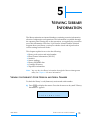
5 Viewing Library Information. . . . . . . . . . . . . . . . . . . . . . 75
Viewing the Library’s Code Version and Serial Number . . . . . . . . .
Viewing Fibre Channel Information (221L-FC) . . . . . . . . . . . . . . . .
Viewing Library Statistics . . . . . . . . . . . . . . . . . . . . . . . . . . . . . . . .
Viewing System Sensors . . . . . . . . . . . . . . . . . . . . . . . . . . . . . . . . .
Viewing Library INQUIRY Data . . . . . . . . . . . . . . . . . . . . . . . . . . .
Viewing the Cartridge Inventory . . . . . . . . . . . . . . . . . . . . . . . . . . .
Viewing Tape Drive Information. . . . . . . . . . . . . . . . . . . . . . . . . . .
75
76
78
79
80
81
83
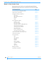
6 Using the Remote Management Utility . . . . . . . . . . . . . 87
Where to Find Instructions . . . . . . . . . . . . . . . . . . . . . . . . . . . . . . .
Accessing the Remote Management Utility . . . . . . . . . . . . . . . . . . .
Setting Configuration Options . . . . . . . . . . . . . . . . . . . . . . . . . . . .
Unlocking the Entry/Exit Port Door and Front Door . . . . . . . . . . .
Viewing Interface, Library, and Tape Drive Information . . . . . . . .
Issuing Library and Tape Drive Commands. . . . . . . . . . . . . . . . . .
88
89
91
108
110
124
7 Maintenance. . . . . . . . . . . . . . . . . . . . . . . . . . . . . . . . . 141
Installing or Replacing a Tape Drive . . . . . . . . . . . . . . . . . . . . . .
Cleaning the Library . . . . . . . . . . . . . . . . . . . . . . . . . . . . . . . . . .
Using Touch-up Paint on the Housing . . . . . . . . . . . . . . . . . . . . .
Upgrading Library Firmware and Creating Diagnostic Listings . . . .
Upgrading Tape Drive Firmware and Creating Diagnostic
Listings Using LTO Tool (221L) . . . . . . . . . . . . . . . . . . . . . . . .
141
145
145
145
153
8 Troubleshooting and Error Codes . . . . . . . . . . . . . . . . 155
Troubleshooting . . . . . . . . . . . . . . . . . . . . . . . . . . . . . . . . . . . . . . 155
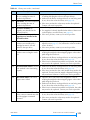
Error Codes . . . . . . . . . . . . . . . . . . . . . . . . . . . . . . . . . . . . . . . . . 158
vi
PRODUCT MANUAL
1014258
9 Shipping the Library . . . . . . . . . . . . . . . . . . . . . . . . . . 165
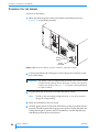
Preparing the Library for Shipping. . . . . . . . . . . . . . . . . . . . . . . . . 165
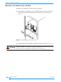
Removing the Library from the Rack . . . . . . . . . . . . . . . . . . . . . . . 166
Packing the Library . . . . . . . . . . . . . . . . . . . . . . . . . . . . . . . . . . . . 167
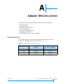
A Library Specifications . . . . . . . . . . . . . . . . . . . . . . . . . 171
Storage Capacity. . . . . . . . . . . . . . . . . . . . . . . . . . . . . . . . . . . . . .
Size and Weight . . . . . . . . . . . . . . . . . . . . . . . . . . . . . . . . . . . . . .
Performance Specifications. . . . . . . . . . . . . . . . . . . . . . . . . . . . . .
Power Specifications. . . . . . . . . . . . . . . . . . . . . . . . . . . . . . . . . . .
Environmental Specifications . . . . . . . . . . . . . . . . . . . . . . . . . . . .
Shipping Specifications . . . . . . . . . . . . . . . . . . . . . . . . . . . . . . . . .
Safety and Regulatory Agency Compliance . . . . . . . . . . . . . . . . . .
171
172
172
174
176
179
180
Index. . . . . . . . . . . . . . . . . . . . . . . . . . . . . . . . . . . . . . . . . 185
APRIL 2005
EXABYTE 221L AND 221L-FC LIBRARIES
vii
Notes
viii
PRODUCT MANUAL
1014258
ABOUT THIS MANUAL
ABOUT THIS MANUAL
This manual describes how to install, configure, operate, maintain, and
troubleshoot the Exabyte® 221L and 221L-FC LTO™ Ultrium™ Libraries. It also
provides library specifications.
WHERE TO LOOK FOR INFORMATION
Installation
If you are performing first-time installation:
Read Chapter 1, “Product Overview for an overview of the library’s features
and components.
Read Chapter 2, “Installing the Library for hardware installation
instructions, including obtaining the necessary accessories, installing
cartridges, and connecting the library to a host system.
Read Chapter 3, “Configuring the Library for configuration instructions,
including how to use the operator panel to set library options. If you want
to use the library’s Remote Management utility to set configuration options,
refer to Chapter 6, “Using the Remote Management Utility for instructions
for accessing the utility.
Operation
When you are ready to put the library into operation:
Read Chapter 4, “Operating the Library to learn about adding and removing
cartridges during operation, operating the library in sequential mode,
cleaning the tape drive(s), and performing other basic library operations.
Read Chapter 5, “Viewing Library Information to learn about viewing
information such as code versions, statistics, sensor readings, and cartridge
inventory data.
Read Chapter 6, “Using the Remote Management Utility for information
about using the library’s Remote Management utility to change
configuration options, view information, issue commands, monitor, and
manage library operation across an Ethernet network.
APRIL 2005
EXABYTE 221L AND 221L-FC LIBRARIES
IX
ABOUT THIS MANUAL
Maintenance, Troubleshooting, and Service
If you need to perform basic maintenance, troubleshoot problems, or return
the library for service:
Read Chapter 7, “Maintenance for instructions for replacing tape drives,
uploading new firmware, and creating diagnostic listings.
Read Chapter 8, “Troubleshooting and Error Codes for troubleshooting tips,
definitions of library error codes, and corrective actions for each error
situation.
Read Chapter 9, “Shipping the Library for packing and shipping
instructions if you need to return the library for service.
Specifications
To learn about specifications for the library:
Read Appendix A, Library Specifications for physical, performance,
reliability, power, environmental, and safety agency specifications.
RELATED PUBLICATIONS
The following publications provide additional information about the library.
Exabyte 221L and 221L-FC Libraries
Exabyte 221L and 221L-FC Library Quick Start Guide, 1014259
Exabyte 110L and 221L Libraries SCSI Reference, 1014275
Installing an Exabyte 221L Library or 110L Autoloader into a Rack, 1014257
Installing or Replacing a Tape Drive in an Exabyte 110L, 221L, or 221L-FC,
1006159
Exabyte Bar Code Label Specification for LTO Ultrium Cartridges, 1004080
IBM T400/T800 Ultrium Tape Drives
See the IBM web site at www.storage.ibm.com/tape/lto/oem/index.html to
locate documentation and support information for IBM LTO Ultrium tape
drives.
Standards
ANSI Information Technology — SCSI-3 Primary Commands 2 (SPC-2), ANSI
INCITS 351-2001
ANSI Information Technology — SCSI-3 Medium Changer Commands (SMC),
ANSI INCITS 314-1998
ANSI SCSI-3 Fast20 Parallel Interface (Fast-20), X3.277 – 1996
ANSI SCSI Parallel Interface-2 (SPI-2), X3T10/1142D, Rev. 11
ANSI High Performance Serial Bus, ANSI/IEEE 1394 – 1995
X
PRODUCT MANUAL
1014258
ABOUT THIS MANUAL
ANSI SCSI-3 Parallel Interface, X3.253 – 1995
ANSI SCSI-3 Fast-20 Parallel Interface, X3.277 –1996
Standard IEEE 802.3, Carrier Sense Multiple Access with Collision Detection
(CSMA/CD) Access Method and Physical Layer Specifications, 1985
TapeAlert Specification, NCITS T10/02-142R0, Version 3.0, March 2002
EIA Rack Standards, RS-310-B
The following standards are related to the Fibre Channel interface used by the
library and tape drive(s):
ANSI Information Technology Fibre Channel Protocol for SCSI (FCP), X3.269-1996
Fibre Channel Protocol for SCSI, Second Revision 2 (FCP-2), T10/Project
1144-D/Rev 4, December 1999
ANSI Information Technology Fibre Channel Physical and Signaling Standard
(FC-PH), X3.230-1994
ANSI Information Technology Fibre Channel 2nd Generation Physical and
Signaling Standard (FC-PH-2), X3.303-1998
ANSI Information Technology Fibre Channel Arbitrated Loop (FC-AL),
X3.272-1996
ANSI Information Technology Fibre Channel Arbitrated Loop (FC-AL-2), NCITS
332-1999
Information Technology Fibre Channel Fabric Loop Attachment (FC-FLA),
T11/Project 1235-DT/Rev 2.7
Fibre Channel FC-Tape Standard, T11/99 – 069v4, 1999
Fibre Channel Tape Connector Profile Using 80-pin SCA-2 Connector, T11/99 –
234v2
Specification for 40-pin SCA-2 Connector w/Bidirectional ESI, SFF-8067
Specification for 40-pin SCA-2 Connector w/Parallel Selection, SFF-8045
SCA-2 Unshielded Connections, EIA-700A0AE (SFF-8451)
Gigabit Interface Converter (GBIC), Small Form Factor, SFF-8053, Revision 5.x
Common FC-PH Feature Sets Profiles, Fibre Channel Systems Initiative,
FCSI-101-Rev. 3.1
SCSI Profile, Fibre Channel System Initiative, FCSI-201-Rev. 2.2
FCSI IP Profile, Fibre Channel System Initiative, FCSI-202-Rev. 2.1
APRIL 2005
EXABYTE 221L AND 221L-FC LIBRARIES
XI
ABOUT THIS MANUAL
CONVENTIONS USED IN THIS MANUAL
This manual uses the following conventions:
[Enter]: Boxed text indicates keys on the library’s operator panel.
Note: Notes provide additional information or suggestions about the topic or
procedure being discussed.
!
Caution
Warning
XII
Important
Read text marked by the “Important” icon for information that
will help you complete a procedure or avoid extra steps.
Read text marked by the “CAUTION” icon for information you must know to avoid
damaging the library, the tape drive(s), or losing data.
Read text marked by the “WARNING” icon for information you must know to
avoid personal injury.
PRODUCT MANUAL
1014258
1
PRODUCT OVERVIEW
The Exabyte 221L and 221L-FC LTO Ultrium tape libraries provide unattended
data storage, archiving, backup, and retrieval for midrange and high-end
workstations, servers, and networks.
The 221L library has a SCSI interface; the 221L-FC library has a Fibre Channel
interface. Both libraries are available with LTO Ultrium 1, Ultrium 2, or
Ultrium 3 Fibre Channel tape drives and feature Exabyte’s patented,
award-winning ExaBiotics™.
LIBRARY FEATURES
The Exabyte 221L and 221L-FC libraries include the following features:
Storage for up to 21 data cartridges. Cartridges are stored in two removable
cartridge magazines containing seven slots each and seven additional fixed
cartridge slots mounted next to the tape drive(s). The removable magazines
are easily accessible from the front panel and can be used with an
interlocking lid to store cartridges outside of the library.
One or two LTO Ultrium tape drives. The tape drives are installed in drive
carriers that allow easy installation and removal from the library.
APRIL 2005
EXABYTE 221L AND 221L-FC LIBRARIES
1
CHAPTER 1 PRODUCT OVERVIEW
Entry/exit port. The entry/exit port allows you to insert and remove
cartridges without opening the library’s door and interrupting operation.
Robotic cartridge handler (robot). The robot moves cartridges between the
storage slots, tape drive(s), and the entry/exit port.
Bar code scanner. The library uses a laser bar code scanner, attached to the
robot, to read bar code labels on the data cartridges. The library stores the
bar code information as part of its cartridge inventory.
Operator panel with LCD display. The operator panel allows you to
monitor library operations, select configuration options, and control the
robot from the front panel.
Wide, low-voltage differential (LVD) SCSI interface (221L). The 221L
library and SCSI LTO Ultrium tape drive(s) each support independent sets
of SCSI messages and commands and can be connected to separate LVD
SCSI buses.
Native Fibre Channel interface (221L-FC). The 221L-FC’s native Fibre
Channel interface allows seamless integration into data-intensive storage
area network (SAN) environments.
Standalone or rack-mount capability. The library is designed to operate as
a standalone unit or in a standard 19-inch rack. Rack-mounting kits are
available from Exabyte.
Ethernet port for connection to a 10/100BaseT Ethernet network. You can
connect the library to an Ethernet network for remote monitoring,
management, upgrading firmware, and creating diagnostic listings.
Built-in remote management capability. You can use the library’s built-in
Remote Management utility and a standard web browser to set
configuration options, view library information, monitor, and manage
operation over an Ethernet network.
Note:
2
PRODUCT MANUAL
Your library may include Exabyte Library Monitor software on CD.
Exabyte Library Monitor is an older program for remote monitoring
that has been replaced by the library’s built-in Remote Management
utility. The Remote Management utility is available with the latest
library firmware. You can download the latest firmware from
Exabyte’s web site (www.exabyte.com). Instructions for upgrading
library firmware are provided on page 145.
1014258
LIBRARY COMPONENTS
LIBRARY COMPONENTS
The following sections describe the library’s front panel, internal, and back
panel components.
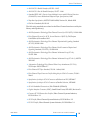
FRONT PANEL COMPONENTS
Figure 1-1 shows the library’s front panel components.
LCD
Keypad
Door
Entry/exit
port door
Figure 1-1 Front panel components
Operator Panel (LCD and Keypad) The operator panel includes a keypad
and a two-line, 32-character liquid crystal display (LCD). You can use the
operator panel to perform the following activities:
View library and tape drive status and information
Set or change library configuration options
Unlock the door
Lock and unlock the entry/exit port
Run demonstration programs and test library operations
Reset the library and tape drive(s)
Entry/Exit Port The entry/exit port door on the front of the library provides
access to the entry/exit port caddy (see Figure 1-2). This caddy allows you to
insert or remove a single cartridge without opening the library door.
To help maintain cartridge security and to provide safety from possible laser
beam exposure, a solenoid-activated lock secures the caddy in the entry/exit
port.
APRIL 2005
EXABYTE 221L AND 221L-FC LIBRARIES
3
CHAPTER 1 PRODUCT OVERVIEW
Door The door allows manual access to the library’s internal components,
including the tape drive(s), cartridge magazines, and fixed cartridge slots.
To help maintain cartridge security and to provide safety from possible laser
beam exposure, the door is secured by a solenoid-activated electronic locking
system. The library will not operate when the door is unlocked.
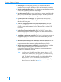
INTERNAL COMPONENTS
Figure 1-2 shows the internal components of the 221L. Except for the Fibre
Channel interface on the tape drive, the components described in this section
are identical for the 221L-FC.
Robot
Entry/exit
port caddy
Tape drive in carrier
Cartridge
magazines
Fixed cartridge
slots
Figure 1-2 Internal components
4
PRODUCT MANUAL
1014258
LIBRARY COMPONENTS
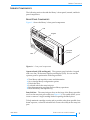
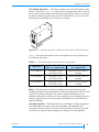
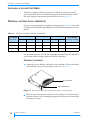
LTO Ultrium Tape Drives The library contains one or two LTO Ultrium tape
drives. As shown in Figure 1-3, each tape drive is installed in a drive carrier to
allow it to be easily inserted and removed from the library. When you remove
the data cartridge magazines from the front of the library, you can access the
tape drive(s) to manually load or remove a cartridge.
Figure 1-3 LTO Ultrium tape drive installed in a drive carrier (SCSI drive shown)
Table 1-1 shows the data transfer rates and capacities for each generation of
LTO Ultrium tape drive.
Table 1-1 LTO Ultrium tape drive transfer rates and capacities
Maximum Data Transfer
Rate (2:1 Compression)
Maximum Data Capacity
(2:1 Compression)
LTO Ultrium 1
15 MB per second
(108 GB per hour)
200 GB on one Ultrium 1
cartridge
LTO Ultrium 2
35 MB per second
(252 GB per hour)
400 GB on one Ultrium 2
cartridge
LTO Ultrium 3
80 MB per second
(576 GB per hour)
800 GB on one Ultrium 3
cartridge
Tape Drive
Robot The robot picks and places cartridges, moving them between the
cartridge storage locations, tape drive(s), and the entry/exit port. The bar code
scanner is located on the robot. The scanner enables the library to read
information from bar code labels on the cartridges into its cartridge inventory.
A library application can use the inventory information to locate and move
specific cartridges.
Cartridge magazines The library holds two removable cartridge magazines.
Each magazine stores up to seven data cartridges. The magazine slots
incorporate design features to ensure that the cartridges are always inserted
correctly and to prevent the cartridges from falling out of the magazine.
MAY 2005
EXABYTE 221L AND 221L-FC LIBRARIES
5
CHAPTER 1 PRODUCT OVERVIEW
Bottom
mounting
slot
A
0
0
A
0
0
0
0
A
1
0
0
L1
0
0
A
1
0
0
L1
0
0
A
1
0
0
L1
0
0
A
1
0
0
L1
0
0
1
0
L1
0
1
L1
A
0
0
0
0
1
L1
The magazine, shown in Figure 1-4, has alignment guides on the top and
mounting slots on the bottom. These features align with guides on the
magazine holder to ensure secure and accurate positioning of the magazine
inside the library.
Top alignment
guides
Figure 1-4 Data cartridge magazine
Fixed Cartridge Slots The library contains seven fixed cartridge slots located
to the left of the tape drive(s). If desired, you can configure the fixed cartridge
slot closest to the tape drive(s) to hold a cleaning cartridge.
6
PRODUCT MANUAL
1014258
LIBRARY COMPONENTS
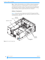
BACK PANEL COMPONENTS
Figure 1-5 shows the back panel components of the 221L. Figure 1-6 shows the
back panel components of the 221L-FC.
Drive carrier
Drive bay service
access cover
Library SCSI
connectors
Tape drive
SCSI connectors
Ethernet port
9-pin
serial port
Tape drive fan
System fan
Power entry
module
Figure 1-5 Back panel components (221L)
Drive carrier
Library optical
fiber connector
Ethernet port
Drive bay service
access cover
Tape drive
optical fiber
connector
9-pin
serial port
Tape drive fan
System fan
Power entry
module
Figure 1-6 Back panel components (221L-FC)
APRIL 2005
EXABYTE 221L AND 221L-FC LIBRARIES
7
CHAPTER 1 PRODUCT OVERVIEW
Drive Carriers and Service Access Covers The library contains one or two
LTO Ultrium tape drives installed in Exabyte drive carriers. In the 221L, each
drive carrier includes two SCSI connectors for connecting the tape drive to a
SCSI bus. In the 221L-FC, each drive carrier includes one integrated dual LC
optical fiber connector for connecting the tape drive to a single loop on a Fibre
Channel network.
The drive carrier allows the tape drive to be easily inserted and removed from
the library. The drive carrier includes a fan to maintain the operating
temperature of the tape drive. If your library contains only one tape drive, the
unused drive slot is protected by a drive bay service access cover.
Library SCSI Connectors (221L) The 221L library has two 68-pin, wide LVD
SCSI connectors for connection to a SCSI bus. The connectors accommodate
either two SCSI cables or a cable and an external terminator. The library can be
on the same bus as the tape drive(s) or on a separate bus.
Library Fibre Channel Connector (221L-FC) The 221L-FC library has one
integrated dual LC optical fiber connector for connection to a Fibre Channel
network. The library can be on the same loop as the tape drive(s) or on a
separate loop.
Ethernet Port The Ethernet port allows you to connect the library to a
10/100BaseT Ethernet network. You can use the Ethernet connection to
perform the following activities:
Monitor and manage library operation remotely
Download diagnostic information from the library
Upgrade the library’s firmware
9-Pin Serial Port A 9-pin serial port allows the library to be connected
directly to a computer for diagnostics and firmware upgrades.
Power Entry Module The library chassis is grounded through the power
entry module. The module includes the power cord connection and the power
switch. The power cord connection provides AC power to the internal power
supply for the library and the tape drive(s). The power switch allows you to
turn power on and off for the library and the enclosed tape drive(s).
Fans The system fan provides cooling for the library. Each drive carrier also
includes a fan to provide optimal cooling for the enclosed tape drive.
8
PRODUCT MANUAL
1014258
2
INSTALLING THE LIBRARY
This chapter describes how to install the library hardware. Depending on your
requirements, installation will involve most of the following steps:
Unpacking the library
Obtaining accessories and equipment
Preparing for installation
Installing the library in a rack
Installing a second tape drive
Preparing and installing cartridges
Connecting the library to SCSI (221L)
Connecting the library to Fibre Channel (221L-FC)
Connecting the library to Ethernet
Powering on the library
Verifying the hardware installation
APRIL 2005
EXABYTE 221L AND 221L-FC LIBRARIES
9
CHAPTER 2 INSTALLING THE LIBRARY
UNPACKING THE LIBRARY
No special tools are required for unpacking the library. Save all the original
packing materials, including the accessory box, in case you need to ship or
move the library later.
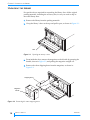
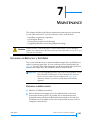
1. Remove the library from the packing materials.
2. Grasp the library’s door at the top and pull it open, as shown in Figure 2-1.
ES
CA
PE
EN
TE
R
ST
AT
US
ME
NU
UN
LO
DO CK
OR
RE
SE
T
Door
Figure 2-1 Opening the library’s door
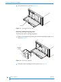
3. From inside the door, remove the magazine on the left side by grasping the
handle, shown in Figure 2-2, and pulling the magazine straight out.
4. Remove the robot shipping brace from the magazine, as shown in
Figure 2-2.
Shipping brace
Magazine
handle
Figure 2-2 Removing the robot shipping brace
10
PRODUCT MANUAL
1014258
OBTAINING ACCESSORIES AND EQUIPMENT
OBTAINING ACCESSORIES AND EQUIPMENT
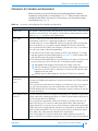
Make sure that you have all the accessories and equipment for library
installation and operation, as indicated in Table 2-1. Many of these items are
included in the library accessory box. If necessary, you can purchase items
from Exabyte (see page iv).
Table 2-1 Accessories and equipment for installation and operation
Accessories and Equipment
Power Cord
Two power cords are provided with the library: one for use in the US and Canada
and one for use in Europe. If you plan to use the library outside of these locations,
refer to page 175 for power cord requirements.
SCSI Cables
(221L)
Two SCSI cables are provided with the library: one for connecting a host computer
to the library, and one for connecting the library to a tape drive.
You will need one or more additional cables if you plan to install a second tape
drive in the library or if you plan to attach multiple SCSI buses to the library.
You can purchase SCSI cables from Exabyte or provide your own. If you want to
use your own cables, follow these guidelines:
Use wide LVD SCSI cables that conform to SCSI-3 specifications. To comply
with the regulations and standards listed in Appendix A, all SCSI cables used
with the library must be properly shielded.
The maximum allowable length of an LVD SCSI bus is 12 meters (39 feet) if you
have more than two devices on the bus. To determine the bus length:
a. Add together the lengths of all external SCSI cables on the bus.
b. Add 23 centimeters (9 inches) for the internal cable length used by each
tape drive on the bus and 5 centimeters (2 inches) for the internal cable
length used by the robot.
c. Add the internal cable lengths for any other SCSI devices on the bus.
SCSI Bus
Terminator(s)
(221L)
One SCSI terminator is provided with the library.
You may need additional terminators if you have more than one SCSI bus attached
to the library.
You can purchase terminators from Exabyte or provide your own. If you want to
use your own terminators, use active terminators such as the AMP 796051-1
(SE/LVD Multi-mode) SCSI terminator. Termination must be external; do not use
internal terminators.
Fibre Channel Cables No Fibre Channel cables are included with the library. The number of optical fiber
cables required for attaching the library to a Fibre Channel network depends on
(221L-FC)
how many tape drives are installed.
You can purchase optical fiber cables from Exabyte or provide your own. Use
either 50-micron or 62.5-micron multi-mode optical fiber cables with dual
single-channel (LC) connectors. If you choose 50-micron multi-mode optical fiber
cables, they must comply with the 100-M5-SN-I classification as specified in the
Fibre Channel standard (FC-PI). If you choose 62.5-micron multi-mode optical
fiber cables, they must meet the 100-M6-SN-I classification.
Note: The length of 62.5 micron multi-mode cables should not exceed 275
meters. Operation over distances greater than 275 meters cannot be guaranteed.
APRIL 2005
EXABYTE 221L AND 221L-FC LIBRARIES
11
CHAPTER 2 INSTALLING THE LIBRARY
Table 2-1 Accessories and equipment for installation and operation (continued)
Accessories and Equipment
Second Tape Drive
(Optional)
The library is shipped with one tape drive installed. If desired, you can install a
second tape drive. Contact Exabyte for tape drive upgrade kits
Ethernet Cable
A shielded Ethernet cable is provided with the library. You can use this cable to
connect the library to an Ethernet network for remote monitoring, management,
firmware upgrades, and diagnostics.
If you want to provide your own Ethernet cable, use a shielded Category 5
(10/100BaseT connection) data-grade cable or similar Category 5 cable that is
compliant with EIA/TIA 568. The library’s Ethernet port connector is a
pin-through-hole RJ-45 shielded connector.
To comply with the regulations and standards listed in Appendix A, all Ethernet
cables used with the library must be properly shielded.
Serial Cable
(Optional)
If you want to connect to the library’s Console interface for firmware upgrades
and diagnostics, use a straight-through 9-pin serial cable (not a null modem cable).
Bar Code Labels
Sample bar code labels are included with the library. If you want to prepare your
own labels, refer to the Exabyte Bar Code Label Specification for LTO Ultrium
Cartridges on the documentation CD.
Cartridges
One or more data cartridges and a cleaning cartridge may be included. Use only
data and cleaning cartridges designed specifically for LTO Ultrium tape drives:
The LTO Ultrium 1 tape drive uses Ultrium 1 data cartridges, which are black
(100 GB, native).
The LTO-2 tape drive supports Ultrium 1 data cartridges and Ultrium 2 data
cartridges, which are purple (200 GB, native).
The LTO-3 tape drive supports Ultrium 3 data cartridges, which are slate blue
(400 GB, native). It can also read and write Ultrium 2 cartridges and read
Ultrium 1 cartridges.
LTO Ultrium cleaning cartridges.
For maximum capacity, use Ultrium 2 data cartridges with the LTO-2 tape drive
and Ultrium 3 data cartridges with the LTO-3 tape drive.
You can purchase LTO Ultrium ExaPaks (7 data cartridges in a cartridge magazine)
from Exabyte.
Rack-Mount
Hardware (Optional)
If you want to install the library in a rack, contact Exabyte for the rack-mount kit.
12
PRODUCT MANUAL
1014258
PREPARING FOR INSTALLATION
PREPARING FOR INSTALLATION
Before you begin installing the library, do the following:
Make sure that the SCSI host bus or Fibre Channel adapter card installed
in the host computer, any necessary device drivers, and your backup
software are compatible with the library. Compatibility information is
available at www.exabyte.com. If your software application has not yet been
certified for the 221L library, you can use one of the library’s emulation
modes (see page 43). You can install the software on the host computer
before or after library installation. However, if you install the software first,
you may need to reconfigure it for use with the library after library
installation is complete.
For SCSI configurations, plan the SCSI bus connections for the library and
make sure you have the necessary SCSI cables and terminators. The
library can include up to three SCSI devices: the library itself and two tape
drives. If desired, you can connect each device to a different SCSI bus. Before
beginning installation, determine how many SCSI buses you will connect to
the library and which bus you will connect to which device (see page 18 for
guidelines). Obtain the required SCSI cables and terminators for these
connections.
For Fibre Channel configurations, plan the Fibre Channel connections and
make sure you have the necessary hardware and optical fiber cables to
connect the library and tape drive(s) to the network. Before beginning
installation, determine how many cables you will need and how they will be
connected to Fibre Channel hubs, switches, or hosts (see page 20 for
guidelines).
Locate an appropriate area for the library. The library must be operated on
a level surface. There must be approximately 15 cm (6 inches) of open area
behind the library for adequate air flow.
Ensure that the work area is free from conditions that could cause
electrostatic discharge (ESD). Discharge static electricity from your body by
touching a known grounded surface, such as a computer’s metal chassis.
Warning
Before performing any installation or maintenance procedures, be sure that the
library’s power switch is off and that the power cord is disconnected from the
library and the outlet.
INSTALLING THE LIBRARY IN A RACK
The library is designed to operate as a standalone unit or in a standard 19-inch
rack. If you plan to use the library in a rack and have obtained the rack-mount
kit from Exabyte, install the library in the rack using the instructions provided
in the kit.
APRIL 2005
EXABYTE 221L AND 221L-FC LIBRARIES
13
CHAPTER 2 INSTALLING THE LIBRARY
INSTALLING A SECOND TAPE DRIVE
The library is shipped with one tape drive installed. If you plan to install a
second tape drive and have obtained the tape drive kit from Exabyte, install
the drive using the instructions provided in the kit or on page 141.
PREPARING AND INSTALLING CARTRIDGES
Be sure to use the appropriate cartridges for the tape drive. Table 2-2 shows the
cartridge and write/read compatibility for the LTO Ultrium tape drives in the
library.
Table 2-2 Tape drive cartridge read/write compatibility
LTO Ultrium Ultrium 3 (slate blue)
Tape Drive
Read
Write
Ultrium 2 (purple)
Ultrium 1 (black)
Read
Write
Read
Write
LTO Ultrium
cleaning cartridge
LTO-3
No
LTO-2
No
No
LTO-1
No
No
No
No
For maximum capacity, use Ultrium 2 cartridges with the Ultrium 2 tape drive
and Ultrium 3 data cartridges with the Ultrium 3 tape drive.
PREPARING CARTRIDGES
1. If desired, you can affix bar code labels to the cartridges. Position each label
in the indented area on the cartridge, as shown in Figure 2-3.
0
0
0
A
Bar code label
0
1
L1
Write-protect switch
Figure 2-3 Bar code label placement and write-protect switch location
2. Make sure the write-protect switch on each cartridge is set for the desired
operation. Refer to your cartridge packaging for instructions for setting the
write-protect switch.
14
PRODUCT MANUAL
1014258
PREPARING AND INSTALLING CARTRIDGES
INSTALLING CARTRIDGES IN THE FIXED SLOTS
1. Open the library’s door, as shown on page 10.
2. Remove each magazine by grasping the handle and pulling straight out, as
shown in Figure 2-4.
Magazine
handle
Figure 2-4 Removing a magazine
3. Install cartridges into the fixed slots, with the write-protect switches down
and facing out, as shown in Figure 2-5.
Fixed slot
Figure 2-5 Installing cartridges in the fixed slots
Note: If your software license limits the number of cartridge slots you can use,
you may need to configure the library to use less than 21 slots (see
page 48).
APRIL 2005
EXABYTE 221L AND 221L-FC LIBRARIES
15
CHAPTER 2 INSTALLING THE LIBRARY
4. If you plan to use a cleaning cartridge to clean the tape drive(s), place the
cleaning cartridge in the fixed slot closest to the tape drive(s), as shown in
Figure 2-6. To use this slot for a cleaning cartridge, you must set the Clean
Slot option during library configuration (described on page 44).
Cleaning cartridge
slot (optional)
Figure 2-6 Installing a cleaning cartridge
Note: If you are using a cleaning cartridge and also set the Max Addressable Slot
option (see page 48) to less than 21 slots, place the cleaning cartridge in
the highest addressable slot. For example, if you configure the library to
use 14 slots, place the cleaning cartridge in slot 14. See page 69 for the
cartridge numbering scheme.
Caution
Do not use cleaning cartridges other than those approved for LTO Ultrium tape
drives. Using other types of cleaning cartridges will void your warranty.
Carefully follow all instructions and recommendations provided with the cleaning
cartridge.
16
PRODUCT MANUAL
1014258
PREPARING AND INSTALLING CARTRIDGES
INSTALLING CARTRIDGES IN THE MAGAZINES
Write-protect
switch
A
0
0
A
0
0
0
0
A
1
0
0
L1
0
0
A
1
0
0
L1
0
0
A
1
0
0
L1
0
0
A
1
0
0
L1
0
0
1
0
L1
0
1
L1
A
0
0
0
0
1
L1
1. Install cartridges in each magazine so that the write-protect switches are
positioned away from the alignment guides, as shown in Figure 2-7.
Magazine
alignment guides
Figure 2-7 Installing cartridges in a magazine
2. Insert each cartridge magazine into the library so that the alignment guides
are up (as shown in Figure 2-8) and the alignment grooves are down.
!
Important The magazine fits only one way; do not try to force it into the
library. If the magazine does not slide in easily, check its
orientation and re-insert it.
Magazine
alignment guides
Figure 2-8 Installing a magazine in the library
3. Close the library’s door.
APRIL 2005
EXABYTE 221L AND 221L-FC LIBRARIES
17
CHAPTER 2 INSTALLING THE LIBRARY
CONNECTING THE LIBRARY TO SCSI (221L)
This section provides guidelines for connecting the library to host systems via
SCSI. The 221L library and its tape drive(s) have independent wide LVD
(low-voltage differential) SCSI interfaces and can be connected to a single or
separate SCSI buses.
Note: To ensure optimum tape drive performance, connect the tape drive to an
Ultra3 (Ultra160) SCSI host bus adapter.
GUIDELINES FOR CONNECTING TO SCSI
Before connecting the library and its tape drive(s) to SCSI, determine how
many SCSI buses you will be using, which bus will connect to which device,
and how many cables and terminators you will require. Keep in mind these
guidelines as you plan your SCSI connections:
For best performance, avoid connecting more than two LTO tape drives to
the same SCSI bus. You can connect a library with two LTO tape drives to a
single SCSI bus, but avoid placing additional LTO tape drives, whether
standalone or in other libraries, on the same SCSI bus.
Do not connect single-ended SCSI devices. Although single-ended SCSI is
compatible with LVD Ultra2 and Ultra3 (Ultra160) SCSI, Exabyte does not
support single-ended devices on the SCSI buses attached to the library or its
tape drive(s).
Do not connect the library to a RAID controller. The library will not operate
if it is connected to a RAID controller.
Do not exceed SCSI bus length restrictions. The maximum allowable length
of an LVD SCSI bus is 12 meters (39 feet) if you have more than two devices
on the bus. Make sure none of the buses attached to the library or its tape
drive(s) exceed this length. To determine the length of each bus:
a. Add together the lengths of all external SCSI cables on the bus.
b. For each bus attached to a tape drive, add 23 centimeters (9 inches) for
the internal cable length used by each tape drive on the bus.
c. For the bus attached to the library, add 5 centimeters (2 inches) for the
internal cable length used by the library.
d. Add the internal cable lengths for any other SCSI devices on the bus.
Make sure each SCSI bus is properly terminated. You must install a
terminator on the device at the physical end of each bus. Typically, one of the
library’s tape drives will terminate the bus. See page 11 for terminator
requirements.
18
PRODUCT MANUAL
1014258
CONNECTING THE LIBRARY TO SCSI (221L)
MAKING THE SCSI CONNECTIONS
To connect the library and its tape drive(s) to SCSI:
1. Make sure that the library is powered off.
2. Power off the host computer(s) and any peripheral devices on the SCSI
bus(es).
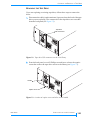
3. Connect a SCSI cable to the host and to one of the library’s SCSI connectors,
shown in Figure 2-9.
!
Important Do not over-tighten the SCSI cable jack screws.
Tape drive
SCSI connectors
Library
SCSI connectors
Figure 2-9 Location of library and tape drive SCSI connectors
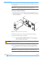
4. Connect other SCSI cables, as necessary, depending on your bus
configuration. If the library and tape drive(s) will share one bus, use jumper
cables to daisy-chain the library and tape drive connectors, as shown in
Figure 2-10.
APRIL 2005
EXABYTE 221L AND 221L-FC LIBRARIES
19
CHAPTER 2 INSTALLING THE LIBRARY
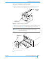
5. For the device at the physical end of each bus, install a terminator on one of
the SCSI connectors for that device.
Library
SCSI connectors
Jumper cables
Terminator
Tape drive
SCSI connectors
SCSI cable
(to host)
Figure 2-10 Cabling for a shared SCSI bus
6. Power on all of the peripheral devices on the SCSI bus(es).
7. Power on the library as described on page 24.
CONNECTING THE LIBRARY TO FIBRE CHANNEL (221L-FC)
This section provides instructions for connecting the 221L-FC library and its
tape drive(s) to a Fibre Channel network.
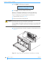
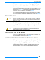
Figure 2-11 shows the back panel of the 221L-FC. The library has one
integrated dual single-channel LC optical fiber connector, Port A, which is
used to connect the library to a single loop on a Fibre Channel network. Each
tape drive also includes one integrated dual LC optical fiber connector, Port A,
for connecting the tape drive to a Fibre Channel network. The library can be
on the same loop as the tape drive(s) or on a separate loop.
Library optical
fiber connector
Tape drive
optical fiber
connector
Figure 2-11 Fibre Channel connectors on the back of the 221L-FC
20
PRODUCT MANUAL
1014258
CONNECTING THE LIBRARY TO FIBRE CHANNEL (221L-FC)
In a Fibre Channel environment, you can connect the library and tape drive(s)
to a Fibre Channel hub or switch in an arbitrated loop or a switched fabric. For
simplicity in these instructions, each of these situations is referred to as a
“network.”
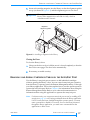
To connect the library and its tape drive(s) to a Fibre Channel network:
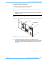
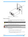
1. Remove the protective plugs (if present) from the library’s optical fiber
connector and the optical connectors on each tape drive (see Figure 2-12).
Library optical fiber
fiber connector
Protective plugs
Figure 2-12 Removing the protective plugs from the optical fiber connectors
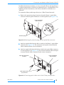
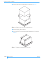
2. Attach an optical cable from the hub or switch to the library’s optical fiber
connector (see Figure 2-13). The connectors are keyed to ensure that the
cable is attached in the correct orientation.
3. Attach an optical cable from the hub or switch to the optical fiber connector
on each tape drive (see Figure 2-13). The connector and the cable are keyed
to ensure that the cable is attached in the correct orientation.
Tape drive optical fiber
connector
Library optical fiber
fiber connector
Dual single-channel
(LC) connector
Figure 2-13 Connecting optical cables to the 221L-FC library and tape drive
APRIL 2005
EXABYTE 221L AND 221L-FC LIBRARIES
21
CHAPTER 2 INSTALLING THE LIBRARY
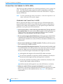
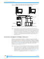
Figure 2-14 shows a schematic representation of a possible configuration for
integrating the library and tape drives into an arbitrated loop.
Server
Server
Server
Server
Switchor hub
Switch
Library Robot
Tape Drive
Workstation
Tape Drive
Disk
Array
Disk array
Tape library
Figure 2-14 221L-FC library and tape drives connected to an arbitrated loop
Note: Once the library has been powered on and the Fibre Channel loop has
been initialized, avoid disconnecting the library from the loop. If you need
to disconnect the library from the loop, use the utility provided with your
switch or hub to bypass the affected ports before breaking the connection.
The bypass sets the port to a non-participating state on the loop. When
you have reconnected the library, use the utility to return the port to a
participating state.
CONNECTING THE LIBRARY TO ETHERNET (OPTIONAL)
If desired, you can connect the library to an Ethernet network to remotely
monitor and manage library operation, create diagnostic listings, and upgrade
library firmware. You can use the library’s built-in Remote Management utility
and a standard web browser to remotely configure, monitor, and manage the
library (see Chapter 6). For information about upgrading firmware and
creating diagnostic listings, see page 145.
Note: Your library may include Exabyte Library Monitor software on CD. Exabyte
Library Monitor is an older program for remote monitoring that has been
replaced by the library’s built-in Remote Management utility. The Remote
Management utility is available with the latest library firmware. You can
download the latest firmware from Exabyte’s web site (www.exabyte.com).
Instructions for upgrading library firmware are provided on page 145.
22
PRODUCT MANUAL
1014258
CONNECTING THE LIBRARY TO ETHERNET (OPTIONAL)
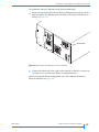
To connect the library to Ethernet using the provided cable:
1. Insert one end of the cable into the library’s Ethernet port until you hear it
snap into place. The Ethernet port is located on the back of the library, as
shown in Figure 2-15.
Ethernet port
Figure 2-15 Location of Ethernet port (221L shown)
2. Connect the other end of the cable to the network or directly to the server
you plan to use to monitor the library or upload firmware.
When you perform library configuration, you will configure the library’s
Ethernet interface (see page 38).
APRIL 2005
EXABYTE 221L AND 221L-FC LIBRARIES
23
CHAPTER 2 INSTALLING THE LIBRARY
POWERING ON THE LIBRARY
To power on the library:
1. Make sure that the power switch on the back of the library, shown in
Figure 2-16, is off (the 0 is pressed).
Power
switch
Power
connector
Figure 2-16 Location of library’s power connector and power switch
2. Connect the female end of the power cord to the power connector on the
back of the library.
!
Important Two power cords are shipped with the library: One for use in the
US and Canada, and one for use in Europe. Use the correct power
cord for your location. See page 175 for power cord requirements
for other locations.
3. Plug the male end of the power cord into the power source.
Note:
The library has autoranging voltage selection, so you do not need to
change the voltage setting.
4. Make sure the library’s door is closed.
5. Push the power switch on the back of the library to the on position (the I is
pressed). The library performs its power-on sequence. During this time, the
cooling fans begin to operate, the LCD illuminates, and the tape drive(s)
and library perform power-on self-tests.
24
PRODUCT MANUAL
1014258
VERIFYING THE HARDWARE INSTALLATION
6. Power on the host computer system(s).
!
Important Do not power on the host computer system(s) immediately after
powering on the library. After you press the library’s power switch,
there is a short delay before the tape drives are on-line.
POWERING OFF THE 221L-FC
To avoid reinitializing the Fibre Channel loop when you power off the
221L-FC, use the utility provided with your switch or hub to bypass the ports
used by the library and tape drive(s). When you are ready to power the library
back on, use the utility to place the affected ports back into the loop, then
power up the library.
VERIFYING THE HARDWARE INSTALLATION
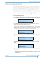
After the library powers on, the LCD displays the Status screen. As shown in
the example below, the first line of the Status screen displays the product
name and the second line shows status for the tape drive(s) (ready, no tape
loaded). If two drives are installed, the second line continuously cycles
through status messages for Drive 1 and Drive 2.
Note: Drive 1 is the tape drive closest to the fixed cartridge slots; Drive 2 is
located directly to the right of Drive 1.
E x a b y t e
2 2 1 L
1 R e a d y - N o T a p e
If the library powered on as described, continue with library configuration in
Chapter 3.
If the library did not power on as described, check the following:
Is the power switch on?
Is the power cord inserted correctly?
Is the library’s door closed?
Is each SCSI bus terminated (221L)?
Are the SCSI cables firmly connected to the library, tape drive(s), and host
computer(s) (221L)?
Are the devices on each SCSI bus attached to the library all LVD (221L)?
Are the Fibre Channel cables firmly connected to the library, tape drive(s),
and Fibre Channel hub or switch (221L-FC)?
Is the host computer system turned on?
Is there an error code displayed on the library LCD? (See Chapter 8 for an
explanation of the LCD error codes.)
If you cannot resolve the problem yourself, contact Exabyte Technical Support
(see page iv).
APRIL 2005
EXABYTE 221L AND 221L-FC LIBRARIES
25
CHAPTER 2 INSTALLING THE LIBRARY
NOTES
26
PRODUCT MANUAL
1014258
3
CONFIGURING THE LIBRARY
After installing the library hardware, you are ready to set configuration
options. This chapter describes how to:
Access configuration options
Set configuration options
Check the setup
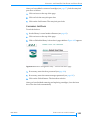
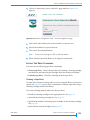
ACCESSING CONFIGURATION OPTIONS
With the 221L or 221L-FC library, you can use the operator panel or the
library’s web-based Remote Management utility to access configuration
options. If you plan to use the Remote Management utility, refer to Chapter 6
for information about accessing the utility and instructions for setting
configuration options through the utility.
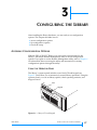
USING THE OPERATOR PANEL
The library’s operator panel includes a two-line LCD and keypad (see
Figure 3-1) that allow you to interactively control library operations. Using the
operator panel, you can set library options, check operating statistics, and
diagnose errors.
LCD
Keypad
Figure 3-1 Library LCD and keypad
APRIL 2005
EXABYTE 221L AND 221L-FC LIBRARIES
27
CHAPTER 3 CONFIGURING THE LIBRARY
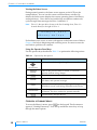
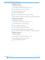
Viewing the Status Screen
During normal operation, the Status screen appears on the LCD (see the
example below). You can use this screen to monitor library activities. By
default, the Status screen displays the current operating status of the library
and tape drive(s). If two drives are installed, the second line continuously
cycles through status messages for Drive 1 and Drive 2.
Note: Drive 1 is the tape drive closest to the fixed cartridge slots; Drive 2 is
located directly to the right of Drive 1.
E x a b y t e
2 2 1 L
1 R e a d y - N o T a p e
If a hardware error occurs, an error code appears on the Status screen. Refer to
Chapter 8 for help in diagnosing and correcting errors. You must correct the
error before operation can continue.
Using the Operator Panel Keys
Use the operator keys described in Table 3-1 to perform the following actions:
Table 3-1 Operator key descriptions
Key
Action
Move up, down, left, or right through the menus and screens.
(Arrow keys)
[ESCAPE]
Return to the previous menu or screen, or cancel an
operation without saving changes.
[ENTER]
Select the item next to the screen arrow or accept a change.
[STATUS]
Display the Status screen, which shows library status, tape
drive status, and operator messages.
[MENU]
[UNLOCK{DOOR]
[RESET]
Display a menu of options for configuring the library, viewing
information screens, and issuing commands to the library.
Stop robot operations and release the door’s interlock
mechanism. The door can then be opened manually.
Reset the library and tape drive(s).
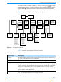
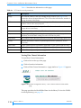
OVERVIEW OF LIBRARY MENUS
To access the library’s menus, press [MENU] on the keypad. The first menu to
appear is “Cartridge Inventory.” Press the up and down arrow keys to loop
through the menu options.
28
PRODUCT MANUAL
1014258
A CCESSING CONFIGURATION OPTIONS
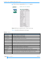
If a menu contains a triangle symbol (), you can either press [ENTER] to access
another screen or menu, or you can change values using the operator keys. A
square symbol (J ) indicates that the screen contains viewable information
only.
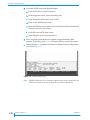
Figure 3-2 shows the organization of the operator panel menus.
Main Menu
Status Screen
Cartridge
Inventory
SCSI Menu
(221L)
Robot Mode
– SCSI
– Sequent1
– Sequent2
– Remote
– LCD
– Console
Security
– SCSI IDs
– Emulation Mode
– SCSI Parity
– Option
Fibre Menu
(221L-FC)
Config Menu
– Baud Rate Menu
– Clean Slot (xx)
– Option
– Autoclean Option
– Cleaning Tape
Cycles Left
– POST Barcode
Scan Option
– Verify Barcode
Checksums
– Max Addressable
– Slot
– Override Drive WWN
– Port Address
– Loop IDs
– Hard Loop IDs
– Req. Hard ID Option
– Emulation Mode
– World-Wide Names
– Library Node
– Library Port A
– Library Port B
– Drive n Node
– Drive n Port A
– Drive n Port B
Command
Menu
Ethernet Menu
Drive Menu
– Ethernet
– Configuration
– Network Address
– IP Address
– SNMP Recipient
– Subnet Mask
– Gateway Addr
– Ethernet Security
– Read
– Write
– Bcast
– FTP Username
– FTP Password
– Drive n Menu
– Drive n Status
– Unload Drive n
– Clean Drive n
Sequential Mode
– Loop
– Restart
– Next Cartridge
Library
Information
Lock/Unlock
Entry/Exit Port
– Move Cartridge
– Initialize Element
– Status
– Home Robot
– Park
– Position to Element
– Self Test
– Cycle Entry/Exit Lock
– Cycle Pick/Put
– Cycle Reach
– Cycle X-Axis
– Cycle Wrist
– Cycle Solenoid
Demo Menu
Park and Unlock
for Shipping
– Code Version
– Library Serial
– Num
– System Statistics
– System Sensors
– Def Inq Vend ID
– Def Inq Prod ID
Figure 3-2 Library menu structure
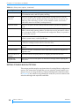
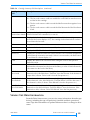
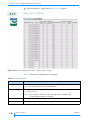
Table 3-2 provides an overview of the menu options.
Table 3-2 Library menu options
Menu Option
Description
Security
Indicates whether options can be changed from the operator panel and allows you
to enable or disable security with a password.
Cartridge Inventory
Displays the current inventory information for each library element.
Config Menu
Displays the current baud rate setting for the serial port and allows you to change
the baud rate, reserve the last cartridge slot for use with a cleaning cartridge,
enable Autoclean, choose whether the library scans the cartridge bar code labels
during POST, choose whether bar code label checksums are verified, set the
maximum number of cartridge slots the library uses, and override the world-wide
names (WWNs) for the tape drives.
Robot Mode
Displays the current robot control mode (SCSI, Sequent1, Sequent2, Remote,
LCD, or Console) and allows you to change the mode.
APRIL 2005
EXABYTE 221L AND 221L-FC LIBRARIES
29
CHAPTER 3 CONFIGURING THE LIBRARY
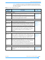
Table 3-2 Library menu options (continued)
Menu Option
Description
SCSI Menu (221L)
Displays the SCSI IDs for the library and tape drive(s). Allows you to set the SCSI
IDs, emulation mode, and SCSI parity checking.
Fibre Menu
(221L-FC)
Allows you to specify the Loop IDs for the library and tape drive(s), view the
current Loop IDs, specify whether the library and tape drive(s) use hard or soft
addressing when obtaining Loop IDs, set the emulation mode, and view the
world-wide names for the library and tape drive(s).
Sequential Mode
Allows you to specify how the library functions when it operates in sequential
mode.
Ethernet Menu
Displays the current network addressing method, IP address, SNMP recipient
address, subnet mask, gateway address, and Ethernet security information. Allows
you to change the library’s FTP password and configure the library for operation
on an Ethernet network.
Library Information
Displays information about the library’s code versions, serial number, system
statistics, system sensors, and INQUIRY data.
Drive Menu
Displays the status of the selected tape drive and allows you to issue commands
to unload a cartridge from that drive or clean the drive.
Demo Menu
Allows you to run various demonstration programs to observe how the library
operates.
Command Menu
Allows you to issue commands for basic robot motion operations and perform
diagnostic tests.
Park and Unlock for
Shipping
Moves the robot to the park position for shipping and unlocks the door.
Unlock/Lock
Entry/Exit Port
Allows you to remove and replace an individual cartridge without opening the
library door.
SETTING CONFIGURATION OPTIONS
This section provides step-by-step instructions for setting library configuration
options. The instructions assume that you are using the operator panel to set
options. If you are using the library’s Remote Management utility (described
in Chapter 6), the selections are generally the same, but you access menus and
selections through web-style links and fields.
30
PRODUCT MANUAL
1014258
SETTING CONFIGURATION OPTIONS
Table 3-3 provides an overview of each configuration option. Read through
the table to determine which options you need to set, then follow the steps on
the referenced pages.
Table 3-3 Library configuration options
Configuration
Option
Description
See...
SCSI Configuration (221L)
SCSI IDs
Setting SCSI IDs is required for 221L library operation. View the
default settings and change them if necessary.
SCSI Parity
By default, parity checking is enabled. If desired, you can disable
parity checking for the library if the SCSI adapter card connected to
the library does not support parity checking.
“Setting SCSI
Configuration
Options (221L)”
on page 32
Fibre Channel Configuration (221L-FC)
Hard Loop IDs
Require Hard
ID
Override Drive
WWN
You can request specific Loop IDs to be used by the library and tape “Setting Fibre
drive(s) during Fibre Channel initialization.
Channel
Configuration
You can specify whether the library always attempts to obtain the
Options
specified Hard Loop ID (hard addressing) or accepts an ID assigned
(221L-FC)” on
by the loop if the Hard Loop ID is unavailable (soft addressing).
page 34
You can specify whether the tape drives use the world-wide names
(WWNs) set by their manufacturer or WWNs generated by the
library. Overriding the tape drives’ WWNs allows you to replace a
tape drive without causing it to report a new WWN to an
application.
Ethernet Configuration
Ethernet
Addresses
If you are using the library’s Ethernet interface, you can set the
library’s IP address, SNMP recipient address, subnet mask, and
gateway address for communication across your Ethernet network.
You can also choose whether the library uses a fixed IP address
(static addressing) or an address assigned by a DHCP server.
Ethernet
Security
If you need to identify the library’s SNMP settings to a
network-based monitoring application, you can view the library’s
Read, Write, and Broadcast community access strings. If desired,
you can change these settings from their default values.
You can also view and set the library’s FTP user name and password
used for transferring firmware files and creating diagnostic listings.
“Setting Ethernet
Configuration
Options” on
page 38
Emulation
Emulation
Mode
APRIL 2005
Setting an emulation mode is required if your application software “Changing the
does not support a 221L, but does support an Exabyte 210, 430, or Emulation Mode”
480 library.
on page 43
EXABYTE 221L AND 221L-FC LIBRARIES
31
CHAPTER 3 CONFIGURING THE LIBRARY
Table 3-3 Library configuration options (continued)
Configuration
Option
Description
See...
Automatic Tape Drive Cleaning
These options allow you to set up automatic tape drive cleaning.
Cleaning Slot
Cleaning Cycles Note: To use automatic cleaning, a cleaning cartridge must be
installed (see page 16).
Autoclean
“Setting up
Automatic Tape
Drive Cleaning”
on page 44
Bar Code Scanning
POST Bar Code You can set this option to cause the library to automatically scan all “Setting Bar Code
Scan
bar code labels whenever the door is opened and closed or the
Scanning
library is powered on. By default, this option is turned off.
Options” on
page 46
Verify Barcode This option instructs the library to verify checksums on bar code
Checksums
labels. By default, this option is turned off.
Number of Slots Used
Max
Addressable
Slot
This option allows you to configure the library so that it uses and
reports fewer slots than are physically present. You can set this
option if your software application bases licensing on the number of
slots being used and you are using fewer than the full number of
slots in the library. If your software does not monitor the number of
slots, you do not need to set this option. By default, the library
reports 21 slots.
“Limiting the
Number of Slots
Used (Max
Addressable Slot
Option)” on
page 48
By setting LCD security, you prevent unauthorized personnel from
disrupting the operation of the library through the operator panel.
“Setting up
Library Security”
on page 49
Security
LCD Security
SETTING SCSI CONFIGURATION OPTIONS (221L)
This section describes how to:
Set SCSI IDs for the library and tape drive(s)
Set SCSI parity checking
Setting the SCSI IDs
The library and its tape drive(s) are independent SCSI devices that can be
attached to the same SCSI bus or to separate SCSI buses. Each device attached
to a SCSI bus must have a unique SCSI ID within that bus. Because you may
have multiple buses, the library does not check for duplicate SCSI IDs. Make
sure you do not assign duplicate IDs within a bus.
32
PRODUCT MANUAL
1014258
SETTING CONFIGURATION OPTIONS
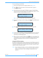
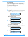
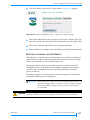
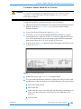
To view and change the SCSI IDs:
1. If the security option has been enabled, disable it (see page 50).
2. Press [MENU] to display the menus. The first menu item to appear is
“Cartridge Inventory.”
3. Press the down arrow key until “SCSI Menu” appears. The SCSI Menu
screen shows the current ID settings. In the example below, Drive 1 is set to
01, Drive 2 is set to 02, and the library is set to 00.
S C S I
D 0 1
Note:
M e n u
0 2
L 0 0
Drive 1 is the tape drive closest to the fixed cartridge slots.
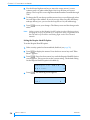
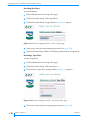
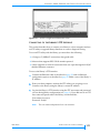
4. If you want to change any of the settings, press [ENTER]. The SCSI IDs screen
appears.
S C S I
D 0 1
I D s
0 2
L 0 0
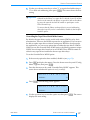
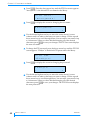
5. Press [ENTER] again to display the next screen for changing the IDs.
I D s ?
D 0 1
¦
0 2
L 0 0
→
6. To select a drive or the library, use the left and right arrow keys to move the
screen arrow (¦) across columns. To change the ID, use the up and down
arrow keys to scroll through values.
7. When you have set all the SCSI IDs, press [ENTER] to save your changes. The
screen displays a status message for each ID you changed. When the library
has finished changing the IDs, the SCSI IDs screen displays the new
settings.
Setting the SCSI Parity Option
By default, the library checks all data coming across the SCSI bus for parity. If
desired, you can disable parity checking for the library if the SCSI adapter card
connected to the library does not support parity checking. The parity setting
remains in effect across power cycles.
Note: Parity checking for the library can also be enabled through the application
software. The method used last to set parity checking (operator panel or
software) has precedence. Parity checking for the tape drive(s) is set
separately.
APRIL 2005
EXABYTE 221L AND 221L-FC LIBRARIES
33
CHAPTER 3 CONFIGURING THE LIBRARY
To set parity checking:
1. If the security option has been enabled, disable it (see page 50).
2. Press [MENU] to display the menus (or return to the top of the menu
selections). Press the down arrow key until “SCSI Menu” appears on the
screen, then press [ENTER].
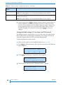
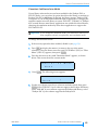
3. Press the down arrow key until “SCSI Parity” appears, as shown below. This
screen shows whether parity is enabled (1) or disabled (0).
S C S I
O p t
P a r
i o n :
i
t y
1
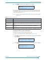
4. Press [ENTER]. The following screen appears.
S C S I
P a r
i
t y ?
1 ↓
5. Use the up or down arrow key to select “1” to turn parity checking on or “0”
to turn parity checking off, then press [ENTER]. The screen shows the new
setting.
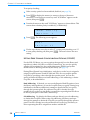
SETTING FIBRE CHANNEL CONFIGURATION OPTIONS (221L-FC)
For the 221L-FC library, you can set options that specify how the library and
tape drive(s) obtain Loop IDs on a Fibre Channel loop. You can also specify
whether the tape drives use the world-wide names (WWNs) set by their
manufacturer or WWNs generated by the library (see page 37).
During Fibre Channel loop initialization, each device on the loop is assigned a
unique Loop ID between 0 and 125 (00h and 7Dh). You can request specific
Loop IDs by specifying values through the operator panel. You can also
specify whether the library uses hard addressing or soft addressing to obtain
Loop IDs, as described below.
Hard Addressing If desired, you can use the Require Hard ID option to force
the library and tape drive(s) to use the Loop IDs that you specify. During loop
initialization, the library and drive(s) attempt to obtain the IDs you specify
through the operator panel. If a requested Loop ID is already in use by
another device on the loop, the library or tape drive requesting that ID will not
be able to participate on the Fibre Channel loop.
Soft Addressing By default, the library and tape drive(s) use soft addressing
to obtain their Loop IDs. When using soft addressing, the library and tape
drive(s) first attempt to obtain the Loop IDs you specify through the operator
panel. If an ID is already in use by another device on the loop, the library or
drive requesting that ID is assigned an another available ID.
34
PRODUCT MANUAL
1014258
SETTING CONFIGURATION OPTIONS
Setting the Loop IDs
To set the Loop IDs for the library and tape drive(s):
1. If the security option has been enabled, disable it (see page 50).
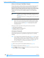
2. Press [MENU] to display the menus. Press the down arrow key until “Fibre
Menu” appears. The Fibre Menu screen shows the current Loop ID for each
tape drive and the library. Each ID is a two-digit hexadecimal number.
In the following example, Drive 1 is 01, Drive 2 is 02, and the library is set to
00.
F
i b r e
D 0 1
M e n u
0 2
L 0 0
Drive 1 is the tape drive closest to the fixed cartridge slots; Drive 2 is
located directly to the right of Drive 1.
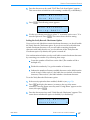
Note:
The second line of the Fibre Menu may include one of the codes listed in
Table 3-4 instead of a Loop ID.
Table 3-4 Loop ID codes
Loop ID Code
Description
?
The Loop ID is unknown because the Loop Initialization
process (LIP) is not complete.
HW
The library’s Fibre Channel interface card is not installed.
B
A drive blank is installed at this tape drive location.
SA
Soft addressing is in use.
NP
The library or tape drive is in a non-participating mode
because it could not obtain a Loop ID.
3. Press [ENTER]. Press the down arrow key until the Hard Loop IDs screen
appears.
H a r d
D 0 1
L o o p
0 2
I D s
L 0 0
4. Press [ENTER] again to display the next screen for changing the Loop IDs.
I D s ?
D 0 1
¦
APRIL 2005
0 2
L 0 0
→
EXABYTE 221L AND 221L-FC LIBRARIES
35
CHAPTER 3 CONFIGURING THE LIBRARY
5. Use the left and right arrow keys to move the screen arrow (¦) across
columns until it is under either digit of the Loop ID that you want to
change. The Loop ID is a two-digit hexadecimal number from 00h through
7Dh.
6. To change the ID, use the up and down arrow keys to scroll through values
for each digit of the address. If you do not care what Loop IDs the library
and tape drive(s) use, you can set the Loop IDs to SA (soft addressing).
7. Press [ENTER] to save your changes. The library resets and the changes take
effect.
Note: Unless you turn on the Require Hard ID option (see the following section),
changing the Loop ID of the library or a tape drive does not guarantee that
the selected Loop ID will be used during login on the Fibre Channel
network.
Setting the Require Hard ID Option
To set the Require Hard ID option:
1. If the security option has been enabled, disable it (see page 50).
2. Press [MENU] to display the menus. Press the down arrow key until “Fibre
Menu” appears.
3. Press [ENTER]. Press the down arrow key until the Require Hard ID Option
screen appears. This screen shows the current setting. The default setting
for the Require Hard ID option is disabled (0).
R e q u
O p t
i
r e
H a r d
I D
i o n :
0
4. Press [ENTER]. The following screen appears.
R e q u i
I D ?
36
PRODUCT MANUAL
r e
H a r d
0
↑
1014258
SETTING CONFIGURATION OPTIONS
5. Use the up or down arrow key to select “1” to require hard addressing or
“0” to allow soft addressing, then press [ENTER]. The screen shows the new
setting.
!
Important If you turn on the Require Hard ID option, and the Loop ID you
selected for the library or a tape drive is already in use by another
device on the network, the library or tape drive will not be able to
log onto the network and will be unable to participate on the
Fibre Channel loop.
To ensure that the library and tape drive(s) use soft addressing
when the Loop ID you set is unavailable, disable (0) the Require
Hard ID option.
Overriding the Tape Drive World-Wide Names
By default, the tape drives use the world-wide names (WWNs) set by their
manufacturer. These are the WWNs reported to an application. If you want to
be able to replace tape drives without causing new WWNs to be reported to
the application, you can set an option that overrides the tape drives’ WWNs.
When you use the Override Drive WWN option, the library generates unique
WWNs for each tape drive based on its own WWN. These WWNs remain in
effect for any tape drives installed in the two tape drive bays.
To set the Override Drive WWN option:
1. If the security option has been enabled, disable it (see page 50).
2. Press [MENU] to display the menus. Press the down arrow key until “Config
Menu” appears, then press [ENTER].
3. Press the down arrow key until “Override Drive WWN” appears. This
screen shows whether the option is on (1) or off (0).
O v e r
r
i d e
D r
i v e
WWN :
0
4. Press [ENTER]. The following screen appears.
¦ O v e r
WWN :
r
i d e
D r
i v e
0 ↑
5. Use the up arrow key to turn the option on, then press [ENTER]. The screen
displays the new setting.
APRIL 2005
EXABYTE 221L AND 221L-FC LIBRARIES
37
CHAPTER 3 CONFIGURING THE LIBRARY
6. Reset the tape drive (see page 66) to cause the new WWNs to take effect.
!
Important If you remove a tape drive after the Override Drive WWN option
has been in effect, the library-generated WWN stays with the tape
drive. If you want the tape drive to revert to its original WWN,
you must turn off the Override Drive WWN option and reset the
tape drive before removing it from the library.
SETTING ETHERNET CONFIGURATION OPTIONS
If desired, you can connect to the library’s Ethernet interface to remotely
monitor and manage operation, upgrade firmware, and create diagnostic
listings. Instructions for connecting the library to Ethernet are provided on
page 22. For information about using the library’s Remote Management utility,
see Chapter 6.
Configuring the library’s Ethernet interface typically involves specifying the
library’s IP address, subnet mask, and gateway address. The IP address is used
to route information from the library to the server. You can choose between
dynamic (server-assigned) or static (user-assigned) addressing for the IP
address. The subnet mask is used to route information to designated devices
within the network. The gateway address allows information to be routed
outside the subnet. You can also view and set the library’s SNMP (Simple
Network Management Protocol) recipient IP address.
If you are using a network-based library monitor/management application
other than the library’s Remote Management utility, you may need to identify
the library’s SNMP settings to the application. These settings include the read,
write, and broadcast community strings. You can view these settings on the
Ethernet Security screens, but you cannot change their values from the
operator panel. If you need to change the values for these strings, you can use
the library’s Console interface. See page 146 for information about connecting
to the Console interface.
The library also includes an FTP interface that you can use to transfer
firmware files or create diagnostic listings. You can set up an FTP user name
and password for this interface or use the library’s defaults. See page 151 for
instructions for accessing the library’s FTP interface and using an FTP utility
to upgrade firmware or obtain diagnostic listings.
38
PRODUCT MANUAL
1014258
SETTING CONFIGURATION OPTIONS
Setting the Ethernet Addresses
To set the Ethernet addresses:
1. If the security option has been enabled, disable it (see page 50).
2. Press [MENU] to display the menus. Press the down arrow key until “Ethernet
Menu” appears.
E t h e r n e t
S
0 .
M e n u
0 .
0 .
1
3. Press [ENTER]. The Ethernet Configuration menu appears.
E t h e r n e t
C o n f
i g u r a t
i o n
4. Press [ENTER]. The Network Address screen appears.
N e t w o r k
A d d r e s s : S t a t
i c
There are five screens for setting Ethernet addresses: Network Address, IP
Address, SNMP Recipient, Subnet Mask, and Gateway Address. Press the
down arrow key to view each screen. The options are described in Table 3-5.
Table 3-5 Ethernet address configuration options
Ethernet Address
Option
Description
Network address
Selects the method used to set the Internet Protocol (IP) address for the library, as
follows:
Static – The library uses a fixed IP Address, which is assigned in the IP Address
option, described below.
DHCP – The library uses an IP address assigned by the network DHCP (Dynamic
Host Configuration Protocol) server.
Static addressing is recommended. Dynamic assignment of the library’s IP address
may require periodic reinstallation or reconfiguration of some monitoring software
applications.
IP Address
Sets the IP address for the library or displays the IP address obtained by the DHCP
server.
SNMP Recipient
Sets the IP address for the SNMP trap recipient.
APRIL 2005
EXABYTE 221L AND 221L-FC LIBRARIES
39
CHAPTER 3 CONFIGURING THE LIBRARY
Table 3-5 Ethernet address configuration options (continued)
Ethernet Address
Option
Description
Subnet Mask
Sets the subnet mask for the library.
Note: This option displays “N/A” if the network address is set to DHCP.
Gateway Address
Sets the default TCP/IP (Transmission Control Protocol/Internet Protocol) gateway
address for the library.
Note: This option displays “N/A” if the network address is set to DHCP.
5. At each screen, press [ENTER] to display another screen for setting values. To
change addresses, use the left and right arrow keys to move the screen
arrow (¦) across columns until it is under a digit you want to change. Use
the up and down arrow keys to scroll through values. When you have
finished changing all of the desired values, press [ENTER] to save your
changes.
Viewing the SNMP Settings, FTP User Name, and FTP Password
The Ethernet Security screens allow you to view the read-only values for the
library’s Read, Write, and Broadcast community access strings. You can also
view and change the library’s FTP user name and password.
To view the Ethernet security screens:
1. If the security option has been enabled, disable it (see page 50).
2. Press [MENU] to display the menus. Press the down arrow key until “Ethernet
Menu” appears.
E t h e r n e t
S
0 .
M e n u
0 .
0 .
1
3. Press [ENTER]. The Ethernet Configuration menu appears.
E t h e r n e t
C o n f
i g u r a t
i o n
4. Press the down arrow key until “Ethernet Security” appears.
E t h e r n e t
S e c u r
40
PRODUCT MANUAL
i
t y
1014258
SETTING CONFIGURATION OPTIONS
5.
Press [ENTER]. The first screen to appear is shown below.
R e a d :
“ P u b l
i c “
There are five Ethernet security screens: Read, Write, Bcast (Broadcast), FTP
User, and FTP User PW. Press the down arrow key to view each screen. The
screens are described inTable 3-6.
Note: If security is enabled (either from the LCD or SCSI), these options display
asterisks (****).
Table 3-6 Ethernet security screens
Ethernet Security
Description
Read
Displays the library’s alphanumeric Read community string. The default is public.
Write
Displays the library’s alphanumeric Write community string. The default is public.
Bcast (Broadcast)
Displays the library’s alphanumeric Broadcast community string. The default is
public.
FTP User
Displays the library’s FTP user name, up to 16 characters. The default is
anonymous.
FTP PW (Password)
Displays the library’s FTP password, up to 16 characters. The default is Exabyte.
Changing the FTP User Name and Password
To change the library’s FTP user name and password:
1. If the security option has been enabled, disable it (see page 50).
2. Press [MENU] to display the menus. Press the down arrow key until “Ethernet
Menu” appears.
E t h e r n e t
S
0 .
0 .
M e n u
0 .
1
3. Press [ENTER]. Press the down arrow key until “Ethernet Security” appears.
E t h e r n e t
S e c u r
APRIL 2005
i
t y
EXABYTE 221L AND 221L-FC LIBRARIES
41
CHAPTER 3 CONFIGURING THE LIBRARY
4. Press [ENTER]. Press the down arrow key until the FTP User screen appears.
“Anonymous” is the default FTP user name for the library.
F T P
U s e r
:
“ a n o n y m o u s “
5. Press [ENTER] to display the screen for changing the user name.
a n o n y m o u s
→
¦
6. Use the left and right arrow keys to move the screen arrow (¦) across
columns until it is under a character you want to change. Use the up and
down arrow keys to scroll through letters. You can enter a user name of up
to 16 characters. When you have finished changing all of the desired
characters, press [ENTER] to save your changes. The FTP User screen displays
the new user name.
7. To change the FTP password, press the down arrow key until the FTP PW
screen appears. “Exabyte” is the default FTP password for the library.
F T P
P W :
“ E x a b y t e “
8. Press [ENTER] to display the screen for changing the password.
E x a b y t e
¦
→
9. Use the left and right arrow keys to move the screen arrow (¦) across
columns until it is under a character you want to change. Use the up and
down arrow keys to scroll through letters. You can enter a password of up
to 16 characters. When you have finished changing all of the desired
characters, press [ENTER] to save your changes. The FTP PW screen displays
the new password.
42
PRODUCT MANUAL
1014258
SETTING CONFIGURATION OPTIONS
CHANGING THE EMULATION MODE
If your library software has not yet been certified for the Exabyte 221L or
221L-FC library, you can select an option that allows the library to emulate an
Exabyte 210, 430, or 480 library. By default, the library returns “Exabyte 221L”
in response to a SCSI INQUIRY command from an application. Changing the
emulation mode causes the library to return “EXB-210,” “EXB-480,“or “Exabyte
430” instead. Because most library applications are certified for these libraries,
changing the emulation mode may allow these applications to support the
221L and 221L-FC.
!
Important If you change the emulation mode, you will need to reboot your
host computer so that it recognizes the new emulation mode.
To change the emulation mode:
1. If the security option has been enabled, disable it (see page 50).
2. Press [MENU] to display the menus (or return to the top of the menu
selections). Press the down arrow key until “SCSI Menu” (221L) or “Fibre
Menu” (221L-FC) appears, then press [ENTER].
3. Press the down arrow key until “Emulation Mode” appears, as shown
below. This screen shows the current mode.
E m u
l a t
i o n
M o d e :
N o n e
4.
Press [ENTER]. The following screen appears.
E m u l a t
N o n e
i o n
M o d e ?
¦
5. Use the up or down arrow key to select an emulation mode, then press
[ENTER]. Select “EXB-210” if your software supports the Exabyte 210 library;
select “EXB-480” if your software supports the Exabyte 480 library; select
“Exabyte 430” if your software supports the Exabyte 430.
APRIL 2005
EXABYTE 221L AND 221L-FC LIBRARIES
43
CHAPTER 3 CONFIGURING THE LIBRARY
SETTING UP AUTOMATIC TAPE DRIVE CLEANING
The Autoclean option enables the library to automatically perform tape drive
cleaning without operator intervention. When Autoclean is enabled, the
library monitors the cleaning requirements of the tape drive(s). When a drive
indicates a “Needs Cleaning” status, the robot removes the cleaning cartridge
from its slot and inserts it into the tape drive. After the cleaning cycle is
complete, the robot returns the cleaning cartridge to its slot and resumes
operation.
!
Important If you plan to use automatic cleaning, make sure that you have
installed a cleaning cartridge in the cleaning cartridge slot location
(see page 16).
If your library software has a cleaning option, be sure to turn that
option OFF.
Note: You do not have to use the library’s Autoclean option to clean the tape
drive(s). You can choose from several other cleaning methods, including
using your software’s cleaning function and using commands available
through the operator panel. See page 63 for information about these
cleaning alternatives.
Setting up automatic tape drive cleaning involves three procedures:
Activating the cleaning slot
Setting the number of cleaning cycles
Enabling the Autoclean option
Activating the Cleaning Slot
Activating the Clean Slot option designates the right-most fixed cartridge slot
(closest to the tape drives) as a permanent storage location for a cleaning
cartridge.
Note: If you change the Max Addressable Slot option (see page 48), the location
of the cleaning slot changes. The cleaning cartridge slot, if used, is always
the highest storage element address enabled. For example, if you change
the Max Addressable Slot option to 14, then the cleaning slot will be 14.
For more information on storage element addresses, see page 69.
To activate the Clean Slot option:
1. If the security option has been enabled, disable it (see page 50).
2. Change the control mode to LCD (see page 54).
3. Press [MENU] to display the menus. Press the down arrow key until “Config
Menu” appears, then press [ENTER].
44
PRODUCT MANUAL
1014258
SETTING CONFIGURATION OPTIONS
4. Press the down arrow key to display “Clean Slot Option,” then press [ENTER].
The Clean Slot Option screen shows which slot is designated as the
cleaning slot (21 in the example below) and whether the option is on (1) or
off (0).
C l
e a n
O p t
5.
S l o t
( 2 1 )
i o n :
0
Press [ENTER]. The following screen appears.
C l e a n i n g
S l o t
S l o t
a t
0 ↑
2 1 ?
6. Press the up or down arrow key to select “1” to turn the fixed cleaning slot
option on or “0” to turn it off, then press [ENTER]. The screen shows the
current selection.
Setting the Number of Cleaning Cycles
The Cleaning Tape Cycles Left option is a counter that tracks the number of
times a cleaning cartridge has been used. When you install a new cleaning
cartridge, you must use this option to set the number of cleaning cycles that
remain. After completing a cleaning cycle, the library automatically decreases
the Cleaning Tape Cycles Left counter by one.
Note: Refer to the information provided with your LTO Ultrium cleaning
cartridge to determine how many cleaning cycles it contains.
To set the Cleaning Tape Cycles Left option:
1. If the security option has been enabled, disable it (see page 50).
2. If necessary, press [MENU] to display the menus. Press the down arrow key
until “Config Menu” appears, then press [ENTER].
3. Press the down arrow key to display “Cleaning Tape Cycles Left.”
C l
e a n i n g
C y c l e s
T a p e
L e f
t
:
1
4. Press [ENTER]. The following screen appears.
C l e a n i n g
L e f
t ?
C y c l e s
1 ↑
5. Use the arrow keys to set the number of cleaning cycles that remain on the
installed cleaning cartridge, then press [ENTER].
APRIL 2005
EXABYTE 221L AND 221L-FC LIBRARIES
45
CHAPTER 3 CONFIGURING THE LIBRARY
Enabling the Autoclean Option
After setting up the cleaning slot and the number of cleaning cycles remaining,
you can turn on autocleaning by enabling the Autoclean option:
1. If the security option has been enabled, disable it (see page 50).
2. If necessary, press [MENU] to display the menus. Press the down arrow key
until “Config Menu” appears, then press [ENTER].
3. Press the down arrow key until “Autoclean Option” appears. This screen
shows whether Autoclean is enabled (1) or not (0).
A u t o c
O p t
l e a n
i o n :
0
4. Press [ENTER]. The following screen appears.
A u t o c l e a n
D r
i v e s ?
0 ↑
5. Press the up or down arrow key to select “1,” which turns on the Autoclean
option, or “0” to turn the option off, then press [ENTER].
Note:
When the Cleaning Tape Cycles Left counter reaches zero, the library
disables Autoclean and displays a message on the Status screen that
reminds you to replace the cleaning tape.
SETTING BAR CODE SCANNING OPTIONS
If you are using bar code labels with your cartridges, you can set options that
determine when the library scans all of the cartridge labels and whether the
library verifies checksum characters on the labels.
Setting the POST Bar Code Scan Option
When the POST Bar Code Scan option is enabled, the library automatically
scans the bar code labels whenever the library’s door is opened and closed or
whenever the library is powered up. By default, this option is turned off.
Enabling this option increases the amount of time the library requires to
complete POST (power-on self-test).
To turn on the POST Bar Code Scan option:
1. If the security option has been enabled, disable it (see page 50).
2. Press [MENU] to display the menus (or return to the top of the menu
selections). Press the down arrow key until “Config Menu” appears, then
press [ENTER].
46
PRODUCT MANUAL
1014258
SETTING CONFIGURATION OPTIONS
3. Press the down arrow key until “POST Bar Code Scan Option” appears.
This screen shows whether bar code scanning is enabled (1) or disabled (0).
P O S T
B a r c o d e
S c a n
O p t
i o n :
0
4. Press [ENTER]. The following screen appears.
S c a n
d u r
b a r c o d e s
i n g
P O S T ?
0
5. Use the up or down arrow key to select “1” to turn the option on or “0” to
turn the option off. Press [ENTER]. The screen shows the new setting.
Setting the Verify Barcode Checksums Option
If you use bar code labels that contain checksum characters, you should enable
the Verify Barcode Checksums option. If you do not use bar code labels that
include checksum characters or if you mix labels containing checksum
characters with labels that do not, you should turn off the Verify Barcode
Checksums option. By default, this option is turned off.
You can determine whether your bar code labels contain checksum characters
by contacting your vendor or by following these steps:
a. Count the number of black bars on the label. (The number will be a
multiple of 5.)
b. Divide this number by 5 to get the number of characters.
c. Subtract the number of human-readable characters on the label from the
result of step b. If the result is 2, the label does not include a checksum
character; if the result is 3, the label includes a checksum character.
To set the Verify Barcode Checksums option:
1. If the security option has been enabled, disable it (see page 50).
2. Press [MENU] to display the menus (or return to the top of the menu
selections). Press the down arrow key until “Config Menu” appears on the
screen, then press [ENTER].
3. Press the down arrow key until “Verify Barcode Checksums” appears. This
screen shows whether the option is enabled (1) or disabled (0).
V e r
i
f y
B a r c o d e
C h e c k s u m s :
APRIL 2005
0
EXABYTE 221L AND 221L-FC LIBRARIES
47
CHAPTER 3 CONFIGURING THE LIBRARY
4. Press [ENTER]. The following screen appears.
V e r
i
f y
B a r c o d e
C h e c k s u m s ?
0
5. Use the up or down arrow key to select “1” to turn the option on or “0” to
turn the option off. Press [ENTER]. The new setting appears on the screen.
LIMITING THE NUMBER OF SLOTS USED (MAX ADDRESSABLE SLOT
OPTION)
Some library applications base licensing fees on the number of cartridge slots
in the library. If you don’t plan to use all of the slots in the library initially, use
the Max Addressable Slot option to limit the number of slots used and
reported to the application. When the Max Addressable Slot is set to a value
less than 21 (the default), the library will not allow any commands with source
or destination element addresses greater than that number.
To set the Max Addressable Slot option:
1. If the security option has been enabled, disable it (see page 50).
2. Change the control mode to LCD (see page 54).
3. Press [MENU] to display the menus (or return to the top of the menu
selections). Press the down arrow key until “Config Menu” appears on the
screen, then press [ENTER].
4. Press the down arrow key until “Max Addressable Slot” appears. This
screen shows the current value (21).
M a x
A d d r e s s a b l e
S l o t
2 1
5. Press [ENTER]. The following screen appears.
M a x
A d d r e s s a b l e
S l o t ?
2 1 ↓
6. Use the up or down arrow key to select the desired slot number, then press
[ENTER]. The screen displays the new setting.
48
PRODUCT MANUAL
1014258
SETTING CONFIGURATION OPTIONS
SETTING UP LIBRARY SECURITY
To prevent unauthorized users from disrupting library operation, you can set
up a password for accessing operator panel menus, using the entry/exit port,
and opening the door. You can enable or disable security in either of the
following ways:
From the operator panel (LCD security). You can set the security option
from the LCD, as described in this section.
Through your library application (SCSI security). If your application
supports this feature, you can issue commands from the application to turn
security on and off. Refer to your software documentation for information.
Note: Whichever method you use to enable security (operator panel or
application), you must also use to disable security. That is, if you enable
security from the LCD, you must disable it from the LCD. If you enable
security through your application (SCSI), you must disable it through the
application.
When you enable security, the following activities are prevented:
Changing the robot control mode
Changing configuration settings (except baud rate)
Changing the SCSI Menu options
Changing the Fibre Menu options
Changing the Ethernet Menu options
Cleaning the tape drive(s)
Using the Demo Menu
Using the Command Menu
Unlocking the entry/exit port (LCD security only)
Unlocking and opening the door (LCD security only)
If you attempt to perform any of these operations when security is enabled,
the library displays a message that states security is active.
!
Important LCD security includes prevention of access through the entry/exit
port and door. If you enable security through your application,
access through the entry/exit port and door is not prevented.
Separate commands for preventing entry/exit port and door
access may be available through your application. Refer to your
software documentation for information.
Note: If you are using the library’s Remote Management utility (see Chapter 6),
you can set up a password in the utility to prevent unauthorized users from
accessing menu items through the utility that would disrupt operation. This
password is separate from the password set for LCD security.
APRIL 2005
EXABYTE 221L AND 221L-FC LIBRARIES
49
CHAPTER 3 CONFIGURING THE LIBRARY
Enabling Security from the Operator Panel (LCD Security)
To enable LCD security:
1. Press [MENU] to display the menus (or return to the top of the menu
selections). Press the down arrow key until “Security” appears. This screen
shows whether security is currently enabled or disabled.
S e c u r
i
t y
D i s a b l e d
2. Press [ENTER]. An informational message appears, then the following screen
appears.
P a s s w o r d ?
0 0 0
¦
3. Use the left and right arrow keys to move across the columns. Use the up
and down arrow keys to select a number. When you have selected a
password, press [ENTER]. A prompt similar to the one below appears.
P a s s w o r d :
0 0 0
A c c e p t ?
4. Press [ENTER] to accept the new password. The Security screen then displays
“LCD Password.”
Note: Once enabled, security remains in effect through resets and power cycles.
Disabling Security from the Operator Panel
To disable LCD security:
1. Press [MENU] to display the menus (or return to the top of the menu
selections). Press the down arrow key until “Security” appears. If security is
enabled, “LCD Password” appears on this screen.
Note:
Security may have been enabled by your application using a SCSI
command (the LCD will display “SCSI”). If this is the case, security
must be disabled by your application.
S e c u r
L C D
50
PRODUCT MANUAL
i
t y
P a s s w o r d
1014258
CHECKING THE SETUP
2. Press [ENTER]. The following screen appears.
P a s s w o r d ?
0 0 0
¦
3. Enter the LCD security password set previously. Use the left and right
arrow keys to move across the columns. Use the up and down arrow keys
to select a number. Press [ENTER]. Security is disabled.
CHECKING THE SETUP
After configuring the library, check the setup by performing the exercises
suggested below. While these exercises are not required, it is a good idea to
verify that your software and hardware are properly communicating before
you begin operation.
Use the options on the Demo Menu or Command Menu to exercise the
hardware. These exercises help determine whether the library hardware
components are operating properly. See page 69 for instructions.
Note:
These hardware exercises require changing the control mode to LCD,
as described on page 54. When you complete the exercises, be sure
to change the library’s control mode back to SCSI, which is the
standard operating mode for the library.
If you have not already done so, install the software application on the host
computer. Instruct the software to perform a cartridge load and unload
operation for each tape drive. This test helps determine whether the
software and library are communicating properly.
Back up several megabytes of data to each tape drive and perform a
comparison check on the backed-up data. This determines whether the
software and tape drive(s) are communicating properly.
If the library and tape drive(s) are not operating as expected, see Chapter 8 for
troubleshooting and error code information. If you cannot resolve the
problem yourself, contact Exabyte Technical Support (see page iv).
APRIL 2005
EXABYTE 221L AND 221L-FC LIBRARIES
51
CHAPTER 3 CONFIGURING THE LIBRARY
NOTES
52
PRODUCT MANUAL
1014258
4
OPERATING THE LIBRARY
After you have configured the library, you can put it into operation. If you
operate your library in SCSI mode, your library application controls which
cartridges are moved to and from the tape drive(s). If you operate the library
in one of the sequential modes (see page 60), the library automatically
processes the cartridges in sequential order. In both cases, your backup
application controls backup and restore jobs in the tape drive(s).
Before beginning operation, always make sure that:
The robot does not contain a cartridge.
The cartridge magazines are installed.
The library’s door is closed.
The library is in the proper control mode. SCSI is the standard operating
mode (see page 54).
You can monitor library operation by viewing the operator panel or by using
the library’s Remote Management utility (see Chapter 6). The Status screen
(see page 28) provides continuous updates on the activities of the library and
tape drive(s).
During normal operation, you do not need to intervene in library activities.
However, you may occasionally need to perform the following tasks,
described in this chapter.
Change the robot control mode
Open the door to access cartridge magazines or tape drive(s)
Remove and add cartridges through the entry/exit port
Operate the library in sequential mode
Clean the tape drive(s)
Reset the library and tape drive(s)
Eject a cartridge
Perform hardware exercises
Store cartridges that you have removed from the library
APRIL 2005
EXABYTE 221L AND 221L-FC LIBRARIES
53
CHAPTER 4 OPERATING THE LIBRARY
CHANGING THE ROBOT CONTROL MODE
The robot control mode determines the source of commands issued to the
robot to move cartridges. You can set the library to one of the following control
modes: SCSI, Sequent1, Sequent2, Remote, LCD, or Console. These control
modes allow you to operate the library with application software (SCSI),
operate the library as a stacker device (Sequent1 and Sequent2), control robot
motion from the Remote Management utility (Remote), control robot motion
from the operator panel (LCD), or perform diagnostic functions (Console).
Note: Control mode settings remain through power cycles.
The robot control modes are described in Table 4-1.
Table 4-1 Robot control modes
Control Mode
Description
SCSI
This is the standard operating mode and the default setting for the library. When
the library is operating in SCSI mode, the motion of the robot is controlled by
application software running on the host computer.
Note: An application can issue commands to the library regardless of the
control mode. However, the library must be in SCSI mode for the
application to control robot motion.
Sequent1
and
Sequent2
In the sequential modes, no library application is required to control robot motion.
The library’s internal firmware instructs the robot to pick all cartridges sequentially,
from the first cartridge in the magazines through the last cartridge in the fixed slots
(or the last data cartridge slot specified by the Max Addressable Slot option, as
described on page 48). In Sequent1 mode, the cartridges are processed in Drive
1 only. In Sequent2 mode, the cartridges are processed in Drive 2 only.
Remote
When the library is operating in Remote mode, you control the motion of the
robot by issuing commands from the library’s Remote Management utility (see
Chapter 6).
Note: You can monitor library operation through the Remote Management
utility without setting the library to Remote mode. You only need to use
Remote mode when you want to control robot motion from the Remote
Management utility.
LCD
When the library is operating in LCD mode, you control the motion of the robot
by issuing commands through the library’s operator panel. You can use this mode
to move cartridges and perform hardware exercises and demos.
Note: You can use most operator panel functions without setting the library to
LCD mode. You only need to use LCD mode when you want to control
robot motion from the operator panel.
Console
When the library is operating in Console mode, robot motion is controlled from a
terminal connected to the library’s serial port.
Note: You do not need to switch to Console mode if you want to create
diagnostic listings for technical support or upgrade firmware. For
information about these tasks, see page 145.
54
PRODUCT MANUAL
1014258
OPENING AND CLOSING THE LIBRARY’S DOOR
To change the robot control mode:
1. If the security option has been enabled, disable it (see page 50).
2. Press [MENU] to display the menus, then press the down arrow until “Robot
Mode” appears. The Robot Mode screen shows the current mode.
R o b o t
M o d e
S C S I
3. Press [ENTER]. An informational message appears, then the following screen
appears.
R o b o t
S C S I
M o d e ?
¦
4. Use the arrow keys to select the desired mode and press [ENTER]. The screen
shows the new selection.
OPENING AND CLOSING THE LIBRARY ’S DOOR
You can access the cartridges and tape drive(s) by opening the library’s door.
!
Important Avoid opening the library’s door to replace individual cartridges
during library operation. Opening and closing the door interrupts
operation and causes the library to perform a cartridge inventory.
Instead, use the library’s entry/exit port as described on page 57.
Opening the Door
To open the library’s door:
1. If the security option has been enabled, disable it (see page 50).
2. Press the [UNLOCK{DOOR] button. At the Unlock Door prompt, press [ENTER].
3. Wait while the robot moves to the park position (at the far right).
Caution
APRIL 2005
Do not force the door open. The door’s interlock mechanism may be prevented
from releasing by LCD security or by the application software.
EXABYTE 221L AND 221L-FC LIBRARIES
55
CHAPTER 4 OPERATING THE LIBRARY
4. Pull open the door, as shown in Figure 4-1.
ES
CA
PE
EN
TE
R
ST
AT
US
ME
NU
UN
LO
DO CK
OR
RE
SE
T
Door
Figure 4-1 Opening the library’s door
Removing and Replacing Magazines
To remove and replace cartridge magazines:
1. Remove each magazine by grasping the handle and pulling straight out, as
shown in Figure 4-2.
Magazine
handle
Figure 4-2 Removing a magazine
2. If desired, replace cartridges in the magazines (see page 17).
56
PRODUCT MANUAL
1014258
REMOVING AND ADDING CARTRIDGES THROUGH THE ENTRY/EXIT PORT
3. Insert each cartridge magazine into the library so that the alignment guides
are up (as shown in Figure 4-3) and the alignment grooves are down.
!
Important The magazine fits only one way; do not try to force it into the
library. If the magazine does not slide in easily, check its
orientation and re-insert it.
Magazine
alignment guides
Figure 4-3 Installing a magazine in the library
Closing the Door
To close the library’s door:
1. Lift up on the door to close it. Make sure it is closed completely so that the
door locks can engage. The door locks automatically.
2. If necessary, re-enable security.
REMOVING AND ADDING CARTRIDGES THROUGH THE ENTRY/EXIT PORT
Use the library’s entry/exit port to remove or add individual cartridges
without opening the library’s door. You can control entry/exit port operation
from the library’s operator panel, the Remote Management utility, or through
your library application. This section explains how to use the operator panel to
operate the entry/exit port. Refer to Chapter 6 for information about using the
Remote Management utility. Refer to your software documentation for
information about using the application to operate the entry/exit port.
Note: For data security, you can prevent entry/exit port access by enabling LCD
security (see page 49) or by issuing commands from the library application.
If LCD security has been enabled through the operator panel, you must
enter a password to disable LCD security. If access has been prevented
through the library application, you must issue commands from the
application to allow access.
APRIL 2005
EXABYTE 221L AND 221L-FC LIBRARIES
57
CHAPTER 4 OPERATING THE LIBRARY
To remove and add cartridges through the entry/exit port:
1. If the security option has been enabled, disable it (see page 50).
2. Change the control mode to LCD (see page 54).
3. Use the Move Cartridge command to move a cartridge from one of the
storage slots to the entry/exit port. For instructions on using the Move
Cartridge command, see page 71. For the element numbering scheme, see
page 69. The entry/exit port is element number 81.
4. Press [MENU] to display the menus, then press the up arrow until “Unlock
Entry/Exit Port” appears. Press [ENTER] to unlock the entry/exit port.
U n
l o c k
E n t
r y / E x i
t
P o r
t
5. Rotate the entry/exit port door, from left to right, as shown in Figure 4-4.
Figure 4-4 Opening the entry/exit port door
6. Press the top and bottom buttons to release the entry/exit port caddy, then
pull it out, as shown in Figure 4-5.
58
PRODUCT MANUAL
1014258
REMOVING AND ADDING CARTRIDGES THROUGH THE ENTRY/EXIT PORT
Figure 4-5 Removing the entry/exit port caddy
7. Remove the cartridge and insert a new cartridge in the caddy, with the
write-protect switch facing out, as shown in Figure 4-6.
Figure 4-6 Inserting a cartridge in the entry/exit port caddy
8. Press the top and bottom buttons on the entry/exit port caddy, then insert
the caddy back into the entry/exit port, as shown in Figure 4-7. Make sure
the cartridge’s write-protect switch is at the bottom.
Figure 4-7 Reinserting the entry/exit port caddy
APRIL 2005
EXABYTE 221L AND 221L-FC LIBRARIES
59
CHAPTER 4 OPERATING THE LIBRARY
9. Close the entry/exit port door.
10. The operator panel displays “Lock Entry/Exit Port.” Press [ENTER].
11. Use the Move Cartridge command to move the cartridge from the
entry/exit port to a storage slot or tape drive. See page 69 for the element
numbering scheme.
12. If necessary, re-enable security and change the control mode back to its
original operating mode.
OPERATING THE LIBRARY IN SEQUENTIAL MODE
When the library is operating in sequential mode, its internal firmware
instructs the robot to move cartridges sequentially between the cartridge slots
and a tape drive. Sequential mode is useful with software applications that
support functions performed by the tape drive but not functions performed
by the library robotics.
When you select a sequential mode from the Robot Mode screen (see page 54),
you choose whether the library uses tape drive 1 (Sequent1 mode) or tape
drive 2 (Sequent2 mode); the library does not use both tape drives when
operating in sequential mode.
In sequential mode, the library performs the following steps:
1. Picks the cartridge from slot 1 and places it in the tape drive specified by the
control mode (Sequent1 or Sequent2). If the slot is empty, the robot picks
the next cartridge in the magazine.
2. Waits until the tape drive ejects the cartridge, then returns the cartridge to
its original slot.
3. Repeats these steps for the next cartridge until it has processed all of the
cartridges.
4. Returns to the first cartridge and begins the process again or stops,
depending on how the Loop option, described in the following section, is set.
SEQUENTIAL MODE OPTIONS
To customize how sequential mode works, you can set the Loop, Restart, and
Next Cartridge options. These options, described below, are not affected by a
reset or power cycle.
60
PRODUCT MANUAL
1014258
OPERATING THE LIBRARY IN SEQUENTIAL MODE
Loop Option
The Loop option determines what the library does after it has finished
processing the last cartridge in a sequence. As shown in Table 4-2, the library
can either loop back to the first cartridge in the sequence and start processing
the cartridges again or stop and wait for operator intervention. (Operator
intervention typically means opening the library’s door, removing cartridges
for storage, installing new cartridges, and closing the door.)
Table 4-2 Using the Loop option to control cartridge processing during sequential
operation
If Loop is...
The Library...
On
Returns to cartridge 1 and starts processing the cartridges again.
Off
Stops processing cartridges, displays a message indicating that
sequential mode is done, and waits for operator intervention.
Restart Option
The Restart option determines what the library does after it is reset or power
cycled, or after the door is opened and closed. The library can either restart at
the beginning of the cartridge sequence or resume where it left off when the
interruption occurred. As shown in Table 4-3, the Restart option determines
what the library does next.
Table 4-3 Using the Restart option to control processing after an interruption
If Restart is... The Library...
On
Restarts at slot 1.
Off
Resumes where it left off.
Before the Library Restarts...
following actions:
Before restarting, the library performs the
1. If the robot was moving a cartridge, it finishes the move. (This includes
inserting the cartridge into the tape drive if the robot was moving a
cartridge to the tape drive.)
Note:
If you attempt to open the door, the library will not release the door
interlock until it has completed the move.
2. The library performs a power-on self-test (POST). If you opened the door,
the library performs its POST after you close the door.
3. If a cartridge is in the tape drive, the robot waits for the cartridge to be
ejected, then returns it to its original slot.
APRIL 2005
EXABYTE 221L AND 221L-FC LIBRARIES
61
CHAPTER 4 OPERATING THE LIBRARY
Next Cartridge Option
The Next Cartridge option allows you to interrupt sequential processing and
specify that the next cartridge the library selects is the cartridge in slot 1. If you
want to stop sequential processing and resume from the first cartridge, select
Next Cartridge from the Sequential Mode menu.
SETTING SEQUENTIAL MODE OPTIONS
To set sequential mode options:
1. If the security option has been enabled, disable it (see page 50).
2. Press [MENU] to display the menus, then press the down arrow until
“Sequential Mode” appears. The Sequential Mode screen shows the current
settings for the Loop option (L), the Restart option (R), and the Next
Cartridge option (N).
S e q u e n t
L 0
R 1
i a l
M o d e
N 0
3. Press [ENTER]. The Loop Option screen appears. This screen shows whether
the Loop option is on (1) or off (0).
L o o p
O p t
i o n :
0
4. Press [ENTER] again to display the screen for changing the Loop option.
L o o p
O p t
0 ↑
i o n ?
5. Use the up or down arrow key to change the setting, then press [ENTER]. The
Loop Option screen shows the new setting.
6. Press the down arrow key to display the Restart Option screen. This screen
shows whether the Restart option is on (1) or off (0).
R e s
t a r
t
O p t
i o n :
1
7. Press [ENTER] again to display the screen for changing the Restart option.
R e s t a r
O p t
62
PRODUCT MANUAL
t
i o n ?
1 ↓
1014258
CLEANING THE TAPE DRIVE(S)
8. Use the up or down arrow key to change the setting, then press [ENTER]. The
Restart Option screen shows the new setting.
9. Press the down arrow key to display the Next Cartridge screen.
N e x
t
C a r
t
r
i d g e :
1
10. Press [ENTER] to set the next cartridge to 1 or [ESCAPE] to cancel.
11. Press [ESCAPE] to return to the Sequential Mode screen.
AVOIDING INTERRUPTIONS DURING SEQUENTIAL OPERATION
Although the library has effective methods for resuming operation, it is best to
avoid interruptions when the library is operating sequentially. In particular:
Do not reset or power cycle the library unless absolutely necessary. Reset
the library only to clear certain error conditions, and power off the library
only to perform maintenance or to store it. Avoid resetting or power cycling
the library when a cartridge is in the tape drive or the robot.
Do not open the door unless absolutely necessary. During operation, open
the door only to replace a magazine after the library has processed all the
cartridges. Never force the door. The library will not release the door until it
has completed a cartridge move or load already in progress. Certain
applications may also prevent the door from being opened.
Do not remove a cartridge from the tape drive or insert a cartridge into the
tape drive. If you want to remove a cartridge, wait until the robot has placed
it in the magazine before removing it. If you want to add a cartridge, add it
directly to one of the magazines.
CLEANING THE TAPE DRIVE(S)
Under normal operating conditions, the LTO Ultrium tape drive(s) in the
library do not require regular cleaning. Each tape drive contains an automatic
cleaning mechanism that allows it to clean itself as necessary. Occasionally, a
tape drive may require cleaning with a cleaning cartridge. The tape drive
monitors its cleaning needs internally and notifies the library when it requires
cleaning. When cleaning is required, the library displays a cleaning message
on the Status screen.
You can clean the tape drive(s) in several ways:
Use the library’s Autoclean feature. Set up automatic tape drive cleaning
during library configuration (see page 44) and store a cleaning cartridge in
the library. The Autoclean option instructs the library to clean the tape
drive(s) automatically when necessary and without disrupting normal
operation.
APRIL 2005
EXABYTE 221L AND 221L-FC LIBRARIES
63
CHAPTER 4 OPERATING THE LIBRARY
Use the Clean Drive option from the library’s operator panel. Use the
Clean Drive option (described in this section) and a cleaning cartridge stored
in the library to clean the drive(s) when the library or software notifies you
to do so.
Use the library’s entry/exit port to insert a cleaning cartridge. Use the
entry/exit port and the Move Cartridge command to insert a cleaning
cartridge in a tape drive when necessary (see page 57). The tape drive
automatically performs the cleaning process and unloads the cartridge
when the process is complete. Use the Move Cartridge command and the
entry/ exit port to remove the cleaning cartridge from the library.
Use your software’s cleaning option. Set the cleaning option in your
software application (if available) so that the software monitors drive
cleaning requirements and automatically performs cleanings using a
cleaning cartridge stored in the library. Refer to your software
documentation for information about setting up this option.
USING THE CLEAN DRIVE OPTION
Before using the Clean Drive option, make sure that:
A cleaning cartridge is installed in the appropriate slot (see page 16).
You have set the Clean Slot option, which designates a permanent storage
location for a cleaning cartridge. See page 44.
You have set the Cleaning Tape Cycles Left option, which is a counter that
tracks the number of times a cleaning cartridge has been used. When you
install a new cleaning cartridge, you must use this option to set the number
of cleaning cycles that remain. See page 45.
You have turned the Autoclean Option off. See page 46.
Note: The “Clean Drive” option is only available if the Clean Slot option is
configured and the Cleaning Tape Cycles Left counter is greater than 0.
When a tape drive requires cleaning:
1. If security has been enabled, disable it (see page 50).
2. Change the control mode to LCD (see page 54).
3. Press [MENU] to display the menus. Press the down arrow key until “Drive
Menu” appears.
D r
i v e
L T O /
64
PRODUCT MANUAL
M e n u
I B M
1014258
CLEANING THE TAPE DRIVE(S)
4. Press [ENTER]. The Drive 1 Menu appears.
D r
i v e
L T O /
1
M e n u
I B M
5. Use the up or down arrow key to select the menu for the drive you want to
clean, then press [ENTER]. (For example, to clean Drive 1, select “Drive 1
Menu.”) A screen similar to the example below appears.
D r
i v e
1
S t a t u s
R E A D Y - N O T A P E
Note:
Drive 1 is the tape drive closest to the fixed slots; Drive 2 is located
directly to the right of Drive 1.
6. Use the down arrow key to select “Clean Drive n,” where n is the number
of the tape drive you want to clean. Then press [ENTER].
The following activities occur:
The robot picks the cleaning cartridge from its slot and inserts it in the
tape drive you specified.
The tape drive automatically performs the cleaning process and ejects
the cartridge when the process is complete (in several minutes).
The robot picks the cleaning cartridge from the tape drive and replaces
it in its slot.
7. Confirm that the cleaning completed successfully by looking at the
operator panel. The cleaning message should be gone. If the cleaning was
not successful, the cleaning material in the cartridge may be expended.
Replace the cleaning cartridge and clean the tape drive again.
!
Important If the tape drive ejects the cleaning cartridge immediately after
loading it, you need to replace the cleaning cartridge. To order
cleaning cartridges, contact Exabyte (see page iv).
8. When the cleaning is complete, return the library to its original control
mode and re-enable security (if desired).
!
APRIL 2005
Important After cleaning, the library automatically decreases the Cleaning
Tape Cycles Left counter. When you install a new cleaning
cartridge, you must manually reset the Cleaning Tape Cycles Left
counter (see page 45).
EXABYTE 221L AND 221L-FC LIBRARIES
65
CHAPTER 4 OPERATING THE LIBRARY
RESETTING THE LIBRARY AND TAPE DRIVE(S)
If the library or a tape drive has encountered an error and is not operating as
expected after you have tried the recommended corrective actions, you may
need to reset the library or the individual tape drive. From the operator panel,
you can reset the library and the tape drive(s) simultaneously, or you can reset
the library or a tape drive individually. You can also reset the library and tape
drive(s) by powering the library off and back on.
Note: You may also be able to perform resets from the library software. Refer to
your software documentation for instructions.
Resetting the library causes it to perform its power-on self-test and a full
cartridge inventory. If the library is performing a cartridge move operation
when it is reset, it completes the move operation before it performs the
power-on self-test.
Resetting a tape drive causes the drive to perform its power-on self-test and
rewind any loaded tape to the beginning.
!
Important After a tape drive is reset, the drive rewinds the tape but does not
eject the cartridge. Make sure that it is safe to overwrite the tape
before performing a backup so that you don’t lose previously
recorded data. If necessary, eject the cartridge as described on
page 67.
To reset the library or tape drive(s) from the operator panel:
Caution
Before resetting, make sure the library and tape drive(s) are not communicating
across the SCSI bus. The reset may disrupt communications on the SCSI bus.
1. Press the [RESET] key. The following screen appears.
R e s e t
&
D r
L i b r a r y
i v e s
If you want to reset the library only, use the down arrow key to display
“Reset Library,” shown below.
R e s e t
66
PRODUCT MANUAL
L i b r a r y
1014258
EJECTING A CARTRIDGE
If you wan to reset an individual tape drive, use the down arrow key to
display “Reset Drive n,” where n is the number of the drive you want to
reset. For example, the screen shown below is for resetting Drive 2.
R e s e t
R e a d y
Note:
D r
i v e
T a p e
2
O u t
Drive 1 is the tape drive closest to the fixed slots.
2. Press [ENTER]. At the confirmation prompt, press [ENTER] again. The library
performs the reset operation.
EJECTING A CARTRIDGE
If a tape drive problem occurs that requires intervention, you may need to
eject a cartridge from the tape drive. You can either eject the cartridge by using
the operator panel or by opening the library’s door and pressing the tape
drive’s unload button.
EJECTING A CARTRIDGE USING THE OPERATOR PANEL
To eject a cartridge using the operator panel:
1. If the security option has been enabled, disable it (see page 50).
2. Change the control mode to LCD (see page 54).
3. Press [MENU] to display the menus. Press the down arrow key until “Drive
Menu” appears.
D r
i v e
L T O /
M e n u
I B M
4. Press [ENTER]. The Drive 1 Menu screen appears. Press the down arrow key
if you want the menu for drive 2.
D r
i v e
L T O /
1
M e n u
I B M
5. Press [ENTER]. The Drive Status menu appears.
6. Use the down arrow key to select “Unload Drive.”
U n
APRIL 2005
l o a d
D r
i v e
EXABYTE 221L AND 221L-FC LIBRARIES
67
CHAPTER 4 OPERATING THE LIBRARY
7. Press [ENTER]. The following screen appears.
C o n f
i
r m
U n l o a d ?
R e a d y - T a p e
8. Press [ENTER] to eject the cartridge from the drive.
EJECTING A CARTRIDGE BY PRESSING THE UNLOAD BUTTON
To eject a cartridge by pressing the tape drive’s unload button:
1. Open the library’s door (see page 55).
2. Remove the magazine on the right side.
Caution
Discharge static electricity from your body before touching the tape drive. Touch a
known grounded surface, such as the library’s metal chassis.
Before pressing the unload button, make sure the tape drive is not communicating
across the SCSI bus. Pressing the unload button may disrupt communications on
the SCSI bus.
3. Press the unload button on the drive’s faceplate, as shown by the arrow in
Figure 4-8.
Figure 4-8 Using the tape drive’s unload button to manually eject a cartridge
68
PRODUCT MANUAL
1014258
PERFORMING HARDWARE EXERCISES
4. Remove the cartridge.
5. Replace the cartridge magazine.
6. Close the library’s door and re-enable security, if desired.
PERFORMING HARDWARE EXERCISES
This section describes hardware exercises you can perform from the operator
panel to test library functions. Hardware exercises are available from the
Demo Menu and the Command Menu. The Demo Menu provides options for
running the library in a continuous demo mode, where the robot randomly
moves cartridges between slots. The Command Menu provides options for
performing specific robot movements.
Note: You can also perform hardware exercises through the library’s Remote
Management utility and through the Console interface program. For
information about the Remote Management utility, see Chapter 6. For
information about Console, see page 145.
USING ELEMENT INDEXES
Elements are the physical locations in the library that can accept a cartridge (the
robot, the magazine slots, the fixed slots, the entry/exit port, and the tape drives).
Each element has an element index that enables the library to identify it. Many
operator panel functions require you to specify element indexes. For example,
to move a cartridge, you must specify the source and destination element
indexes. The source is the location from which the robot will pick the cartridge.
The destination is where the robot will place the cartridge.
Figure 4-9 shows the element indexes for the library.
Fixed Cartridge Slots
15
16
17
18
19
Tape Drives
20
21
82
83
86
Robot
Magazine 2
14
13
12
11
10
Magazine 1
9
8
7
6
5
4
3
E/E Port
2
1
81
Figure 4-9 Library element index assignments
APRIL 2005
EXABYTE 221L AND 221L-FC LIBRARIES
69
CHAPTER 4 OPERATING THE LIBRARY
Note: Your application software may use element addresses to identify elements
in the library. The difference between an element index and an element
address is that an index is a fixed number set in the library’s firmware,
whereas an address can be changed by your application software. The
library’s default element addresses correspond to the element indexes.
RUNNING DEMOS
To run a demo:
1. If necessary, disable security (see page 50).
2. Change the robot mode to LCD (see page 54).
3. Make sure there is at least one cartridge present and one empty slot before
you begin the test.
4. Press [MENU] to display the menus. Press the down arrow key until “Demo
Menu” appears.
D e m o
M e n u
5. Press [ENTER]. The following screens appear.
S e l e c t
d e m o
i n p u t s :
U s e
D r
i v e ? N ↑
6. Use the up or down arrow keys to indicate whether you want a tape drive
used in the demo. If you selected No, skip to step 7. If you selected Yes, press
[ENTER]. The following screen appears.
L o a d
D r
i v e ? N ↑
Use the up or down arrow keys to indicate whether you want cartridges
loaded in the tape drive or just inserted into the drive opening during the
demo.
70
PRODUCT MANUAL
1014258
PERFORMING HARDWARE EXERCISES
7. Press [ENTER]. The following screens appear.
S e t
t o t a l
d e m o
m o v e s :
0 0 0 0 0 1 0
→
¦
8. Use the arrow keys to set the number of moves (the left and right arrow
keys move across the columns; the up and down arrow keys change the
numbers). Then press [ENTER].
9. The library begins the demo and displays status messages. If you want to
stop a demo in progress, press [ESCAPE].
ISSUING LIBRARY COMMANDS
You can use the commands available through the Command Menu to perform
isolated library functions such as positioning the robot or moving a cartridge.
Exercises available through the Command Menu can also be used to
troubleshoot library hardware problems. Refer to the diagram on page 69 for
the element indexes. These numbers correspond to library components and
are necessary for some commands.
To use library commands:
1. If necessary, disable security (see page 50).
2. Change the control mode to LCD (see page 54).
3. Press [MENU] to display the menus. Press the down arrow key until
“Command Menu” appears.
C o m m a n d
M e n u
4. Press [ENTER]. The LCD displays the first command.
M o v e
C a r
t
r
i d g e
5. Use the up or down arrow keys to select one of the commands (described
in the following table), then press [ENTER].
6. When the command is finished, the screen displays a status message. Press
[ESCAPE] to return to the Command Menu or to stop a command in progress.
APRIL 2005
EXABYTE 221L AND 221L-FC LIBRARIES
71
CHAPTER 4 OPERATING THE LIBRARY
Table 4-4 describes the commands that are available from the Command
menu.
Table 4-4 Library commands
Command
Description
Move Cartridge
The robot moves a cartridge from one location to another.
Specify the source and destination for the cartridge. If the destination is a tape
drive, indicate whether you want the cartridge loaded into the drive.
Important: If you insert a data cartridge into a tape drive, be aware that the drive
will not automatically eject the data cartridge. However, if you insert a cleaning
cartridge into a tape drive, the cartridge will be ejected when the cleaning is
finished.
Initialize Element
Status
The robot checks for cartridge presence and scans all of the cartridge labels.
Home Robot
The robot moves to the home position.
Park
The robot moves to the park position at the right side of the library rotated toward
the back (facing the tape drives).
Position to Element
The robot moves to a position in front of a tape drive, fixed cartridge slot,
magazine slot, or entry/exit port.
Specify the destination element for the robot.
Self Test
The robot does the following:
Moves from its current position to a position in front of Drive 1.
Rotates 180 degrees on the wrist axis and moves to a position in front of slot 1.
Rotates 180 degrees on the wrist axis and returns to a position in front of Drive 1.
Cycle Entry/Exit Lock The entry/exit port locks and unlocks.
Specify the number of cycles for the exercise.
Cycle Pick/Put
The robot takes a cartridge from a specified element and replaces it in the same
location.
Specify the source element and the number of cycles for the exercise.
Cycle Reach
The robot moves in and out on the reach axis.
Specify the number of cycles for the exercise.
Cycle X-Axis
The robot moves left and right on the horizontal (X) axis.
Specify the number of cycles for the exercise.
Cycle Wrist
The robot’s wrist rotates from the rear-facing position to the front-facing position.
Specify the number of cycles for the exercise.
Cycle Solenoid
The solenoid that controls the locking mechanism on the door opens and closes.
Specify the number of cycles for the exercise.
72
PRODUCT MANUAL
1014258
STORING CARTRIDGES
STORING CARTRIDGES
After you have filled cartridges with data, you may want to store them outside
of the library to make room for additional cartridges in the library. To
maximize the shelf life of your cartridges and ensure data integrity, follow
these storage guidelines:
Store cartridges in a suitable environment. Follow the specifications for
storage temperature and other environmental requirements, as described
on the cartridge packaging. Do not allow the temperature and humidity in
the storage environment to fluctuate.
Store cartridges with the write-protect switch in the protected position. See
page 14 for information about setting the write-protect switch.
Keep the storage location as free of airborne particulates as possible. To
eliminate obvious sources of particulates, do not permit anyone to smoke,
eat, or drink near the storage area, and do not store cartridges near a copier
or printer that may emit toner and paper dust.
Store cartridges as soon as possible after you remove them from the library.
Immediate storage helps avoid many of the conditions that can damage
tapes, such as temperature and humidity fluctuation, particulate
contamination, and excessive handling.
If possible, store cartridges in a cartridge magazine. In the cartridge
magazine, cartridges are protected from airborne contaminants by a clear
plastic cover. With the cover in place, the magazines can be stacked on top
of each other to make the most efficient use of storage space.
APRIL 2005
EXABYTE 221L AND 221L-FC LIBRARIES
73
CHAPTER 4 OPERATING THE LIBRARY
NOTES
74
PRODUCT MANUAL
1014258
5
VIEWING LIBRARY
INFORMATION
The library maintains an internal database containing extensive information
about its configuration and operations. This information is available through
the operator panel. During day-to-day operation, you typically do not need to
access this information. However, if you need to contact Exabyte Technical
Support about your library, you may be asked to check and report back on
various settings and event results.
This chapter explains how to view the following:
Library code version and serial number
Fibre Channel information (221L-FC)
Statistics
Sensor readings
Library INQUIRY data
Cartridge inventory
Tape drive information
Note: You can also view library information through the Remote Management
utility. See Chapter 6 for more information.
VIEWING THE LIBRARY ’S CODE VERSION AND SERIAL NUMBER
To check the library’s code (firmware) version and serial number:
1. Press [MENU] to display the menus. Press the down arrow key until “Library
Information” appears.
L
i b r a r y
I n f o r m a t
APRIL 2005
i o n
EXABYTE 221L AND 221L-FC LIBRARIES
75
CHAPTER 5 VIEWING LIBRARY INFORMATION
2. Press [ENTER]. The screen displays the library code version, similar to the
example below.
C o d e
V e r s i o n
V n . n . n
3. Press the down arrow key to display the serial number.
L
i b r a r y
N u m :
S e r
i a l
0 0 0 0 0 0 0 0 1
VIEWING FIBRE CHANNEL INFORMATION (221L-FC)
The Fibre Menu provides information about the 221L-FC library and tape
drives in the Fibre Channel environment. From the Fibre Menu, you can view
the library’s Port Address, Loop IDs, and World Wide Names.
To view Fibre Channel information:
1. Press [MENU] to display the menus. Press the down arrow key until “Fibre
Menu” appears. The Fibre Menu screen shows the current Loop ID for each
tape drive and the library. Each ID is a two-digit hexadecimal number.
In the following example, Drive 1 is 01, Drive 2 is 02, and the library is set to
00.
F
i b r e
D 0 1
Note:
M e n u
0 2
L 0 0
Drive 1 is the tape drive closest to the fixed cartridge slots; Drive 2 is
located directly to the right of Drive 1.
The second line of the Fibre Menu may include one of the codes listed in
Table 5-1 instead of a Loop ID.
Table 5-1 Loop ID codes
Loop ID Code
76
PRODUCT MANUAL
Description
?
The Loop ID is unknown because the Loop Initialization
process (LIP) is not complete.
HW
The library’s Fibre Channel interface card is not installed.
B
A drive blank is installed at this tape drive location.
SA
Soft addressing is in use.
NP
The library or tape drive is in non-participating mode because
it could not obtain a Loop ID.
1014258
VIEWING FIBRE CHANNEL INFORMATION (221L-FC)
2. Press [ENTER]. The Port Address screen appears. The Port Address screen
allows you to view, but not change, the 24-bit hexadecimal Port Address
Identifier for the library:
P o r
t
A d d r e s s :
0 x n n n n n p p
where:
0 × indicates that the address is a hexadecimal number.
nnnn is the 16-bit N_Port Identifier (fabric address).
pp is the AL_PA for the library port.
3. Press the down arrow key until the Loop IDs screen appears. The Loop ID
screen allows you to view, but not change, the current Loop IDs for the
library and tape drives.
L o o p
D 0 1
I D s
0 2
L 0 0
The second line of the Loop IDs screen may include one of the codes listed
in Table 5-1 instead of a Loop ID.
4. Press the down arrow key until the World-Wide Names screen appears. The
World Wide Names screen allows you to view, but not change, the world
wide names (WWN) for the library and each tape drive.
W o r
l d
W i d e
N a m e s
5. Press [ENTER] to display the first world-wide name. The library and each tape
drive have three world-world wide names. The first world-wide name is for
the Node; the second world-wide name is for Port A; the third world-wide
name is for Port B.
Note:
Although a world-wide name is listed for Port B, this port in not used
and is not accessible.
L
i b r a r y
N o d e :
1 0 0 0 0 0 D 0 8 0 n n n n n n
The first line of the screen identifies the world-wide name being displayed
(Node or Port A); the second line shows the hexadecimal value for the
WWN.
6. Use the up and down arrow keys to scroll through the remaining
world-wide names for the library and tape drives.
APRIL 2005
EXABYTE 221L AND 221L-FC LIBRARIES
77
CHAPTER 5 VIEWING LIBRARY INFORMATION
VIEWING LIBRARY STATISTICS
The System Statistics screens allow you to view historical data about robot
moves to library elements, pick and put retries, positioning retries, and
powerup totals. The system statistics are cumulative totals from the time the
library was first installed; they do not restart from zero each time the library is
powered on.
To view library statistics:
1. Press [MENU] to display the menus. Press the down arrow key until “Library
Information” appears.
L
i b r a r y
I n f o r m a t
i o n
2. Press [ENTER]. Press the down arrow key until “System Statistics” appears.
S y s
t e m
S t a t
i s
t
i c s
3. Press [ENTER]. The first statistic to appear is Total Moves, as shown in the
example below.
T o t a
l
M o v e s :
1 4 2 4 0 6
4. To display additional Statistics screens, press the down arrow.
Table 5-2 describes the information in the System Statistics screens.
Table 5-2 Information available on the System Statistics screens
a
System Statistic
Descriptiona
Total Moves
The number of times the robot has picked a cartridge and placed it in a slot or tape
drive.
Pick Retries
The number of times the robot retried picking a cartridge.
Put Retries
The number of times the robot retried placing a cartridge.
Rotate Retries
The number of times the robot retried rotating on the wrist axis.
PTE Retries
The number of times the robot performed a position to element (PTE) retry.
Powerup Count
The number of times the library has been power cycled.
Cumulative over the life of the library.
78
PRODUCT MANUAL
1014258
VIEWING SYSTEM SENSORS
VIEWING SYSTEM SENSORS
The System Sensors screens can assist in troubleshooting hardware problems
by displaying the current status of the library’s internal mechanical sensors.
To view system sensor information:
1. Press [MENU] to display the menus. Press the down arrow key until “Library
Information” appears.
L
i b r a r y
I n f o r m a t
i o n
2. Press [ENTER]. Press the down arrow key until “System Sensors” appears.
S y s
t e m
S e n s o r s
3. Press [ENTER]. The first screen to appear is Door Locked, as shown in the
example below.
D o o r
L o c k e d
1
4. To display additional screens, press the down arrow.
Table 5-3 describes the information in the System Sensors screens.
Table 5-3 Information available on the System Sensors screens
System Sensor
Description
Door Locked
The door is locked (1) or unlocked (0).
Door Closed 1
The first door sensor is on (1) or off (0).
Door Closed 2
The second door sensor is on (1) or off (0).
Cartridge Seated
A cartridge is seated in the robot (1) or the robot is empty (0).
Reach Position
The robot fingers are closed (1) or open (2).
Magazine 1 Present
The right-side magazine is installed (1) or removed (0).
Magazine 2 Present
The left-side magazine is installed (1) or removed (0).
EEP Present
The entry/exit port (EEP) caddy is installed (1) or removed (0).
EEP Locked
The entry/exit port (EEP) is locked (1) or unlocked (0).
X Axis Home
The robot is in the home position on the X axis (1) or not (0).
X Axis EOT
The robot is at the EOT (end of travel) position on the X axis (1) or not (0).
APRIL 2005
EXABYTE 221L AND 221L-FC LIBRARIES
79
CHAPTER 5 VIEWING LIBRARY INFORMATION
Table 5-3 Information available on the System Sensors screens (continued)
System Sensor
Description
Wrist Back
The robot wrist position is toward the back of the library (1) or not (0).
Wrist Front
The robot wrist position is toward the front of the library (1) or not (0).
Bay 1 Occupied
Bay 2 Occupied
There is a drive or drive blank installed in the drive bay (1) or the drive bay is empty
(0).
Note: Bay 1 is located next to the fixed slots.
Library Fan Fail
The library’s fan is operational (0) or has failed (1).
Drive 1 Fan Fail
Drive 2 Fan Fail
The fan for the drive is operational (0) or has failed (1).
Note: Drive 1 is located next to the fixed slots.
VIEWING LIBRARY INQUIRY DATA
From the Library Information screens, you can view the following INQUIRY
data for the library:
Def Inq Vend ID - The default Vendor Identification value (EXABYTE), as
reported in response to an INQUIRY command from an application.
Def Inq Prod ID - The default Product Identification value (Exabyte 221L),
as reported in response to an INQUIRY command from an application.
To view the library’s INQUIRY data:
1. Press [MENU] to display the menus. Press the down arrow key until “Library
Information” appears.
L
i b r a r y
I n f o r m a t
i o n
2. Press [ENTER]. Press the down arrow key until “Def Inq Vend ID” appears.
D e f
I n q
V e n d
I D
E X A B Y T E
3. Press the down arrow key to display “Def Inq Prod ID.”
D e f
80
PRODUCT MANUAL
I n q
P r o d
E x a b y t e
2 2 1 L
I D
1014258
VIEWING THE CARTRIDGE INVENTORY
VIEWING THE CARTRIDGE INVENTORY
The Cartridge Inventory screens allow you to view information the library
maintains for each element. Elements are physical locations in the library that
can accept a cartridge (the magazine slots, the fixed slots, the tape drives, the
entry/exit port, and the robot). Information maintained in the inventory
includes whether an element contains a cartridge, bar code label information
for the cartridge, the exact location of an element, and how many positioning
retries have occurred at an element. The library uses this information to
process commands from the library software. Viewing cartridge inventory
information can aid in troubleshooting library problems.
To view the cartridge inventory:
1. Press [MENU] to display the menus. The Cartridge Inventory screen appears.
C a r
t
r
i d g e
I n v e n t o r y
2. Press [ENTER] to display the first inventory information screen. Press the
down arrow key to display additional screens.
There are three screens that provide inventory information. The first screen
depicts information about the slots in the right-side magazine (M 1 through
7), for Drives 1 and 2 (D 1 and 2), and for the entry/exit port (E).
M 1 2 3 4 5 6 7
D 1 2
] ] ] ] ] ]
]
E
¦
The second screen is for the left-side magazine (L1 through 7) and the robot
(R).
L 1 2 3 4 5 6 7
R
¦
] ] ] ] ] ] ]
The third screen is for the fixed cartridge slots (F1 through 7), as shown
below.
F 1 2 3 4 5 6 7
¦
] ] ] ] ] ] ]
The second line of the cartridge inventory screens can contain the following
information:
A bar (]) under the element number indicates that a cartridge is stored
in that element.
APRIL 2005
EXABYTE 221L AND 221L-FC LIBRARIES
81
CHAPTER 5 VIEWING LIBRARY INFORMATION
A blank space indicates that no cartridge is stored in that element.
A dash (–) indicates that the slot is not usable because it is beyond the
value set for the Maximum Addressable Element (see page 48).
A question mark (?) indicates that the Occupied flag for that element is
not valid.
3. To view information about a specific element, use the left and right arrow
keys to move across the columns. An underline indicates the currently
selected element (for example, 1).
4. After you select an element, press [ENTER] to display the Index and Type
information for the element. Use the up and down arrow keys to scroll
through the fields.
Table 5-4 provides a description of each field in the cartridge inventory.
Table 5-4 Cartridge inventory field descriptions
Cartridge Inventory
Field
Description
Index
Lists the index of the element for which the information is being displayed. (See
page 69 for the element index number assignments.)
Type
Indicates the type of element:
Cartridge slot
Tape drive
Robot
Entry/exit port (EEP)
Warning
Displays 0 if there are no failures or errors associated with this element or displays
an error code. See Chapter 8 for a list of error codes and corrective actions.
Occupied
Indicates whether the element contains a cartridge (1) or not (0).
Valid
Indicates whether the Occupied field is accurate (1) or is questionable (0).
Accessible
Indicates whether the tape drive is accessible (1) or not (0). The tape drive is
accessible if it is installed in the drive bay and there is no cartridge loaded inside
the drive.
Note: This field applies only to tape drives. For all other elements, the value
is 0.
Present
Indicates whether the tape drive or magazine is installed (1) or not (0) or if the
entry/exit port is locked (1) or unlocked (0).
Note: If the element references a slot, this flag indicates whether the
corresponding magazine is installed.
Label/Valid
If the element contains a cartridge whose bar code label has been scanned, the
Label field contains the bar code label contents. The Valid field indicates whether
the Label field is valid (1) or not (0).
82
PRODUCT MANUAL
1014258
VIEWING TAPE DRIVE INFORMATION
Table 5-4 Cartridge inventory field descriptions (continued)
Cartridge Inventory
Field
Description
Label Error
Indicates if the bar code scan was successful (0) or displays an error condition:
60 – The bar code scanner could not read the bar code label because there was
no label on the cartridge.
62 – The bar code scanner could not read the label because the magazine is not
present.
64 – The bar code scanner could not read the label because the label checksum
is bad.
Sndvol Match
Indicates whether the cartridge label matched the template sent with the last SCSI
(Send Volume Match) SEND VOLUME TAG command (1) or not (0).
Source
Displays the index of the last storage element from which the cartridge was
moved. If the Source displays “255,” the cartridge in that element has not been
moved since the last reset.
Address
Displays the SCSI element address.
Reserved
Indicates whether the element is reserved by a host (1) or not (0).
Rsv Host ID
Displays the SCSI ID of the host that has reserved the element (if it is reserved).
Reserve ID
Displays the ID that the element is reserved under. This is a number assigned by
a host when the reservation was made. If there is no reservation, the Reservation
ID and Host ID columns display “0.”
X Axis
Displays the distance the robot must move along the X axis to the specified
element location.
W Axis
Indicates the direction the robot must face to access the element. A value of 0
indicates the robot must face the front of the library; a value of 500 indicates the
robot must face the back of the library.
Total Puts/
Drive Loads
Shows the number of times the library placed a cartridge in the element. (If the
element is a slot, this field shows “Total Puts” since the last reset. If the element is
a tape drive, it shows “Drive Loads” since the first power-on.)
Total Put Retries/
Drive Reloads
Shows the number of times the library retried placing a cartridge in the element.
(If the element is a slot, this field shows “Total Put Retries” since the last reset. If
the element is a drive, it shows “Drive Reloads” since the first power-on.)
Total Pick Retries/
Drive Pick Retries
Shows the number of times the library retried picking from the element. (If the
element is a slot, this field shows “Total Pick Retries” since the last reset. If the
element is a drive, it shows “Drive Pick Reloads” since the first power-on.)
VIEWING TAPE DRIVE INFORMATION
From the Drive Status screens, you can view status information about the tape
drive(s), including the type of tape drive(s) installed and their operational
status. Tape drive information is updated whenever there is a change in drive
status.
APRIL 2005
EXABYTE 221L AND 221L-FC LIBRARIES
83
CHAPTER 5 VIEWING LIBRARY INFORMATION
To view tape drive information:
1. Press [MENU] to display the menus. Press the down arrow key until “Drive
Menu” appears.
D r
i v e
L T O /
M e n u
I B M
2. Press [ENTER]. The Drive 1 Menu appears, which shows the type of drive
currently installed in drive bay 1.
D r
i v e
L T O /
1
M e n u
I B M
3. Use the up or down arrow key to select the menu of the drive for which you
want to display information, then press [ENTER]. (For example, to show
information for Drive 1, select “Drive 1 Menu.”) A screen similar to the
example below appears.
D r
i v e
R e a d y
1
S t a t u s
T a p e
O u t
4. Press [ENTER].
5. Use the arrow keys to scroll through the status screens.
Table 5-5 describes the information in the Drive Status fields.
Table 5-5 Status information available from the library Drive Status screens
Drive Status Field
Description
Type
Identifies the tape drive model.
Serial Number
Displays the tape drive’s serial number.
Inq Version
Displays the four-character Inquiry version returned by the drive in response to a
SCSI INQUIRY command.
Needs Cleaning
Indicates if the drive needs cleaning (1) or not (0).
Cart Status
Displays the status of the cartridge, if any, in the tape drive:
84
Empty
Ready No Tape
Loading
Ready Tape
Reading
Writing
Tape in Motion
PRODUCT MANUAL
Unloading
Ready Tape Out
Error
Clean Drive
No Comm
Cleaning
Unknown
1014258
VIEWING TAPE DRIVE INFORMATION
Table 5-5 Status information available from the library Drive Status screens (continued)
Drive Status Field
Description
Format
Displays the data format of the cartridge currently in the tape drive.
Warning
Indicates if the drive is free of errors (0) or displays an error code. For information
about LTO Ultrium error codes, refer to the LTO Ultrium tape drive documentation
available from IBM Corporation or visit www.storage.ibm.com.
Present
Indicates whether a drive is not installed (0) or is installed (1).
Access
Indicates if the drive is not present or there is a tape inside the drive (0), or the
drive is present and there is no tape inside the drive (1).
Occupied
Indicates whether there is no cartridge loaded in the tape drive (0) or a cartridge
is loaded in the tape drive (1).
Occup Valid
(Occupied Valid)
Indicates whether the door has been opened or some other interruption has
occurred so that the occupied information may not be reliable (0) or the occupied
information is reliable (1).
APRIL 2005
EXABYTE 221L AND 221L-FC LIBRARIES
85
CHAPTER 5 VIEWING LIBRARY INFORMATION
NOTES
86
PRODUCT MANUAL
1014258
6
USING THE REMOTE
MANAGEMENT UTILITY
If desired, you can use the library’s Remote Management utility to set
configuration options, view library information, monitor, and manage
operation across an Ethernet network. You can access the Remote
Management utility using a standard web browser.
This chapter explains how to access the Remote Management utility and how
to set configuration options, view information, and issue commands through
the utility. If you plan to use the utility, refer to this chapter in conjunction
with Chapter 3 - Configuring the Library, Chapter 4 - Operating the Library,
and Chapter 5 - Viewing Library Information.
APRIL 2005
EXABYTE 221L AND 221L-FC LIBRARIES
87
CHAPTER 6 USING THE REMOTE MANAGEMENT UTILITY
WHERE TO FIND INSTRUCTIONS
The following is a list of tasks you can perform through the Remote
Management utility. Instructions are provided on the referenced pages.
To Perform this Task...
See...
Access the Remote Management utility
page 89
Set the robot control mode
page 92
Configure the library’s interfaces –
SCSI (221L)
Fibre Channel (221L-FC)
Ethernet
Serial
page 92
page 93
page 94
page 98
Set configuration options –
Emulation mode
Bar code scanning
Maximum number of addressable slots
Sequential mode operation
Override tape drive WWNs
Door/LCD security
Remote manager security
Automatic tape drive cleaning
page 99
page 99
page 101
page 102
page 103
page 104
page 105
page 107
Unlock and lock the entry/exit port door
page 108
Unlock the front door
page 109
View information –
SCSI
Fibre Channel
Network
Statistics
Sensor readings
Cartridge inventory
History
Tape drive
Run library demos
page 110
page 112
page 113
page 113
page 117
page 119
page 121
page 123
page 125
Issue library commands –
88
PRODUCT MANUAL
1014258
A CCESSING THE REMOTE MANAGEMENT UTILITY
To Perform this Task...
See...
page 126
page 126
page 127
page 127
page 128
page 128
Run the self test
Position the robot to an element
Park the robot
Home the robot
Scan bar code labels
Move a cartridge
Run diagnostic tests –
page 130
page 130
page 131
page 132
Scan bar code labels
Pick and place a cartridge
Cycle an axis
Cycle a solenoid
Issue tape drive commands –
Clean a tape drive
Unload a tape drive
page 133
page 134
Calibrate the library and tape drive(s)
page 135
Reset the library and tape drive(s)
page 137
ACCESSING THE REMOTE MANAGEMENT UTILITY
To access the library’s Remote Management utility:
1. Connect the library to your Ethernet network as described on page 22.
2. If not already powered on, power on the library as described on page 24.
3. Use the library’s operator panel to set up the Ethernet interface as
described on page 38. Make a note of the library’s IP address.
4. Launch your web browser and enter the library’s IP address in the
following format: http://IP address
APRIL 2005
EXABYTE 221L AND 221L-FC LIBRARIES
89
CHAPTER 6 USING THE REMOTE MANAGEMENT UTILITY
5. Press Enter. The utility’s Home page appears. Figure 6-1 shows an example
of the Home page.
Figure 6-1 Remote management utility – Home page
The Home page provides information in three sections:
Library Status – Indicates the current robot control mode and any messages
displayed on the first and second lines of the library’s LCD.
Operator Messages – Provides information when the library is operating in
sequential mode.
Tape Drive Status – Indicates the current status of each tape drive.
At the bottom of the Home page is a Refresh button that you can click to
update the information on the page. An option for automatically refreshing
the page is also available. To use this option, check the Automatically refresh
library status box and click on the Refresh button. The information on the
page is refreshed approximately every 3 seconds.
ACCESSING ADDITIONAL PAGES
At the top of each page, you can click on links to access the following pages:
Configure – Provides selections for changing the library’s robot control
mode; configuring the SCSI, Fibre Channel, network (Ethernet), and serial
interfaces; and configuring system-wide, security, and tape drive cleaning
settings.
Access – Provides selections for unlocking the library’s entry/exit port and
door.
90
PRODUCT MANUAL
1014258
SETTING CONFIGURATION OPTIONS
Info – Provides selections for viewing SCSI, Fibre Channel, and network
interface information; viewing library statistics, sensor values, cartridge
inventory, and history; and viewing tape drive information.
Maintenance – Provides selections for running the library in demo mode,
issuing individual library and tape drive commands, performing library
diagnostic tests, calibrating library elements, and resetting the library and
tape drive(s).
Clicking on the product name at the top left from any page returns you to the
Home page. Clicking on the Exabyte “e” logo takes you to Exabyte’s web site at
www.exabyte.com.
SETTING CONFIGURATION OPTIONS
Click on Configure at the top of the page to view the Configure page.
Figure 6-2 shows an example of the Configure page.
Figure 6-2 Remote management utility – Configure page
The Configure page indicates the library’s current robot control mode. From
this page, you can make the following selections:
Set the robot control mode – Choose the source of commands issued to the
robot to move cartridges.
Configure the interfaces – Specify settings for the library’s SCSI or Fibre
Channel interface, network (Ethernet) interface, and serial interface.
Configure the library – Specify an emulation mode, bar code scanning
options, maximum addressable slot, sequential mode options, tape drive
WWN override, security, and tape drive cleaning settings.
APRIL 2005
EXABYTE 221L AND 221L-FC LIBRARIES
91
CHAPTER 6 USING THE REMOTE MANAGEMENT UTILITY
SETTING THE ROBOT CONTROL MODE
The robot control mode determines which interface controls the robot. Refer
to page 54 for descriptions of the available robot control modes.
To set the robot control mode:
1. Click on Configure at the top of the page.
2. Click on Set the robot control mode. A page similar to Figure 6-3 appears.
Figure 6-3 Remote management utility – Robot Control Mode Configuration page
3. If necessary, enter the remote manager password (see page 105).
4. Click on the radio button for the new control mode.
5. Click on the Change button. The new control mode takes effect.
CONFIGURING THE INTERFACES
From the Remote Management utility, you can configure the library’s SCSI,
Fibre Channel, network, and serial interfaces.
Configuring the SCSI Interface (221L)
For the 221L, you can set the SCSI IDs for the library and tape drive(s) and
enable or disable SCSI parity checking. See page 32 for information about SCSI
IDs. See page 33 for information about SCSI parity checking.
92
PRODUCT MANUAL
1014258
SETTING CONFIGURATION OPTIONS
To configure the library’s SCSI interface:
1. Click on Configure at the top of the page.
2. Click on Configure the interfaces.
3. Click on Configure the SCSI interface. A page similar to Figure 6-4 appears.
Figure 6-4 Remote management utility – SCSI Interface Configuration page
4. If necessary, enter the remote manager password (see page 105).
5. Enter new SCSI IDs for the library, drive 1, and drive 2, as desired.
6. Check or uncheck the Enable parity box.
7. Click on the Change button. The changes take effect.
Configuring the Fibre Channel Interface (221L-FC)
For the 221L-FC, you can set the Fibre Channel Loop IDs for the library and
tape drive(s) and enable or disable hard addressing. See page 34 for
information about Loop IDs and hard addressing.
To configure the library’s Fibre Channel interface:
1. Click on Configure at the top of the page.
2. Click on Configure the interfaces.
APRIL 2005
EXABYTE 221L AND 221L-FC LIBRARIES
93
CHAPTER 6 USING THE REMOTE MANAGEMENT UTILITY
3. Click on Configure the Fibre Channel interface. A page similar to Figure 6-5
appears.
Figure 6-5 Remote management utility – Fibre Channel Interface Configuration
page
4. If necessary, enter the remote manager password (see page 105).
5. Enter new Loop IDs for the library, drive 1, and drive 2, as desired.
6. Check or uncheck the Require hard loop IDs box.
7. Click on the Change button. The changes take effect.
Configuring the Network (Ethernet) Interface
For the library’s network interface, you can set up the network addresses,
specify the SNMP trap recipient address, and change the FTP user name and
password. See page 38 for information about network addresses, SNMP, and
FTP settings.
Setting Up the Network Addresses
To set up the library’s network addresses:
1. Click on Configure at the top of the page.
2. Click on Configure the interfaces.
3. Click on Configure the network interface.
4. Click on Set up the network interface. A page similar to Figure 6-6 appears.
94
PRODUCT MANUAL
1014258
SETTING CONFIGURATION OPTIONS
Figure 6-6 Remote management utility – Network Interface Configuration page
5. If necessary, enter the remote manager password (see page 105).
6. Enter a new value for the Gateway address, as desired.
7. Click on the radio button for Dynamic or Static addressing.
8. If you selected Static addressing, enter values for the IP address and Subnet
mask, as desired.
9. Click on the Change button. The changes take effect.
Setting the SNMP Trap Recipient Address
address:
To set the SNMP trap recipient
1. Click on Configure at the top of the page.
2. Click on Configure the interfaces.
3. Click on Configure the network interface.
APRIL 2005
EXABYTE 221L AND 221L-FC LIBRARIES
95
CHAPTER 6 USING THE REMOTE MANAGEMENT UTILITY
4. Click on Configure SNMP. A page similar to Figure 6-7 appears.
Figure 6-7 Remote management utility – SNMP Configuration page
5. If necessary, enter the remote manager password (see page 105).
6. Enter a new value for the trap recipient IP address, as desired.
7. Click on the Change button. The change takes effect.
Changing the FTP User Name and Password
To change the FTP user name:
1. Click on Configure at the top of the page.
2. Click on Configure the interfaces.
3. Click on Configure the network interface.
4. Click on Configure FTP.
5. Click on Change the FTP user name. A page similar to Figure 6-8 appears.
Figure 6-8 Remote management utility – Change FTP User Name page
6. If necessary, enter the remote manager password (see page 105).
96
PRODUCT MANUAL
1014258
SETTING CONFIGURATION OPTIONS
7. Enter the current user name and password.
Note:
The factory default user name is anonymous and the password is
Exabyte. The user name and password are case-sensitive.
8. Enter a new user name, up to 16 characters.
9. Click on the Change button. The change takes effect.
To change the FTP password:
1. Click on Configure at the top of the page.
2. Click on Configure the interfaces.
3. Click on Configure the network interface.
4. Click on Configure FTP.
5. Click on Change the FTP password. A page similar to Figure 6-9 appears.
Figure 6-9 Remote management utility – Change FTP Password page
6. If necessary, enter the remote manager password (see page 105).
7. Enter the current password.
Note:
The factory default password is Exabyte. The password is
case-sensitive.
8. Enter a new password, up to 16 characters. Re-type the password to
confirm it.
9. Click on the Change button. The change takes effect.
APRIL 2005
EXABYTE 221L AND 221L-FC LIBRARIES
97
CHAPTER 6 USING THE REMOTE MANAGEMENT UTILITY
Configuring the Serial Interface
For the library’s serial interface, you can specify the baud rate. You can use the
serial interface for upgrading firmware and creating diagnostic listings. See
page 145 for information about using the library’s serial interface.
To set the baud rate for the library’s serial interface:
1. Click on Configure at the top of the page.
2. Click on Configure the interfaces.
3. Click on Configure the serial interface. A page similar to Figure 6-10
appears.
Figure 6-10 Remote management utility – Serial Interface Configuration page
4. If necessary, enter the remote manager password (see page 105).
5. Click the radio button for the new baud rate.
6. Click on the Change button. The change takes effect.
CONFIGURING THE LIBRARY
From the Remote Management utility, you can specify settings for the
following system options:
Emulation mode
Bar code scanning
Maximum number of addressable slots
Sequential mode
WWN override for tape drives
Library security
Remote manager security
Automatic tape drive cleaning
98
PRODUCT MANUAL
1014258
SETTING CONFIGURATION OPTIONS
Changing the Emulation Mode
If your application software is not yet certified for the 221L, you can change
the library’s emulation mode. See page 43 for information about emulation
modes.
To change the emulation mode:
1. Click on Configure at the top of the page.
2. Click on Configure the library.
3. Click on Configure library system. A page similar to Figure 6-11 appears.
Figure 6-11 Remote management utility – Library System Configuration page
4. If necessary, enter the remote manager password (see page 105).
5. Select the new emulation mode from the pulldown menu.
6. Click on the Change button. The change takes effect.
!
Important After changing the library’s emulation mode, you will need to
reboot your host computer so that it recognizes the new emulation
mode.
Setting Bar Code Scanning Options
You can set options that determine when the library scans all of the cartridge
labels and whether the library verifies checksum characters on the labels.
APRIL 2005
EXABYTE 221L AND 221L-FC LIBRARIES
99
CHAPTER 6 USING THE REMOTE MANAGEMENT UTILITY
If you want the library to scan all bar code labels whenever it is powered up or
the door is opened and closed, you can enable the POST bar code scan option.
By default this option is disabled. See page 46 for more information about this
option.
If your bar code labels contain checksum characters, you should enable the
Verify Barcode Checksums option. By default, this option is disabled. See
page 47 for more information about this option.
To enable or disable the bar code scanning options:
1. Click on Configure at the top of the page.
2. Click on Configure the library.
3. Click on Configure library system. A page similar to Figure 6-12 appears.
Figure 6-12 Remote management utility – Library System Configuration page
4. If necessary, enter the remote manager password (see page 105).
5. Check or uncheck the Scan Barcode on POST box.
6. Check or uncheck the Verify barcode checksums box.
7. Click on the Change button. The changes take effect.
100
PRODUCT MANUAL
1014258
SETTING CONFIGURATION OPTIONS
Setting the Maximum Number of Addressable Slots
Setting the maximum number of addressable slots causes the library to use
and report fewer slots than are physically present. Use this option if your
application bases licensing on the number of slots being used and you are
using fewer than the full number of slots in the library. See page 48 for more
information about this option.
To set the maximum number of available slots:
1. Click on Configure at the top of the page.
2. Click on Configure the library.
3. Click on Configure library system. A page similar to Figure 6-13 appears.
Figure 6-13 Remote management utility – Library System Configuration page
4. If necessary, enter the remote manager password (see page 105).
5. In the Max Addressable Element field, enter the element index of the
highest numbered slot you want the library to use. See page 69 for element
index number assignments.
6. Click on the Change button. The change takes effect.
APRIL 2005
EXABYTE 221L AND 221L-FC LIBRARIES
101
CHAPTER 6 USING THE REMOTE MANAGEMENT UTILITY
Setting Sequential Mode Options
When the library is operating in one of its sequential modes, it automatically
moves cartridges sequentially between the cartridge slots and a tape drive,
without instructions from an application. To customize how sequential mode
works, you can set the Loop, Restart, and Next Cartridge options. See page 60
for more information about sequential operation and the sequential mode
options.
To set sequential mode options:
1. Click on Configure at the top of the page.
2. Click on Configure the library.
3. Click on Configure library system. A page similar to Figure 6-14 appears.
Figure 6-14 Remote management utility – Library System Configuration page
4. If necessary, enter the remote manager password (see page 105).
5. Check or uncheck the Sequential Restart and Sequential Loop boxes, as
desired.
6. Specify a slot number in the Sequential next slot field, as desired.
7. Click on the Change button. The changes take effect.
102
PRODUCT MANUAL
1014258
SETTING CONFIGURATION OPTIONS
Overriding the Tape Drive World-Wide Names (221L-FC)
If you want to be able to replace tape drives in the 221L-FC library without
causing new world-wide names (WWNs) to be reported to your application,
you can set an option that overrides the tape drives’ WWNs. See page 37 for
more information about this option.
To override the tape drives’ WWNs:
1. Click on Configure at the top of the page.
2. Click on Configure the library.
3. Click on Configure library system. A page similar to Figure 6-15 appears.
Figure 6-15 Remote management utility – Library System Configuration page
4. Check the Override Drive WWN box.
5. Click on the Change button.
6. Reset the tape drive (see page 138) to cause the new WWNs to take effect.
!
APRIL 2005
Important If you remove a tape drive after the Override Drive WWN option
has been in effect, the library-generated WWN stays with the tape
drive. If you want the tape drive to revert to its original WWN, you
must turn off the Override Drive WWN option and reset the tape
drive before removing it from the library.
EXABYTE 221L AND 221L-FC LIBRARIES
103
CHAPTER 6 USING THE REMOTE MANAGEMENT UTILITY
Setting Up Library (Door/LCD) Security
If you want to restrict access to the library, you can set a password that users
must enter at the operator panel before the door can be opened or
configuration options can be changed from the operator panel. See page 49 for
more information about LCD security.
Enabling the Door/LCD Password
To enable a door/LCD password:
1. Click on Configure at the top of the page.
2. Click on Configure the library.
3. Click on Configure library Door/LCD security. A page similar to Figure 6-16
appears.
Figure 6-16 Remote management utility – Door/LCD Password Configuration
(Enable) page
4. If necessary, enter the remote manager password (see page 105).
5. Enter a numeric password for unlocking the door and using the LCD, up to
3 digits. Re-type the password to confirm it.
6. Click on the Change button. The password takes effect.
Disabling the Door/LCD Password
To disable the door/LCD password:
1. Click on Configure at the top of the page.
2. Click on Configure the library.
3. Click on Configure library Door/LCD security. A page similar to Figure 6-17
appears.
104
PRODUCT MANUAL
1014258
SETTING CONFIGURATION OPTIONS
Figure 6-17 Remote management utility – Door/LCD Password Configuration
(Disable) page
4. If necessary, enter the remote manager password (see page 105).
5. Enter the door/LCD password.
6. Click on the Change button. The password is disabled.
Setting Up Remote Manager Security
If you want to restrict access to the remote manager utility, you can set up a
password that users must enter in the utility before changing configuration
options.
Note: If you set a remote manager password, the password applies only to
activities that could disrupt library operation. Informational pages are still
available without the password.
Enabling the Remote Manager Password
password:
To enable a remote manager
1. Click on Configure at the top of the page.
2. Click on Configure the library.
APRIL 2005
EXABYTE 221L AND 221L-FC LIBRARIES
105
CHAPTER 6 USING THE REMOTE MANAGEMENT UTILITY
3. Click on Configure library Remote Manager security. A page similar to
Figure 6-18 appears.
Figure 6-18 Remote management utility – Remote Manager Password
Configuration (Enable) page
4. Enter a password for using the Remote Management utility, up to 18
characters. Re-type the password to confirm it.
Note:
The password is case-sensitive.
5. Click on the Change button. The password takes effect.
Disabling the Remote Manager Password
password:
To disable the remote manager
1. Click on Configure at the top of the page.
2. Click on Configure the library.
3. Click on Configure library Remote Manager security. A page similar to
Figure 6-19 appears.
Figure 6-19 Remote management utility – Remote Manager Password
Configuration (Disable) page
4. Enter the remote manager password.
Note:
The password is case-sensitive.
5. Click on the Change button. The password is disabled.
106
PRODUCT MANUAL
1014258
SETTING CONFIGURATION OPTIONS
Setting Up Automatic Tape Drive Cleaning
If you want the library to automatically perform tape drive cleanings, you can
enable the Autoclean option, activate the cleaning cartridge slot, and specify
the number of cleaning cycles available on the cleaning cartridge. See page 44
for more information about these settings.
!
Important If you plan to use automatic cleaning, make sure that you have
installed a cleaning cartridge in the cleaning cartridge slot
location (see page 16).
If your library software has a cleaning option, be sure to turn that
option OFF.
To set up automatic tape drive cleaning:
1. Click on Configure at the top of the page.
2. Click on Configure the library.
3. Click on Configure drive cleaning settings. A page similar to Figure 6-20
appears. This page indicates the current slot designated for a cleaning
cartridge, the number of cleaning cycles remaining for the cleaning
cartridge (if present), and whether the Autoclean option is enabled or
disabled.
Figure 6-20 Remote management utility – Drive Cleaning Configuration page
4. If necessary, enter the remote manager password (see page 105).
5. If you want to enable the Autoclean option, click the Yes radio button to
activate the cleaning cartridge slot.
6. Specify the number of cleaning cycles available on the cleaning cartridge.
APRIL 2005
EXABYTE 221L AND 221L-FC LIBRARIES
107
CHAPTER 6 USING THE REMOTE MANAGEMENT UTILITY
7. Check the Enable autoclean box.
8. Click on the Change button. The changes take effect.
UNLOCKING THE ENTRY/EXIT PORT DOOR AND FRONT DOOR
To add or remove individual cartridges from the library without interrupting
operation, use the library’s entry/exit port. To use the entry/exit port, you must
unlock the entry/exit port door. To move cartridges to or from the entry/exit
port, you must issue a Move Cartridge command to the library (see page 128).
If necessary, you can access the cartridges and tape drive(s) by opening the
front door. Note that opening and closing the door causes the library to
perform a cartridge inventory. To open the front door, you must unlock it.
The following sections explain how to unlock/lock the entry/exit port door and
unlock the front door from the Remote Management utility. See page 57 for
information about how to use the entry/exit port to add and remove
cartridges. See page 55 for information about how to remove and replace
cartridge magazines.
!
Important The front door and the entry/exit port door may be prevented from
unlocking by the library application. If access has been prevented
through the application, you must issue commands from the
application to allow access.
UNLOCKING AND LOCKING THE ENTRY/EXIT PORT DOOR
To unlock the entry/exit port door:
1. Set the library’s control mode to Remote (see page 92).
2. Click on Access at the top of the page.
3. Click on Unlock the entry/exit port door. A page similar to Figure 6-21
appears.
Figure 6-21 Remote management utility – Unlock EEPort page
4. If necessary, enter the remote manager password (see page 105).
5. Click on the Unlock button. The entry/exit port unlocks.
108
PRODUCT MANUAL
1014258
UNLOCKING THE ENTRY/EXIT PORT DOOR AND FRONT DOOR
After you have added or removed cartridges (see page 57), lock the entry/exit
port door as follows:
1. Click on Access at the top of the page.
2. Click on Lock the entry/exit port door.
3. Click on the Lock button. The entry/exit port locks.
UNLOCKING THE DOOR
To unlock the door:
1. Set the library’s control mode to Remote (see page 92).
2. Click on Access at the top of the page.
3. Click on Unlock the library’s front door. A page similar to Figure 6-22 appears.
Figure 6-22 Remote management utility – Unlock Front Door page
4. If necessary, enter the door password (see page 104).
5. If necessary, enter the remote manager password (see page 105).
6. Click on the Unlock button. The front door unlocks.
After you have finished removing and replacing cartridges, close the front
door. The door locks automatically.
APRIL 2005
EXABYTE 221L AND 221L-FC LIBRARIES
109
CHAPTER 6 USING THE REMOTE MANAGEMENT UTILITY
VIEWING INTERFACE, LIBRARY, AND TAPE DRIVE INFORMATION
The library maintains an internal database containing information about its
configuration and operations. You can view this information through the
Remote Management utility.
Click on Info at the top of the page to view the Info page. Figure 6-23 shows an
example of the Info page.
Figure 6-23 Remote management utility – Info page
The Info page indicates the library’s boot code version, firmware version, and
serial number. From this page, you can make the following selections:
Interface information – View SCSI, Fibre Channel, and network interface
information.
Library information – View statistics, sensor values, cartridge inventory
data, and history.
Tape drive information – View tape drive identification and status
information.
VIEWING INTERFACE INFORMATION
You can view information for the following interfaces:
SCSI
Fibre Channel
Network
Viewing SCSI Information
To view SCSI information:
1. Click on Info at the top of the page.
2. Click on Interface information.
110
PRODUCT MANUAL
1014258
VIEWING INTERFACE, LIBRARY, AND TAPE DRIVE INFORMATION
3. Click on SCSI information. A page similar to Figure 6-24 appears.
Figure 6-24 Remote management utility – SCSI Interface Information page
This page indicates whether the library is reserved by a host, and, if the library
is reserved, indicates the host’s SCSI ID. This page also displays element
address, parity, and resource recovery information for the library. These
parameters are equivalent to those reported by the library in response to a
MODE SENSE command issued by the application software. For information
about the MODE SENSE command, refer to the Exabyte 110L, 215, 221L, and
430 SCSI Reference.
For each parameter, the following values are provided:
Saved—The value specified as the power- on default by a MODE SELECT
command. After a saved value has been specified with a MODE SELECT
command, this value takes effect immediately and each time you power on
the library.
Current—The value currently active. It is either the power-on default or a
temporary value set by the latest MODE SELECT command.
Default—The original value set at the factory.
APRIL 2005
EXABYTE 221L AND 221L-FC LIBRARIES
111
CHAPTER 6 USING THE REMOTE MANAGEMENT UTILITY
Table 6-2 describes the information on this page.
Table 6-1 SCSI interface mode parameters
Field
Description
Storage
The element address of the first cartridge storage location. (See page 69 for
information about element addresses.) The Count value indicates the number of
storage elements in the library.
E/E Port
The element address of the first entry/exit port slot. The Count value indicates the
number of slots in the entry/exit port.
Drive
The element address of the first tape drive. The Count value indicates the number
of tape drives in the library.
Robot
The element address of the robot. The Count value indicates the number of robots.
Parity
The setting for SCSI parity checking (1=on, 0=off). When the parity option is on,
the library checks all data coming across the SCSI bus for parity.
Parity Retries
The number of times the library will retry a SCSI phase after detecting a parity error.
Security
Whether the library’s menus are password protected (1=protected, 0=not
protected).
Control Byte
A Fibre Channel protocol parameter (applicable to Fibre Channel libraries only).
TO Units
A Fibre Channel protocol parameter (applicable to Fibre Channel libraries only).
TO Value
A Fibre Channel protocol parameter (applicable to Fibre Channel libraries only).
Viewing Fibre Channel Information
To view Fibre Channel information:
1. Click on Info at the top of the page.
2. Click on Interface information.
3. Click on Fibre Channel information. A page similar to Figure 6-25 appears.
Figure 6-25 Remote management utility – Fibre Channel Interface Information
page
This page provides the World Wide Name for the library. To view the WWNs
for the tape drive(s), see page 123.
112
PRODUCT MANUAL
1014258
VIEWING INTERFACE, LIBRARY, AND TAPE DRIVE INFORMATION
Viewing Network Information
To view network information:
1. Click on Info at the top of the page.
2. Click on Interface information.
3. Click on Network information. A page similar to Figure 6-26 appears.
Figure 6-26 Remote management utility – Network Interface Information page
This page provides the following information:
MAC address – The serial number of the library’s Ethernet adapter card.
IP address – The library’s network address.
VIEWING LIBRARY INFORMATION
You can view the following information for the library:
Statistics – View library system statistics, bar code label scanning statistics,
cartridge storage element statistics, and tape drive statistics.
Sensors – View current readings from the library’s internal mechanical
sensors.
Inventory – View information for each cartridge location, including
occupied status, bar code label information, and reservation status.
History – View the library’s event log.
Viewing Library Statistics
You can view the following types of library statistics:
Library system statistics
Bar code label statistics
Storage element statistics
Tape drive statistics
Viewing Library System Statistics
To view library system statistics:
1. Click on Info at the top of the page.
2. Click on Library information.
APRIL 2005
EXABYTE 221L AND 221L-FC LIBRARIES
113
CHAPTER 6 USING THE REMOTE MANAGEMENT UTILITY
3. Click on Statistics.
4. Click on Library Statistics. A page similar to Figure 6-27 appears.
Figure 6-27 Remote management utility – Library Statistics page
Table 6-2 describes the information on this page.
Table 6-2 Library system statistics
*
Statistic
Description*
Total Cycles
The number of times the robot has picked a cartridge and placed it in a slot or tape
drive.
Total Pick Retries
The number of times the robot retried picking a cartridge.
Total Put Retries
The number of times the robot retried placing a cartridge.
Total PTE Retries
The number of times the robot performed a position to element (PTE) retry.
Total Rotate Retries
The number of times the robot retried rotating on the wrist axis.
Total Powerups
The number of times the library has been power cycled.
Cumulative over the life of the library.
Viewing Bar Code Label Statistics
To view bar code label statistics:
1. Click on Info at the top of the page.
2. Click on Library information.
3. Click on Statistics.
4. Click on Bar Code Label Statistics. A page similar to Figure 6-28 appears.
114
PRODUCT MANUAL
1014258
VIEWING INTERFACE, LIBRARY, AND TAPE DRIVE INFORMATION
Figure 6-28 Remote management utility – Bar Code Label Statistics page
Table 6-3 describes the information on this page.
Table 6-3 Bar code label statistics
Statistic
Description
Total Scans
The number of times the robot scanned a bar code label.
Total Scan Retries
The number of times the robot retried scanning a bar code label.
Total Scan Failures
The number of times the robot failed scanning a bar code label. (The robot tries
to scan a bar code several times before it logs a failure.)
Scan Retry Rate
The percentage of scans that required retries.
Viewing Storage Element Statistics Storage elements are physical locations in
the library that can accept a cartridge (the magazine slots, fixed slots, tape
drives, entry/exit port, and robot). To view storage element statistics:
1. Click on Info at the top of the page.
2. Click on Library information.
3. Click on Statistics.
APRIL 2005
EXABYTE 221L AND 221L-FC LIBRARIES
115
CHAPTER 6 USING THE REMOTE MANAGEMENT UTILITY
4. Click on Storage Element Statistics. A page similar to Figure 6-29 appears.
Figure 6-29 Remote management utility – Storage Element Statistics page
Table 6-4 describes the information on this page.
Table 6-4 Storage element statistics
Field
Description
Element
The index number of the element for which the information is being displayed.
(See page 69 for element index number assignments.)
Total Puts
The number of times the library placed a cartridge in the element.
Total Put Retries
The number of times the library retried placing a cartridge in the element.
Total Pick Retries
The number of times the library retried picking from the element.
Total Scan Retries
The number of times the robot retried scanning a bar code label on a cartridge at
the element.
116
PRODUCT MANUAL
1014258
VIEWING INTERFACE, LIBRARY, AND TAPE DRIVE INFORMATION
Viewing Tape Drive Statistics
To view tape drive statistics:
1. Click on Info at the top of the page.
2. Click on Library information.
3. Click on Statistics.
4. Click on Tape Drive Statistics. A page similar to Figure 6-30 appears.
Figure 6-30 Remote management utility – Tape Drive Statistics page
Table 6-5 describes the information on this page.
Table 6-5 Tape drive statistics
Field
Description
Tape Drive
D1 is the tape drive closest to the fixed cartridge slots; D2 is located to the right of
D1.
Total Loads
The number of times the library placed a cartridge in the tape drive since the first
power-on.
Total Reloads
The number of times the library retried placing a cartridge in the tape drive since
the first power-on.
Total Pick Retries
The number of times the library retried picking from the tape drive since the first
power-on.
Viewing Sensor Readings
To view library sensor readings:
1. Click on Info at the top of the page.
2. Click on Library information.
APRIL 2005
EXABYTE 221L AND 221L-FC LIBRARIES
117
CHAPTER 6 USING THE REMOTE MANAGEMENT UTILITY
3. Click on Sensors. A page similar to Figure 6-31 appears.
Figure 6-31 Remote management utility – Library Sensors page
Table 6-6 describes the information on this page.
Table 6-6 Sensors
Sensor
Description
Door Locked
The door is locked (1) or unlocked (0).
Door Closed 1
The first door sensor is on (1) or off (0).
Door Closed 2
The second door sensor is on (1) or off (0).
Cartridge Seated
A cartridge is seated in the robot (1) or the robot is empty (0).
Reach Position
The robot fingers are closed (1) or open (2).
Magazine 1 Present
The right-side magazine is installed (1) or removed (0).
Magazine 2 Present
The left-side magazine is installed (1) or removed (0).
EEPort Present
The entry/exit port caddy is installed (1) or removed (0).
EEPort Locked
The entry/exit port is locked (1) or unlocked (0).
X-Axis Home
The robot is in the home position on the X axis (1) or not (0).
X-Axis EOT
The robot is at the EOT (end of travel) position on the X axis (1) or not (0).
Wrist Back
The robot wrist position is toward the back of the library (1) or not (0).
Wrist Front
The robot wrist position is toward the front of the library (1) or not (0).
118
PRODUCT MANUAL
1014258
VIEWING INTERFACE, LIBRARY, AND TAPE DRIVE INFORMATION
Table 6-6 Sensors (continued)
Sensor
Description
Drive Bay 1
Occupied
There is a drive or drive blank installed in the drive bay (1) or the drive bay is
empty (0).
Note: Bay 1 is located next to the fixed slots.
Drive Bay 2
Occupied
There is a drive or drive blank installed in the drive bay (1) or the drive bay is
empty (0).
Drive Bay 3
Occupied
N/A
Drive Bay 4
Occupied
N/A
Fan Good
The library and tape drive fans are operational (1) or have failed (0). The sensors
are shown in the following order: Library/Drive 1/Drive 2/Drive 3/Drive 4. (Drive
3 and Drive 4 are not applicable.)
Viewing the Cartridge Inventory
The Library Inventory page allow you to view information the library
maintains for each element. See page 81 for information about the library’s
cartridge inventory.
To view the cartridge inventory:
1. Click on Info at the top of the page.
2. Click on Library information.
APRIL 2005
EXABYTE 221L AND 221L-FC LIBRARIES
119
CHAPTER 6 USING THE REMOTE MANAGEMENT UTILITY
3. Click on Inventory. A page similar to Figure 6-32 appears.
Figure 6-32 Remote management utility – Library Inventory page
Table 6-7 describes the information on this page.
Table 6-7 Inventory fields
Field
Description
Element
The index of the element for which the information is being displayed. (See
page 69 for element index number assignments.)
P (Present)
The tape drive or magazine is installed (1) or not (0), or the entry/exit port is locked
(1) or unlocked (0).
Note: If the element references a slot, this flag indicates whether the
corresponding magazine is installed.
O (Occupied)
The element contains a cartridge (1) or not (0).
V (Valid)
The Occupied field is accurate (1) or is questionable (0).
120
PRODUCT MANUAL
1014258
VIEWING INTERFACE, LIBRARY, AND TAPE DRIVE INFORMATION
Table 6-7 Inventory fields (continued)
Field
Description
T (Type)
Indicates the type of element:
s = cartridge slot
d = tape drive
e = entry/exit port
r = robot
A (Accessible)
The tape drive is accessible (1) or not (0). The tape drive is accessible if it is
installed in the drive bay and there is no cartridge loaded inside the drive.
Note: This field applies only to tape drives. For all other elements, the value is 0.
Label
If the element contains a cartridge whose bar code label has been scanned, the
Label field contains the bar code label contents.
Label Valid
The Label field is valid (1) or not (0).
Label Error
Displays 0 if the bar code scan was successful, or displays an error condition:
60 – The bar code scanner could not read the bar code label because there was
no label on the cartridge.
62 – The bar code scanner could not read the label because the magazine is not
present.
64 – The bar code scanner could not read the label because the label checksum
is bad.
Element Address
The SCSI element address.
Host
The SCSI ID of the host that has reserved the element (if it is reserved). If the
element is not reserved, this field is 0.
Reserved
Indicates whether the element is reserved by a host.
Reserve ID
The ID that the element is reserved under. This is a number assigned by a host
when the reservation was made. If there is no reservation, this field is 0.
SndVol Match
(Send Volume
Match)
The cartridge label matched the template sent with the last SCSI SEND VOLUME
TAG command (1) or did not match (0).
Warning
Displays 0 if there are no failures or errors associated with this element, or displays
an error code. See Chapter 8 for a list of error codes and corrective actions.
Viewing the Library History
The Library History page lists the most recent 600 events that have occurred in
the library.
To view the library history:
1. Click on Info at the top of the page.
2. Click on Library information.
APRIL 2005
EXABYTE 221L AND 221L-FC LIBRARIES
121
CHAPTER 6 USING THE REMOTE MANAGEMENT UTILITY
3. Click on History. A page similar to Figure 6-33 appears.
Figure 6-33 Remote management utility – Library History page
Click on the Next 20 and Previous 20 buttons to scroll through the events.
Table 6-9 describes the information on this page.
Table 6-8 Library history information
Field
Description
Index
The number of the event within the history buffer. The range is 0 (the most recent
event) through 599. The most recent event is displayed first.
Task
The process that logged the event.
Line
The line number of the source code that logged the event.
Description
A description of the event.
Timestamp
The time, according to the library’s internal clock, that the event took place.
Sequence
The sequence number of the event across all system buffers.
122
PRODUCT MANUAL
1014258
VIEWING INTERFACE, LIBRARY, AND TAPE DRIVE INFORMATION
VIEWING TAPE DRIVE INFORMATION
From the Tape Drive Info page, you can view status information about the tape
drive(s), including the serial number of each tape drive, its code level, and its
operational status.
To view tape drive information:
1. Click on Info at the top of the page.
2. Click on Tape drive information. A page similar to Figure 6-34 appears.
Figure 6-34 Remote management utility – Tape Drive Information page
Table 6-9 describes the information on this page.
Table 6-9 Tape drive information fields
Field
Description
Drive ID
D1 is the tape drive closest to the fixed cartridge slots; D2 is located to the right
of D1.
Serial Number
The tape drive’s serial number.
WWN
The tape drive’s world wide name (applicable only to Fibre Channel tape drives).
Flash
The code level of the tape drive’s flash EEPROM.
Tape Format
The data format of the cartridge currently in the tape drive.
Cartridge Status
The status of the cartridge, if any, in the tape drive:
APRIL 2005
Empty
Ready No Tape
Loading
Ready Tape
Reading
Writing
Tape in Motion
Unloading
Ready Tape Out
Error
Clean Drive
No Comm
Cleaning
Unknown
EXABYTE 221L AND 221L-FC LIBRARIES
123
CHAPTER 6 USING THE REMOTE MANAGEMENT UTILITY
Table 6-9 Tape drive information fields (continued)
Field
Description
Needs Cleaning
Indicates whether the drive needs cleaning.
Warning
Displays 0 if the drive is free of errors, or displays an error code. For information
about LTO Ultrium error codes, refer to the LTO Ultrium tape drive
documentation available from IBM Corporation or visit
www.storage.ibm.com/tape/lto/oem/index.html.
ISSUING LIBRARY AND TAPE DRIVE COMMANDS
From the Remote Management utility, you can issue individual commands to
the library and tape drive(s), run demos, perform diagnostic tests, calibrate the
library, and reset the library and tape drive(s).
The commands are available from the Maintenance page. Click on
Maintenance at the top of the page to view the Maintenance page. Figure 6-35
shows the Maintenance page.
Figure 6-35 Remote management utility – Maintenance page
From the Maintenance page, you can make the following selections:
Run the library in demo mode – Set options for running the library in a
continuous demo mode, where the robot randomly moves cartridges
between slots.
Run individual library commands – Issue commands to run the library’s
self test, position the robot to specific locations, scan bar code labels, and
move cartridges.
Perform library diagnostic tests – Test individual library functions.
Run individual tape drive commands – Issue commands to clean a tape
drive and unload a cartridge from a tape drive.
Calibrate library elements – Calibrate components in the library.
Reset the library and/or tape drive(s) – Reset the library and tape drive(s) or
an individual tape drive.
124
PRODUCT MANUAL
1014258
ISSUING LIBRARY AND TAPE DRIVE COMMANDS
RUNNING LIBRARY DEMOS
To run a library demo:
1. Set the library’s control mode to Remote (see page 92).
2. Click on Maintenance at the top of the page.
3. Click on Run the library in demo mode. A page similar to Figure 6-36
appears.
Figure 6-36 Remote management utility – Demo Mode page
4. Enter the number of cycles for the demo.
5. If you want the tape drive(s) used in the demo, check the Use tape drives in
demo box.
6. If you want tapes loaded into the tape drive(s), check the Load tape drives
during demo box. Specify how often you want tapes loaded in the drive(s)
in the Drive Frequency box.
7. If you want cartridge inventories performed during the demo, check the
Perform IES during demo box. (IES is Initialize Element Status, the SCSI
command that performs a cartridge inventory.) Specify how often you
want a cartridge inventory performed in the IES frequency box.
8. Click on the Start Demo button.
Note:
If you want to stop a demo in progress, click on the Stop button.
9. When the demo is finished, return the library to its original control mode.
APRIL 2005
EXABYTE 221L AND 221L-FC LIBRARIES
125
CHAPTER 6 USING THE REMOTE MANAGEMENT UTILITY
ISSUING LIBRARY COMMANDS
You can issue the following library commands:
Self test – Runs the library’s self test. During the self test, the robot moves to
Drive 1, rotates 180 degrees, moves to slot 1, rotates 180 degrees, then
returns to Drive 1.
Position to element – Moves the robot to a position you specify (in front of
a tape drive, fixed cartridge slot, magazine slot, or the entry/exit port).
Park robot – Moves the robot to the right side of the library, rotated toward
the back (facing the tape drives). This position allows the packing material
to be placed on the robot for shipping.
Home robot – Moves the robot to its home position.
Scan bar code labels – Causes the robot to scan the bar code labels on the
cartridges in the range of locations you specify.
Move cartridge – Causes the robot to move a cartridge from the source and
destination you specify.
Running the Library Self Test
To run the library’s self test:
1. Set the library’s control mode to Remote (see page 92).
2. Click on Maintenance at the top of the page.
3. Click on Run individual library commands.
4. Click on Self test.
5. Click on the Self Test button to begin the test.
6. When the test is finished, return the library to its original control mode.
Positioning the Robot to an Element
To position the robot to an element:
1. Set the library’s control mode to Remote (see page 92).
2. Click on Maintenance at the top of the page.
3. Click on Run individual library commands.
4. Click on Position to element. A page similar to Figure 6-37 appears.
126
PRODUCT MANUAL
1014258
ISSUING LIBRARY AND TAPE DRIVE COMMANDS
Figure 6-37 Remote management utility – Position to Element page
5. Specify the destination for the robot in the Element index box. See page 69
for element index number assignments.
6. Click on the Position To Element button.
7. When finished, return the library to its original control mode.
Parking the Robot
To park the robot:
1. Set the library’s control mode to Remote (see page 92).
2. Click on Maintenance at the top of the page.
3. Click on Run individual library commands.
4. Click on Park robot.
5. Click on the Park button.
Homing the Robot
To move the robot to its home position:
1. Set the library’s control mode to Remote (see page 92).
2. Click on Maintenance at the top of the page.
3. Click on Run individual library commands.
4. Click on Home robot.
5. Click on the Home button.
6. When finished, return the library to its original control mode.
APRIL 2005
EXABYTE 221L AND 221L-FC LIBRARIES
127
CHAPTER 6 USING THE REMOTE MANAGEMENT UTILITY
Scanning Bar Code Labels
To scan bar code labels:
1. Set the library’s control mode to Remote (see page 92).
2. Click on Maintenance at the top of the page.
3. Click on Run individual library commands.
4. Click on Scan bar code labels. A page similar to Figure 6-38 appears.
Figure 6-38 Remote management utility – Scan Labels page
5. Specify the range of locations to scan in the Starting index and Ending
index boxes. See page 69 for element index number assignments.
6. Click on the Scan Labels button.
7. When finished, return the library to its original control mode.
Moving a Cartridge
To move a cartridge:
1. Set the library’s control mode to Remote (see page 92).
2. Click on Maintenance at the top of the page.
3. Click on Run individual library commands.
128
PRODUCT MANUAL
1014258
ISSUING LIBRARY AND TAPE DRIVE COMMANDS
4. Click on Move cartridge. A page similar to Figure 6-39 appears.
Figure 6-39 Remote management utility – Move Cartridge page
5. Specify the source and destination for the move in the Source element
index and Destination element index boxes. See page 69 for element index
number assignments.
6. If the destination is a tape drive and you want the cartridge loaded into the
drive, check the Load tape drive box.
!
Important If you insert a data cartridge into a tape drive, be aware that the
drive will not automatically eject the data cartridge. However, if
you insert a cleaning cartridge into a tape drive, the cartridge will
be ejected when the cleaning is finished.
7. Click on the Move Cartridge button.
8. When finished, return the library to its original control mode.
RUNNING LIBRARY DIAGNOSTIC TESTS
You can perform the following diagnostic tests to check individual library
functions:
Continuously scan bar code labels – The robot scans all of the cartridge
slots.
Continuously pick and place a cartridge – The robot takes a cartridge from
a specified element and replaces it in the same location.
Continuously cycle an axis – The robot moves on the specified axis: X axis
(robot moves right and left), Wrist (robot rotates from front to back), and
Picker (the robot’s cartridge gripper moves in and out without a cartridge).
Continuously cycle a solenoid – The solenoid that locks the door or the
entry/exit port opens and closes.
APRIL 2005
EXABYTE 221L AND 221L-FC LIBRARIES
129
CHAPTER 6 USING THE REMOTE MANAGEMENT UTILITY
Continuously Scanning Bar Code Labels
To test bar code label scanning:
1. Set the library’s control mode to Remote (see page 92).
2. Click on Maintenance at the top of the page.
3. Click on Perform library diagnostic tests.
4. Click on Continuously scan bar code labels. A page similar to Figure 6-40
appears.
Figure 6-40 Remote management utility – Scan Labels Diagnostics page
5. Specify the number of cycles for the test.
6. Click on the Scan Labels button.
Note:
To stop a test in progress, click on the Stop button.
7. When finished, return the library to its original control mode.
Continuously Picking and Placing a Cartridge
To test cartridge picking and placing:
1. Set the library’s control mode to Remote (see page 92).
2. Click on Maintenance at the top of the page.
3. Click on Perform library diagnostic tests.
130
PRODUCT MANUAL
1014258
ISSUING LIBRARY AND TAPE DRIVE COMMANDS
4. Click on Continuously pick and place a cartridge. A page similar to
Figure 6-41 appears.
Figure 6-41 Remote management utility – Pick/Put Diagnostics page
5. Specify the location of the cartridge in the Element Index box. See page 69
for element index number assignments.
6. Specify the number of cycles for the test.
7. Click on the Test Pick/Put button.
Note:
To stop a test in progress, click on the Stop button.
8. When finished, return the library to its original control mode.
Continuously Cycling an Axis
To test a robot axis:
1. Set the library’s control mode to Remote (see page 92).
2. Click on Maintenance at the top of the page.
3. Click on Perform library diagnostic tests.
APRIL 2005
EXABYTE 221L AND 221L-FC LIBRARIES
131
CHAPTER 6 USING THE REMOTE MANAGEMENT UTILITY
4. Click on Continuously cycle an axis. A page similar to Figure 6-42 appears.
Figure 6-42 Remote management utility – Axis Diagnostics page
5. Click on the radio button next to the axis you want to test.
6. Specify the number of cycles for the test.
7. Click on the Test Axis button.
Note:
To stop a test in progress, click on the Stop button.
8. When finished, return the library to its original control mode.
Continuously Cycling a Solenoid
To test a solenoid:
1. Set the library’s control mode to Remote (see page 92).
2. Click on Maintenance at the top of the page.
3. Click on Perform library diagnostic tests.
132
PRODUCT MANUAL
1014258
ISSUING LIBRARY AND TAPE DRIVE COMMANDS
4. Click on Continuously cycle a solenoid. A page similar to Figure 6-43
appears.
Figure 6-43 Remote management utility – Solenoid Diagnostics page
5. Click on the radio button next to the solenoid you want to test.
6. Specify the number of cycles for the test.
7. Click on the Test Solenoid button.
Note:
To stop a test in progress, click on the Stop button.
8. When finished, return the library to its original control mode.
ISSUING TAPE DRIVE COMMANDS
You can issue the following tape drive commands:
Clean a tape drive – Cleans the tape drive by inserting a cleaning cartridge
into the drive and removing the cartridge when the cleaning is finished.
Unload a tape drive – Unloads a cartridge from the tape drive.
Cleaning a Tape Drive
If a tape drive requires cleaning and you are not using the library’s Autoclean
option (see page 107), you can issue a command to clean the tape drive using a
cleaning cartridge stored in the library.
To use this cleaning method, make sure that you have:
Installed a cleaning cartridge in the appropriate slot. See page 16.
Activated the cleaning cartridge slot. See page 107.
Specified the number of cleaning cycles available on the cleaning cartridge.
See page 107.
Turned off the Autoclean Option. See page 107.
APRIL 2005
EXABYTE 221L AND 221L-FC LIBRARIES
133
CHAPTER 6 USING THE REMOTE MANAGEMENT UTILITY
To clean the tape drive:
1. Set the library’s control mode to Remote (see page 92).
2. Click on Maintenance at the top of the page.
3. Click on Run individual tape drive commands.
4. Click on Clean a tape drive. A page similar to Figure 6-44 appears.
Figure 6-44 Remote management utility – Tape Drive Cleaning page
5. Click on the radio button next to the drive you want to clean. (D1 is the tape
drive closest to the fixed slots; D2 is located directly to the right of D1.)
6. Click on the Clean button. The robot places the cleaning tape in the tape
drive. After the cleaning is finished, the robot returns the cleaning tape to
its slot.
!
Important If the tape drive ejects the cleaning cartridge immediately after
loading it, you need to replace the cleaning cartridge. To order
cleaning cartridges, contact Exabyte (see page iv).
7. When finished, return the library to its original control mode.
Unloading a Tape Drive
Under normal circumstances, cartridges are automatically unloaded (ejected)
from the tape drive(s). However, if a tape drive problem occurs that requires
intervention, you may need to unload a cartridge by issuing a command to the
drive.
To unload a tape drive:
1. Set the library’s control mode to Remote (see page 92).
2. Click on Maintenance at the top of the page.
3. Click on Run individual tape drive commands.
134
PRODUCT MANUAL
1014258
ISSUING LIBRARY AND TAPE DRIVE COMMANDS
4. Click on Unload a tape drive. A page similar to Figure 6-45 appears.
Figure 6-45 Remote management utility – Unload Tape Drive page
5. Click on the radio button next to the drive you want to unload. (D1 is the
tape drive closest to the fixed slots; D2 is located directly to the right of D1.)
6. Click on the Unload button. The cartridge is ejected from the tape drive.
Note:
To move the cartridge to a cartridge slot or the entry/exit port, use the
Move Cartridge command (see page 128).
7. When finished, return the library to its original control mode.
CALIBRATING LIBRARY ELEMENTS
Under normal operating conditions, you do not need to calibrate the library.
However, if a problem occurs, you may be asked by Exabyte Technical Support
personnel to calibrate the library as part of a troubleshooting procedure. You
can calibrate the entire library, the entry/exit port, or an individual tape drive.
APRIL 2005
EXABYTE 221L AND 221L-FC LIBRARIES
135
CHAPTER 6 USING THE REMOTE MANAGEMENT UTILITY
Calibrating the Library
To calibrate the entire library:
1. Set the library’s control mode to Remote (see page 92).
2. Click on Maintenance at the top of the page.
3. Click on Calibrate library elements.
4. Click on Calibrate the library.
5. Click on the Calibrate Library button to begin calibration.
6. When calibration is complete, return the library to its original control mode.
Calibrating the Entry/Exit Port
To calibrate the entry/exit port:
1. Set the library’s control mode to Remote (see page 92).
2. Click on Maintenance at the top of the page.
3. Click on Calibrate library elements.
4. Click on Calibrate just the entry/exit port slots.
5. Click on the Calibrate EEPort button to begin calibration.
6. When calibration is complete, return the library to its original control mode.
Calibrating a Tape Drive
To calibrate a tape drive:
1. Set the library’s control mode to Remote (see page 92).
2. Click on Maintenance at the top of the page.
3. Click on Calibrate library elements.
136
PRODUCT MANUAL
1014258
ISSUING LIBRARY AND TAPE DRIVE COMMANDS
4. Click on Calibrate a tape drive. A page similar to Figure 6-46 appears.
Figure 6-46 Remote management utility – Tape Drive Calibration page
5. Click on the radio button next to the drive you want to calibrate. (D1 is the
tape drive closest to the fixed slots; D2 is located directly to the right of D1.)
6. Click on the Calibrate Tape Drive button to begin calibration.
7. When calibration is complete, return the library to its original control mode.
RESETTING THE LIBRARY AND TAPE DRIVE(S)
If the library or a tape drive has encountered an error and is not operating as
expected after you have tried the recommended corrective actions, you may
need to reset the library or the individual tape drive.
Resetting the library causes it to perform its power-on self-test and a full
cartridge inventory. If the library is performing a cartridge move operation
when it is reset, it completes the move operation before it performs the
power-on self-test.
Resetting a tape drive causes the drive to perform its power-on self-test and
rewind any loaded tape to the beginning.
!
Caution
APRIL 2005
Important After a tape drive is reset, the drive rewinds the tape but does not
eject the cartridge. Make sure that it is safe to overwrite the tape
before performing a backup so that you don’t lose previously
recorded data.
Before resetting, make sure the library and tape drive(s) are not communicating
across the SCSI bus. The reset may disrupt communications on the SCSI bus.
EXABYTE 221L AND 221L-FC LIBRARIES
137
CHAPTER 6 USING THE REMOTE MANAGEMENT UTILITY
Resetting the Library
To reset the library:
1. Click on Maintenance at the top of the page.
2. Click on Reset the library and/or tape drives.
3. Click on Reset the library. A page similar to Figure 6-47 appears.
Figure 6-47 Remote management utility – Reset Library page
4. If necessary, enter the remote manager password (see page 105).
5. Click on the Reset Library button. The library performs the reset operation.
Resetting a Tape Drive
To reset a tape drive:
1. Click on Maintenance at the top of the page.
2. Click on Reset the library and/or tape drives.
3. Click on Reset a tape drive. A page similar to Figure 6-48 appears.
Figure 6-48 Remote management utility – Reset Tape Drive page
4. If necessary, enter the remote manager password (see page 105).
138
PRODUCT MANUAL
1014258
ISSUING LIBRARY AND TAPE DRIVE COMMANDS
5. Click on the radio button next to the tape drive you want to reset. (D1 is the
tape drive closest to the fixed slots; D2 is located directly to the right of D1.)
6. Click on the Reset Tape Drive button. The library performs the reset
operation.
APRIL 2005
EXABYTE 221L AND 221L-FC LIBRARIES
139
CHAPTER 6 USING THE REMOTE MANAGEMENT UTILITY
NOTES
140
PRODUCT MANUAL
1014258
7
MAINTENANCE
This chapter describes basic library maintenance tasks that you can perform
on-site without the aid of a service technician. These tasks include:
Installing or replacing a tape drive
Cleaning the library
Using touch-up paint on the housing
Upgrading firmware and creating diagnostic listings
Caution
Unless you have a self-maintenance contract with Exabyte, do not attempt to
replace any components in the library, other than the tape drives. If you do so, you
will void your warranty.
INSTALLING OR REPLACING A TAPE DRIVE
This section describes how to install an additional tape drive in the library or
replace an existing tape drive. You can order tape drives from Exabyte (see
page iv). The tape drive will be shipped to you in the required drive carrier. You
cannot install a tape drive into the library without a drive carrier.
!
Important If you are upgrading a library from SCSI to Fibre Channel or from
Fibre Channel LTO Ultrium 1 to Fibre Channel LTO Ultrium 2,
please contact Exabyte Technical Support (see page iv) to
determine whether your library needs additional hardware
upgrades.
PREPARING FOR REPLACEMENT
1. Obtain a #2 Phillips screwdriver.
2. Ensure that the environment is free of conditions that could cause
electrostatic discharge (ESD). If possible, use an antistatic mat and
grounded static protection wristband during installation. If a mat and
wristband are not available, touch a known grounded surface, such as a
computer’s metal chassis.
APRIL 2005
EXABYTE 221L AND 221L-FC LIBRARIES
141
CHAPTER 7 MAINTENANCE
3. Power off the library and disconnect the power cord.
Warning
Before performing this procedure, be sure that the library’s power switch is in the
off position and the power cord is disconnected from the outlet.
REMOVING THE SERVICE ACCESS COVER
If you are installing an additional tape drive in the library, follow these steps to
remove the drive bay service access cover. If you are replacing a tape drive,
skip to “Removing the Tape Drive” on page 143.
1. From the back panel, use a #2 Phillips screwdriver to release the captive
screw that secures the service access cover to the library (see Figure 7-1).
2. When the screw is loosened, remove the service access cover, as shown in
Figure 7-1.
Captive screw
Figure 7-1 Removing the drive access cover
142
PRODUCT MANUAL
1014258
INSTALLING OR REPLACING A TAPE DRIVE
REMOVING THE TAPE DRIVE
If you are replacing an existing tape drive, follow these steps to remove the
drive:
1. Disconnect the cable(s) and terminator, if present, from the back of the tape
drive you are replacing. The connectors for the tape drives are accessible
from the back panel (see Figure 7-2).
Tape drive
SCSI connectors
Figure 7-2 Tape drive SCSI connectors on the 221L library
2. From the back panel, use a #2 Phillips screwdriver to release the captive
screw that secures the tape drive carrier to the library (see Figure 7-3).
Handle
Captive screw
Figure 7-3 Location of captive screw and drive carrier handle
APRIL 2005
EXABYTE 221L AND 221L-FC LIBRARIES
143
CHAPTER 7 MAINTENANCE
3. Remove the drive carrier by grasping the handle and pulling it directly out
of the library.
!
Important The drive carrier weighs 4.5 kg (10 pounds); make sure you
support the bottom of the carrier as you remove it.
INSTALLING THE NEW TAPE DRIVE
1. Insert the tape drive so that the handle is at the left and the fan is at the
bottom, as shown in Figure 7-4. The tape drive should slide easily toward
the front of the library.
Figure 7-4 Sliding a tape drive into the library
2. Tighten the captive screw to 8.0 inch-pounds (9.2 kg-cm) of torque.
3. Connect the cables to the new tape drive.
Note:
Caution
If you are installing an additional tape drive, refer to page 18 for
information about connecting to SCSI or page 20 for information
about connecting to Fibre Channel.
To avoid damaging the tape drive, make sure the library is powered off when you
connect it to the SCSI bus.
4. Reconnect the power cord and power on the library, as described on
page 24. Calibration of the new tape drive occurs automatically during
power on.
!
144
Important Do not power on the library with an empty drive bay. Each drive
PRODUCT MANUAL
bay must have either a tape drive or a service access cover.
1014258
CLEANING THE LIBRARY
The library is now ready to resume operation. If you replaced a SCSI tape
drive, the new tape drive automatically assumes the SCSI ID of the old drive.
If you installed an additional SCSI tape drive, set the SCSI ID for the drive as
described on page 32.
If you replaced a Fibre Channel tape drive, the new tape drive obtains its Loop
ID as described on page 34. If you installed an additional Fibre Channel tape
drive, set the Loop ID for the drive as described on page 35.
You may want to perform some hardware exercises to ensure that the library
and the newly installed tape drive are communicating correctly (see page 69).
CLEANING THE LIBRARY
Caution
The library’s internal components are lubricated at the factory and should not be
cleaned or relubricated. To protect the internal components from dust, keep the
library’s door closed.
The only library components that should be cleaned are the tape drive(s) and
the operator panel. Instructions for cleaning the tape drive(s) are provided on
page 63. To clean the operator panel, use wipes or cleaners appropriate for
LCD screens or computer monitors.
Caution
To avoid scratching the operator panel, do not use abrasive cleaners, abrasive
cleaning implements, harsh chemicals, or solvents.
USING TOUCH-UP PAINT ON THE HOUSING
A paint kit is available for touching up nicks and scratches on the finish. For
ordering information, contact Exabyte (see page iv).
UPGRADING LIBRARY FIRMWARE AND CREATING DIAGNOSTIC LISTINGS
The library features an internal interface that provides access to the library’s
firmware. You access this interface, called Console, through the library’s serial
port. You can use Console to upgrade the library’s firmware, create diagnostic
listings, and view the password for LCD security.
As an alternative, you can use the library’s Ethernet interface and an FTP
utility to upgrade the library’s firmware and create diagnostic listings.
APRIL 2005
EXABYTE 221L AND 221L-FC LIBRARIES
145
CHAPTER 7 MAINTENANCE
This section describes how to do the following:
Connect to the library’s Console interface
Upgrade library firmware via Console
Create a diagnostic listing via Console
View the LCD security password via Console
Connect to the library’s FTP interface
Upgrade library firmware via FTP
Create a diagnostic listing via FTP
CONNECTING TO THE LIBRARY ’S CONSOLE INTERFACE
To access Console, you must have the following:
A host computer that uses an RS232 serial port
A straight-through 9-pin serial cable (not a null modem cable)
Terminal emulation software, such as HyperTerminal
Note: Exabyte recommends using HyperTerminal, a standard communications
package available with Microsoft Windows®.
Connecting the Serial Cable
Connect the 9-pin cable to a serial port on the host computer and to the serial
port on the back of the library. Figure 7-5 shows the location of the serial port.
9-pin serial port
Figure 7-5 Location of serial port
146
PRODUCT MANUAL
1014258
UPGRADING LIBRARY FIRMWARE AND CREATING DIAGNOSTIC LISTINGS
Setting the Library’s Baud Rate
Before accessing Console, you may need to change the baud rate for the
library so that it matches the host computer’s baud rate. The library’s default
rate is 9600.
To change the baud rate:
1. Press [MENU] to display the menus. Press the down arrow key until “Config
Menu” appears, then press [ENTER]. The Baud Rate Menu displays the
currently selected baud rate.
B a u d
R a t e
M e n u
9 6 0 0
2. Press [ENTER]. An informational message appears, then the following screen
appears.
B a u d ?
9 6 0 0 ¦
3. Use the up or down arrow key to select the baud rate that matches the baud
rate of the host computer, then press [ENTER].
Accessing Console using HyperTerminal
Note: These instructions assume you are using HyperTerminal, a
communications package available with Microsoft Windows. If desired,
you can use a different terminal emulation software package.
To access Console using HyperTerminal:
1. From your computer, launch HyperTerminal.
2. In HyperTerminal’s Connection Description screen, enter a name and
choose an icon for this communications session.
3. In HyperTerminal’s Connect To screen, choose the communications port
you are using from the Connect Using field. Click OK.
4. In the Properties screen, make sure the fields contain the following values,
then click OK.
Bits per second: (baud rate of the library)
Data bits: 8
Parity bits: none
Stop bits: 1
Flow control: none
APRIL 2005
EXABYTE 221L AND 221L-FC LIBRARIES
147
CHAPTER 7 MAINTENANCE
5. Check the ASCII setup from HyperTerminal:
a. From the File menu, select Properties.
b. In the Properties screen, select the Settings tab.
c. In the Emulation mode field, select “ANSI.”
d. Click on the ASCII Setup button.
e. In the ASCII Setup screen, make sure none of the boxes have check marks.
Uncheck the boxes, if necessary.
f. Click OK in the ASCII Setup screen.
g. Click OK again in the Properties screen.
6. The Console program should now appear in HyperTerminal’s main
window. If necessary, type redraw and press Enter to refresh the screen.
7. If desired, type help and then press Enter to display Console’s Help screen,
as shown in Figure 7-6.
Figure 7-6 Console Help screen
Note: If garbled characters or no characters appear on the screen, make sure you
have the same baud rate set for the host as you do for the library.
148
PRODUCT MANUAL
1014258
UPGRADING LIBRARY FIRMWARE AND CREATING DIAGNOSTIC LISTINGS
UPGRADING LIBRARY FIRMWARE VIA CONSOLE
Caution
Do not upgrade firmware unless Exabyte Technical Support has advised you to do
so. If performed improperly, the upgrade procedure can render your library
inoperable. Consult with Exabyte Technical Support (see page iv) before
performing an upgrade.
To upgrade the library’s firmware using the Console interface:
1. Obtain new firmware for the library. You can download new firmware from
Exabyte’s web site (www.exabyte.com), or you can contact Exabyte
Technical Support.
2. Access Console by following the steps on page 146.
3. If desired, you can use the SCSI READ BUFFER command to copy the
current firmware to a disk. To do this, use a software application that can
issue SCSI commands. For more information about the SCSI commands,
refer to the Exabyte 110L, 215, 221L, and 430 SCSI Reference.
4. From Console, type flash and press Enter. This displays the Flash screen,
as shown in Figure 7-7.
Figure 7-7 Console Flash screen
5. In the Flash screen, type loadimage and press Enter.
6. Use your terminal emulation software to specify the source location (path
and filename) of the new firmware. For HyperTerminal, follow these steps:
a. Select the Transfer menu.
b. Select Send File.
c. In the Send File screen, enter the path and file name of the firmware or
click on the Browse button to locate the file. Select XModem as the
protocol.
d. Click on Send.
APRIL 2005
EXABYTE 221L AND 221L-FC LIBRARIES
149
CHAPTER 7 MAINTENANCE
The system initiates the firmware upgrade and displays its progress on the
screen. When the upgrade is successfully complete (in about four to five
minutes), the library automatically performs a power-on reset.
Caution
Do not attempt to perform library operations or power down the library until after
it automatically resets.
CREATING A DIAGNOSTIC LISTING VIA CONSOLE
If you report a problem to Exabyte Technical Support, you may be asked to
create a diagnostic listing (also called a dump) via the Console interface. A
diagnostic listing is created when you use a terminal emulation program (such
as HyperTerminal) to send an ASCII text copy of the diagnostic buffer from the
library to the host computer. This information can be used by support
personnel to troubleshoot incidents with the library.
Note: These instructions assume you are using HyperTerminal, a
communications package available with Microsoft Windows. If desired,
you can use a different terminal emulation software package.
To create a diagnostic listing via Console:
1. Access Console by following the steps on page 146.
2. Type dump and press Enter.
3. Select the Transfer menu, then select Capture Text.
4. In the Capture Text screen, enter the path and filename for the ASCII text
file and press Enter.
5. Press Enter again to start transferring the ASCII text file.
6. When the transfer is complete, select the Transfer menu, then select
Capture Text and Stop.
VIEWING THE LCD SECURITY PASSWORD VIA CONSOLE
You can view the password for LCD security (described on page 49) from the
Configuration Information screen in the Console interface.
To view the LCD security password:
1. Access Console by following the steps on page 146.
2. Type config and press Enter. The Configuration Information screen
appears, as shown in Figure 7-8. The password appears next to the LCD
password field.
150
PRODUCT MANUAL
1014258
UPGRADING LIBRARY FIRMWARE AND CREATING DIAGNOSTIC LISTINGS
Figure 7-8 Console Configuration Information screen
CONNECTING TO THE LIBRARY ’S FTP INTERFACE
This section describes how to connect your library to a host computer and use
an FTP utility to upgrade library firmware or create a diagnostic listing.
To use an FTP utility with the library, you must have the following:
A Category 5 (100BaseT connection) data-grade cable
Software that supports RFC 959 file transfer protocol
A host computer or network connection that uses a pin-through-hole RJ-45
shielded Ethernet connector
To access the library’s FTP interface:
1. Connect the Ethernet cable as described on page 22, and set Ethernet
configuration options as described on page 38. Make a note of the library’s
IP address.
2. From your host computer, activate the FTP utility you are going to use.
Connect to the library using the library’s current IP address.
3. Log into the library’s FTP interface using the FTP user name and password
you set during library configuration (see page 41). If you did not set an FTP
user name and password for the library, use the defaults:
User name: anonymous
Password: Exabyte
Note:
APRIL 2005
The user name and password are case-sensitive.
EXABYTE 221L AND 221L-FC LIBRARIES
151
CHAPTER 7 MAINTENANCE
UPGRADING LIBRARY FIRMWARE VIA FTP
Caution
Do not upgrade firmware unless Exabyte Technical Support has advised you to do
so. If performed improperly, the upgrade procedure can render your library
inoperable. Consult with Exabyte Technical Support (see page iv) before
performing an upgrade.
To upgrade the library’s firmware via FTP:
1. Obtain new firmware for the library. You can download new firmware from
Exabyte’s web site (www.exabyte.com), or you can contact Exabyte
Technical Support.
2. Connect to the library’s FTP interface by following the instructions in the
previous section.
3. Us the ls command to list the files on the library.
4. If desired, you can make a copy of the current firmware by using a get FTP
command.
5. Use the FTP command for your utility to transfer the new firmware to the
library. For example, issue put filename.out, where “filename.out”
is the name of the new firmware.
The system initiates the firmware upgrade and displays its progress on the
library’s LCD. When the upgrade has completed successfully, the library
automatically resets.
Caution
Do not attempt to perform library operations or power down the library until after
it automatically resets.
CREATING A DIAGNOSTIC LISTING VIA FTP
If you report a problem to Exabyte Technical Support, you may be asked to
create a library diagnostic listing (also called a dump) via FTP. A diagnostic
listing is created when you use an FTP utility to send a copy of the library’s
diagnostic buffer to a host computer. This information can be used by support
personnel to troubleshoot incidents with the library.
To create a diagnostic listing via FTP:
1. Connect to the library’s FTP interface by following the instructions on
page 151.
2. Make sure the FTP file transfer type is set to ASCII.
3. Use the FTP command for your utility to get the diagnostic listing. For
example, issue get libtrace.txt.
4. If necessary, specify a destination location (path and filename) for the
diagnostic listing.
152
PRODUCT MANUAL
1014258
UPGRADING TAPE DRIVE FIRMWARE AND CREATING DIAGNOSTIC LISTINGS USING LTO TOOL (221L)
UPGRADING TAPE DRIVE FIRMWARE AND CREATING DIAGNOSTIC LISTINGS
USING LTO TOOL (221L)
To upgrade firmware and create diagnostic listings for the LTO tape drive(s),
download LTO Tool from www.exabyte.com. LTO Tool allows you to upgrade
firmware and perform diagnostics over the library’s SCSI bus. Refer to the
readme file provided with the program for installation instructions. Refer to
the program’s online help for instructions on performing upgrades and
diagnostics.
You can obtain new tape drive firmware from Exabyte Technical Support (see
page iv), or you can download new firmware at www.exabyte.com.
Caution
APRIL 2005
Do not upgrade firmware unless Exabyte Technical Support has advised you to do
so. If performed improperly, the upgrade procedure can render your tape drive
inoperable. Consult with Exabyte Technical Support (see page iv) before
performing an upgrade.
EXABYTE 221L AND 221L-FC LIBRARIES
153
CHAPTER 7 MAINTENANCE
NOTES
154
PRODUCT MANUAL
1014258
8
TROUBLESHOOTING AND
ERROR CODES
This chapter provides basic troubleshooting information for the library and
defines error codes that may appear on the library’s operator panel.
TROUBLESHOOTING
This section provides suggestions for solving problems that may occur when
you are installing and operating the library and the enclosed tape drive(s).
LIBRARY INSTALLATION PROBLEMS
If your library and application software are not communicating after
installation, check the following:
!
APRIL 2005
SCSI IDs (221L). Make sure that the SCSI IDs you selected for the tape
drive(s) and library are not the same as the ID used by any other SCSI device
on that bus, including the SCSI adapter card. Refer to page 32 for information
about setting the SCSI IDs.
Important The 221L library and its tape drive(s) must each have a unique
SCSI ID within each SCSI bus. Because you may have multiple
buses, the library does not check for duplicate SCSI IDs. It is your
responsibility to make sure you do not assign duplicate IDs within
a bus.
SCSI bus connections (221L). Make sure that you have connected the SCSI
cables or terminators to the appropriate SCSI connectors on the back of the
library. See page 18 for more information. Make sure that all SCSI cables are
securely connected at both ends.
EXABYTE 221L AND 221L-FC LIBRARIES
155
CHAPTER 8 TROUBLESHOOTING AND ERROR CODES
LVD SCSI devices (221L). Because the library is an LVD device, all other
devices on the SCSI bus should also be LVD. These devices include the
controller cards, cables, terminators, and any other devices on the SCSI bus.
Do not mix LVD and HVD devices on the same bus.
Note:
Although LVD SCSI is compatible with single-ended SCSI, Exabyte
does not support single-ended devices on the library’s LVD SCSI bus.
Wide SCSI devices (221L). Because the library is a wide SCSI device, all other
devices on the bus must be wide.
Number of tape drives on a SCSI bus (221L). For best performance, avoid
connecting more than two LTO tape drives on the same SCSI bus.
SCSI cable lengths (221L). Make sure the SCSI cabling for any of the buses
attached to the library does not exceed maximum lengths (see page 18).
Termination (221L). Make sure the SCSI buses are properly terminated as
described on page 18. If another SCSI device previously terminated the SCSI
bus and is no longer at the physical end of the bus, be sure to remove the
terminator from that device.
Compatibility. Make sure that your tape drive(s) and library are compatible
with the adapter card and application software you plan to use. Visit
Exabyte’s web site at www.exabyte.com for compatibility information.
Adapter card installation. Make sure that you installed your adapter card
correctly. Refer to the documentation that came with your card for
installation and troubleshooting instructions. Pay special attention to steps
describing setting various jumpers and switches on the card. Make sure that
the card is properly seated.
Fibre Channel connections (221L-FC). Make sure that the GBICs and cables
used to connect the library and tape drive(s) to the Fibre Channel loop are
compatible. Make sure that the Fibre Channel cables are firmly connected to
the library, tape drive(s), and Fibre Channel hub or switch.
Software installation. Make sure that your application software is installed
correctly. (Refer to the software documentation.) Pay special attention to
steps that describe how to configure the software for use with the library and
tape drive(s).
Control mode. Make certain the control mode is set to SCSI or one of the
sequential modes. See page 54 for more information.
After checking the items above, reset the library as described on page 66.
156
PRODUCT MANUAL
1014258
TROUBLESHOOTING
LIBRARY OPERATION PROBLEMS
If the library has been successfully operating in the past, but is now
experiencing problems, check the following:
Control mode. If you are using an application software package to control
robot operations, the control mode must be set to SCSI. See page 54 for more
information.
Security. Make sure that security is set correctly for the operation you are
trying to perform. If security is enabled, you cannot perform many
operations from the LCD and you cannot open the door. Security can be
enabled from the LCD (see page 49), from the Remote Management utility
(see page 104), or from your application software.
Door. Make sure the door is closed securely.
Empty drive bay. If you removed a drive from one of the bays, you must
install a service access cover (see page 141).
Robot operation. You can use the selections in the Command Menu and the
Demo Menu (see page 69) to determine if the robot is functioning properly.
Firmware level. Make sure your library contains the latest version of
firmware. To check the current library code level, see page 75. To determine
whether you have the latest version, check the Exabyte web site at
www.exabyte.com.
TAPE DRIVE OPERATION PROBLEMS
If you have been successfully operating the application software and library in
the past, but are now experiencing problems reading and writing data, check
the following:
APRIL 2005
Cartridge type. Use the appropriate LTO Ultrium cartridges for your tape
drive(s) (see page 14).
Write-protect switch. If you are writing data, make sure the cartridge is write
enabled (see page 14).
Cartridge age. If the cartridge has been in use for a long time or if it has been
used frequently, try using a new cartridge.
Cleaning. Clean the tape drive as described on page 63.
EXABYTE 221L AND 221L-FC LIBRARIES
157
CHAPTER 8 TROUBLESHOOTING AND ERROR CODES
ADVANCED TROUBLESHOOTING
If you report a problem to Exabyte Technical Support, you may be asked to
create a diagnostic listing. To create a diagnostic listing, you can use the
library’s serial port and Console interface program, or you can use the
Ethernet port and an FTP utility. For more information about how to create
diagnostic listings, see page 145. To create diagnostics listings for the tape
drive(s), use LTO Tool, available at www.exabyte.com (see page 153).
To report a problem to Exabyte Technical Support, see page iv.
ERROR CODES
This section describes the error codes that can appear on the library’s operator
panel and provides corrective actions. These error codes do not reflect tape
drive errors. For information about LTO Ultrium error codes, refer to the LTO
Ultrium tape drive documentation available from IBM Corporation or visit
www.storage.ibm.com.
Caution
Most library components can be replaced only by Exabyte-approved service
providers. If you cannot find an obstruction or other obvious cause for the
problem, contact your service provider. Unless you have a self-maintenance
contract, do not attempt to replace any components other than tape drives. If you
do, you will void your warranty.
For detailed information about SCSI error conditions, refer to the Exabyte 110L,
215, 221L, and 430 SCSI Reference.
Caution
Some corrective actions advise you to reset the library. Before resetting, make sure
there is no SCSI activity on any connected SCSI bus, so you do not disrupt
communications.
Table 8-1 lists the library error codes in numerical order.
Table 8-1 Library error codes
Code
Description
Corrective Action
11
Source empty. There is no
cartridge in the source location
for a move command.
Install a cartridge in the source location or redirect the robot
to another location.
12
Destination full. A cartridge
already exists in the destination
location for a move command.
Remove the cartridge from the destination or redirect the
robot to another location.
158
PRODUCT MANUAL
1014258
ERROR CODES
Table 8-1 Library error codes (continued)
Code
Description
Corrective Action
13
Put failure. The robot could not
place a cartridge because of
mechanical problems.
14
Pick failure. The robot could not
pick a cartridge because of
mechanical problems.
Open the door and remove the magazines. Make sure there
is nothing blocking the robot or the tape drive(s).
Make sure the library and tape drive(s) are not being used
by any host, then reset the library (see page 66).
If the error persists, the robot may need to be replaced.
Contact your service provider.
15
No source element. No
magazine was installed at the
selected location.
16
No destination element. No
magazine was installed at the
selected location.
18
Source inside drive. The robot
could not successfully pick a
cartridge because it was still
loaded in the tape drive.
30
R axis does not move. The robot Open the door and remove the magazines. Look for
anything that might be obstructing the gripper or the robot’s
could not move along the reach
path along the reach axis.
axis.
Make sure the library and tape drive(s) are not being used
by any host, then reset the library (see page 66).
If there are no obstructions and the error persists, the robot
may need to be replaced. Contact your service provider.
32
Barcode module failure. The bar Make sure the library and tape drive(s) are not being used
by any host, then reset the library (see page 66).
code module is not functioning
properly.
If the error persists, the bar code module may need to be
replaced. You may need to supply a diagnostic listing; you
may need new firmware. Contact your service provider.
34
RRC sensor failure. The robot
gripper sensor failed.
35
RRC communication failure. The Make sure the library and tape drive(s) are not being used
by any host, then reset the library (see page 66).
library cannot communicate with
the robot gripper command
If the error persists, the robot may need to be replaced.
processor.
Contact your service provider.
APRIL 2005
Install a magazine or redirect the robot.
If a magazine is already installed when either of these error
codes displays, reset the library (see page 66).
If the error persists, contact your service provider.
Open the door and manually eject the cartridge from the
tape drive (see page 67). Or, redirect the robot to another
source location.
If the error persists, contact your service provider.
Open the door and remove the magazines. Look for
anything that might be obstructing the gripper or the robot’s
path along the reach axis.
Make sure the library and tape drive(s) are not being used
by any host, then reset the library (see page 66).
If there are no obstructions and the error persists, the robot
may need to be replaced. Contact your service provider.
EXABYTE 221L AND 221L-FC LIBRARIES
159
CHAPTER 8 TROUBLESHOOTING AND ERROR CODES
Table 8-1 Library error codes (continued)
Code
Description
Corrective Action
36
RRC command reject. An invalid Make sure the library and tape drive(s) are not being used
by any host, then reset the library (see page 66).
command was sent to the robot
command processor.
If the error persists, the robot may need to be replaced.
Contact your service provider.
38
Open the door and remove the magazines. Look for
Cannot load drive. The robot
anything that might be obstructing the robot along its reach
cannot load the cartridge into the
axis.
tape drive.
Make sure the library and tape drive(s) are not being used
by any host, then reset the library (see page 66).
If the error persists, contact your service provider.
41
W axis failed home. The library
could not move the robot to the
home position on the wrist axis.
42
Wrist front sensor failed. The
library could not determine the
position of the robot on the wrist
axis.
43
Wrist back sensor failed. The
library could not determine the
position of the robot on the wrist
axis.
60
No label. The bar code scanner This error appears on the Label Information screen.
could not read the bar code label If the cartridge has a label, reposition or replace it (see
because there was no label on the
page 14).
cartridge or the label was
If the label does not contain a checksum character, make
unreadable.
sure the Verify Barcode Checksums option is off (see
page 47).
If the error persists, contact your service provider.
62
Not present. The bar code
scanner could not read the bar
code label because the
designated element is not
present.
This error appears on the Label Information screen.
If necessary, install a magazine or tape drive.
64
Bad label checksum. The bar
code scanner could not read the
label because of a problem with
the checksum character.
This error appears on the Label Information screen.
If the label does not contain a checksum character, make
sure the Verify Barcode Checksums option is off (see
page 47).
Check the label for damage and replace the label if
necessary (see page 14).
Make sure the library and tape drive(s) are not being used
by any host, then reset the library (see page 66).
If the error persists, contact your service provider.
160
PRODUCT MANUAL
Open the door and remove the magazines. Look for
anything that might be obstructing the wrist axis rotation.
Make sure the library and tape drive(s) are not being used
by any host, then reset the library (see page 66).
If the error persists, contact your service provider.
1014258
ERROR CODES
Table 8-1 Library error codes (continued)
Code
Description
Corrective Action
70
Make sure the library and tape drive(s) are not being used
Mbus failed. The robot
by any host, then reset the library (see page 66).
command processor experienced
an error.
If the error persists, the robot may need to be replaced.
Contact your service provider.
72
Front door is open. The door was Close and lock the door.
open at an invalid time; or the
Reset the library (see page 66).
door sensor is malfunctioning.
If the error persists, the solenoid or door sensor may need
to be replaced. Contact your service provider.
73
Stepper Move Fail. T he firmware Make sure the library and tape drive(s) are not being used
by any host, then reset the library (see page 66).
failed to complete a stepper
move.
If the error persists, contact your service provider.
74
Install a tape drive or a drive carrier service access cover.
Unoccupied drive bay. A tape
drive or service access cover is not If the error persists, contact your service provider.
installed in the drive bay.
75
Internal S/W error. Firmware
error.
Make sure the library and tape drive(s) are not being used
by any host, then reset the library (see page 66).
If the error persists, contact your service provider. You may
be asked to supply a diagnostic listing; you may need new
firmware.
77
Interface disabled. The library
was not in the correct control
mode when the operator sent a
command.
Set the library to the correct control mode (see page 54).
87
EE caddy removed. The
entry/exit port caddy was
removed at an unexpected time.
Make sure the library and tape drive(s) are not being used
by any host, then reset the library (see page 66).
If the error persists, contact your service provider.
89
Caddy not available. The
entry/exit port caddy was not
inserted correctly.
Replace the caddy as described on page 57.
If the error persists, contact your service provider.
91
Command aborted. A diagnostic No corrective action required.
command was aborted by the
operator.
95
Drive removed. A tape drive was Power off the library and install a tape drive or service access
removed while the library was
cover (see page 141).
powered on.
97
Drive not present. A move was
requested to a drive that is not
installed.
APRIL 2005
Install a drive in the drive bay or send commands to another
drive.
If a drive is already installed when this message displayed,
contact your service provider.
EXABYTE 221L AND 221L-FC LIBRARIES
161
CHAPTER 8 TROUBLESHOOTING AND ERROR CODES
Table 8-1 Library error codes (continued)
Code
Description
Corrective Action
109
If necessary, eject the cartridge from the tape drive and
Check cleaning tape. A drive
remove it manually (see page 67).
cleaning operation failed because
the drive did not unload the
Install a new cleaning cartridge into the fixed slot (see
cleaning cartridge within a
page 16) and set the number of cleaning cycles available on
reasonable amount of time or it
the cartridge (see page 45).
unloaded the cartridge too soon. Repeat the cleaning operation if necessary.
If the error persists, contact your service provider.
116
Drive comm failed. The library is Check the tape drive SCSI ID and change it, if necessary.
unable to communicate with the Make sure the library and tape drive(s) are not being used
tape drive.
by any host, then reset the library (see page 66).
Drive comm timeout. The library If the error persists, contact your service provider. You may
be asked to supply a diagnostic listing; you may need new
is unable to communicate with
firmware or a new controller card.
the tape drive.
117
Open the door and remove the magazines. Look for
anything that might be obstructing the robot’s path along
the horizontal axis.
Make sure the library and tape drive(s) are not being used
by any host, then reset the library (see page 66).
If there are no obstructions and the error persists, the robot
or a tape drive may need to be replaced. Contact your
service provider.
118
Drive load cmd fail. The library
was unable to load a cartridge in
the tape drive.
119
Drive not ready. The tape drive Make sure the library and tape drive(s) are not being used
by any host, then reset the library (see page 66).
did not return Ready status after a
reset.
If the error persists, contact your service provider. You may
be asked to supply a diagnostic listing; you may need new
firmware or a new controller card.
120
Drive cmd error. The tape drive
failed to respond to a command
from the library.
Make sure the library and tape drive(s) are not being used
by any host, then reset the library (see page 66).
If the error persists, contact your service provider. You may
be asked to supply a diagnostic listing; you may need new
firmware or a new controller card.
130
SCSI chip error: SCSI
unexpected int; SCSI int stuck
error. There was a SCSI chip
failure.
Make sure all SCSI devices are of the same configuration
(see page 18 for more information).
Make sure the library and tape drive(s) are not being used
by any host, then reset the library (see page 66).
If the error persists, contact your service provider. You may
be asked to supply a diagnostic listing; you may need new
firmware or a new controller card.
131
132
133
134
135
136
137
162
PRODUCT MANUAL
1014258
ERROR CODES
Table 8-1 Library error codes (continued)
Code
Description
Corrective Action
Make sure the library and tape drive(s) are not being used
by any host, then reset the library (see page 66).
If the error persists, contact your service provider.
140
Flash erase fail. The library is
unable to erase the flash
EEPROM.
141
Flash program fail. The library is
unable to program the flash
EEPROM.
142
Checksum miscompare. The
flash EEPROM checksum was
bad.
143
Invalid header data. The flash
EEPROM header was invalid.
144
Can’t program RRC card. The
RRC code load failed.
194
All slots are full. The robot could Open the door and remove at least one cartridge from a
magazine or fixed slot.
not find an empty cartridge slot.
Make sure the library and tape drive(s) are not being used
by any host, then reset the library (see page 66).
If the error persists, contact your service provider.
195
All slots are empty. The robot
could not find a cartridge to pick
in Demo mode.
198
Robot full before command. The Open the door and remove the cartridge from the robot
gripper.
robot, all slots, and all drives
contain a cartridge when an
Reset the library (see page 66).
Initialize Element Status
command was requested.
199
Tape in drive. A cartridge is
already loaded in the destination
tape drive.
200
X axis does not move. The robot Open the door and remove the magazines. Look for
anything that might be obstructing the robot’s path along
could not move along the
the horizontal axis.
horizontal axis.
Make sure the library and tape drive(s) are not being used
X axis has failed home. The
by any host, then reset the library (see page 66).
robot could not return to the
If there are no obstructions and the error persists, contact
home position along the
your service provider.
horizontal axis.
201
202
Reset the library (see page 66).
If the error persists, contact your service provider.
Open the door and insert at least one cartridge in a magazine.
Eject the cartridge from the tape drive and remove it manually
(see page 67).
Note: This error only occurs when the library is operating in
sequential mode.
X axis position sensor failed.
The library could not complete a
move along the horizontal axis.
APRIL 2005
EXABYTE 221L AND 221L-FC LIBRARIES
163
CHAPTER 8 TROUBLESHOOTING AND ERROR CODES
Table 8-1 Library error codes (continued)
Code
203
204
Description
Corrective Action
X axis EOT fail. The library could Open the door and remove the magazines. Look for
anything that might be obstructing the robot’s path along
not detect the end-of-travel
the horizontal axis.
sensor on the horizontal axis.
Make sure the library and tape drive(s) are not being used
X axis home sensor fail. The
by any host, then reset the library (see page 66).
library could not detect the
horizontal axis home sensor (safe If there are no obstructions and the error persists, contact
your service provider.
rotate position).
205
X axis scan failed. The library
could not complete a move along
the horizontal axis.
207
X axis cal fail. The robot position
along the horizontal axis could
not be calibrated.
213
Invalid Xcard configuration. An Make sure the library and tape drive(s) are not being used
by any host, then reset the library (see page 66).
invalid combination of expansion
cards is installed in the library.
If the error persists, contact your service provider. An
expansion card may not be properly installed or the wrong
card is installed.
214
Invalid Slot Config. The
Change the Max Addressable Slot to a value greater than 1
Maximum Number of Slots is set (see page 48) or turn off the Clean Slot Option (see page 44).
to 1 and the last slot is configured
as a cleaning slot.
220
Make sure the library and tape drive(s) are not being used
OS failure. The library’s
by any host, then reset the library (see page 66).
operating system experienced an
error.
If the error persists, contact your service provider.
221
Could not set alarm. The
library’s operating system
experienced an error.
222
OS message failure. The library’s
operating system experienced an
error.
226
Mbus interrupt timeout. The
robot command processor timed
out before setting an interrupt.
227
Mbus acknowledge failure. The
robot command processor failed
to respond to a command.
230
DHCP server timeout. The
Set the network address to Static and set the desired IP address
Ethernet DHCP server could not (see page 38).
assign an IP address for the library.
164
PRODUCT MANUAL
Make sure the library and tape drive(s) are not being used
by any host, then reset the library (see page 66).
If the error persists, the robot may need to be replaced.
Contact your service provider.
1014258
9
SHIPPING THE LIBRARY
This chapter describes the process of returning the library for service.
If you need to return the library for service, first contact your service provider.
If your service provider instructs you to return the library directly to Exabyte,
contact Exabyte Technical Support (see page iv) to obtain a Return Materials
Authorization (RMA) number and the shipping address. When you have the
RMA number, follow the instructions in the following sections.
PREPARING THE LIBRARY FOR SHIPPING
To prepare the library for shipping:
1. Before powering off the library, select “Park and Unlock for Shipping” from
the operator keypad. The robot moves to the correct position to
accommodate the packing materials, and the door unlocks.
2. Remove all cartridges from the magazines and fixed slots. Make certain the
robot gripper, the entry/exit port, and the tape drive(s) do not contain
cartridges. If you need to eject a cartridge from a tape drive, see page 67.
3. Power off the library.
4. Remove the power cord, the cables, and any terminators. Do not ship these
items if you are returning the library to the factory.
5. If you have a rack-mounted library, continue with the following section. If
you have a standalone library, go to “Packing the Library” on page 167.
APRIL 2005
EXABYTE 221L AND 221L-FC LIBRARIES
165
CHAPTER 9 SHIPPING THE LIBRARY
REMOVING THE LIBRARY FROM THE RACK
If the library is installed in a rack, remove it as follows:
1. From the back of the library, use a T-20 TORX driver to remove the three
screws that secure the retention bracket to the rack shelf, as shown in
Figure 9-1.
Figure 9-1 Removing the retention bracket
2. From the back, slide the library off of the rack shelf, as shown in Figure 9-2.
Warning
166
The library weighs 75.5 pounds (34.2 kg). Two people are needed to move or lift
the library. Most of the weight is toward the back of the library.
PRODUCT MANUAL
1014258
PACKING THE LIBRARY
Figure 9-2 Removing the library from the rack
PACKING THE LIBRARY
Use the original packing materials to pack the library (shipping containers,
robot packing piece, and antistatic bag). You will also need packing tape and
banding material.
Caution
To avoid damaging the library and voiding your warranty, be sure to use the
original shipping materials (or replacement materials obtained from your vendor)
when repacking and shipping the library. Do not use the shipping carton and
packing materials to ship items other than a library.
Warning
The library weighs 75.5 pounds (34.2 kg). Two people are needed to move or lift
the library. Most of the weight is toward the back of the library.
To pack the library:
1. Secure the robot with the robot shipping brace, as follows:
a. Remove the magazine on the left side of the library.
b. Place the robot’s shipping brace inside the magazine so it is centered
vertically and horizontally, as shown in Figure 9-3.
APRIL 2005
EXABYTE 221L AND 221L-FC LIBRARIES
167
CHAPTER 9 SHIPPING THE LIBRARY
c. Install the magazine in the library, so that the cut-out in the shipping
brace fits around the robot.
d. Close the library’s door.
Note:
Be sure to install and ship both magazines in the library.
Robot shipping brace
ES
CA
PE
EN
TE
R
ST
AT
US
ME
NU
UN
LO
DO CK
OR
RE
SE
T
Figure 9-3 Installing the robot shipping brace in the magazine
2. Place the box and two bottom cushions on the pallet, as shown in
Figure 9-4.
3. Place the library on top of the bottom cushions, then place the antistatic bag
over the library, as shown in Figure 9-4.
4. Place the two top cushions on the library, as shown in Figure 9-4. (Use the
alignment holes in the packing pieces as a guide.)
5. If you are shipping accessories with the library, place the accessory box on
top of the cushions, as shown in Figure 9-4.
!
168
Important If you are shipping the library for repair, do not include the
PRODUCT MANUAL
accessories.
1014258
PACKING THE LIBRARY
Figure 9-4 Packing the library for shipment
6. Lay the necessary paperwork in the top of the accessory box.
7. Fold the side flaps up and place the carton over the library, as shown in
Figure 9-4.
8. Insert the four plastic clips into the openings in the sides of the carton and
press the tabs into the handle, as shown in Figure 9-5.
Tab (4)
Figure 9-5 Installing the clips on the shipping carton
APRIL 2005
EXABYTE 221L AND 221L-FC LIBRARIES
169
CHAPTER 9 SHIPPING THE LIBRARY
9. Place the outer sleeve over the entire box, as shown in Figure 9-6.
Figure 9-6 Sliding the outer sleeve over the shipping carton
10. Place the shipping label on the box.
11. Secure the box to the wooden pallet using banding material, as shown in
Figure 9-7.
Figure 9-7 Strapping the shipping carton to the pallet
170
PRODUCT MANUAL
1014258
A
LIBRARY SPECIFICATIONS
This appendix provides the following information about the library:
Storage capacity
Size and weight
Performance specifications
Power specifications
Environmental specifications
Shipping specifications
Safety and regulatory agency compliance
STORAGE CAPACITY
The maximum storage capacity of the library depends on the type and
number of cartridges installed, as shown in Table A-1.
Table A-1 Maximum library storage capacity
a
APRIL 2005
Data Catered Type
Maximum Capacity per
Cartridgea
Maximum Library Capacity
(21 Data Cartridgesa)
LTO-1
200 GB
4.2 TB
LTO-2
400 GB
8.4 TB
LTO-3
800 GB
16.8 TB
Assuming a 2:1compression ratio.
EXABYTE 221L AND 221L-FC LIBRARIES
171
APPENDIX A LIBRARY SPECIFICATIONS
SIZE AND WEIGHT
The library’s dimensions and weight are listed in Table A-2.
Table A-2 Dimensions and weight
Length
61.21 cm (24.10 inches)
Width
43.82 cm (17.25 inches)
Depth
21.97 cm (8.65 inches)
Weight
34.2 kilograms (75.5 pounds) with two tape drives, two cartridge
magazines, and no cartridges installed
PERFORMANCE SPECIFICATIONS
This section describes the following performance specifications for the library:
Data transfer rate
Tape drive performance
Self-test times
Cartridge inventory times
Move complete time
Robot reliability
DATA TRANSFER RATE
The data transfer rate for the library depends on the model and number of
tape drives installed, as show in Table A-3.
Note: Compression, capacity, and throughput will vary dependent upon type of
data and system configuration.
Table A-3 LTO Ultrium library transfer rate
Tape Drive
Maximum Data Transfer Rate (Two Tape Drives)
LTO Ultrium 1
30 MB per second (native), 216 GB per hour (compressed a)
LTO Ultrium 2
70 MB per second (native), 504 GB per hour (compressed a)
LTO Ultrium 3b
160 MB per second (native), 1.1 TB per hour (compressed a)
a
Assuming a 2:1compression ratio.
b
Ultra160 SCSI bus. All sustained data rates are dependent on the capabilities of the SCSI bus (for example,
an Ultra2 SCSI bus is limited to less than 40 MB/second).
TAPE DRIVE PERFORMANCE
When installed in the library, the tape drives perform within their
specifications. For more information about tape drive performance
specifications, refer to the LTO Ultrium tape drive documentation available
from IBM Corporation.
172
PRODUCT MANUAL
1014258
PERFORMANCE SPECIFICATIONS
SELF-TEST TIMES
Power-on Self-Test Time Each time the library is powered on, it performs a
power-on self-test (POST). During POST, the library:
Loads firmware code into RAM
Powers on the tape drive(s)
Verifies the SCSI IDs (221L)
Sets Loop IDs and obtains world wide names (221L-FC)
Engages the solenoid latch on the door
Moves the robot to the home position
Performs a complete cartridge inventory
If the cartridges are properly installed, the library is ready for operation. If any
cartridge is not properly installed, the library reports an error and the robot
returns to the home position.
The POST time is measured from the time the library is powered on until the
library indicates Ready status. The time required for POST is 57 seconds. If the
POST Bar Code Scan option is enabled (see page 46), the library scans all of the
bar code labels. Using this option increases the time for POST by 27 seconds.
Self-Test Time Once the library is powered on, it performs a self-test each
time the door is opened and closed. During a self-test, the library:
Engages the solenoid latch on the door
Moves the robot to the home position
Performs a complete cartridge inventory
If the cartridges are properly installed, the library is ready for operation. If any
cartridge is not properly installed, the library reports an error and the robot
returns to the home position.
The time for this self-test is measured from the time the door is closed and
locked until the library indicates Ready status. The time required for a self-test
is 31 seconds. If the POST Bar Code Scan option is enabled (see page 46), the
library scans all of the bar code labels. Using this option increases the time for
the self-test by 27 seconds.
CARTRIDGE INVENTORY TIMES
A library application can issue a command to the library to check all storage
locations for cartridges. Storage locations include the magazine slots and the
fixed cartridge slots. After checking the storage locations, the library updates
its cartridge inventory.
If the library scans the bar code labels on the cartridges, the average cartridge
inventory time is 46 seconds. If the library does not scan bar code labels, the
average cartridge inventory time is 23 seconds.
APRIL 2005
EXABYTE 221L AND 221L-FC LIBRARIES
173
APPENDIX A LIBRARY SPECIFICATIONS
MOVE COMPLETE TIME
Move complete time is measured from the time the library receives a move
command to the time the library returns status to the initiator indicating that
the move is complete. A move is measured from a slot to a tape drive or from a
tape drive to a slot. The average move complete time for the library is
12 seconds. Move complete time includes the following:
Average time for the robot to pick the cartridge from the source slot or tape
drive (3 seconds)
Average time for the robot to move the cartridge to the destination slot or
tape drive (4 seconds)
Average time for the robot to place the cartridge in the destination slot or
tape drive (5 seconds)
ROBOT RELIABILITY
The mean cycles between failures (MCBF) for the library’s robot is
1,000,000 cycles. This value does not include failures attributable to a tape
drive, data cartridges, or the data cartridge magazines.
During one full cycle, the robot completes the following actions:
Picks the cartridge from a cartridge slot.
Places the cartridge in a tape drive.
Removes the cartridge from the tape drive.
Replaces the cartridge in the cartridge slot.
POWER SPECIFICATIONS
This section describes the following power specifications for the library:
AC input voltages and power consumption
Power cord specifications
AC INPUT VOLTAGES AND POWER CONSUMPTION
The library includes an internal power supply that is capable of accepting 100
to 240 VAC at 50 to 60 Hz. The library has automatic AC input voltage
selection. The library is capable of continuous operation when the AC power
experiences intermittent operation, voltage surges, and voltage spikes.
174
PRODUCT MANUAL
1014258
POWER SPECIFICATIONS
The power consumption of the library varies depending on the function being
performed, as shown in Table A-4.
Table A-4 AC power consumption (AC true power)
221L
221L-FC
Average While Idle
110 watts
130 watts
Average While Operating
125 watts
125 watts
Maximum While Operating
165 watts
175 watts
427 BTU/hour
427 BTU/hour
Average Heat Output While Operatinga
a
Based on the AC true power consumption.
POWER CORD SPECIFICATIONS
The library is shipped with two power cords: One for use in the US and
Canada, and one for use in Europe.
The US/Canada power cord is a 2.1-meter (7-foot), three-conductor, 18 AWG
power cord for 120-volt use. The power cord has a molded NEMA 5-15P male
connector on one end and a molded IEC 320/EN60320 female connector on the
other end. The power cord is UL Listed and CSA Certified.
The European power cord is a 2.5-meter (8.2-foot), three-conductor power
cord for 230 to 250-volt use. The power cord has a CEE 7 Standard VII, dual
earthing male connector on one end, and an IEC 320 C13 female connector on
the other end. The cordage is CENELEC HD-21. The power cord is VDE
approved.
Requirements for International 220 VAC Power Cord
If you plan to use the library in a location other than the US/Canada or
Europe, you must supply a power cord that meets the following specifications.
The power cord must have a grounded attachment plug of the proper type,
rating, and safety approval for the intended country.
The power cord must have an IEC 320/EN60320 female connector on one
end.
The cordage must be harmonized to CENELEC publication HD-21. The
electrical characteristics and rating must be minimum H05VVF3G0.75 (6 A).
APRIL 2005
EXABYTE 221L AND 221L-FC LIBRARIES
175
APPENDIX A LIBRARY SPECIFICATIONS
ENVIRONMENTAL SPECIFICATIONS
This section describes the following environmental specifications for the
library:
General environmental specifications
Particulate contamination limits
Acoustic noise limits
Shock and vibration limits
GENERAL ENVIRONMENTAL SPECIFICATIONS
Table A-5 lists general environmental specifications for the library.
Table A-5 Environmental specifications
Operatinga
Specification
Storageb or
Non-Operatingc
Transportationd
Ambient Temperature +10° C to +35° C
Range
(+50° F to +95° F)
–20° C to +60° C
(–4° F to +140° F)
–20° C to +60° C
(–4° F to +140° F)
Temperature
Variatione
(Thermal Gradient)
1° C per minute;
max 10° C per hour
(2° F per minute;
max 18° F per hour)
1° C per minute;
max 20° C per hour
(1° F per minute;
max 36° F per hour)
1° C per minute;
max 20° C per hour
(2° F per minute;
max 36° F per hour)
Relative Humidity
20% to 80%;
Non-condensing
10% to 90%;
Non-condensing
10% to 90%;
Non-condensing
Wet Bulb
26° C (79° F) max
29° C (84° F) max
29° C (84° F) max
Altitude
–304.8 m to +3,048 m –304.8 m to +3,048 m –304.8 m to +12,192 m
(–1,000 ft to +10,000 ft) (–1,000 ft to +10,000 ft) (–1,000 ft to +40,000 ft)
a
All operating specifications include a data cartridge. These measurements assume that the library is installed in accordance with the
instructions in this manual.
b
The library is in its original packaging. The packaging is designed to protect the library from the condensation caused by extreme
temperature variations (15° C or more). When the library is moved from a cold storage environment to a warm operating
environment, it must acclimate in its packaging for at least 12 hours before opening to prevent serious condensation damage from
occurring.
c
The library has been unpacked.
d
The library has not been unpacked. The transportation period does not exceed 72 hours.
e
The data cartridges’ temperature and humidity must be allowed to stabilize in the specified ambient environment for 24 hours.
Figure A-1 is a psychrometric chart that indicates the operating temperature
and humidity ranges for the library. The dotted line represents the operating
environment limits. Table A-6 defines the temperature and humidity points
shown in Figure A-1.
176
PRODUCT MANUAL
1014258
ENVIRONMENTAL SPECIFICATIONS
Table A-6 Temperature and humidity points for psychrometric chart
Point
Dry Bulb Temperature
Relative Humidity
A
10° C
80%
B
29° C
80%
C
35° C
50%
D
35° C
20%
E
10° C
20%
Figure A-1 Temperature and humidity ranges for library operation
PARTICULATE CONTAMINATION LIMITS
The ambient operating environment for the library should not exceed the
particulate counts specified for the tape drives. For more information, refer to
the LTO Ultrium tape drive documentation available from IBM Corporation.
APRIL 2005
EXABYTE 221L AND 221L-FC LIBRARIES
177
APPENDIX A LIBRARY SPECIFICATIONS
ACOUSTIC NOISE LIMITS
The overall, averaged A-weighted sound pressure level (in decibels) for the
library does not exceed the upper limits specified in Table A-7.
Table A-7 Acoustic noise limits
Operating Mode
LpAa
The library is powered on and idle.
48 dBA
The library is operational (the robot is moving); the tape
drives are operating in streaming mode.
55 dBAb
a
LpA is the average A-weighted sound pressure level over the following frequency range: 5 Hz to 12.5 KHz.
b
Represents a maximum sustained operational level.
SHOCK AND VIBRATION LIMITS
The library will operate normally after experiencing shock loads as specified in
Table A-8. The operating shock levels indicate how much shock the library can
withstand while the enclosed tape drives are reading and writing data. The
non-operating and storage shock levels indicate how much shock the library
can withstand when it is not operating. After experiencing this amount of
shock, the library will operate normally.
Table A-8 Shock limits
Operatinga
Storageb or
Non-Operatingc
Transportationb
Handling
3g for 5 msecd
20g for 8 msece
ISTA Procedure 1D
Drop and Topple per IEC 68-2-31
a
The library is unpacked and is picking and placing cartridges from the data cartridge magazine and tape drives.
b
The library has not been unpacked.
c
The library has been unpacked, but no power has been applied.
d
A minimum of 20 shock pulses were applied to the vertical axis. The shock pulses were half-sine waves and were applied at a rate not
exceeding one shock per second.
e
A minimum of three 20g shock pulses were applied to each of the library’s six sides.
Table A-9 lists the vibration specifications for the library during operation,
non-operation, storage, and transportation. The operating specifications
indicate the amount of vibration the library can withstand while the enclosed
tape drives are reading and writing data.
Table A-9 Vibration limits
Random Vibrationa Applied During Operation
178
1 Hz
PSD = 0.0000040 g2/Hz
5 Hz
PSD = 0.0000270 g2/Hz
10-150 Hz
PSD = 0.0004048 g2/Hz
200-400 Hz
PSD = 0.0001079 g2/Hz
PRODUCT MANUAL
1014258
SHIPPING SPECIFICATIONS
Table A-9 Vibration limits (continued)
Random Vibrationb Applied During Non-Operationc and Storaged
1 Hz
PSD = 0.0003 g2/Hz
3 Hz
PSD = 0.00055 g2/Hz
12-100 Hz
PSD = 0.01 g2/Hz
400 Hz
PSD = 0.000003 g2/Hz
Transportationd
ISTA Procedure 1D
Swept Sine Applied During Non-Operatione and Operatingf
5 to 500 to 5 Hz
a
A 0.3 G rms random vibration spectrum is applied to the vertical axis for a minimum of 20 minutes per
axis
b
A 1.06 G rms random vibration spectrum is applied to each of three orthogonal axes for a minimum of 20
minutes per axis.
c
The library has been unpacked, but is not operating.
d
The library is packaged in its original shipping container.
e
Three sweeps at one octave per minute are applied to each axis at 0.75 g (0 – peak) input.
f
Three sweeps at one octave per minute are applied to the vertical axis at 0.3 g (0 – peak) input.
SHIPPING SPECIFICATIONS
The library’s carton and internal packing pieces are designed so that the
enclosed library does not receive a shock greater than 20 g when the carton is
dropped on the bottom or sides from a height of 8 inches (20.3 cm). The
library’s shipping carton passes the tests described in the International Safe
Transit Association (ISTA) Procedure 1D.
Table A-10 lists the weights and dimensions of the library when it is packed in
the shipping carton.
Table A-10 Shipping weight and dimensions
a
APRIL 2005
Shipping Weighta
Dimensions
(Length x Width x Depth)
Without accessory kit
110.5 lbs. (50.1 kg)
With accessory kit
121.0 lbs (54.9 kg)
30 × 30 × 21 inches
(72.6 × 76.2 × 53.3 cm)
Including two LTO Ultrium tape drives and two cartridge magazines.
EXABYTE 221L AND 221L-FC LIBRARIES
179
APPENDIX A LIBRARY SPECIFICATIONS
Packing instructions are provided in Chapter 9. To avoid damaging the library,
use the original shipping carton and packing materials (or replacement
packaging obtained from your vendor) when repacking and shipping the
library. The shipping carton and packing materials are not intended to be used
for shipping items other than or in addition to a library.
SAFETY AND REGULATORY AGENCY COMPLIANCE
This section describes the library’s compliance with safety and regulatory
agency standards.
!
Important To comply with the following regulations and standards, you must
use shielded cables and provide adequate grounding of the SCSI
bus and the input power when installing the library in an office or
industrial environment.
SAFETY AGENCY STANDARDS
The library complies with and is certified to the applicable requirements of the
following domestic and international product safety standards:
UL Standard 1950, 3rd Edition, Information Technology Equipment
including Electrical Business Equipment
CSA Standard C22.2 No. 950-95, Safety of Information Technology
Equipment including Electrical Business Equipment
IEC 950 (EN 60950), Safety of Information Technology Equipment including
Electrical Business Equipment
LASER SAFETY STANDARDS
221L
The 221L library complies with the following laser safety standards:
21 CFR 1010.10 and 1040.11, Class I for laser products
IEC 825-1, Safety of Laser Products, Part 1: Equipment Classification,
Requirements and User’s Guide
221L-FC The 221L-FC library is a Class 1 laser device that uses internal laser
transceiver modules. The transducer modules use a shortwave, 850 nm laser
for use with multi-mode optical fiber cables.
Note: Class 1 laser products are not considered hazardous.
180
PRODUCT MANUAL
1014258
SAFETY AND REGULATORY AGENCY COMPLIANCE
The 221L-FC library complies with the following laser safety standards:
DHHS regulation 21 CFR 1010.10 and 1040.11, Class 1 laser products
EN 60825-1 (IEC 60825-1), Safety of Laser Products, Part 1, Equipment
Classifications, Requirements and User’s Guides
EN 60825-2 (IEC 60825-2), Safety of Laser Products, Part 2: Safety of Optical
Fibre Communication Systems
EN 60950 (IEC 60950), 2nd Edition, 1991, including Amendments 1 (1992), 2
(1993), 3 (1995), and 4 (1996)
CB Scheme Report and Certificate valid and conforming with IEC 60950 2nd
Edition, including Amendments 1 (1992), 2 (1993), 3 (1995), 4 (1996) and all
group deviations listed in the latest revision of CB Bulletin No. 86A I
UL Approved to UL 1950 3rd Edition
CSA Approval through the use of the UL marking in compliance with CSA
C22.2 950 1995 3rd Edition
TUV Approval for the “GS” mark in compliance with EN 60950 2nd Edition
1991 including Amendments 1 (1992), 2 (1993), 3 (1995), 4 (1996)
RADIATED AND CONDUCTED RADIO FREQUENCY EMISSIONS (EMI)
The library meets the requirements for radiated and conducted emissions as
defined by the following standards:
FCC Rules and Regulations, Part 15, Class A: Radio Frequency Devices,
Subpart B: Unintentional Radiators
Caution
According to FCC regulations, changes or modifications to the library that are not
expressly approved by Exabyte may void the user’s authority to operate the library.
221L-FC: FCC, CFR 47, Ch. I, Part 15, Subpart B, Class A using the EN 55022
(CISPR 22) Class A limits and the ANSI C63.4 procedures
221L-FC: EN 50140: Radiated RF Immunity 80 to 1000 MHz at 3 V/m
221L-FC: EN 50141: Conducted Immunity 15 to 30 MHz at 3 V/m
221L-FC: EN 55024: 1998, Information Technology Equipment
Industry Canada Notice, ICES-003, Class A, Digital Apparatus
CISPR Publication 22, (EN 55022), Class A
AS/NZ 3548, Class A in accordance with EN 55022 Class A (Australia and
New Zealand)
APRIL 2005
EXABYTE 221L AND 221L-FC LIBRARIES
181
APPENDIX A LIBRARY SPECIFICATIONS
VCCI Class A (Japan)
BSMI CNS 13438, Class A (Taiwan)
ELECTROSTATIC DISCHARGE (ESD) IMMUNITY
The library complies with EN 61000-4-2:1995, Electromagnetic Compatibility
(EMC), Part 4: Testing and Measurement Techniques, Part 2: Electrostatic
Discharge (ESD) Immunity.
Exabyte has extended testing as follows:
Up to 12,000 volts (V) air discharge applied to all non-metallic surfaces
Up to 8,000 V direct discharge applied to all metallic/conductive surfaces
In each case, there is no degradation or non-recoverable loss of function due to
damage of equipment or firmware.
RADIATED RADIO FREQUENCY FIELD IMMUNITY
The library complies with EN 61000-4-3:1996 and ENV 50204:1995,
Electromagnetic Compatibility (EMC), Part 4: Testing and Measurement
Techniques, Part 3: Radiated Radio-Frequency Immunity.
The library will continue to operate without error while being exposed to an
electromagnetic field of 3V/m.
ELECTRICAL FAST TRANSIENT (EFT)/BURST IMMUNITY
The library complies with EN 61000-4-4: 1995, Electromagnetic Compatibility
(EMC), Part 4: Testing and Measurement Techniques, Section 4: Electrical Fast
Transient/Burst Immunity.
The library will continue to operate without error when exposed to EFT of
±1,000 V on the AC power ports and ±500 V on the I/O ports.
SURGE IMMUNITY
The library complies with EN 61000-4-5:1995, Electromagnetic Compatibility,
Part 4: Testing and Measurement Techniques, Section 5: Surge Immunity.
The library will continue to operate without error after being subjected to
surges up to ±2,000 V.
182
PRODUCT MANUAL
1014258
SAFETY AND REGULATORY AGENCY COMPLIANCE
CONDUCTED RADIO FREQUENCY FIELD IMMUNITY
The library complies with EN 61000-4-6:1996, Electromagnetic Compatibility
(EMC), Part 4: Testing and Measurement Techniques, Section 6: Conducted
Radio Frequency Immunity.
The library will continue to operate without error while being exposed to a
field of 3 V(rms). The field is 80% amplitude modulated (AM) with a 1 kHz
signal.
VOLTAGE DIPS, INTERRUPTIONS, AND VARIATIONS IMMUNITY
The library complies with EN 61000-4-11:1994, Electromagnetic Compatibility
(EMC), Part 11: Voltage Dips, Short Interruptions, and Voltage Variations
Immunity.
The library will continue to operate without error after being exposed to a 30%
voltage dip for 500 ms. The library will be self-recoverable or can be restored
by the operator after being exposed to a 95% voltage dip for 10 ms and after an
interruption of 5 seconds.
HARMONIC CURRENT EMISSIONS
The library meets the requirements for harmonic current emissions as defined
by EN 61000-3-2: 1995, Electromagnetic Compatibility (EMC) Part 3: Limits,
Section 2: Limits for Harmonic Current Emissions for equipment with an
input current ≤ 16 A per phase.
VOLTAGE FLUCTUATIONS AND FLICKER
The library meets the requirements for voltage fluctuations as defined by EN
61000-3-3: 1995, Electromagnetic Compatibility (EMC) Part 3: Limits, Section 3:
Limits of voltage fluctuations and flicker in low-voltage supply systems for
equipment with rated current ≤ 16 A.
APRIL 2005
EXABYTE 221L AND 221L-FC LIBRARIES
183
APPENDIX A LIBRARY SPECIFICATIONS
NOTES
184
PRODUCT MANUAL
1014258
INDEX
A
C
acoustic noise limits 178
addresses
See elements
See Ethernet
See Loop IDs
See SCSI IDs
agency standards 180
altitude limits 176
application software
does not support 221L library 43
installing 13
limited license for cartridge slots 48
Autoclean option 32, 46
automatic drive cleaning 44 to 46
caddy
See entry/exit port
capacity of the library 171
cartridge inventory
after door closing 55
after resetting 66, 137
description 5
during POST 173
during self-test 173
time required 173
viewing information 81 to 83
viewing through remote management
utility 119
cartridge slots
fixed 6
magazine 5
cartridges
attaching bar code labels 14
ejecting manually 67 to 68
installing 14 to 17
moving with a Move Cartridge
command 72
preparing 14
selecting 12
storing 73
supported by tape drive 14
using the entry/exit port to add or
remove 57 to 60
viewing inventory information 81 to 83
Clean Drive option 64
Clean Slot option 44
cleaning
library 145
setting up automatic drive cleaning 44 to 46
tape drives 63 to 65
B
back panel components 7 to 8
bar code labels
attaching to cartridges 14
automatically scanning at POST 46
scanning errors 83, 121
setting Verify Barcode Checksums 47
bar code scanner
description 5
enabling POST Bar Code Scan option 46
location 4
setting Verify Barcode Checksums
option 47
Baud Rate, setting for library 147
bus
See SCSI bus
APRIL 2005
EXABYTE 221L AND 221L-FC LIBRARIES
185
INDEX
cleaning cartridge
enabling the Clean Slot option 44
installing 16
requirements 14
setting the counter for cycles left 45
Cleaning Tape Cycles Left option 45
closing door 57
code load
See firmware
code version 75
commands, issuing to library 71 to 72
compatible tape cartridges 14
components
back panel 7
front panel 3
internal 4
warning about replacing 141
configuration
accessing options 27 to 30
automatic drive cleaning 44 to 46
bar code scanning 46 to 48
baud rate 147
checking setup 51
emulation mode 43
Ethernet 38 to 42
Fibre Channel 34 to 38
FTP 41 to 42
Loop IDs 34 to 37
max addressable slots 48
menu overview 28 to 30
robot control mode 54 to 55
SCSI IDs 32 to 33
SCSI parity checking 33
security 49 to 51
SNMP 40 to 41
using operator panel keys 28
using the remote management
utility 87 to 139
Console control mode 54
Console interface
connecting to 146 to 148
description 145
using to create diagnostic listing 150
using to upgrade firmware 149 to 150
using to view LCD password 150
control modes, robot
descriptions 54
setting 54 to 55
186
PRODUCT MANUAL
D
data cartridges
See cartridges
data transfer rate 172
demos, running 69 to 71
diagnostic listings
creating via Console 150
creating via FTP 152
dimensions
library 172
shipping box 179
door
closing 57
location 3
opening 28, 55
drive
See tape drives
drive bay service access cover
description 8
location 7
removing 142
drive carrier
description 8
location 7
dump
See diagnostic listings
E
Eject button 68
ejecting cartridges manually 67 to 69
element indexes 69 to 70
emulation mode 43
entry/exit port
description 3
location 3
preventing access 49 to 51
using 57 to 60
environmental specifications 176 to 179
error codes 158 to 164
Ethernet
cable requirements 12
configuring interface 38 to 42
connecting to 22
creating diagnostic listings via FTP 152
FTP user name and password 40 to 42
upgrading firmware via FTP 151 to 152
using remote management utility 87 to 139
1011610
INDEX
Ethernet port
connecting to 22
description 8
location 7
Exabyte Library Monitor software
Exabyte, contacting iv
ExaPak 12
I
IDs
2, 22
F
fans
description 8
locations 7
FCC notice iii
Fibre Channel
cable requirements 11
connecting library to 20 to 22
setting configuration options 34 to 38
viewing information 76 to 77
Fibre Channel cables
connecting 20 to 22
requirements 11
firmware
upgrading via Console 149 to 150
upgrading via FTP 152
viewing code level 75
fixed cartridge slots
description 6
location 4
flash code
See firmware
front panel components 3 to 4
FTP
connecting to interface 151
setting user name and password 41 to 42
using to create diagnostic listing 152
using to upgrade firmware 152
G
gateway address
gripper
See robot
40
H
hard addressing 34 to 37
humidity specifications 176
HyperTerminal, using to access Console
APRIL 2005
See Loop IDs
See SCSI IDs
indexes
See element indexes
INQUIRY data 80
installation
cartridges 14 to 17
cleaning cartridge 16
connecting the power cord 24
connecting to Ethernet 22
connecting to Fibre Channel 20 to 22
connecting to SCSI 18 to 20
environment 13
equipment for 11 to 12
magazines 17
powering on 24
preparing for 13
rack-mounting 13
tape drive 14
unpacking the library 10
verifying the hardware setup 25
internal components 4 to 6
IP address 39
K
keypad
description 27
using 27 to 28
L
laser safety standards 180 to 181
LCD
See operator panel
LCD control mode 54
Library Monitor
See Exabyte Library Monitor software
Loop IDs
requiring hard addressing 36
setting 34 to 37
LTO Ultrium tape drive
See tape drives
LVD SCSI 2, 8, 18
147
EXABYTE 221L AND 221L-FC LIBRARIES
187
INDEX
M
magazines
description 5
element numbering scheme 69
installing cartridges 17
installing in library 17
location 4
maintenance
cleaning library 145
creating diagnostic listings 145 to 153
installing or replacing tape
drives 141 to 145
upgrading firmware 145 to 153
using touch-up paint 145
Max Addressable Slot option
description 32
setting 48
when used with cleaning cartridge 44
menus
See operator panel
monitor program
See Exabyte Library Monitor software
move complete time 174
N
network address 39
noise limits 178
O
opening door 55 to 57
operating environment specifications 176
operation
accessing magazines 56
cleaning tape drives 63 to 65
closing door 57
ejecting cartridges manually 67 to 69
issuing library commands 71 to 72
opening door 55 to 57
powering on library 24 to 25
preparation 53
replacing cartridges 57 to 60
resetting library and tape drives 66 to 67
running demos 70
sequential mode 60 to 63
setting robot control mode 54 to 55
using element indexes 69 to 70
using entry/exit port 57 to 60
188
PRODUCT MANUAL
operation (continued)
using remote management utility 87 to 139
viewing library information 75 to 85
operator panel
description 3
keys 28
location 3
menu overview 28 to 30
preventing access to menus 49 to 51
Status screen 28
using 27 to 30
viewing LCD security password 150
P
packing the library 165 to 170
parity checking, SCSI 33
particulate counts 177
password
setting for FTP 41 to 42
setting for LCD security 49 to 51
setting for remote management utility
viewing via Console 150
performance specifications 172 to 174
Port Address 77
POST Bar Code Scan option
description 32
enabling or disabling 46
power consumption 174
power cord
connecting 24
specifications 175
power entry module
description 8
location 7
power specifications 174 to 175
power switch
description 8
location 7
powering on the library 24
power-on self-test (POST) 173
105
R
rack-mounting
installing library in rack 13
purchasing kit 12
removing library from rack 166 to 167
radiated radio frequency field immunity 182
1011610
INDEX
regulatory agency compliance 180 to 183
reliability specifications 174
Remote control mode 54
remote management utility 2, 22, 38, 87 to 139
resetting library and tape drives 66 to 67
returning library for service 165 to 170
RMA number, obtaining 165
robot
description 5
issuing commands to 71 to 72
location 4
parking for shipment 30
performing exercises 69
reliability 174
setting control mode 54 to 55
robot control modes 54 to 55
S
safety agency compliance 180 to 183
SCSI bus
cable requirements 11
connecting library to 18 to 19
length restrictions 18
terminator requirements 11
SCSI cables
connecting 18 to 20
requirements 11
SCSI connectors
description 8
location 7
SCSI control mode 54
SCSI IDs, setting 32 to 33
SCSI parity checking 33
SCSI terminators
installing 19
requirements 11
security
disabling 50
setting for library 49 to 51
setting remote management utility
password 105
viewing password 150
sensors, viewing readings 79 to 80
Sequential control mode 54
sequential operation 60 to 63
APRIL 2005
serial number
library 75
tape drive 84, 123
serial port
connecting cable to 146
description 8
location 7
service access cover
description 8
location 7
removing 142
service, returning library for 165 to 170
shipping specifications 179
shipping the library 165 to 170
shock limits 178
size of the library 172
SNMP configuration 38 to 41
soft addressing 34
software
does not support 221L 43
installing 13
limited license for cartridge slots 48
remote management utility 87 to 139
specifications 171 to 183
statistics 78
Status screen 28
storage capacity 171
storing cartridges 73
subnet mask 40
system sensors 79 to 80
T
tape drive carrier
description 5
location 4
tape drives
cleaning 44 to 46, 63 to 65
description 5
ejecting cartridges manually 67 to 69
installing or replacing 14, 141 to 145
location 4
resetting 66 to 67
viewing information about 83 to 85
Technical Support iv
termination, SCSI
installing terminators 19
requirements 11
EXABYTE 221L AND 221L-FC LIBRARIES
189
INDEX
transfer rate 172
troubleshooting 155 to 164
U
unload button
location 68
using to eject cartridges 68
unlocking the door 55
unlocking the entry/exit port 57 to 60
unpacking the library 10
190
PRODUCT MANUAL
V
vibration limits
178
W
weight
library 172
shipping 179
wide SCSI 18
world-wide names
overriding for tape drives
viewing 77
37
1011610