1
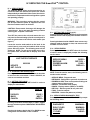
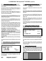
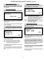
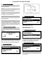
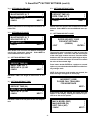
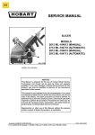
Traulsen Refrigeration
SERVICE MANUAL #02
Instructions For The Installation,
Troubleshooting And Repair Of Traulsen
SmartChillTM Equipped Blast Chiller Models
50 lb. Capacity Undercounter Models
100 lb. Capacity Reach-In Models
200 lb. Capacity Roll-In & Roll-Thru Models
-NOTICEThis Manual is prepared for the use of trained Authorized Traulsen Service Agents and should not be used
by those not properly qualified, nor should the equipment for which it is prepared be adjusted or repaired by
anyone except properly qualified personnel. This manual is not intended to be all encompassing, but is
written to supplement the formal training, on-the-job experience and other product knowledge acquired by
Authorized Traulsen Service Agents. Reproduction or other use of this Manual, without the express written
consent of Traulsen & Co., Inc. is prohibited.
FORM NUMBER TR????? - REV. 6/03
TABLE OF CONTENTS
I. THE SERIAL TAG
1
II. GENERAL INFORMATION
a-Introduction
b-Operation
c-Cleaning
d-Applicable Models
e-Wiring Diagrams
f-Tool Requirements
2
2
2
2
2
2
III. SPECIFICATIONS/OPERATING DATA
3
V. SmartChillTM FACTORY SETTINGS (cont’d)
k-Settings-Defrost INTVL
l-Settings-Security Code
m-Secure Settings-MACH. MODEL
n-Secure Settings-Machine Size
o-Secure Settings-Soft Freeze
p-Secure Settings-Freeze Max
q-Secure Settings-FRZ Min
r-Secure Settings-Defrost Type
s-Secure Settings-Saving Changes
t-Software Version
8
8
9
9
9
9
9
9
9-10
10
VI. CONTROLLER SERVICE PROCEDURES
IV. SERVICING THE SMART CHILLTM CONTROL
a-Service Mode
b-Updating The Service Date
c-Setting The Clock
d-Service Menu
e-Service Menu-Diagnostic Test
f-Service Menu-Refrigeration System/Air Flow Test
g-Service Menu-Probes/Alarms Test
h-Service Menu-Display Test
i-Service Menu-Door Test
j-Service Menu-Defrost System & Coil Probe Test
k-Service Menu-Fan Output Test
l-Service Menu-Printer Test
4
4
4
4
4-5
5
5
5-6
6
6
6
6
V. SmartChillTM FACTORY SETTINGS
a-Factory Settings Mode
b-Resetting The Serial Number
c-Settings-Back Door
d-Settings-Label Printer
e-Settings-Fans In HLD Cycle
f-Settings-Blasting DIFF
f-Settings-Holding DIFF
h-Settings-ANTI-SHORT
i-Settings-Defrost Time
j-Settings-Defrost Temp
7
7
7
7
7
7
8
8
8
8
a-Controller Board
b-I/O Board
c-Component Location
11
11
11
VII. COMPONENT FUNCTION
12
VIII. SEQUENCE OF OPERATION
a-Refrigeration System
b- IDLE Mode
c- Hold Mode
d-By Time Chill/Freeze Mode
e-By Temp Chill/Freeze Mode
f-By Product Chill/Freeze Mode
g-Defrost Mode`
13
13
13
13
13
14
14
IX. WIRING DIAGRAMS - RBC50 MODELS
15
X. WIRING DIAGRAMS - RBC100 MODELS
16
XI. WIRING DIAGRAMS - RBC200 MODELS
17
XII. TROUBLESHOOTING
18
I. THE SERIAL TAG
The serial tag is a permanently affixed sticker on which is
recorded vital electrical and refrigeration data about your
Traulsen product, as well as the model and serial number.
This tag is located on the left side of the interior compartment of all compact undercounter refrigerator, freezer and
prep table models.
FORT WORTH, TX.
SERIAL
VOLTS
MODEL
Hz
PH
TOTAL CURRENT
AMPS
MINIMUM CIRCUIT
AMPS
MAXIMUM OVERCURRENT PROTECTION
LIGHTS
WATTS
HEATERS
AMPS
AMPS
READING THE SERIAL TAG
REFRIGERANT
DESIGN PRESSURE
TYPE
HIGH
OZ
LOW
REFRIGERANT
DESIGN PRESSURE
TYPE
HIGH
OZ
LOW
• Serial = The permanent ID# of your Traulsen
• Model = The model # of your Traulsen
• Volts = Voltage
• Hz = Cycle
• PH = Phase
• Total Current = Maximum amp draw
• Minimum Circuit = Minimum circuit required
• Lights = Light wattage
• Heaters = Heater amperage
• Refrigerant = Refrigerant type used
• Design Pressure = High & low side operating
pressures and refrigerant charge
• Agency Labels = Designates agency listings
370-60294-00 REV (A)
R
R
AW-03118
-1-
II. GENERAL INFORMATION
II. f - TOOL REQUIREMENTS:
For most jobs a standard set of hand tools, a VOM
with AC current tester, electrically conductive field
service grounding kit (p/n TL84919), along with a temperature tester or thermometer are adequate. However in some cases the following additional tools may
be required as well:
II. a - INTRODUCTION:
Blast Chillers are food processing refrigerators designed for rapid chilling of product from 140 F to 40 F
in approximately 90 minutes, for reheating and/or serving at a later time.
These models aid in preserving food quality, texture
and nutritional value, in addition to enhancing food
safety.
•
•
•
•
•
•
•
All of the information, illustrations and specifications
contained within this manual are based on the latest
product information avaialble at the time of printing.
II. b - OPERATION:
Refer to the instructions contained in the Owner’s
Manual, form number TR35744, for specific operating
instructions.
II. c - CLEANING:
Detailed cleaning instructions are included with each
unit, however, special care MUST be given to the condenser coil(s). These must be cleaned WEEKLY. This
surface must be kept free of dirt and grease for proper
system operation. This can be done with a vacuum
cleaner using a brush attachment, or a stiff brush or
wisk broom. Care must be taken not to damage the
condenser coil fins. For more information please refer to section “IV. a - IV c” of the Blast Chill Owner’s
Manual.
II. d - APPLICABLE MODELS:
This manual applies to the following Traulsen models:
RBC50 Undercounter Blast Chiller Models
RBC100 Reach-In Blast Chiller Models
RBC200 Roll-In Blast Chiller Models
RBC200RT Roll-Thru Blast Chiller Models
PLEASE NOTE: This manual refers to the above models built after June 2003, equipped with the SmartChillTM
control. For information regarding models built prior
to that date please contact the factory.
In addition, models UBC50, RBC400 and RBC400RT
are not covered by the procedures listed in this manual.
Please contact the factory for more information.
II. e - WIRING DIAGRAMS:
Refer to the wiring diagrams on pages ?? thru ?? for
any service work performed on the unit. Should you
require another copy, please contact Traulsen Service
at (800) 825-8220, and provide the model and serial
number of the unit involved.
-2-
Refrigeration Reclaiming Equipment
Acetylene Torch
Nitrogen Bottle With Gauges
Refrigeration Gauge Manifold
Dial-a-change
Valve Core Removal Kit
Vacuum Pump
III. SPECIFICATIONS/OPERATING DATA
DATA
H.P.1
BTU1
H.P.2
BTU2
Refrigerant1
Refrigerant2
Refrigerant Charge1
Refrigerant Charge2
Cond Unit Amp Draw (RLA)1
Cond Unit Amp Draw (RLA)2
Evap Fans Amp Draw (RLA)
Unit Voltage
Full Load Amps
RBC50
1/2 HP
1350
1/2 HP
1350
R-404A
R-404A
20 oz.
20 oz.
RBC100
1/2 HP
2280
1-1/4 HP
5460
R-404A
R-404A
49 oz.
92 oz.
RBC200
3/4 HP
3880
n/a3
n/a3
R-404A
n/a3
20 oz.
n/a3
RBC200RT
3/4 HP
3880
n/a3
n/a3
R-404A
n/a3
20 oz.
n/a3
115/60/1
18.6
220/115
15.1
115/60/11 115/60/11
15.21
15.21
1= Self-Contained Holding or Primary Compressor.
2= Blast Chilling or Secondary Compressor.
3= These may vary depending upon type of remote condensing unit selected.
DIMENSIONS
Length - Overall in.
Depth - Overall in.
Height - Overall in.
RBC50
57-1/2
34-1/4
341
RBC100
34
41-5/8
80-1/8
RBC200
48-1/2
37-1/2
89-1/2
RBC200RT
48-1/2
41-1/8
89-1/2
1= Height shown to work top, height over control is 53”.
Model: RBC50
Refrigerant
R-404A
Ambient Temperature
70° F
Suction Presure (chill mode)
Start of Cycle
End of Cycle
Suction Presure (freeze mode)
Start of Cycle
End of Cycle
Discharge Pressure PSIG
Start of Cycle
End of Cycle
Model: RBC100
Refrigerant
R-404A
Ambient Temperature
70° F
Suction Presure (chill mode)
Start of Cycle
End of Cycle
Suction Presure (freeze mode)
Start of Cycle
End of Cycle
Discharge Pressure PSIG
Start of Cycle
End of Cycle
Model: RBC200 & RBC200RT
Refrigerant
R-404A
Ambient Temperature
70° F
Suction Presure (chill mode)
Start of Cycle
End of Cycle
Suction Presure (freeze mode)
Start of Cycle
End of Cycle
Discharge Pressure PSIG
Start of Cycle
End of Cycle
R-404A
100° F
R-404A
100° F
-3-
R-404A
100° F
IV. SERVICING THE SmartChillTM CONTROL
IV. a - SERVICE MODE:
The SERVICE MODE allows service personnel to exercise the loads and monitor the input of the control
independently to deterfmine if the control, the electromechanical components and the refrigeration system
are operating properly.
WARNING: This procedure requires that the control
box be open while the power is supplied to the unit.
Exercise extreme caution at all times.
CAUTION: Electro-static discharge will damage the
control board. Use a anti-static grounding kit when
servicing the computer control box.
(figure 1)
IV. c - SETTING THE CLOCK (cont’d):
Pressing the button beside ENTER saves the new date
and time selected and displays the last date of service
menu.
Turn OFF the power to the unit, and remove the control panel screws and swing open the control panel in
order to gain access to the service mode switch (see
figure 1).
Pressing the button beside CANCEL does not save any
changes made to the date or time, and returns to the
last date of service menu.
Locate the service mode switch on the back of the
control board, press and hold switch while turning
power ON to the chiller. The following menu will be
displayed. NOTE: To exit service mode at any time,
turn power OFF and back ON to display user main
menu.
IV. d - SERVICE MENU:
Pressing the button beside NEXT when the last date
of service menu is displayed prompts the following
service menu:
LAST DATE OF SERVICE
<
<
<
<
00/00/00
< UPDATE
< SET CLOCK
NOTE: From the service menu, the following servcie
modes can be selected:
• SERVICE MENU - Diaganostic test
• REFRN/AIR - Refrigeration system & air probe test
• PROBES/ALARM - View current probes reading and
change status of alarm output
• DISPLAY - Illuminates entire display
• DOORS - Displays status (OPEN or CLOSED)
• DEF/COIL - Defrost system & coil probe test
• FANS - Tests fan outputs
• PRINTERS - Sends test pattern to printer(s)
IV. c - SETTING THE CLOCK:
Pressing the button beside SET CLOCK in order to
display the menu below.
⇓ XX/XX/XX
< BACK
< CANCEL
DOOR >
DEF/COIL >
FANS >
DISPLAY >
NEXT >
IV. b - UPDATING THE SERVICE DATE:
Pressing the button beside UPDATE sets the last date
of service to the current date. If date is INVALID, set
clock to current date and time.
SET CLOCK
SERVICE MENU
REFR/AIR
PROBES/ALARM
PRINTER
MONTH
XX:XX ⇑
NEXT >
ENTER >
IV. e - SERVICE MENU-DIAGNOSTIC TEST:
Pressing the button beside SERVICE MENU prompts
the following menu:
Pressing the buttons beside BACK or NEXT toggles
through selection options: MONTH/DAY/YEAR/HOUR/
MINUTE.
< DIAGNOSTIC
< RUN CYCLES
< SINCE DEF.
CYCLES
Pressing the buttons beside the UP or DOWN arrows
changes the selected date or time numbers.
-4-
MAXIMUM >
MINIMUM >
FAILURE >
CLEAR >
IV. SERVICING THE SmartChillTM CONTROL (cont’d)
IV. e - SERVICE MENU-DIAGNOSTIC TEST (cont’d):
Pressing the button beside DIAGNOSTIC returns to the
service menu.
IV. f - SVCE MENU-REF’N SYSTEM/AIR PROBE TEST (cont’d):
ON&FANS = Refrigeration and evaporator fans
operational.
Pressing the button beside RUN CYCLES displays (in
the lower left corner of the display) the number of
cycles ran since last cleared.
The current air temperature inside the cavity is also
displayed.
The service menu can be accessed by pressing the
button beside BACK, and all outputs will return to their
OFF state.
Pressing the button beside SINCE DEF displays (in
the lower left corner of the display) the number of
cycles ran since last defrost.
Pressing the button beside COMP USAGE displays the
days and hours since the last cleaning of the condenser coil.
Pressing the button beside MAXIMUM displays (in the
lower left corner of the display) the maximum air temperature of the cabinet.
NOTE: After cleaning the condenser coil, press the
button beside CLEANED COIL to reset the day and hour
for both to read “0”.
Pressing the button beside MINIMUM displays (in the
lower left corner of the display) the minimum air temperature of the cabinet.
The previous menu can be accessed by pressing the
button beside BACK, and all outputs will return to their
OFF state.
Pressing the button beside FAILURE displays (in the
lower left corner of the display) the failure since last
service cleared. If there is more than one failure, pressing the lower elft button will cycle through all the failure. Below is a complete list of all possible failures:
IV. g - SERVICE MENU-PROBES/ALARM TEST:
From the service menu, pressing the button beside
PROBES/ALARM prompts the following menu:
DEFR HEAT = Defrost Heater Malfunction.
SYSTEM FAIL = Chiller Not Cooling Properly.
OVER TEMP = Internal Air Temperature Exceeds 150°F.
CONTROL = Control Board Malfunction.
INTERRUPTED = A Chilling Cycle Has Been Interrupted
Either By Loss Of Main Power Or By Inadvertently
Switching Power OFF.
PROBE = One Of The Probes Have Malfunctioned: Air,
Coil or Product.
PRINTER = Printer Not Responding Or Out Of Paper/
Label.
This screen displays the value of each product probe.
If no value(s) shown find the source of the problem.
Pressing the button beside CLEAR clears the current
item.
The alarm output can also be changed from OFF to
ON.
IV. f - SERVICE MENU-REF’N SYSTEM & AIR PROBE TEST:
From the service menu, pressing the button beside
REFN/AIR prompts the following menu:
The service menu can be accessed by pressing the
button beside BACK, and the alarm output will return
to the OFF state.
REFRIGERATION TEST:
< REFN: OFF
AIR TEMP:
< COMP USAGE
PRODUCT PROBE TEMPS:
1 74°F
2 73°F
< ALARM = OFF
BACK >
IV. h - SERVICE MENU-DISPLAY TEST:
From the service menu, pressing the button beside
DISPLAY illuminates the entire display (see below).
Pressing any key will return the display to the service
menu. This option can also be used as a test for the
keypad, since any key press will return to the previous menu.
14°F
BACK >
Pressing the button beside REFN can test the compressor function. The options for REFN are: OFF, ON,
and ON&FANS.
OFF =
ON =
73°F 3
Refrigeration not operational
Refrigeration operational
-5-
IV. SERVICING THE SmartChillTM CONTROL (cont’d)
IV. h - SERVICE MENU-DISPLAY TEST (cont’d):
NOTE: If the screen does not display as shown above
the display board needs to be replaced. If display does
not return to the service menu then the keypad needs
to be replaced.
IV. k - SERVICE MENU-FAN OUTPUT TEST:
From the service menu, pressing the button beside
FANS displays the fan output test. The options for
fans are: NONE, SET 1, SET2 and BOTH.
IV. i - SERVICE MENU-DOOR TEST:
From the service menu, pressing the button beside
DOORS displays the door status (OPEN or CLOSED).
FAN MODE TEST:
<
FAN = NONE
FAN DOOR = CLOSED
BACK >
DOOR INPUTS:
NONE = All evaporator fans de-energized.
SET 1 = This is the low air flow mode for soft chill
mode. Only one evaporator fan is energized.
If not find the source of the problem.
SET 2 = Two evaporator fans energized. If not find
the source of the problem.
BOTH = All evaporator fans energized. If not find the
source of the problem.
OPEN/CLOSED
BACK >
NOTE: Cycling the door OPEN and CLOSED shows
the status of the the unit door(s). If not find the source
of the problem.
IV. l - SERVICE MENU-PRINTER TEST:
From the service menu, pressing the button beside
PRINTERS displays the printer test menu - this sends
a test print to the printer(s).
The service menu can be accessed by pressing the
button beside BACK.
IV. j - SVCE MENU-DEFROST SYSTEM & COIL PROBE TEST:
From the service menu, pressing the button beside
DEF/COIL displays the defrost system and coil probe
test.
DEFROST TEST:
< HEATER = OFF
COIL TEMP = 76°F
PRINTER TEST:
< RECORD: READY
< LABEL:
READY
BACK >
BACK >
NOTE: “LABEL: READY” will not appear on the display if the optional label printer is not included with
the particular unit.
The defrost heat can be turned OFF or ON by pressing
the button beside HEATER.
Pressing the button beside RECORD sends a test print
out to the standard paper prtinter. The “READY” on
the display will change to “RUNNING”, then to “SUCCESS” if the print completes successfully. Otherwise
“ERROR” will appear on the display, prompting you
to locate the source of the problem.
OFF = Defrost heater should not be energized.
ON = Defrost heater should energize and coil
temperature should slowly increase.
The coil temperature is also displayed. If not find the
source of the problem.
If the optional label printer is installed, the label test
print can be run by pressing the button beside LABEL
to send out a test print.
The service menu can be accessed by pressing the
button beside BACK. Doing so also turns the heater
OFF.
The service menu can be accessed by pressing the
button beside BACK.
-6-
V. SmartChillTM FACTORY SETTINGS
V. a - FACTORY SETTINGS MODE:
The FACTORY SETTINGS MODE allows service personnel to return various control settings to their factory preset parameters.
WARNING: This procedure requires that the control
box be open while the power is supplied to the unit.
Exercise extreme caution at all times.
CAUTION: Electro-static discharge will damage the
control board. Use a anti-static grounding kit when
servicing the computer control box.
(figure 2)
Turn OFF the power to the unit, and remove the control panel screws and swing open the control panel in
order to gain access to the factory settings mode
switch (see figure 2).
V. d - SETTINGS-LABEL PRINTER:
⇓ BACK DOOR (NO)
⇓ LABEL PRINTER (NO)
⇓ FAN IN HLD (CYCLE)
< RESET
Locate the factory settings mode switch on the back
of the control board, press and hold switch while turning power ON to the chiller. The following menu will
be displayed. NOTE: To exit factory settings mode at
any time, turn power OFF and back ON to display user
main menu.
LABEL PRINTER options are:
V. b - RESETTING THE SERIAL NUMBER:
To enter the serial number, press the button beside
S/N, which changes the digit to edit, and then use the
UP arrow to increment the value of the selected digit
from 0-9.
OFF = No label printer installed.
ON = Individual labels.
V. e - SETTINGS-FANS IN HLD CYCLE:
⇓ BACK DOOR (NO)
⇓ LABEL PRINTER (NO)
⇓ FAN IN HLD (CYCLE)
< RESET
FACTORY SETTINGS
VERSION:
<
S/N:
< RESET
⇑
⇑
⇑
NEXT >
NEXT >
⇑
⇑
⇑
NEXT >
RESET - Resets all the parameters to the factory preset values, and erases all recorded cycles in memory.
Fans are defaulted to cycle ON and OFF. Select (CONT)
for continuous fan operation during hold mode. Select NEXT to access additional menu options.
NEXT - Continues to the next factory settting menu.
V. f - SETTINGS-BLASTING DIFF:
V. c - SETTINGS-BACK DOOR:
BACK DOOR is not an option, select NO.
⇓ BACK DOOR (NO)
⇓ LABEL PRINTER (NO)
⇓ FAN IN HLD (CYCLE)
< RESET
⇓ BLASTING DIFF (4) °F
⇓ HOLDING DIFF (4) °F
⇓ ANTI-SHORT (3)
< BACK
⇑
⇑
⇑
NEXT >
⇑
⇑
⇑
NEXT >
Blasting differential is the temperature difference between set point temperature and the actual temperature for opening the compressor solenoid when in chill
or freeze mode.
-7-
V. SmartChillTM FACTORY SETTINGS (cont’d)
V. g - SETTINGS-HOLDING DIFF:
⇓ BLASTING DIFF (4) °F
⇓ HOLDING DIFF (4) °F
⇓ ANTI-SHORT (3)
< BACK
V. k - SETTINGS-DEFROST INTVL:
⇓ DEFROST TIME (20)
⇓ DEFR. TEMP (50) °F
⇓ DEFR. INTVL (6) HR
< BACK
⇑
⇑
⇑
NEXT >
Holding differential is the temperature difference for
hold mode.
⇑
⇑
⇑
NEXT >
Defrost interval is the time interval between automatic
defrosts. Select NEXT to access additional menu options.
V. h - SETTINGS-ANTI-SHORT:
V. l - SETTINGS-SECURITY CODE:
⇓ BLASTING DIFF (4) °F
⇓ HOLDING DIFF (4) °F
⇓ ANTI-SHORT (3)
< BACK
⇑
⇑
⇑
NEXT >
ENTER SECURITY CODE
FOR NEXT SETTINGS:
<
(0000000)
⇑
< EXIT
ENTER >
ANTI-SHORT is the minimum time between closing and
opening the compressor solenoid. Select NEXT to
access additional menu options.
The security code is required in order to access the
additional options. The code is the last seven digits
of the units serial number reversed. Press the button
beside the LEFT arrow to select whch digit to adjust,
and then the button beside the UP arrow to increment
the value of the selected digit.
V. i - SETTINGS-DEFROST TIME:
⇓ DEFROST TIME (20)
⇓ DEFR. TEMP (50) °F
⇓ DEFR. INTVL (6) HR
< BACK
⇑
⇑
⇑
NEXT >
Press button beside ENTER to continue to secured
options or press the button beside EXIT to exit the factory settings mode.
NOTE: If the incorrect serial number was entered, the
below message will appear on the display.
DEFROST TIME is the length of defrost time in minutes.
INCORRECT CODE!
PLEASE CALL TRAULSEN
FOR ASSISTANCE
NEXT >
V. j - SETTINGS-DEFROST TEMP:
⇓ DEFROST TIME (20)
⇓ DEFR. TEMP (50) °F
⇓ DEFR. INTVL (6) HR
< BACK
⇑
⇑
⇑
NEXT >
If the correct code was entered, the below menu will
appear on the display, allowing the servicer to proceed on to the secure options.
DEFROST TEMP is the set point for the coil temperature.
⇓ MACH. MODEL (RBC)
⇓ MACHINE SIZE (50)
⇓ SOFT CHILL (NO)
< BACK
-8-
⇑
⇑
⇑
NEXT >
V. SmartChillTM FACTORY SETTINGS (cont’d)
V. q - SECURE SETTINGS-SFT FRZ MIN:
V. m - SECURE SETTINGS-MACH.MODEL:
⇓ MACH. MODEL (RBC)
⇓ MACHINE SIZE (50)
⇓ SOFT FREEZE (NO)
< BACK
⇓ FREEZE MAX (20) °F
⇓ SFT FRZ MIN (-5) °F
⇓ DEFROST TYPE (ELE)
< BACK
⇑
⇑
⇑
NEXT >
⇑
⇑
⇑
NEXT >
SFT FRZ MIN is the minimum selectable value for SOFT
CHILL mode for all chiller models.
MACH. MODEL is not an option, select NO.
V. n - SECURE SETTINGS-MACHINE SIZE:
V. r - SECURE SETTINGS-DEFROST TYPE:
⇓ MACH. MODEL (RBC)
⇓ MACHINE SIZE (50)
⇓ SOFT FREEZE (NO)
< BACK
⇑
⇑
⇑
NEXT >
⇓ FREEZE MAX (20) °F
⇓ SFT FRZ MIN (-5) °F
⇓ DEFROST TYPE (ELE)
< BACK
MACHINE SIZE is the distinction, in capacity, between
the different model/size blast chillers, either 50, 100 or
200. Do not select any other size than actual chiller
size.
⇑
⇑
⇑
NEXT >
DEFROST TYPE is selection for chiller to defrost by
(GAS) on RBC50 models and (ELE) for all other models. Press the button beside NEXT to exit factory settings.
V. o - SECURE SETTINGS-SOFT FREEZE:
V. s - SECURE SETTINGS-SAVING CHANGES:
⇓ MACH. MODEL (RBC)
⇓ MACHINE SIZE (50)
⇓ SOFT FREEZE (NO)
< BACK
⇑
⇑
⇑
NEXT >
FACTORY SETTINGS
DO YOU WISH TO SAVE
THESE NEW SETTINGS?
< NO
SOFT FREEZE is not an option, select NO. Select NEXT
to access additional menu options.
YES >
Upon selecting NEXT, the above menu should be displayed.
V. p - SECURE SETTINGS-FREEZE MAX:
⇓ FREEZE MAX (20) °F
⇓ SFT FRZ MIN (-5) °F
⇓ DEFROST TYPE (ELE)
< BACK
YES - Saves the new settings to memory.
NO - Exits Factory Settings without saving changes.
⇑
⇑
⇑
NEXT >
Upon selecting YES (save changes) the below message will appear on the display.
SAVING SETTINGS
FREEZE MAX is the maximum selectable value for
freezing in FREEZE CHILL mode for all chiller models.
PLEASE WAIT...
-9-
V. SmartChillTM FACTORY SETTINGS (cont’d)
V. s - SECURE SETTINGS-SAVING CHANGES (cont’d):
When the new settings have been saved the below
message will be displayed.
FACTORY SETTINGS
SETUP IS COMPLETE!
RESTART CONTROLLER
V. t - SOFTWARE VERSION:
The control program software version is diaplyed during initialization whenever the unit is turned ON. The
display will show the chiller model number and the
current software version number as shown below.
SMART CHILL
RBC50
INITIALIZING
VERSION: X.XX
-10-
VI. CONTROLLER SERVICE PROCEDURES
VI. a - CONTROLLER BOARD:
The controller has two LED’s to assist in troubleshooting. LED (D2 POWER) is illuminated indicating that
power is supplied to the controller board. LED (D1)
flashes indicating that the I/O board and control board
are communicating. If not, check all harness connections to the communications cables going between the
I/O and controller boards. LED (D13) is not used.
VI. c - COMPONENT LOCATION:
POWER STRIP
OVERTEMP
THERMOSTAT
I/O BOARD
EVAPORATOR FANS
CAPACITORS (3)
VI. b - I/O BOARD:
The I/O board has a series of LED’s and test points to
assist in troubleshooting. When the LED is illuminated,
the component should be energized or input open.
TRANSFORMER
POWER
SUPPLY
BOARDS (2)
PRINTERS
CONTROLLER
LED
D1
D2
D3
D4
D8
D9
D10
D11
TEST
POINT
TP1
TP2
TP3
J17, J18
J15, J16
COMPONENT
Front Door
Not Used
Fan Door
Compressor Solenoid
Defrost Heater
Low Fan
High Fan
Alarm
COMPONENT
VOLTAGE
POWER
SWITCH
SAFETY
THERMOSTAT
BULB
DEFROST
HEATER
FAN DOOR
SWITCH
COIL-TEMP
SENSOR
EVAPORATOR
FAN MOTOR (3)
AIR-TEMP
SENSOR
+12VDC
+5VDC
0V
0.75 - 2VAC
Voltage Drop
0.75 - 2VAC
Voltage Drop
EXPANSION
VALVE
DEFROST
HEATER
DEFROST
HEATER
EXPANSION
VALVE BULB
DUAL
PRESSURE
SWITCH
THERMAL
OVERLOAD
RUN
CAPACITOR
RELAY
Relays
Logic Circuit
Ground
Triac Compressor
Solenoid
Triac Defrost
Heater
POWER
SWITCH
START
CAPACITOR
COMPRESSOR
CONDENSER
FAN MOTOR
FRONT VIEW
SOLENOID
VALVE
SIGHT GLASS
FILTER DRIER
BACK VIEW
-11-
HOT GAS
CONDENSATE
EVAPORATOR
VII. COMPONENT FUNCTION
Compressor
Condenser Fan
Dual Pressure Control
Start Capacitor
Run Capacitor
Thermal Overload
Relay
Evaporator Fan
Defrost Heater
Air Temperature Sensor
Coil Temperature Sensor
Food Temperature Probe
Front Door Switch
Fan Door Switch
Solenoid Valve
Door Perimeter Heater
Door Heater Thermostat
Controller
Power Supply Boards
I/O Board
Main Contactor
Main Switch
Over Temp. Thermostat
(manual reset)
Safety Thermostat
(manual reset)
Pumps refrigerant through refrigeration lines and components.
Draws air across condenser coil to aid in removing heat from the refrigerant and
moves air across compressor to aid in cooling the compressor.
Low side monitors suction pressure at compressor. Shuts compressor OFF when
low pressure setting is reached (cut-out). Allows compressor to run when pres
sure rises to cut-in setting.
High side monitors discharge pressure at compressor. Shuts compressor OFF
when high side pressure setting is reached (cut-out). Allows compressor to run
when pressure returns to cut-in setting.
The differential is the difference in pressure between open and closed states of the
pressure switch.
Wired in series with the start windings to help start compressor motor.
Continually in circuit to help compressor motor during operation.
Removes power from compressor if the internal temperature of the compressor
becomes too high (auto reset).
Senses current of run winding of compressor motor. Normally open contacts
close when run winding draws a high amperage at start and brings the start
capacitor and start windings into the circuit. As the motor reaches operating
speed (less amperage through run winding), the normally open contacts open and
removes the start capacitor and start windings from the circuit.
Draws air from the cabinetand moves air through the evaporator coil. Air should
blow toward the door.
Defrosts evaporator coil and prevents water droplets from evaporator coil from
freezing before they can drain to the condensate pan. Operates only during
defrost cycle.
Monitors air temperature inside the cabinet.
Monitors the scution line temperature at evaporator during defrost cycle.
Monitors temperature of food product.
Monitors door for open or closed position. Evaporator fans stop when door is
open.
Monitors evaporator fan compartment door for open or closed position.
Evaporator fans will not start if the switch is open. Refrigerant system operation
stops after 30 seconds switch has been open.
Normally closed. When energized, allows refrigerant to flow to flow from receiver
to evaporator coil.
Prevents condensate on door frame.
Monitors door frame temperature. Opens circuit to door frame heater if the door
frame temperature exceeds set point.
Performs the following functions:
a) Displays all data for the current mode of operation.
b) Cycles refrigeration system to maintain cabinet temperature.
c) Monitors power failures.
d) Monitors door position.
Controls power to I/O board and printers.
Performs the following functions:
a) Cycles defrost heaters during defrost cycle.
b) Cycles compressor solenoid to maintain cabinet temperature.
c) Monitors AC monitor to determine loss of power.
d) Closes alarm contact to signal external alarm device, after a malfunction detected.
e) Monitors door switch position.
f) Monitors fan door switch.
Controls power to unitelectrical circuits once main switch is closed.
Controls power to main contactor when safety thermostat is closed. Removes
power from all components including the controller.
Monitors cabinet air temperature. Opens circuit to main contactor if cabinet
temperature exceeds 155°F.
Monitors cabinet air temperature. Opens circuit to main contactor if cabinet
temperature exceeds 155°F.
-12-
VIII. SEQUENCE OF OPERATION
VIII. a - REFRIGERATION SYSTEM:
1. The controller must be in a chill or hold mode.
2. The controller monitors the air temperature and
senses a need for cooling.
a) The relay that controls the solenoid valve is
energized.
1-Solenoid valve is energized and refrigerant
flows to the evaporator.
3. The low pressure switch closes with the rise in
pressure.
a) The compressor motor is energized and
refrigerant is pumped through the system.
4. The expansion valve monitors the evaporator
superheat and meters the amount of refrigerant
entering the evaporator.
5. The controller senses the air temperature
requirements have been met.
a) De-energizes the relay that controls the
solenoid valve.
1-Solenoid valve is de-energized and closes.
Refrigerant flow to the evaporator stops.
6. Compressor continues to run. Low pressure
control opens as pressure drops.
a) Compressor motor de-energized.
7. Unit is cycled by controller.
VIII. c - HOLD MODE (cont’d):
factory setup menus.
NOTE: If the cabinet door is opened during
operation, the evaporator fans and refrigeration
system will shut down.
b) The hold mode has an automatic defrost
cycle after a programable interval of
operation in the hold mode.
1-When the defrost cycle is complete and the
unit returns to the hold mode, the
evaporator fans will not operate until the
coil temperature is below 25°F.
3. Hold mode is terminated by pressing the exit key.
NOTE: If the HOLD MODE is terminated by the
operator with the deforst cycle in progress, the
defrost mode will continue until completion before
going into idle mode.
VIII. d - BY TIME CHILL OR FREEZE MODE:
1. Unit is in IDLE mode.
2. Chill type is selected and a cycle time is entered
then start key is pressed.
3. The refrigeration system will cycle on the
blasting air temperature set-point.
a) ON at the set-point plus differentia.
b) OFF when set-point is reached.
4. If SOFT CHILL has been selected, the
refrigeration system will cycle on the new
blasting air temperature set-point. If CHILL was
selected, the set-point remians the same until
the end of the cycle.
NOTE: If the cabinet door is opened during
operation, the evaporator fans and refrigeration
system will shut down.
5. Chill mode is terminated when time expires.
a) Buzzer sounds until muted.
6. At the end of a chill cycle the unit will enter the
hold mode.
a) If the end of the chill cycle is acknowledged
by pressing the STOP/RESET key, the unit
will enter the idle mode.
VIII. b - IDLE MODE:
1. Conditions
a) Unit connected to correct voltage.
b) Safety thermostat closed.
c) Fan door switch closed.
d) Front door switch closed.
2. Main switch closed.
a) Main contactor energized, contacts close.
1-Door heater energized.
2-Controller energized.
3-Power to condensing unit controls.
3. Controller goes through power up selfdiagnostics and displays main menu.
VIII. c - HOLD MODE:
Product can be held at chilled temperature by
selecting hold mode from main menu. Unit will also
go into hold mode automatically when all active
probes have reached the target temperature when in
“BY TEMP” mode. If a “BY TIME” mode is slected,
the unit enters hold mode automatically after the
time has expired.
1. Unit is in IDLE mode.
2. Hold mode is selected.
NOTE: When the hold mode is selected, two timers
run. One tracks the time in the hold mode and the
other tracks the time since the last defrost (hold
mode defrosts at a programable interval).
a) The refrigeration system will cycle on the air
temperature of the cabinet.
1-ON at the set-point plus differential.
2-OFF when set-point reached.
NOTE: Set-point and differential are selected in the
VIII. e - BY TEMP CHILL OR FREEZE MODE:
1. Unit is in IDLE mode.
2. Chill type is selected and a target teperature is
entered then start key pressed and probe
selected.
3. The refrigeration system will cycle on the
blasting air temperature set-point.
NOTE: If the cabinet door is opened during BY TEMP
chill operation, the evaporator fans and refrigeration
system will shut down.
4. Chill mode is terminated when all the product
probes reach the target chill temperature.
NOTE: Once the temperature of the probe reaches
the target temperature the display will alternate with
“DONE”, and the buzzer will sound unless muted.
a) At the end of the chill cycle the unit will enter
idle mode.
-13-
VIII. SEQUENCE OF OPERATION (cont’d)
VIII. f - BY PRODUCT CHILL OR FREEZE MODE:
1. Unit is in IDLE mode.
2. Product type is selected.
3. Chill type is selected and a target teperature is
entered then start key pressed and probe
selected.
4. The refrigeration system will cycle on the
blasting air temperature set-point.
NOTE: If the cabinet door is opened during
operation, the evaporator fans and refrigeration
system will shut down.
5. Chill mode is terminated when all the product
probes reach the target chill temperature.
NOTE: Once the temperature of the probe reaches
the target temperature the display will alternate with
“DONE”, and the buzzer will sound unless muted.
a) At the end of the chill cycle the unit will enter
idle mode.
VIII. g - DEFROST MODE:
1. The defrost mode can be entered manually from
the idle mode or automatically from the hold
mode.
2. Defrost cycle length is by set minutes or until the
coil temperature reaches set-point.
NOTE: Minutes and coil temperature are adjustable
in the Factory Settings mode.
a) If the defrost mode was entered from the
hold mode, the unit will return to the hold
mode.
-14-
IX. WIRING DIAGRAM - RBC50 MODELS
-15-
X. WIRING DIAGRAM - RBC100 MODELS
-16-
XI. WIRING DIAGRAM - RBC200 MODELS
-17-
XII. TROUBLESHOOTING
WARNING: CERTAIN PROCEDURES IN THIS SECTION REQUIRE ELECTRICAL AND REFRIGERATION SYSTEM TEST OR MEASUREMENTS WHILE POWER IS APPLIED TO THE MACHINE. EXERCISE EXTREME CAUTION AT ALL TIMES. IF TEST POINTS ARE NOT EASILY ACCESSIBLE, DISCONNECT POWER, ATTACH TEST
EQUIPMENT AND REAPPLY POWER TO TEST.
-18-
Traulsen
4401 Blue Mound Road Fort Worth, TX 76106
Phone: (800) 825-8220 Fax-Svce: (817) 740-6757
Website: www.traulsen.com
Quality Refrigeration
HOURS OF OPERATION:
Monday thru Friday 7:30 am - 4:30 pm CST