1
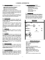
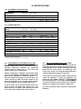
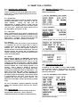
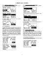
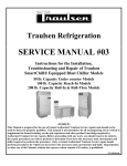
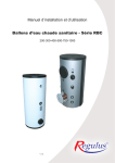
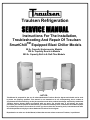
Traulsen Refrigeration SERVICE MANUAL Instructions For The Installation, Troubleshooting And Repair Of Traulsen TM SmartChill Equipped Blast Chiller Models 50 lb. Capacity Undercounter Models 100 lb. Capacity Reach-In Models 200 lb. Capacity Roll-In & Roll-Thru Models -NOTICEThis Manual is prepared for the use of trained Authorized Traulsen Service Agents and should not be used by those not properly qualified. This manual is not intended to be all encompassing, but is written to supplement the formal training, on-the-job experience and other product knowledge acquired by Authorized Traulsen Service Agents. Before proceeding with any work, you should read, in its entirety, the repair procedure you wish to perform to determine if you have the necessary tools, instruments and skills required to perform the procedure. Procedures for which you do not have the necessary tools, instruments and skills should be performed only by a trained Authorized Traulsen Service Agent. Reproduction or other use of this Manual, without the express written consent of Traulsen, is prohibited. -0- I. TABLE OF CONTENTS I. II. TABLE OF CONTENTS GENERAL INFORMATION a- Applicable Models b-Introduction c- Operation d-Cleaning e-Wiring Diagrams f-Tool Requirements g-The Serial Tag III. SPECIFICATIONS a-Equipment Specifications b-Operating Data IV. c-Installation SMART CHILL CONTROL a-Sequence of Operation a.1 Control Revision Numbers a.2 System Idle a.3 Chill Cycle a.4 Holding a.5 Defrost b-Manual Defrost c-Printing Control Data c.1 Cycle/Batch Data c.2 12 Hr Data Log d-SERVICE MENU ACCESS d.1 Introduction d.2 Access Service Menu (75) d.3 Access Service Menu (Push Button) f-SERVICE MENU NAVIGATION f.1 Refrigeration Test (REFR/AIR) f.2 Probe & Alarm Test (PROBES/ALARM) f.3 Printer(s) Test (PRINTER) f.4 Defrost Test (DEF/COIL) f.5 Evaporator Fan Test (FAN) f.6 Display LED Test (DISPLAY) g-DIAGNOSTICS MENU g.1 Accessing the Diagnostics Menu g.2 Using the Diagnostics Menu h-FACTORY MENU ACCESS h.1 Introduction h.2 Accessing the Factory Menu (85) h.3 Accessing the Factory Menu (Push Button) i-NAVIGATING THE FACTORY MENU i.1Reset and Serial Number Entry i.2 Printer Selection i.3 Refrigeration Settings i.4 Defrost Settings i.5 Security Code Entry i.6 Machine Size Selection 1 2 2 2 2 2 2 2 2 3 3 3 3 4 4 4 4 4 4 4 4 4 4-5 5 5 5 5-6 6 6 6-7 7 7-8 8 8 8-9 9 9 9 9 9 9-10 j-ERROR CODES j.1 Current Probe is Bad j.2 Chill Time Exceeded j.3 Defrost Sensor Failure j.4 No Product Probes j.5 Over Temperature j.6 Product Detected j.7 Air Temp Sensor Not Reading j.8 Record Printer Media j.9 Label Printer Media V. CONTROL COMPONENTS a-COMPONENT IDENTIFICATION & OPERATION a.1 Control /Relay Box a.2 Relay Board a.3 Power Supply a.4 Smart Chill Control (Mother Board) a.5 Control/Relay Box RBC50 2008 – Current a.6 Relay Board RBC50 2008-Current VI. SERVICE PROCEDURES RBC50 a. Indentify 2008 – Current vs Pre 2008 b. Sensors & Probes b.1 Air & Coil Sensor Locations RBC50 (pre 2008) b.2 Air & Coil Sensor Locations RBC50 (2008 – Current) b.3 Sensor & Probe Troubleshooting c. RBC50 Power Pack Removal (Pre 2008) d. RBC50 Evaporator Access (Pre 2008) e. RBC50 Evaporator Access (2008 – Current) VII. SERVICE PROCEDURES RBC100 a. Sensors & Probes a.1 Air & Coil Sensor Locations RBC100 a.2 Sensor & Probe Troubleshooting b. Access Evaporator/Refrig Sys b.1 RBC100 Exploded View b.2 Accessing the Evaporator Sensors b.3 Access the Evaporator, Defrost Heater & Thermal Fuse b.4 Remove Refrigeration System VIII. SERVICE PROCEDURES RBC200 a. Sensors & Probes a.1 Air & Coil Sensor Locations RBC200 a. 2 Sensor & Probe Troubleshooting b. RBC200 Evaporator Access 10 10 10 10 10 11 11 11 IX. X. XI. XII. XIII. XIV. XV. -1- WIRE DIAGRAM RBC50 2008-CURRENT WIRE DIAGRAM RBC50 2003-2007 WIRE DIAGRAM RBC100 WIRE DIAGRAM RBC200 TROUBLESHOOTING QUICK REFERENCE GUIDE DATA LOG DIAGNOSTICS 11 11 11 11-12 12 12 12 12 12 12 13 13 13 14 15 16 17 18 19 19 19 19 19 19 19 20 20 20 20 20 20 20 20 20 20 21 21 21 21 21 21 22 23 24 25 26-30 31 32 II. GENERAL INFORMATION II. a - APPLICABLE MODELS: This manual applies to the following Traulsen models: II.f - TOOL REQUIREMENTS (CONT): • • • • • • • RBC50 Undercounter Blast Chiller Models RBC100 Reach-In Blast Chiller Models RBC200 Roll-In Blast Chiller Models RBC200RT Roll-Thru Blast Chiller Models PLEASE NOTE: This manual refers to the above models built after June 2003, equipped with the Smart Chill control. For information regarding models built prior to that date please contact the factory. Refrigeration Reclaiming Equipment Acetylene Torch Nitrogen Bottle With Gauges Refrigeration Gauge Manifold Dial-a-Charge Valve Core Removal Kit Vacuum Pump II. g - THE SERIAL TAG: The serial tag is a permanently affixed sticker on which is recorded vital electrical and refrigeration data about your Traulsen product, as well as the model and serial number. This tag is located at the front top corner on the right interior wall on all blast chiller models. An example is shown below. In addition, models UBC50, RBC400 and RBC400RT are not covered by the procedures listed in this manual. Please contact the factory for more information. II. b - INTRODUCTION: Blast Chillers are food processing refrigerators designed for rapid chilling of product from 135 F to 37 F in approximately 90 minutes, for reheating and/or serving at a later time. FORT WORTH, TX. SERIAL VOLTS These models aid in preserving food quality, texture and nutritional value, in addition to enhancing food safety. All of the information, illustrations and specifications contained within this manual are based on the latest product information available at the time of printing. MODEL Hz PH TOTAL CURRENT AMPS MINIMUM CIRCUIT AMPS MAXIMUM OVER CURRENT PROTECTION LIGHTS WATTS HEATERS AMPS II. c - OPERATION: Refer to the instructions contained in the Owner’s Manual, form number TR35850, for specific operating instructions. AMPS REFRIGERANT DESIGN PRESSURE TYPE HIGH OZ LOW REFRIGERANT DESIGN PRESSURE TYPE HIGH OZ LOW 370-60294-00 REV (A) II. d - CLEANING: Detailed cleaning instructions are included with each unit; however, special care MUST be given to the condenser coil(s). These must be cleaned WEEKLY. This surface must be kept free of dirt and grease for proper system operation. This can be done with a vacuum cleaner using a brush attachment, or a stiff brush or whisk broom. Care must be taken not to damage the condenser coil fins. For more information please refer to section “IV. a - IV c” of the Blast Chill Owner’s Manual. R R AW-03118 READING THE SERIAL TAG • Serial = The permanent ID# of your Traulsen • Model = The model # of your Traulsen • Volts = Voltage • Hz = Cycle • PH = Phase • Total Current = Maximum amp draw • Minimum Circuit = Minimum circuit required • Lights = Light wattage • Heaters = Heater amperage • Refrigerant = Refrigerant type used • Design Pressure = High & low side operating pressures and refrigerant charge • Agency Labels = Designates agency listings II. e - WIRING DIAGRAMS: Refer to the wiring diagrams on pages 20 thru 22 for any service work performed on the unit. Should you require another copy, please contact Traulsen Service at (800) 825-8220, and provide the model and serial number of the unit involved. II. f - TOOL REQUIREMENTS: For most jobs a standard set of hand tools, a VOM with AC current tester, electrically conductive field service grounding kit, along with a temperature tester or thermometer are adequate. However in some cases the following additional tools may be required as well: -2- III. SPECIFICATIONS III. a - EQUIPMENT SPECIFICATIONS: RBC50 RBC50 DIMENSIONS (2003 -2007) (2008 - CURRENT) Length - Overall in. 57-1/2 48-1/2 48-1/2 34-1/4 41-5/8 37-1/2 41-1/8 34 54 34-7/16 34 34 Depth - Overall in. 80-1/8 89-1/2 89-1/2 RBC50 RBC50 RBC100 RBC200 RBC200RT (2003 -2007) (2008 - CURRENT) 1 1/2 HP 1 HP 1/2 HP 3/4 HP 3/4 HP 1 1350 4400 2280 3880 3880 1 Height - Overall in. RBC100 RBC200 RBC200RT 1= Height shown to work top, height over control is 53”. III. b - OPERATING DATA: DATA H.P. BTU 2 H.P. BTU (-10 degree F evaporator) Refrigerant 1 Refrigerant 2 Refrigerant Charge 1 Refrigerant Charge 2 2 3 n/a 1-1/4 HP n/a 5460 18,700 1350 n/a R-404A R-404A 18,700 R-404A R-404A R-404A R-404A n/a R-404A n/a n/a 20 oz. 20 oz. 28 oz. n\a. 49 oz. 64 oz. 20 oz. n/a 3 3 20 oz. 3 Cond Unit Amp Draw (RLA) 1 n/a 11.7 9.6 n/a 15.2 Cond Unit Amp Draw (RLA) Unit Voltage 2 n/a n/a 5.7 30.7 Full Load Amps 3 1/2HP 3 n/a 15.2 30.7 1 115/60/1 115/60/1 220/115 115/60/1 115/60/11 9.3 (per unit) 13.3 15.1 1 15.2 1 15.2 1= Self-Contained Holding or Primary Compressor. 2= Blast Chilling or Secondary Compressor. 3= These may vary depending upon type of remote condensing III. c - REF’N SYSTEM INSTALLATION (CONT): Actual capacity of the remote condensing unit and line sizing will depend on the length and layout of the connecting piping from the remote condensing unit to the Blast Chill unit. These utilize a 1/2” liquid and 1-1/8” suction lines. Proper line sizing should be defined by a qualified refrigeration engineer or technician. III. c - REFRIGERATION SYSTEM INSTALLATION: All Traulsen blast chillers, with the exception of model RBC50, require the use of a floor drain or floor mounted condensate evaporator for condensate removal. Refer to “Section III. h” of the blast chill owner’s manual for more information. Remote refrigeration installation requirements apply only to models RBC200 and RBC200RT. A remote condensing unit, operating on R-404A refrigerant, is required for Blast Chill operation on these models. The remote condensing unit(s) should be capable of providing 18,700 BTU/hr @ -10 F suction and 90 F ambient at the evaporator coils of the Blast Chill section. The low pressure cut-out of the remote condensing unit should be adjusted to obtain an evaporator coil temperature NO LOWER THAN the connecting piping is 40 feet or less, the condensing unit low pressure cut-out settings will be approximately 15 +/- 2 PSIG cut-out and 25+/- 3 PSIG cut-in. 4 HP air-cooled and 3 HP water-cooled remote condensing units are available from Traulsen as an optional accessory, but please note that these are rated for use only within a 25 foot radius of the cabinet. For more information please contact the factory (800825-8220). 3 IV. SMART CHILL CONTROL IV.a – SEQUENCE OF OPERATION: a.1 – Control Revision Numbers There are multiple versions of the Smart Chill Control V1.08 - V2.11. Largely troubleshooting on all versions will be the same. IV.b – MANUAL DEFROST (CONT): any method other than meeting control parameters (time or temperature). 1. From the “MAIN MENU” select “MORE” a.2 – System Idle: The Smart Chill control is meant to maintain a median operating temperature of 37F - 40F when in idle (no active batches). During this time only the “Maintenance” or holding system is active with the exception of the RBC200 which runs the Blast system ever other cycle. Anytime the display shows to be at the “Main Menu” the system is in idle. 2. Select “DEFROST” a.3 – Chill Cycle: When a standard chill cycle or batch is started the unit will maintain a median temperature of 10F-14F until all product is chilled to 37F, if using food probes, or until preset time is complete. During this time both the “Maintenance” and “Blast” systems will be active. 3. Select “START” the unit should now be in a defrost. a.4 – Holding: Once all product reach 37F or below, or the preset time is completed, the unit will begin what is called a “Holding” mode. During “Holding” the unit will again maintain 37F - 40F but both systems continue to operate because of the known product load. Once the operator removes the product and acknowledges the removal of product via the control the system returns to idle or the “Main Menu”. a.5 – Defrost: Models RBC100, RBC200, and RBC200RT have electric defrost. Models RBC50 have hot gas defrost. On all units defrost is scheduled to occur every 3 hrs and terminates at a 50F coil temperature. RBC100, RBC200 and RBC200RT have a max defrost duration 40 minutes while the RBC50 has a max defrost duration of 15 minutes. Once a defrost is initiated it cannot be overridden or terminated by any method other than meeting control parameters (time or temperature). The Smart Chill control WILL NOT initiate a defrost cycle during a chill cycle. Rather it will flash DEF REQD in the top left portion of the display screen when a defrost is required during a chill cycle. Once the chill cycle completes the unit will then initiate a defrost. The Smart Chill control WILL initiate a defrost during a Hold mode. IV.c – PRINTING CONTROL DATA: c.1 – Cycle/Batch Data: All batches run “BY TEMP” or using “EASY START” will be stored in memory. At any time we can access this data and reprint Cycle/Batch data using the following instructions. For more information regarding additional operating modes and conditions please reference the Owner’s Manual. 2. Select “Print” 1. From the “MAIN MENU” select “MORE”” IV.b – Manual Defrost: To initiate a manual defrost the system must be in idle and at the main menu. Once a defrost is initiated it cannot be overridden and terminated by (Continued on next page) 4 V. SMART CHILL CONTROL IV.c – PRINTING CONTROL DATA (CONT) 3. Select desired probe to retrieve data from, 1,2, or, 3, then select date and time of Cycle/Batch IV.c – PRINTING CONTROL DATA (CONT) 3. Select “PRINT: CYCLE” will change to “PRINT: DATA” PRINT: CYCLE 4. Select appropriate date and time to begin the 12 Hr log 4/30 08:00 4. Select “PRINT”. A full log of the selected Cycle/Batch should print. 5. Select “PRINT” a 12 Hr log should begin to print via the record printer c.2 – 12 Hr Data Log: The Smart Chill control records data from all inputs and outputs in five minute increments. At any time this data can be retrieved in the form of a 12 Hr data log. A 12 Hr data log is a useful tool when troubleshooting intermittent errors or when all other avenues have been exhausted. You may analyze the data yourself using the reference on page 33, Data Log Diagnostics Explanation or you may contact Traulsen Technical Support and we will analyze it for you. Ph. 800-8258220 Fax. 817-740-6737. To print a data log follow the instructions below. IV.d – SERVICE MENU ACCESS: d.1 - Introduction The service menu can be used to assist in troubleshooting a Blast Chiller. There are two ways to access the service menu (see d.2 & d.3). Once the service menu has been accessed all relay outputs should de-energize. A technician may then cycle components individually for troubleshooting purposes. 1. From the “MAIN MENU” select “MORE” d.2 – Access Service Menu (75) To access the Service Menu via the control touch pad reference the following instructions. 1. From the “MAIN MENU” select “MORE” 2. Select “Print” (Continued on next page) 5 IV. SMART CHILL CONTROL IV.d – SERVICE MENU ACCESS (CONT) WARNING: This procedure requires that the control box be open while the power is supplied to the unit. Exercise extreme caution at all times. CAUTION: Electro-static discharge will damage the control board. Use an anti-static grounding kit when servicing the computer control box. IV.d – SERVICE MENU ACCESS (CONT): 2. Select “SET UP” 1. Remove thumb screws and control cover. 3. Change the “PASSWORD (PIN)” to “75” using the up or down arrow adjacent to “PASSWORD (PIN)” 2. Remove five phillips head screws from control mounting brackets to access the rear of the control. 3. Disconnect power to the control by unplugging the 3 pin connector (wire color: red, white, black) labeled J12, PWR on the mother board. 75 (Note: “PRESET SUPERVISOR” must be selected.) PWR 4. Press and release the TOP LEFT, TOP RIGHT, and BOTTOM RIGHT buttons, all three simultaneously. J12 4. Locate the push button labeled TEST on the control mother board. 75 TEST 5. The display will advance to the “LAST DATE OF SERVICE” screen. From this screen you can update the service date by selecting “UPDATE, set the internal clock by selecting “SET CLOCK” (see owner’s manual for set clock instructions), or Select “NEXT” to advance to the “SERVICE MENU”. 5. Push and hold the TEST button, then reconnect the 3 pin connector, J12 PWR, while still holding the TEST button. Once power has been restored release the test button and check control display. You should now have access to the “SERVICE MENU” (See section IV.f Service Menu Navigation, for more information on the Service Menu). LAST DATE OF SERVICE XX/XX/XXXX UPDATE SET CLOCK NEXT IV.f – SERVICE MENU NAVIGATION: f.1 – Refrigeration Test (REFR/AIR) Select “REFR/AIR” from the “SERVICE MENU” to access the refrigeration test menu. 6. You should now have access to the “SERVICE MENU” (See section IV.f – Service Menu Navigation, for more information on the Service Menu). SERVICE MENU EXIT REFR/AIR DEF/COIL PROBES/ALARM FAN PRINTER DISPLAY SERVICE MENU EXIT REFR/AIR DEF/COIL REFR/AIR PROBES/ALARM FAN PRINTER DISPLAY d.3 Access Service Menu (Push Button) To a access the service menu without using the control touchpad reference the following instructions. 6 IV. SMART CHILL CONTROL IV.f – SERVICE MENU NAVIGATION (CONT): Pressing the button next “SOLENOID” will cycle refrigeration in the following order starting from the OFF position: IV.f – SERVICE MENU NAVIGATION (CONT): PRODUCT PROBE TEMPS: 1 45 F 2 44 F ALARM=OFF REFRIGERATION TEST: SOLENOID: SOLENOID: OFF OFF CABINET TEMP: 37F COMP USAGE BACK 44 F 3 BACK Product probes 1,2,&3 will be displayed in real time. If a probe is shorted - - - will be displayed next to the probe number. If a product probe is open or disconnected nothing will be displayed next to the probe number. Press Once: Maintenance compressor only Press Twice: Maintenance compressor and Low Fan (NOTE: Low Fan relay energizes High Speed on Blower(s)) PRODUCT PROBE TEMPS: Press Three Times: Maintenance compressor, Blast Compressor, and High Fan Press Four Times: Return to all OFF 1 2 44 F ALARM=OFF Select “BACK” to return to the “SERVICE MENU” and you may select “EXIT” from the “SERVICE MENU” to return to the “MAIN MENU” - - - 3 BACK Pressing the button next to “ALARM=OFF” will activate the audible alarm test. Pressing the button next to “ALARM=ON” will deactivate the audible alarm test. Select “BACK” to return to the “SERVICE MENU”. Selecting “COMP USAGE” will advance the display to the “CLEANED CONDENSER COIL” screen. REFRIGERATION TEST: SOLENOID: OFF CABINET TEMP: 37F COMP USAGE BACK COMP USAGE f.3 – Printer(s) Test (PRINTER) Select “PRINTER” from the “SERVICE MENU” to access the printer(s) test menu. SERVICE MENU EXIT REFR/AIR DEF/COIL PROBES/ALARM FAN PRINTER PRINTER DISPLAY CLEAN CONDENSER COIL: 24 DAYS & 20 HRS SINCE LAST CLEANING CLEANED COIL BACK PRINTER TEST: RECORD: READY LABEL: READY BACK The “CLEAN CONDENSER COIL” screen gives a value in hours and minutes of the maintenance compressors run time. This can be reset to 0 by selecting “CLEANED COIL”. Select “BACK” to return to the “REFRIGERATION TEST” menu. Note: If no Label printer present “LABEL: READY” will not be displayed Pressing the button next to “RECORD READY” or “LABEL READY” will run a test print for the printer selected. The test print will include a system diagnostic as shown below. f.2 – Probe Alarm Test (PROBES/ALARM) Select “PROBES/ALARMS” from the “SERVICE MENU” to access the product probe and audible alarm test menu. SOFTWARE VERSION: 2.11 RUN CYCLES: 5 CYCLES SINCE DEF: 5 CYCLES MAXIMUM AIR: 78F MINIMUM AIR: 0F FAILURES: SERVICE MENU EXIT REFR/AIR DEF/COIL PROBES/ALARM FAN PROBES/ALARM PRINTER DISPLAY 7 PRINTER PROBE INTERRUPTED CONTROL OVER TEMP SYSTEM FAIL DEFR. HEAT FLASH MEM. YES NO NO NO NO NO YES NO (Continued on next page) IV. SMART CHILL CONTROL IV.f – SERVICE MENU NAVIGATION (CONT): Upon completion on a successful print the control will display “SUCCESS” or “ERROR” if the print is unsuccessful. IV.f – SERVICE MENU NAVIGATION (CONT): normally displayed. If a coil temperature sensor is shorted, - - - will be displayed were the temperature value is normally displayed. PRINTER TEST: DEFROST TEST: RECORD: SUCCESS LABEL: ERROR BACK HEATER: OFF BLAST= OPEN MAINT= - - - BACK Select “BACK” to return to the “SERVICE MENU”. Select “BACK” to return to the “SERVICE MENU”. f.4 Defrost Test (DEF/COIL) Select “DEF/COIL” from “SERVICE MENU” to access the defrost test menu. f.5 Evaporator Fan Test (FAN) Select “FAN” from the “SERVICE MENU” to access the evaporator fan test menu. SERVICE MENU EXIT REFR/AIR DEF/COIL FAN PROBES/ALARM FAN PRINTER DISPLAY SERVICE MENU EXIT DEF/COIL REFR/AIR DEF/COIL PROBES/ALARM FAN PRINTER DISPLAY EVAP FAN TEST: DEFROST TEST: HEATER: OFF BLAST= 37F MAINT=32F FANS: BACK BACK Pressing the button next to “FANS: OFF” will cycle the evaporator fans in the following order starting from the “OFF” position. Pressing the button next “HEATER: OFF” will cycle the defrost heaters in following order starting from the “OFF” position. EVAP FAN TEST: HEATER: FANS: OFF OFF DEFROST TEST: HEATER: OFF OFF HEATER: BLAST= 37F MAINT=32F OFF BACK BACK Press Once: Low fan relay Press Twice: High fan relay Press Three Times: Return to all Off Select “BACK” to return to the “SERVICE MENU”. Press Once: Blast Coil Heaters Press Twice: Maintenance Coil Heaters Press Three Times: Both Coil Heaters Press Four Times: Return to all Off (Note: RBC50 will only cycle “BOTH” due to hot gas defrost vs electric on RBC100 & RBC200) f.6 Display Test (DISPLAY) Select “DISPLAY” from the “SERVICE MENU” to initiate a display LED test. The defrost test menu will also display both coil temperatures in real time. DEFROST TEST: SERVICE MENU EXIT REFR/AIR DEF/COIL PROBES/ALARM FAN PRINTER DISPLAY DISPLAY HEATER: OFF BLAST= 37F MAINT=32F BACK If a coil temperature sensor is open the the temperature value will display no value or, depending on revision, will display “OPEN” were the temperature value is (Continued on next page) 8 IV. SMART CHILL CONTROL IV.f – SERVICE MENU NAVIGATION (CONT): IV.f – DIAGNOSTIC MENU (CONT): DIAGNOSTIC MAXIMUM DIAGNOSTIC RUN CYCLES MINIMUM SINCE DEF FAILURE 24 CYCLES CLEAR SERVICE MENU EXIT REFR/AIR DEF/COIL PROBES/ALARM FAN PRINTER DISPLAY All LED’s should be illuminated. Press any button to return to the “SERVICE MENU”. IV.g – DIAGNOSTICS MENU: g.1 Accessing the Diagnostics Menu To access the Diagnostics Menu begin by accessing the Service Menu, see section IV.d (page 5). From the Service Menu select “SERVICE MENU” to access the Diagnostics Menu. Select “EXIT” to return to the “MAIN MENU”. IV.h – FACTORY MENU ACCESS: h.1 Introduction The Factory Menu is used to set up basic equipment parameters such as; printer function, temperature differentials, defrosts schedule, machine size, and machine serial number. There are two ways to access the Factory Menu (see h.2 & h.3). Once the service menu has been accessed all relay outputs should deenergize. SERVICE MENU SERVICE MENU EXIT REFR/AIR DEF/COIL PROBES/ALARM FAN PRINTER DISPLAY DIAGNOSTIC MAXIMUM RUN CYCLES MINIMUM SINCE DEF FAILURE 24 CYCLES CLEAR h.2 Access the Factory Menu (85) To access the Fervice Menu via the control touch pad reference the following instructions. 1. From the “MAIN MENU” select “MORE” g.2 Using the Diagnostics Menu The Diagnostics Menu consist of 5 available parameters to aid in the troubleshooting and diagnosis processes. 1. “MAXIMUM” = Maximum air temp recorded 2. “MINIMUM” = Minimum air temp recorded 3. “RUN CYCLES” = Total compressor run cycles 4. “SINCE DEF” = Total compressor run cycles since the last defrost 5. “FAILURE” = Any error codes the control has experienced (for more information on error codes see pg 11.) 2. Select “SET UP” The value of each parameter will be displayed in the bottom left corner of the menu when selected. To select a parameter press the corresponding button. When selected a parameters value can be reset by pressing clear. It is advisable to clear these parameters every time a unit is serviced so the next time service is needed the parameter values are valid and useful. 3. Change the “PASSWORD (PIN)” to “85” using the up or down arrow adjacent to “PASSWORD (PIN)” When selecting “FAILURE” press the bottom left button to scroll though all error codes. If none is displayed then no error codes have been recorded since last cleared. 85 (Note: “PRESET SUPERVISOR” must be selected.) (Continued on next page) To return to the “SERVICE MENU” select “DIAGNOSTIC”. 9 IV. SMART CHILL CONTROL IV.h – FACTORY MENU ACCESS (CONT): 4. Press and release the TOP LEFT, TOP RIGHT, and BOTTOM RIGHT buttons, all three simultaneously. IV.I– Factory Menu Navigation, for more information on the Factory Menu). IV.i - NAVIGATING THE FACTORY MENU i.1 Reset and Serial Number Entry Upon accessing the Factory Menu you will be at the Reset and Serial Number Entry screen. Here can reset all default settings by pressing the button labeled “RESET”. After doing this you may need to re-enter the serial number of the unit. (Note: serial number is for reference only and is not critical to unit function). 85 FACTORY SETTINGS VERSION 2.11 S/N: T 0 0 0 0 0 0 A 0 0 RESET NEXT 5. The display will advance to the “FACTORY SETTINGS VERSION #.##” screen. You now have access to the “FACTORY MENU”. (See section IV.I – Factory Menu Navigation, for more information on the Factory Menu). To enter the serial number use the to change the value of the current digit. Press the to advance to the next digit. For serial numbers with 5 digits between the T and the A leave the digit after the T at 0. Press “NEXT” to advance to the Printer Selection Screen. IV.h.3 – FACTORY MENU ACCESS Exercise extreme caution at all times. CAUTION: Electro-static discharge will damage the control board. Use an anti-static grounding kit when servicing the computer control box. i.2 Printer Selection The Printer Selection Screen allows you to turn on or off specified printers. Depending on revision you options may differ slightly. Most versions only allow the Label printer to be turned on or off. Version 2.11 or higher will allow for both Label and Record Printers to be toggled on or off. To turn a printer on or off select button to the left or right of the printer you wish to edit. “YES” to activate printer “NO” to deactivate printer. 1. Remove thumb screws and control cover. 2. Remove five phillips head screws from control mounting brackets to access the rear of the control. 3. Disconnect power to the control by unplugging the 3 pin connector (wire color: red, white, black) labeled J12, PWR on the mother board. RECORD PRINTER [YES] LABEL PRINTER [NO ] PWR BACK NEXT J12 Press “NEXT” to advance to the Refrigeration Settings Screen or “BACK” to return to the previous screen. i.3 Refrigeration Settings The Refrigeration Settings Screen allows you to adjust the following settings Blast or chilling temperature differential Holding or maintenance temperature differential Compressor Anti Short cycle To adjust any of these settings use the up or down arrows next to the appropriate parameter. 4. Locate the push button labeled FACT on the control mother board. FACT BLASTING DIFF [4 ] F HOLDING DIFF [3 ] F ANTI-SHORT [1 ] BACK NEXT 5. Push and hold the FACT button, then reconnect the 3 pin connector, J12 PWR, while still holding the TEST button. Once power has been restored release the test button and check control display. You should now have access to the “FACTORY MENU” (See section Press “NEXT” to advance to the Defrost Settings Screen or “BACK” to return to the previous screen. 10 IV. SMART CHILL CONTROL Selecting “RESET” will default the “MACHINE SIZE” to 100. To change the machine size select the IV.i - NAVIGATING THE FACTORY MENU (CONT): i.4 Defrost Settings The Defrost Settings Screen allows you to adjust the following settings Defrost Duration (minutes) Defrost Termination Temp (degrees F) Defrost Frequency (hours) To adjust any of these settings use the up or down arrows next to the appropriate parameter. DEFROST TIME DEFR. TEMP DEFR. INTVL. BACK IV.i- NAVIGATING THE FACTORY MENU (CONT): or next to “MACHINE SIZE” to switch between 50, 100, and 200. When done select “EXIT”. When exiting the Factory Menu you will be prompted to save any settings changes you may have made. [4 0] [ 5 0] F [3 ] NEXT FACTORY SETTINGS DO YOU WISH TO SAVE THESE NEW SETTINGS? NO YES Press “NEXT” to advance to the Security Code Entry Screen or “BACK” to return to the previous screen. Select “YES” to save changes or “NO” to omit any changes made. i.5 Security Code Entry From here you can choose to exit and save your current settings or enter the security code to advance to the Machine Model Selection Screen. IV. j – ERROR CODES j.1 Current Probe is Bad ENTER SECURTIY CODE FOR NEXT SETTINGS: [0 0 0 0 0 0] EXIT ENTER To exit the Factory Menu select “EXIT”. To advance to the Machine Model Selection Screen enter the security code by using the to change the current digit. Use the to advance to the next digit. Select “ENTER” when the correct code has been entered. In the event a Food Probe error (open or short) during a “BY TEMP” or “EZ START” cycle, the control automatically switches to a “BY TIME” cycle. The timer will begin to countdown from 90 minutes, at which time the cycle will be complete. A failure of one probe will force the entire batch into a “BY TIME” cycle and all recorded cycle data will be lost for that batch. The security code is the first 6 numerical digits in the serial number after the T reversed. j.2 Chill Time Exceeded If the security code is entered incorrectly the following will be displayed. INCORRECT CODE! PLEASE CALL TRAULSEN FOR INFORMATION NEXT In the event maximum chill time of 6hrs is exceeded, the control switches to the holding mode. Maximum allowable chill time to ensure safe product chilling according to HACCP standards is 6hrs. i.6 Select Machine Size When the correct security code is entered the screen will advance to the Machine Model Selection Screen. MACH. MODEL MACHINE SIZE [RBC ] [100 ] RESET EXIT j.3 Defrost Sensor Failure (Continued on next page) 11 IV. SMART CHILL CONTROL IV. j – ERROR CODES (CONT) Defrost Sensor Failure occurs whenever a coil sensors fails (open or short) during a defrost cycle or if one or both coil sensors do not reach the 50F termination temperature before defrost times out. IV – ERROR CODES (CONT) the power the unit is cycled. The defective sensor must be repaired or the alarm will reoccur on power up. i.8 Record Printer Media Error j.4 No Product Probes PRINTER ERROR RECORD PRINTER ERROR CHECK PRINTER MEDIA “RECORD PRINTER MEDIA ERROR” occurs anytime the Record Printer fails to print. No Product Probes occurs when a “BY TEMP” or “EZ START” cycle is selected but no probes are connected. The unit will return to idle. i.9 Label Printer Media Error PRINTER ERROR LABEL PRINTER ERROR CHECK PRINTER MEDIA j.5 Over Temperature “LABEL PRINTER MEDIA ERROR” occurs anytime the Record Printer fails to print. In the event the cabinet air temperature reaches 160F for 10 minutes or more the control will shut down all relays and lock out until power to the unit is cycled. This is to guard against possible damage caused by a complete refrigeration failure. j.6 Product Detected Product Detected occurs when a food probe rises 40F above cabinet temp for more than 10 minutes indicating someone has introduced hot product into the chill but failed/forgot to start a chill cycle. The unit automatically switches to a refrigeration holding mode. j.7 Air Temp Sensor Not Reading In the event the cabinet air temperature sensor opens or shorts the control will trigger the “AIR TEMP SENSOR” alarm, shut down all relays and lock out until 12 V. CONTROL COMPONENTS V. a – COMPONENT IDENTIFICATION & OPERATION (CONT) a.1 Controls/Relay Box Controls/Relay Box Operation House all control components except Smart Chill Control. 1 2 Ledger 1 2 3 4 5 6 7 8 9 10 4 3 10 Toggle Switch ON/OFF (Control Voltage Only!) RS232 Communication Port Relay Board DC Power Supply Terminal Board 4.0 mF Run Capacitors For Blowers 1CR Maintenance Compressor Relay 2CR Blast Compressor Relay 3CR Maintenance Defrost Relay 4CR Blast Defrost Relay (RBC200 Only) 5 9 8 13 7 6 V. CONTROL COMPONENTS V. a – COMPONENT IDENTIFICATION & OPERATION (CONT) a.2 Relay Board Relay Board Operation Conditions and distributes DC power for the DC control components Receives DC signals from Smart Chill control and actuates Triacs to energize control relay coils LED indicators on board indicate which Triac is energized Jumper Pins adjacent to LED indicators to manually operate Triacs Ledger 1 2 3 4 5 6 7 8 2 1 8 3 14VDC input 115vac Triac Outputs to Control Relays High Fan Relay Low Fan Relay 12VDC Triac gate signal from Smart Chill LED indicators & Jumper Pins DC power distribution to controls Voltage test points 4 6 7 14 5 V. CONTROL COMPONENTS V. a – COMPONENT IDENTIFICATION & OPERATION (CONT) a.3 DC Power Supply DC Power Supply Operation 115vac input/primary 14-15VDC output/secondary Ledger 1 2 3 4 115vac input 14-15VDC output Output adjustment pot 4amp 250vac glass fuse 1 2 3 4 15 V. CONTROL COMPONENTS V. a – COMPONENT IDENTIFICATION & OPERATION (CONT) a.4 Smart Chill Control (Mother Board) Mother Board Operation Performs all control logic Send/Receives information to/from printers Receives input from Food Probes and Air and Coil Sensors Send/Receives information from Smart Chill touch pad and display Sends 12VDC signal to activate Triacs on Relay Board Push button override to Service and Factory Menus Ledger 1 2 3 4 5 6 7 8 9 10 11 12 13 14 15 16 17 2 1 3 Display Power Ribbon Cable to Touch Pad Expansion Port (For Optional NAFEM Daughter Board) Factory Menu Push Button Service Menu Push Button Program Port (Unused in Field) Real Time Clock Battery Food Probe Inputs System Sensor Inputs 5VDC & 12VDC Control Power Input 12VDC Control Outputs RS232 Communication Port 8.5VDC Printer Power Input Label Printer Power Port (PTR 2, RED) Record Printer Power Port (PTR 1, RED) Record Printer Communication Port (PTR 1, WHT) Label Printer Communication Port (PTR 2, WHT) 4 5 6 7 17 16 15 14 13 12 11 16 10 9 0 8 V. CONTROL COMPONENTS V. a – COMPONENT IDENTIFICATION & OPERATION (CONT) a.5 RBC50 Control/Relay Box 2008-Current RBC50 Controls/Relay Box Operation House all control components except Smart Chill Control. House start components for compressor 1 3 2 11 Ledger 1 2 3 4 5 6 7 8 9 10 11 10 4 8 9 0 17 RS232 Communication Port Relay Board DC Power Supply Compressor Start Capacitor Compressor Run Capacitor Terminal Block 4.0 mF Run Capacitors For Blowers Compressor Start Relay Condenser Fan Motor Relay 1CR Compressor Relay 2CR Defrost Relay 6 5 7 V. CONTROL COMPONENTS V. a – COMPONENT IDENTIFICATION & OPERATION a.6 Relay Board RBC50 2008-Current Relay Board Operation Conditions and distributes DC power for the DC control components Receives DC signals from Smart Chill control to energize 12VDC control relay coils LED indicators on board indicate which 12VDC output is energized Jumper Pins adjacent to LED indicators to manually operate 12VDC outputs 1 Ledger 1 2 3 4 5 6 7 2 14VDC input High Fan 115vac output 12VDC outputs to control relays 12VDC output signal from Smart Chill LED indicators & jumper pins DC power distribution to controls Voltage Test Points 3 7 6 4 5 18 VI. SERVICE PROCEDURES RBC50 VI.a – IDENTIFY 2008 – CURRENT vs PRE 2008 VI.b - SENSORS AND PROBES (CONT) b.2 Air & Coil Sensor Locations RBC50 (2008-Current) Pre 2008 CAB SENSOR(1) EVAP COIL SENSORS(2,3) 2008 – Current b.3 Sensor and Probe Troubleshooting All probes and sensors should return an Ohm reading of 32.7K Ohms at 32F or 0C. Test by placing the sensor or probe tip in ice with a little bit of water and checking Ohm reading with an Ohm meter. VI.b - SENSORS AND PROBES b.1 Air & Coil Sensor Locations RBC50 (pre 2008) Air Sensor: Green Located in the return air of duct of the left or maintenance system Maintenance Coil Sensor: Blue Located in the evaporator coil of the left or maintenance system Blast Coil Sensor: Yellow Located in the coil of the evaporator coil of the right or blast system (No image available.) VI.c – RBC50 POWER PACK REMOVAL(pre 2008) c.1 RBC50 Power Pack Removal (right or left side) b.2 Air & Coil Sensor Locations RBC50 (2008-Current) 1. Air Sensor: Green Located in the evaporator housing in the return air stream 2. Maintenance Coil Sensor: Blue Located in the top center of the evaporator coil 3. Blast Coil Sensor: Blue Located in the top center of the evaporator coil 1. 2. 3. 4. 5. 6. 7. 8. 9. 19 Remove louver assembly Disconnect power and mullion heater plugs from chassis (bottom right) Remove 4 Phillips head screws securing the power pack to the cabinet frame. Remove tray slides from interior wall of unit. Remove return air grill located at the bottom of interior and interior supply plenum located at top back of interior. Remove return and supply air duct Disconnect all wiring between the power pack assembly and the control tower. Pull power pack out from the front. Reinstall in reverse order. VI. SERVICE PROCEDURES RBC50 VI.e – RBC50 EVAPORATOR ACCESS(2008 – Current) 1. Remove screws on the left and right side holding the stainless steel work top in place 2. Use knife to score RTV seal around insulated top. 3. Remove screws from top holding insulated top in place 4. Remove insulated top. 5. Reinstall in reverse order. VI.d– RBC50 EVAPORATOR ACCESS(pre 2008) 1. Locate access panel at rear of left or right power pack assembly. 2. Remove access panel 3. Remove evaporator housing cover 4. Reinstall in reverse order VII. SERVICE PROCEDURES RBC100 VII.a – SENSORS AND PROBES a.1 Air & Coil Sensor Locations RBC100 1. Air Sensor: Green Mounted on return side of the evaporator coil 2. Maintenance Coil Sensor: Blue Located in the top left of the evaporator coil 3. Blast Coil Sensor: Yellow Located in the top right of the evaporator coil CAB SENSOR(1) VII.b – ACCESS EVAPORATOR/REFRIG SYS b.1 RBC100 Exploded View 1. Right side air duct/shelving 2. Blower assembly 3. Louver panel 4. Evaporator housing cover 5. Evaporator coil 6. Condensing unit BLAST COIL SENSOR(3) MAINT COIL SENSOR(2) 1 2 5 5 a.2 Sensor and Probe Troubleshooting All probes and sensors should return an Ohm reading of 32.7K Ohms at 32F or 0C. Test by placing the sensor or probe tip in ice with a little bit of water and checking Ohm reading with an Ohm meter. 6 4 3 b.2 Accessing The Evaporator/Sensors 1. Remove the right side shelving and air duct “1” 2. Remove the blower assembly “2” 3. Access sensors in the evaporator coil 4. Reinstall in reverse order b.3 Accessing The Evaporator/Defrost Heater & Thermal Fuse 1. Remove the louver panel assembly “3” 2. Remove the evaporator housing cover “4” 3. Access defrost heater/thermal fuse 4. Reinstall in reverse order 20 VII. SERVICE PROCEDURES RBC100 VII.b – ACCESS EVAPORATOR/REFRIG SYS (CONT) b.4 Remove Refrigeration System VII.b – ACCESS EVAPORATOR/REFRIG SYS (CONT) 7. Remove defrost heater 8. Remove 2 phillips head screws from the front evaporator flange that secure the evaporator to the cabinet frame 9. Remove rear condenser access panel 10. Disconnect wiring to condensing unit 11. Remove two ½” bolts (one in front, one in back) securing the condenser skid in place. 12. Remove refrigeration system being sure to support the evaporator coil. 13. Reinstall in reverse order. NOTE: See b.1 RBC100 Exploded View for Reference 1. Remove the right side shelving and air duct “1” 2. Remove the blower assembly “2” 3. Remove all sensors from evaporator coil 4. Remove 2 phillips head screws from the rear evaporator flange that secure the evaporator to the cabinet frame 5. Remove the louver panel assembly “3” 6. Remove the evaporator housing cover “4” VIII. SERVICE PROCEDURES RBC200 VIII.a – SENSORS AND PROBES a.1 Air & Coil Sensor Locations RBC200 1. Air Sensor: Green Mounted on the return side of the maintenance evaporator coil 2. Maintenance Coil Sensor: Blue Located towards the top of the maintenance evaporator coil 3. Blast Coil Sensor: Yellow Located towards the top of the second blast evaporator coil VIII.a – SENSORS AND PROBES (CONT) CAB SENSOR(1) a.2 Sensor and Probe Troubleshooting All probes and sensors should return an Ohm reading of 32.7K Ohms at 32F or 0C. Test by placing the sensor or probe tip in ice with a little bit of water and checking Ohm reading with an Ohm meter. VIII.b – RBC200 EVAPORATOR ACCESS 1. Remove right side air screen. 21 MAINT COIL SENSOR(2) BLAST COIL SENSOR(3) CABINET AIR COIL 1 COIL 2 DISPLAY DISPLAY MULTICONDUCTORS BLACK WHITE POWER SUPPLY RED WHITE RED BLACK RELAY BOARD WHITE MTR RED BLACK YELLOW PURPLE YELLOW BLACK PURPLE BLOWER PURPLE BLACK BLACK PURPLE DEFROST RELAY PURPLE WHITE SOLENOID VALVE YELLOW BLACK WHITE FAN RELAY BLUE WHITE MTR BLUE COND FAN MOTORS BLUE MTR BLUE COMPRESSOR RELAY YELLOW POTENTIAL START RELAY COMP YELLOW BLACK WHITE WHITE RUN CAP WHITE START CAP BLUE RED COMPRESSOR ORANGE ORANGE WHITE PERIMETER HEAT WHITE SPARE PERIMETER HEATER 22 GREEN WHITE BLACK IX. WIRE DIAGRAMS – RBC50 2008 – CURRENT X. WIRE DIAGRAM – RBC50 2003-2007 23 XI. WIRE DIAGRAM – RBC100 24 XII. WIRE DIAGRAM – RBC200 25 XIII. TROUBLE SHOOTING CONDITIONS PRINTER ERROR 1. 2. 3. 4. 5. 6. 7. 8. SYSTEM/CONTROL ERROR OVER TEMPERATURE CONTACT SERVICE! 1. 2. 3. 4. SYSTEM/CONTROL ERROR CHILL TIME HAS EXCEEDED 6 HOURS 1. 2. 3. 4. SYSTEM/CONTROL ERROR 1. DEFROST SENSOR FAILURE 2. 3. 4. POSSIBLE SOLUTIONS Check for the correct style of paper in the printer. (It must use Thermal paper 2 1/4 inch roll). Check the paper tension bar (located under the bottom of print head). Tension Bar must be in the up position to allow it to feed paper thru. Check for paper jam. Check the cutting wheel on the printer head. (The wheel must be all the way to the right in the ready position.) Check the wiring from the relay board to the control board and the wires from the control to the printer. Paper must be installed correctly. (It must come off the top of the roll with the treated side up as it passes thru the print head.) If the unit has two printers you might, try to swap the two printers to help confirm the printer is not repairable. Should the Printer causes the unit to have a power interruption, while asking to print the label, the issue will be with the Smart Chill Board and must be changed out with a version 1.12 or higher to correct the problem. The Box Temperature has exceeded 160 . All fans, compressors and heaters turn off. The Refrigeration Systems have failed to come on to cool the box. The Cabinet Air Sensor could be bad and could be reading higher than 160 and will cause this Error message. The power must be turned off and then back on to reset the control. Check all operation sensors. (Cabinet air senor, Maintenance coil sensor, and Blast Chill coil sensor). Check the refrigeration systems for proper operation. The lack of either refrigeration system will cause the chill time to run longer. Check the blower motors for proper operation. Observe the Blower Motor housing & blower wheels for any deformation. Check the operation of the unit. If the control was in a “By Temp or By Time” mode for more than six hours the unit will shut down and the only way to make it come back on is to turn off the power and then restart the unit. Both Defrost Sensors did not achieve defrost termination temperature (50 ). Go to program 75 until you reach the Def/coil button. Press this button and observe the temperature of both sensors. If one or both read strange or open circuit, the bad sensor should be changed out. Check the Thermal fuse, located near the evaporator coil. If it is open the heater will not come on to raise the temperature past the termination point. Go to program “85” (see manual & scroll thru until you see the defrost time). The length of defrost should be set to 40 min. 26 XIII. TROUBLE SHOOTING ( Continued) CONDITIONS POSSIBLE SOLUTIONS SYSTEM/CONTROL ERROR 5. Proceed in program “85” going thru the program to confirm the DEFROST SENSOR FAILURE unit is set up to meet the requirements of the unit. (e.g., Set up for (Continued) a RBC100 or RBC200) SYSTEM/CONTROL ERROR 1. Check all Food probes that are selected at this time. CURRENT PROBE IS BAD 2. Check for moisture on top of the Food Probe Harness connections located in the ceiling and inside the box. 3. Check for proper sealing of the opening thru the Exterior top of the cabinet where the Food Probe Harness passes thru. 4. Check the wire connections on top of the Food Probe Harness for breaks in solder joints or corrosion on the joints. SYSTEM/CONTROL ERROR 1. No Food Probes were plugged into the sockets. NO PRODUCT PROBES 2. With the Food Probes not inserted into the sockets the Customer CHECK THE FOOD PROBES selects the “By Temperature” mode. 3. With the Food Probes plugged into the sockets & inserted into the product, all three food probes could have an open circuit. CONTROL IS STUCK IN THE 1. Check to be sure the customer has Thermal Paper in the paper FIRST SCREEN printer. 2. Check the version of the control (a version 1.01 or 1.04 can allow this to occur.) if no paper is in the system. MENU 75 DIAGNOSTAIC ERRORS: Printer 1. Printer has had a problem (either label or Record) Probe 2. A Probe has stopped reading. Power Interrupted 3. Power has been Interrupted. Over Temp 4. Box temperature has exceeded 160 F Def. Heater 5. Defrost Heaters did not make temp. (Either one or both) Flash Memory 6. Memory has been reset manually (V1.08 or earlier) PRODUCT DETECTED! 1. Check Food Probes! STARTING HOLDING MODE 2. Air temp has exceeded 70F for 10 minutes. 3. An assumption has been made, that product is in the box, turn on holding cycle. MAINTENANCE COIL IS 1. Check the Maintenance compressor for proper cycling on and off. ICED UP This may be caused by the contacts on the relay sticking closed. 2. Check to see if the customer did not clear all of the probes upon completion and then starting next batch. 3. This will result in the unit not being allowed to go into a defrost cycle until the coils ice up. 4. Go thru the steps to remove all products and allow the unit to go into a defrost cycle. 5. Should the Maintenance Compressor not shut off look on top of unit to see if the contacts might be stuck closed. 6. If the relay is functioning correctly you will need to go to the evaporator and check the two coil sensors. They should not be reading high temperature as this will result in the compressor running excessively long and freezing the evaporator up. 7. The refrigeration system could be causing the coil to ice up if not functioning correctly. 27 XIII. TROUBLE SHOOTING ( Continued) CONDITIONS POSSIBLE SOLUTIONS CORROSION OCCURING ON 1. Use a “Food Grade” Silicone and with all power off to the unit, CONTROL BOARD spread a light coating of the silicone on all exposed connections. 2. Look for high humid conditions UNIT TRIPS A GROUND 1. Go to the relay box and with the power off to the unit pull all of FAULT BREAKER the wires off of terminal #1,and reinstall them one at a time. Once you force the breaker to trip this will tell you which component has failed RBC200 NOT HOLDING 1. The temperature must be equal from top to bottom in cabinet. TEMP IN “IDLE” MODE 2. The remote condenser will come on every other cycle on Control Versions 1.12 and later. RBC50 FOOD PROBE 1. Should the “Food Probes” fail to read any temperature you will HARNESS need to check them for breaks in the wires or separation of the insulation. 2. Look at the “Sockets” in the ceiling of the box were the Food Probes plug into for any broken pieces. 3. Pull the Socket Plate down to inspect the top of the sockets for broken wires or corrosion. 4. Should the Harness be bad it will have to be replaced. 5. To replace the Harness you will have to replace to complete top due to the harness being foamed into the top at the time of manufacture. 6. You will have to pull the Control Panel and disconnect the Food Probe Harness in the back ductwork. 7. Remove the Stainless Steel Work top. 8. Remove the top that contains the Food Probe Harness and install the new one in its place. 9. Reinstall all of the parts to normal working positions. RBC50 SMART CHILL 1. On the RBC50 it has been found that the ”Defrost Time” setting CONTROL can possibly be set to 40 min. 2. Should this be true of the unit you are working on, you will need to go into program “85” and navigate thru the settings to press the “Reset” button in the first screen and then go thru until you get to the “Security” screen. 3. Press the “Reset” button again. 4. All settings will default to original settings (RBC100). Use the button to the right of “Machine Size” to change from the 100 to the 50 and then press “Exit”. 5. In the next screen press the “Yes” button to save your changes. 6. Proceed to the Main Menu. 7. Go back into the “85” program and press the rest button for the second time. Then go to the screen that shows the defrost time. 8. Use the down arrow to change the defrost button to 15 min. 9. Press the “Back button to go back to the first screen in program “85” to enter the correct serial number this allows usage of the Blast Chill Communication software. 28 XIII. TROUBLE SHOOTING ( Continued) CONDITIONS POSSIBLE SOLUTIONS LOW SUCTION PRESSURE 1. Solenoid valve restricted. 2. Restriction in drier. 3. Loss of refrigerant. 4. Poor air flow due to bad blower motor or iced up evaporator coil. 5. Expansion valve blocked. HIGH HEAD PRESSURE 1. Improper airflow across condenser. 2. Extreme ambient conditions. 3. Overcharge of refrigerant. 4. Air in system. WILL NOT DEFROST 1. Defrost heater malfunction. 2. Wired wrong or faulty connection. 3. Relay contacts open. 4. Coil temperature sensor failure. 5. Controller malfunction. 6. I/O board malfunction. 7. Power/High voltage board. 8. Thermal fuse opened “PRINTER ERROR” ON 1. Paper not feeding correctly. DISPLAY 2. Printer harness. 3. Printer mechanism/printer board error. 4. Printer power supply malfunction 5. Controller malfunction DISPLAY BLANK 1. Power supply to controller. 2. Controller (D21 on) 3. Main power supply. Should read 5v. –12v. & 8.5v 4. Display harness 5. Display board malfunction. 6. Controller malfunction “ERR”, “SHORT” OR 1. Probe open. “OPEN” 2. Temperature is normally displayed. 3. Wire connections. 4. Controller malfunction. 5. Out of range, actual temperature range (-40°F to 200°F). PRINTER DOES NOT PRINT 1. Controller malfunction. TEST 2. Printer malfunction. 3. Printer power supply board malfunction. PRINTER OUTPUT IS NOT 1. Controller malfunction. RECOGNIZABLE. PRINTER DOES NOT 1. Printer out of paper (message on display). PRINT(OPERATOR MODE) 2. Printer malfunction. 3. Printer power supply malfunction. NO RESPONSE FROM 1. Controller (LED D21on). KEYPAD 2. Check keypads. 3. Check connection to control board. PRODUCT NOT CHILLED 1. Product temperature probes not located 2. Correctly or sensor malfunction. 3. System malfunction. Refer to SYSTEM TROUBLESHOOTING. 29 XIII. TROUBLE SHOOTING ( Continued) CONDITIONS POSSIBLE SOLUTIONS PRODUCT FROZEN AT 1. Product too thick in pans. EDGES 2. Too long of run time in Manual Chill Mode. 3. Surface protection option not selected. 4. Soft Chill Mode not used. 5. Controller malfunction. 6. I/O board malfunction. 7. Power/High voltage board. 30 XIV. QUICK REFERENCE GUIDE SMART CHILL PROGRAMMING Service Menu: Password (Pin) = 75 – Press Top Left, Top Right, Bottom Right Factory Menu: Password (Pin) = 85 – Press Top Left, Top Right, Bottom Right ERROR CODES Food Probe open or shorted during chill cycle Current Food Probe is Bad: Chill Time Exceeded: Maximum 6hr chill time exceeded Food probes & connections Refrig sys function Product type & capacity Defrost Sensor Failure: A Coil Sensor is open or shorted OR defrost did not reach 50F Defrost function before time out All product probes open or shorted No Product Probes: Over Temperature: Air temp has been above 160F for ten minutes or more (no Food probes and connections Refrig Sys function Air sensor value Food probes, Air sensor values Operator is using equipment properly (did not start cycle when product was introduced) Air Sensor and connections Printer function (see printer service manual) refrigeration) Product Detected: Triggered by a 40F difference between air temp and probe temp for 10+ minutes Air Temp Sensor: Air Sensor open or shorted Printer Error: Printer did not print properly NORMAL OPERATION Idle (Main Menu): Blast Chill or EZ Start: Defrost: Holding: Air Temp 40F - 37F Air Temp 10F – 14F : Product Target Temp 37F Every 3hrs, 50F termination temp : Will not initiate a defrost during a chill cycle Once a Chill Cycle completes unit automatically goes to holding mode, 40F – 37F COMPRESSOR CYCLING Maintenance Compressor: Energized anytime there is a call for cooling (RBC100 models maintenance also controls cond fan motors) Blast Compressor: Energized by a call for cooling during a “Chill Cycle” or in “Holding” mode (RBC200 models every other cycle during the “Idle” mode) RELAYS AND COLOR CODE Maintenance Compressor: Relay: CR1 Blast Compressor: Relay: CR2 Defrost: Relay: CR3 Relay: CR4 (RBC200 only) Low Fan: Relay: K1 (on relay board) High Fan: Relay: K2 (on relay board) Coil Wire: Yellow N/O Terminal: Yellow Coil Wire: Orange Coil Wire: White/Purple Coil Wire: Grey ( RBC200 only) Coil Wire: N/A N/O Terminal: Orange N/O Terminal: Purple ( Blue on RBC200) N/O Terminal: Purple (RBC200 only) N/O Terminal: Black (TB4) Coil Wire: N/A N/O Terminal: Black (TB4) NOTE: Low fan speed is unused. Both fan relays feed TB4 (high speed). PRINT 12HR DATA LOG What is 12hr Data Log: The Smart Chill control records its operation mode and sensor information every five minutes and stores this data in memory. This data can be retrieved at any time for analysis. Send data logs to Shaun Bishop via Fax: 817-740-6757 or Email: [email protected] for analysis. How to Print Data Log: START: PRESS: PRESS: PRESS: SELECT: PRESS: MAIN MENU MORE PRINT PRINT CYCLE START TIME FOR 12 DATA LOG PRINT REFRIGERATION PRESSURES (404a Self Contained Only) Maintenance: HI: Ambient + 30 (covert to pressure) LOW: 25-40 PSIG SUPERHEAT: 7F Blast: HI: Ambient + 30 (covert to pressure) LOW: 25-40 PSIG SUPERHEAT: 7F 31 XV. DATA LOG DIAGNOSTICS 32