1
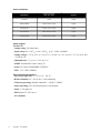
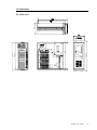
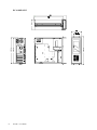
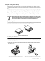
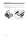
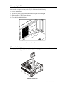
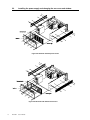
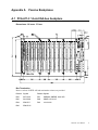
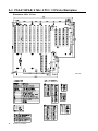
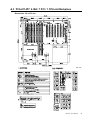
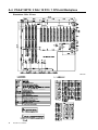
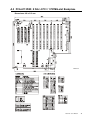
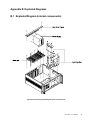
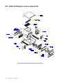
IPC-610F
Industrial PC Chassis
Copyright Notice
This document is copyrighted, March 2000, by Advantech Co., Ltd. All rights are reserved.
Advantech Co., Ltd. reserves the right to make improvements to the products described in this manual
at any time without notice.
No part of this manual may be reproduced, copied, translated or transmitted in any form or by any
means without the prior written permission of Advantech Co., Ltd. Information provided in this
manual is intended to be accurate and reliable. However, Advantech Co., Ltd. assumes no responsibility for its use, nor for any infringements of the rights of third parties which may result from its use.
Acknowledgments
IPC-610F, PCA-6113P4R, PCA-6114, PCA-6114P4, PCA-6114P4-B and PCA-6114P4R are trademarks of
Advantech Co., Ltd.
Note:
The information in this document is provided for reference only. Advantech Co.,
Ltd. does not assume any liability arising out of the application or use of the
information or products described herein. This manual is subject to change
without notice.
Part No. 2002061040
1st Edition Printed in Taiwan March 2000
Table of Contents
Chapter 1 General Information .................................................. 1
1.1 Introduction ............................................................................................................... 1
1.2 Model List .................................................................................................................. 1
1.3 Specifications ............................................................................................................ 1
1.4 Dimensions ............................................................................................................... 3
Chapter 2 System Setup .......................................................... 5
2.1 Removing the Cover ................................................................................................. 5
2.2 Adding Your Disk Drives ........................................................................................... 5
2.3 The Hold-down Clamp .............................................................................................. 6
2.4 Replacing the Filter ................................................................................................... 7
2.5 The Cooling Fan ....................................................................................................... 7
2.6 Installing the power supply and changing the rear cover and window ...................... 8
Appendix A Passive Backplanes................................................. 9
A.1 PCA-6114: 14-slot ISA-bus backplane ..................................................................... 9
A.2 PCA-6114P4-B: 9 ISA / 4 PCI / 1 CPU-slot Backplane .......................................... 10
A.3 PCA-6114P7: 6 ISA / 7 PCI / 1 CPU-slot Backplane .............................................. 11
A.4 PCA-6114P10: 3 ISA / 10 PCI / 1 CPU-slot Backplane .......................................... 12
A.5 PCA-6113P4R: 8 ISA / 4 PCI / 1 PICMG-slot Backplane ....................................... 13
Appendix B Exploded Diagrams ................................................. 15
B.1 Exploded Diagram (internal components) .............................................................. 15
B.2 Exploded Diagram (case components) ................................................................... 16
Appendix C Safety Instructions ................................................. 17
C.1 English .................................................................................................................... 17
C.2 German Wichtige Sicherheishinweise .................................................................... 18
Chapter 1 General Information
1.1 Introduction
The IPC-610F is a PC/AT-compatible computer designed for industrial applications. This rugged,
all-steel chassis meets the EIA RS-310C 19" rackmount standard. The unit includes a 14-slot PC-bus
compatible passive backplane, and a more efficient switching power supply in a single fan-cooled
chassis.
The passive backplane configuration of the IPC-610F minimizes downtime, simplifies troubleshooting,
makes upgrading easier and allows for a more efficient system package. All electronic components are
modular in design and can be easily serviced. The IPC-610F accommodates most plug-in cards,
including CPU, video, disk controller, and I/O interface cards. They can be conveniently installed and
replaced from the top of the unit.
The IPC-610F will withstand shock, vibration, dust, and a wide range of operating temperatures in
harsh industrial environments. The chassis is positively pressurized by two filtered push-pull cooling
fans to exclude dust and dirt. A lockable door protects drives and switches from tampering and foreign
particles.
1.2 Model List
Model Number
Version
Power Supply
Dimensions
(W x D x H)
IPC-610BP-30XF
Blackplane
PS-300ATX
482 x 452 x 177 mm
IPC-610MB-30XF
Motherboard
PS-300ATX
482 x 502 x 177 mm
1.3 Specifications
General
• Construction: Heavy-duty steel
• Disk drive capacity: Three half-height 5¼" drives and one 3½" drive accessible from the front
panel; and one 3½" HDD inside the chassis
• Cooling system: One 32 CFM cooling fan (flow-out) on the rear panel for the power supply, another
86 CFM fan (flow-in) with Hot-plug connector on the front panel with an air filter
• Keyboard connector: Pre-wired DIN connectors on rear panels
• Controls: Reset, power on/off and keyboard-lock switches
• Indicators: LEDs for power on/off, HDD and keyboard-lock
• Speaker: One 5 Ω, ½ watt speaker
• Weight: 18.5 kg (40.7 lb)
• Paint color: Pantone 414U
• Dimensions (W x D x H): 482 x 452 x 177 mm (19" x 17.8" x 7") for IPC-610BP-30XF,
482 x 502 x 177 mm (19" x 19.8" x 7") for IPC-610MB-30XF
IPC-610F User's Manual
1
Passive backplane
Model Name
Slots per Segment
( ISA / PCI / CPU)
Segment
PCA-6114
14 ISA
Single
PCA-6114P4-B
9 ISA / 4 PCI / 1 CPU
Single
PCA-6114P7
6 ISA / 7 PCI / 1 CPU
Single
PCA-6114P10
3 ISA / 10 PCI / 1 CPU
Single
PCA-6113P4R
8 ISA / 4 PCI / 1 CPU
Single
Power supplies
PS-300 ATX
• Output rating: 300 watts (max.)
• Input voltage: 90 ~ 130 VAC or 180 ~ 265 VAC @ 47 ~ 63 Hz, switchable
• Output voltages: +5 V @ 30 A, +12 V @ 13 A, -5 V @ 0.5 A, -12 V @ 0.8 A, +3.3 V @ 26 A, and
+5 VSB @ 2 A
• Minimum load: +5 V @ 1 A, +12 V @ 0.1 A
• MTBF: 100,000 hours at max. load @ 25°
• Safety: UL/CSA/CE/CB/NORDIC CENELEC
• EMI: FCC, VDE, CISPR 22
Environmental Specifications
• Operating temperature: 0 ~ 50° C (32 ~ 122° F)
• Relative humidity: 10 ~ 95% @ 40° C, non-condensing
• Vibration (operating): Random Vibration 5 ~ 500 Hz, 1 G RMS
• Shock (operating): 10 G acceleration peak (11 ms duration)
• Safety: C-UL approved
• EMI: Meets FCC/CE Class A
• CE compliant
2
IPC-610F User's Manual
1.4 Dimensions
48 2.00
42 6.50
43 8.50
173
IPC-610BP-30XF
IPC-610F User's Manual
3
4
IPC-610F User's Manual
48 2.00
426 .50
438 .50
173
IPC-610MB-30XF
Chapter 2 System Setup
Setting up your IPC-610F requires only a screwdriver and a small amount of time. Before you begin,
you should also gather together all of the cards you plan to install, as well as the keyboard you plan to
use.
A lockable door is located on the chassis front cover, providing access to the control panel. This offers
protection and security against damage and unauthorized access. The control panel functions include
power on/off, keyboard lock, reset switch and three LED indicators (power on, keyboard lock and
HDD) to assist in monitoring system status. On the rear panel there is a grounding point (earthing
point) located on the bottom right hand corner. This provides an earth for the whole system and is
attached via a screw.
WARNING: Disconnect all power from the chassis before you install the CPU cards. Unplug
the power cord from the wall; turning off the power switch alone is not sufficient. If
you are not sure what to do, take the job to an experienced professional.
2.1 Removing the Cover
There are screws which secure the cover to the chassis. They are along the sides, near the top. Remove them, and then slide the cover to the rear of the chassis. See Fig. 2-1 below:
Figure 2-1: Removing the cover
2.2 Adding Your Disk Drives
1. Remove the four outer screws which mount the shock-resistant drive-bay to the chassis. (See Fig. 2-2)
2. Slide the drive bay about 2 cm toward the rear, to a location where it is not obstructed by the upper
rim. Lift it free of the chassis.
3. Remove the cover to the drive bay front and insert the drives into their proper locations in the drive
bay. (See Fig. 2-3)
Figure 2-2: Inserting/removing the drive bay
Figure 2-3: Inserting the drives into the drive bay
IPC-610F User's Manual
5
2.3 The Hold-down Clamp
The IPC-610F uses a hold-down clamp to ensure the plug-in cards are securely fastened. It also offers
protection against shock and vibration. To install your cards into the passive backplane, proceed as
follows:
1. Detach the hold-down clamp by removing the two screws located at each end and lifting it off the
chassis. (See Fig. 2-4)
2. Insert the rubber buffers (provided) into the hold-down clamp. These buffers offer the plug-in cards
two levels of protection against vibration. (See Fig. 2-5)
Figure 2-4: Detaching the hold-down clamp
6
IPC-610F
User's Manual
Figure 2-5: Inserting the rubber buffers
2.4 Replacing the Filter
The filter is located next to the lockable door. Under continuous use, the filter should be removed about
once a month. To replace the filter, refer to Fig. 2-6 below and do the following:
1. Open the lockable door.
2. Take the filter out by gently pulling the tab and sliding the filter to the right.
3. Slide a new filter in until it snaps into place.
4. Close and lock the lockable door.
Figure 2-6: Replacing the filter
2.5
The Cooling Fan
The cooling fan which is inside the chassis is designed to be plugged into a connector for easy maintenance. Please refer to figure 2-7 below for illustration.
Figure 2-7: Cooling Fan
IPC-610F User's Manual
7
2.6
Installing the power supply and changing the rear cover and window
Figure 2-8: IPC-610F with backplane version
Figure 2-9: IPC-610F with motherboard version
8
IPC-610F
User's Manual
Appendix A
Passive Backplanes
A.1 PCA-6114: 14-slot ISA-bus backplane
Dimensions: 316 mm x 175 mm
Bus Termination
Reserve sockets of NETR 10P and termination resistors are provided.
Resistor Signals
Resistor Signals
RN2
SA7-SA10
RP1
SMEMW, SMEMR, IOW, IOR
RN5
SA15-SA8
RN3
SBHE, LA23-LA17
RN4
SD0-SD7
RN1
LA19-LA16
RN6
SD8-SD15
IPC-610F User's Manual
9
A.2 PCA-6114P4-B: 9 ISA / 4 PCI / 1 CPU-slot Backplane
Dimensions: 260 x 315 mm
Unit: mm
10
IPC-610F User's Manual
A.3 PCA-6114P7: 6 ISA / 7 PCI / 1 CPU-slot Backplane
Dimensions: 300 x 323 mm
Unit: mm
IPC-610F User's Manual
11
A.4 PCA-6114P10: 3 ISA / 10 PCI / 1 CPU-slot Backplane
Dimensions: 300 x 323 mm
Unit: mm
12
IPC-610F User's Manual
A.5 PCA-6113P4R: 8 ISA / 4 PCI / 1 PICMG-slot Backplane
Dimensions: 260 x 315 mm
Unit: mm
IPC-610F User's Manual
13
14
IPC-610F User's Manual
Appendix B Exploded Diagrams
B.1 Exploded Diagram (internal components)
Figure B-1: IPC-610F exploded diagram (internal components)
IPC-610F User's Manual
15
B.2 Exploded Diagram (case components)
Figure B-2: IPC-610F exploded diagram (case components)
16
IPC-610F
User's Manual
AppendixC Safety Instructions
C.1 English
1. Read these safety instructions carefully.
2. Keep this User's Manual for later reference.
3 . Disconnect this equipment from any AC outlet before cleaning. Do not use liquid or sprayed
detergent for cleaning. Use a moist sheet or cloth for cleaning.
4. For pluggable equipment, the socket-outlet should be installed near the equipment and should be
easily accessible.
5. Keep this equipment protected from humidity.
6. Lay this equipment on a reliable surface when installing it. A drop or fall could cause damage.
7. The openings on the enclosure are for air convection. Protect the equipment from overheating. DO
NOT COVER THE OPENINGS.
8. Make sure the voltage of the power source is correct when connecting the equipment to the power
outlet.
9. Place the power cord in such a way that people cannot step on it. Do not place anything over the
power cord.
10. All cautions and warnings on the equipment should be noted.
11. If the equipment is not used for a long time, disconnect it from the mains to prevent damage from
transient overvoltage.
12. Never pour any liquid into any opening. This could cause fire or electrical shock.
13. Never open the equipment. For safety reasons, the equipment should only be opened by qualified
service personnel.
14. If any of the following situations arises, get the equipment checked by service personnel:
a. The power cord or plug is damaged.
b. Liquid has penetrated into the equipment.
c. The equipment has been exposed to moisture.
d. The equipment does not work well or you cannot get it to work according to this User's Manual.
e. The equipment has been dropped and/or damaged.
f. The equipment has obvious signs of breakage.
15. DO NOT LEAVE THIS EQUIPMENT IN AN UNCONDITIONED ENVIRONMENT WHERE
THE STORAGE TEMPERATURE IS BELOW -20° C (-4° F) OR ABOVE 60° C (140° F). THIS
MAY DAMAGE THE EQUIPMENT.
The sound pressure level at the operator's position according to IEC 704-1:1982 is equal to or less
than 70 dB(A).
DISCLAIMER: This set of instructions is provided according to IEC 704-1. Advantech disclaims all
responsibility for the accuracy of any statements contained herein.
IPC-610F User's Manual
17
C2 German - Wichtige Sicherheishinweise
1. Bitte lesen sie Sich diese Hinweise sorgfältig durch.
2. Heben Sie diese Anleitung für den späteren Gebrauch auf.
3. Vor jedem Reinigen ist das Gerät vom Stromnetz zu trennen. Verwenden Sie Keine Flüssig-oder
Aerosolreiniger. Am besten dient ein angefeuchtetes Tuch zur Reinigung.
4. Die NetzanschluBsteckdose soll nahe dem Gerät angebracht und leicht zugänglich sein.
5. Das Gerät ist vor Feuchtigkeit zu schützen.
6. Bei der Aufstellung des Gerätes ist auf sicheren Stand zu achten. Ein Kippen oder Fallen könnte
Verletzungen hervorrufen.
7. Die Belüftungsöffnungen dienen zur Luftzirkulation die das Gerät vor überhitzung schützt. Sorgen
Sie dafür, daB diese Öffnungen nicht abgedeckt werden.
8. Beachten Sie beim AnschluB an das Stromnetz die AnschluBwerte.
9. Verlegen Sie die NetzanschluBleitung so, daB niemand darüber fallen kann. Es sollte auch nichts
auf der Leitung abgestellt werden.
10. Alle Hinweise und Warnungen die sich am Geräten befinden sind zu beachten.
11. Wird das Gerät über einen längeren Zeitraum nicht benutzt, sollten Sie es vom Stromnetz trennen.
Somit wird im Falle einer Überspannung eine Beschädigung vermieden.
12. Durch die Lüftungsöffnungen dürfen niemals Gegenstände oder Flüssigkeiten in das Gerät gelangen. Dies könnte einen Brand bzw. elektrischen Schlag auslösen.
13. Öffnen Sie niemals das Gerät. Das Gerät darf aus Gründen der elektrischen Sicherheit nur von
authorisiertem Servicepersonal geöffnet werden.
14. Wenn folgende Situationen auftreten ist das Gerät vom Stromnetz zu trennen und von einer qualifizierten Servicestelle zu überprüfen:
a: Netzkabel oder Netzstecker sind beschädigt.
b: Flüssigkeit ist in das Gerät eingedrungen.
c: Das Gerät war Feuchtigkeit ausgesetzt.
d: Wenn das Gerät nicht der Bedienungsanleitung entsprechend funktioni ert oder Sie mit Hilfe
dieser Anleitung keine Verbesserung erzielen.
e: Das Gerät ist gefallen und/oder das Gehäuse ist beschädigt.
f: Wenn das Gerät deutliche Anzeichen eines Defektes aufweist.
Der arbeitsplatzbezogene Schalldruckpegel nach DIN 45 635 Teil 1000 beträgt 70dB(A) oder weiger.
DISCLAIMER: This set of instructions is provided according to IEC704-1. Advantech disclaims all
responsibility for the accuracy of any statements contained herein.
18
IPC-610F User's Manual