1
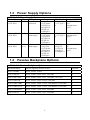
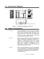
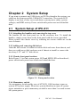
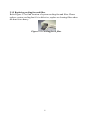
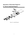
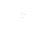
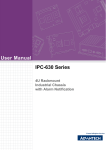
IPC-611 Series
4U Rackmount Industrial Chassis
User Manual
i
Copyright
Advantech Co., Ltd copyrights this documentation and the software included with this
product in Nov. 2005. All rights are reserved. Advantech Co., Ltd. reserves the right to
make improvements in the products described in this manual at any time without notice.
No part of this manual may be reproduced, copied, translated or transmitted in any form or
by any means without the prior written permission of Advantech Co., Ltd. Information
provided in this manual is intended to be accurate and reliable. However, Advantech Co.,
Ltd. assumes no responsibility for its use, or for any infringements of the rights of third
parties, which may result from its use.
Acknowledgments
Intel®, Pentium® and Celeron® are trademarks of Intel Corporation.
IPC-611, PCA-6113P4R-0C1, PCA-6113P7X, PCA-6114P4-C, PCA-6114P7-0D2,
PCA-6114P10-B, PCA-6114P12-0B2, PCA-6114-0B1, PCA-6114P12X-A1 are trademarks
of Advantech Co., Ltd.
All other product names or trademarks are the properties of their respective owners.
On-line Technical Support
For technical support and service, please visit our support website at:
http://www.advantech.com/support
ii
IPC-611 User Manual
A Message to the Customer
Advantech customer services
Each and every Advantech product is built to the most exacting
specifications to ensure reliable performance in the harsh and demanding
conditions typical of industrial environments. Whether your new
Advantech equipment is destined for the laboratory or the factory floor,
you can be assured that your product will provide the reliability and ease
of operation for which the name Advantech has come to be known. Your
satisfaction is our primary concern. Here is a guide to Advantech’s
customer services. To ensure you get the full benefit of our services,
please follow the instructions below carefully.
Technical support
We want you to get the maximum performance from your products. So if
you run into technical difficulties, we are here to help. For the most
frequently asked questions, you can easily find answers in your product
documentation. These answers are normally a lot more detailed than the
ones we can give over the phone.
So please consult this manual first. If you still cannot find the answer,
gather all the information or questions that apply to your problem, and
with the product close at hand, call your dealer. Our dealers are well
trained and ready to give you the support you need to get the most from
your Advantech products. In fact, most problems reported are minor and
are able to be easily solved over the phone.
In addition, free technical support is available from Advantech engineers
every business day. We are always ready to give advice on application
requirements or specific information on the installation and operation of
any of our products.
iii
Product warranty
Advantech warrants to you, the original purchaser, that each of its
products will be free from defects in materials and workmanship for two
years from the date of purchase.
This warranty does not apply to any products which have been repaired
or altered by persons other than repair personnel authorized by
Advantech, or which have been subject to misuse, abuse, accident or
improper installation. Advantech assumes no liability under the terms of
this warranty as a consequence of such events.
If an Advantech product is defective, it will be repaired or replaced at no
charge during the warranty period. For out-of-warranty repairs, you will
be billed according to the cost of replacement materials, service time and
freight. Please consult your dealer for more details.
If you think you have a defective product, follow these steps:
Step 1. Collect all the information about the problem encountered. (For
example, type of PC, CPU speed, Advantech products used,
other hardware and software used, etc.) Note anything abnormal
and list any on-screen messages you get when the problem
occurs.
Step 2. Call your dealer and describe the problem. Please have your
manual, product, and any helpful information readily available.
Step 3. If your product is diagnosed as defective, obtain an RMA (return
material authorization) number from your dealer. This allows us
to process your return more quickly.
Step 4. Carefully pack the defective product, a fully-completed Repair
and Replacement Order Card and a photocopy proof of purchase
date (such as your sales receipt) in a shippable container. A
product returned without proof of the purchase date is not
eligible for warranty service.
Step 5. Write the RMA number visibly on the outside of the package
and ship it prepaid to your dealer.
Part No. 2006061100 1st Edition
Printed Nov. 2005
iv
IPC-611 User Manual
Contents
CHAPTER 1 INFORMATION ............................................................. 2
1.1 INTRODUCTION ................................................................ 2
1.2 SPECIFICATIONS ............................................................... 2
Table 1.1: Specifications of IPC-611 ................................ 2
1.3 DIMENSION DIAGRAM ...................................................... 3
Figure 1.1: Dimension diagram of IPC-611 ..................... 4
1.4 SAFETY PRECAUTIONS ..................................................... 4
1.5 PASSIVE BACKPLANE OPTIONS ........................................ 3
Table 1.2: Passive Backplane Options.............................. 3
1.6 POWER SUPPLY OPTIONS ................................................. 3
Table 1.3: Power Supply Options ..................................... 3
CHAPTER 2 SYSTEM SETUP.......................................................... 8
2.1 SYSTEM SETUP OF IPC-611.............................................. 8
Figure 2.1: Front panel section ........................................ 8
Figure 2-2: Cooling fan & filter ....................................... 9
APPENDIX A EXPLODED DIAGRAMS ...........................................11
A.1
IPC-611 EXPLODED DIAGRAM ..................................... 11
Figure A.1: IPC-611 exploded diagram...........................11
APPENDIX B SAFETY INSTRUCTIONS ........................................ 14
v
vi
IPC-611 User Manual
CHAPTER
1
General Information
1
Chapter 1 Information
1.1 Introduction
IPC-611 is a 4U height 14-slot rackmount IPC chassis designed as a core building
block for mission-critical applications. This rugged, all-steel chassis meets the
EIA RS-310C 19” rackmount standard.
IPC-611 comes with shockproof and front accessed driver bay, three 5.25” & one
3.5”. This chassis supports a versatile 14-slot full-length passive backplane
or an ATX M/B form factor, one front accessible easy maintenance cooling fan
which provides abundant cooling. The flexible mechanical design provides PS/2
size single or redundant power supply through a power supply bracket
replacement.
A wide range of standard computing peripherals can be integrated with the
chassis to meet various application developments under mission-critical
environment 24 hours a day, 7 days a week.
1.2 Specifications
Table 1.1: Specifications of IPC-611
Front-accessible
Internal
1
3
1(85 CFM/each) and front accessible
Yes
LED display for power on and HDD activity
D-SUB 9-pin and 25-pin openings
Operating
Non-Operating
0 ~ 40 ºC (32 ~ 104 ºF)
-20 ~ 60 ºC (-4 ~ 140
ºF)
Humidity
10 ~ 85%
10 ~ 95 %
Vibration (5-500 Hz)
1 Grms
2G
Shock
10 G (With 11 msec duration,
30G
1/2 sine wave)
Altitude
10,000 ft
40,000 ft
Dimensions (W x H x D) 482 x 177 x 480 mm (19” x 7” x 18.9”)
Weight
14 kg (30.8 lb)
Safety
CE compliant, UL/cUL approved
3.5”
5.25”
Cooling
Fan
Air Filter
Miscellaneous Front LED Indicator
Rear panel
Environment
Temperature
Drive Bay
Physical
Compliance
2
IPC-611 User Manual
1.3 Power Supply Options
Table 1.2: Power Supply Options
Model Name
PS-250ATX-Z
(ATX, PFC)
Watt
250W
Input
AC 115/230
(Selected)
PS-300ATX-ZB 300W
(ATX, PFC)
AC 100 ~ 240
(Full-range)
RPS-300ATX-Z 300W
(1+1)
(ATX, PFC)
AC 100 ~ 240
(Full-range)
Output
+5V@ 27A
+3.3V@20A
+12V@13A
[email protected]
[email protected]
+5Vsb@2A
+5V@ 30A
+3.3V@28A
+12V@15A
[email protected]
[email protected]
+5Vsb@2A
+5Vsb@2A
+5V@ 25A
+3.3V@18A
+12V@16A
[email protected]
[email protected]
+5Vsb@2A
Mini-load
Safety & MTBF
+5 V @ 0.5 A UL/ CB/ TUV/
+3.3 V @ 0.3 CCC
A
100,000 hours
@25℃
+5 V @0.1 A
+3.3 V @ 0.3
A
UL/CB/CCC/TUV
100,000 hours
@25℃
[email protected]
+5V@ 3A
+3.3V@1A
+12V@2A
[email protected]
UL/CCC/CB/TUV
CE
110,000 hours
@25℃
1.4 Passive Backplane Options
Table 1.3: Passive Backplane Options
B/P Model Name
Slot per Segment (ISA/PCI/CPU)
Segment
PCA-6114-0B1
32-bit, 14-slot: 14 ISA
1
PCA-6114P4-C
32-bit, 14-slot: 8 ISA, 4 PCI, 2 PICMG
1
PCA-6114P7-0D1
32-bit, 14-slot: 4 ISA, 6 PCI, 3 PICMG, 1 PCI/ISA
1
PCA-6114P10-B
32-bit, 14-slot: 2 ISA, 10 PCI, 2 PICMG
1
PCA-6114P12-0B1
32-bit, 14-slot: 1 ISA, 11 PCI, 1 PICMG/PCI, 1 PICMG
1
PCA-6114P12X-A1
64-bit, 14-slot: 1 ISA, 11 PCI, 1 PICMG/PCI, 1 PICMG
1
PCA-6113P4R-0C1
32-bit, 13-slot: 7 ISA, 4 PCI, 2 PICMG
1
PCA-6113P7X
64-bit, 13-slot: 4 ISA, 7 PCI, 2 PICMG
1
3
1.5 Dimension Diagram
Unit : mm [ inch ]
Figure 1.1: Dimension diagram of IPC-611
1.6 Safety Precautions
Warning!
Always completely disconnect the power cord from
your chassis whenever you work with the hardware.
Do not make connections while the power is on.
Sensitive electronic components can be damaged by
sudden power surges. Only experienced electronics
personnel should open the PC chassis.
Caution!
Always ground yourself to remove any static charge
before touching the motherboard, backplane, or
add-on cards.. Modern electronic devices are very
sensitive to static electric charges. As a safety
precaution, use a grounding wrist strap at all times.
Place
all
electronic
components
on
a
static-dissipative surface or in a static-shielded bag
when they are not in the chassis.
Caution!
These servicing instructions are for use by qualified
service personnel only. To reduce the risk of electric
shock, do not perform any servicing other than that
contained in the operating instructions unless you
are qualified to do so.
4
IPC-611 User Manual
This device complies with the requirements in part
15 of the FCC rules: Operation is subject to the
following two conditions:
1.This device may not cause harmful interference,
and:
2.This device must accept any interference received,
including interference that may cause undesired
operation.
This equipment has been tested and found to
comply with the limits for a Class A digital device,
pursuant to Part 15 of the FCC Rules. These limits
are designed to provide reasonable protection
against harmful interference when the equipment is
operated in a commercial environment. This
equipment generates, uses, and can radiate radio
frequency energy and, if not installed and used in
accordance with the instruction manual, may cause
harmful interference to radio communications.
Operation of this device in a residential area is
likely to cause harmful interference in which case
the user will be required to correct the interference
at his/her own expense. The user is advised that any
equipment changes or modifications not expressly
approved by the party responsible for compliance
would void the compliance to FCC regulations and
therefore, the user's authority to operate the
equipment.
5
6
IPC-611 User Manual
CHAPTER
System Setup
7
2
Chapter 2 System Setup
If you want to connect any USB device or PS/2 keyboard to the system, you
could use the front accessible USB & PS/2 connectors. The system LED
display is on front of door cover and shows system power status, system
voltages, and HDD activity. Power switch and system reset are behind the
door.
2.1 System Setup of IPC-611
2.1.1 Attaching the handles and removing the top cover
The handles for the front panel are in the accessory box. To install the
handles, simply secure them to the front panel with the screws provided.
Please remove the chassis cover by releasing two screws which are on the
rear of chassis.
2.1.2 Adding and removing disk drives
Undo the four screws of cushion to release disk enclosure from chassis, and
then you could move disk enclosure out of chassis to install or remove the
necessary 5.25” and 3.5” disk drives.
2.1.3 Chassis front panel sections
Refer Figure 2.1 to find system power LED and HDD LED on front bezel;
power switch and system reset which are behind the door.
Figure 2.1: Front panel section
2.1.4 Momentary switch
Use momentary switch and by way of ATX (PS_ON) function to turn on
system ATX power supply. Please use system shutdown to turn off system
power automatic or press momentary switch for more than 5 seconds to turn
off system power.
8
IPC-611 User Manual
2.1.5 Replacing cooling fan and filter
Refer Figure 2.2 to find location of system cooling fan and filter. Please
replace system cooling fan if it is defective; replace or clearing filter when
the dust is too heavy.
Figure 2-2: Cooling fan & filter
9
APPENDIX
A
Exploded Diagrams
10
IPC-611 User Manual
Appendix A Exploded Diagrams
A.1 IPC-611 Exploded Diagram
Figure A.1: exploded diagram
11
APPENDIX
Safety Instructions
13
B
Appendix B Safety Instructions
1.
2.
3.
4.
5.
6.
7.
8.
9.
10.
11.
12.
13.
14.
15.
16.
17.
18.
19.
20.
21.
Read these safety instructions carefully.
Keep these instructions carefully.
Keep this installation reference guide for later reference.
Follow all instructions.
Clean only with a dry cloth.
Disconnect this equipment from any AC outlet before cleaning. Do not use
liquid or spray detergents for cleaning. Use a damp cloth.
For pluggable equipment, the power outlet must be installed near the
equipment and must be easily accessible.
Keep this equipment away from humidity or water.
Put this equipment on a reliable surface during installation. Dropping it or letting
it fall could cause damage.
The openings on the enclosure are for air convection. Protect the equipment
from overheating. DO NOT COVER THE OPENINGS.
Make sure the voltage of the power source is correct before connecting the
equipment to the power outlet.
Position the power cord so that people cannot step on it. Do not place anything
over the power cord.
Protect the power cord from being walked on or pinched particularly at plug,
convenience receptacles, and the point where they exit from the apparatus.
All cautions and warnings on the equipment should be noted.
If the equipment is not used for a long time, disconnect it from the power
source to avoid damage by transient over-voltage.
Never pour any liquid into an opening. This could cause fire or electrical shock.
Never open the equipment. For safety reasons, the equipment should be
opened only by qualified service personnel.
If any of the following situations arises, get the equipment checked by service
personnel:
a. The power cord or plug is damaged.
b. Liquid has penetrated into the equipment.
c. The equipment has been exposed to moisture or rain.
d. The equipment does not work well, or you cannot get it to work according
to the installation reference guide.
e. The equipment has been dropped and damaged.
f. The equipment has obvious signs of breakage.
DO NOT LEAVE THIS EQUIPMENT IN AN UNCONTROLLED ENVIRONMENT
WHERE THE STORAGE TEMPERATURE IS BELOW -20° C (-4° F) OR
ABOVE 60° C (140° F). THIS MAY DAMAGE THE EQUIPMENT.
Do not block any ventilation openings. Install in accordance with the
manufacturer’s instructions.
Do not install near any heat sources such as radiators, heat registers, stoves,
14
IPC-611 User Manual
or other apparatus (including amplifiers) that produce heat.
22. Do not defeat the safety purpose of the polarized or ground plug: A polarized
plug has two blades with one wider than the other. The wide blade is provided
for your safety. When the provided plug does not fit into your outlet, consult an
electrician for replacement of the obsolete outlet.
23. Only use attachments/accessories specified by the manufacturer.
24. Use only with a cart, stand, tripod, bracket, or table specified by the
manufacturer, or sold with the apparatus, When a cart is used, use caution
when moving the cart/apparatus combination to avoid injury from tip-over.
25. Unplug this apparatus during lighting storms or when unused for long periods
of time.
26. To Reduce The Risk Of Fire Or Electric Shock, Do Not Expose This Apparatus
To Rain Or Moisture.
27. Apparatus shall not be exposed to dripping or splashing and objects filled with
liquids, shall not be placed on the apparatus.
28. Only used with the battery which specified by manufacturer.
The sound pressure level at the operator's position according to IEC 704-1:1982 is
equal to or less than 70 dB (A).
DISCLAIMER: This set of instructions is given according to IEC 704-1.
Advantech disclaims all responsibility for the accuracy of any
statements contained herein.
15
16
IPC-611 User Manual