1
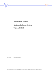
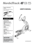
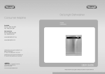
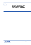
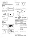
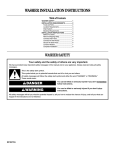
WASHER INSTALLATION INSTRUCTIONS
Table of Contents
WASHER SAFETY............................................ 1
INSTALLATION REQUIREMENTS ................. 2
Tools and Parts ............................................. 2
Location Requirements................................. 3
Drain System................................................. 3
Electrical Requirements ................................ 4
INSTALLATION INSTRUCTIONS ................... 4
Before You Start............................................ 4
Remove Shipping Strap................................ 4
Connect Drain Hose...................................... 5
Connect the Inlet Hoses ............................... 5
Secure the Drain Hose.................................. 7
Level the Washer........................................... 7
Complete Installation .................................... 8
WASHER SAFETY
Your safety and the safety of others are very important.
We have provided many important safety messages in this manual and on your appliance. Always read and obey all safety
messages.
This is the safety alert symbol.
This symbol alerts you to potential hazards that can kill or hurt you and others.
All safety messages will follow the safety alert symbol and either the word “DANGER” or “WARNING.”
These words mean:
DANGER
WARNING
You can be killed or seriously injured if you don't immediately
follow instructions.
You can be killed or seriously injured if you don't follow
instructions.
All safety messages will tell you what the potential hazard is, tell you how to reduce the chance of injury, and tell you what can
happen if the instructions are not followed.
8316566
INSTALLATION REQUIREMENTS
Tools and Parts
Gather the required tools and parts before starting installation.
The parts supplied are in the washer basket.
Tools needed for connecting the drain hose and water
inlet hoses:
■
Pliers that open to
3.95 cm (1⁹⁄₁₆")
■
Flashlight (optional)
Parts supplied:
Your installation may require additional parts. For ordering
information, please refer to the toll-free phone numbers on the
front page of the Washer User Instructions.
If You Have:
You Will Need to Buy:
Laundry tub or
standpipe taller
than 2.4 m (96")
Sump pump system (if not already
available)
2.5 cm (1")
diameter
standpipe
3.2 cm (1¹⁄₄") diameter to 2.5 cm (1")
diameter standpipe adapter kit,
Part Number 280130
Overhead sewer
Standard 76 L (20 gal.) 99 cm (39") tall
drain tub or utility sink, sump pump and
connectors (available from local
plumbing suppliers)
Floor drain
Siphon break kit, Part Number 280129;
additional drain hose,
Part Number 3357090
Water faucets
beyond reach of fill
hoses
2 longer water fill hoses:
1.8 m (6 ft) Part Number 76314,
3.0 m (10 ft) Part Number 350008
Drain hose too
short
Drain hose kit, Part Number 280131
Lint clogged drain
Drain protector, Part Number 367031
B
A
C
E
D
A. Water inlet hose (2)
B. Drain hose form
C. Large flat washer (4)
D. Small flat washer (2)
E. Inlet hose adapter
Tools needed for securing the drain hose and leveling
the washer:
■
Adjustable or open end
wrench 14 mm (⁹⁄₁₆")
■
Level
■
Wood block
■
Ruler or measuring tape
Parts supplied:
A
B
A. Beaded tie strap
B. Front leveling feet with nuts (2)
2
Alternate Parts
Location Requirements
Drain System
Selecting the proper location for your washer improves
performance and minimizes noise and possible washer “walk.”
Your washer can be installed in a basement, laundry room, closet,
or recessed area. See “Drain System.”
IMPORTANT: Do not install or store the washer where it will be
exposed to the weather.
Proper installation is your responsibility.
You will need:
■
A water heater set to deliver 49°C (120°F) water to the washer.
■
An earthed electrical outlet located within 1.2 m (4 ft) of where
the power cord is attached to the back of the washer. See
“Electrical Requirements.”
■
Hot and cold water faucets located within 90 cm (3 ft) of the
hot and cold water fill valves, and water pressure of 34.5690 kPa (5-100 psi). Washers with triple dispensers require
138-690 kPa (20-100 psi) for best performance.
■
A level floor with a maximum slope of 2.5 cm (1") under entire
washer. Installing the washer on carpeting is not
recommended.
■
A sturdy floor to support the washer weight (washer, water
and load) of 143 kg (315 lbs).
Do not store or operate your washer in temperatures at or below
0°C (32°F). Some water can remain in the washer and can cause
damage in low temperatures. See “Washer Care” in the Washer
User Instructions for winterizing information.
The washer can be installed using the standpipe drain system
(floor or wall), the laundry tub drain system, or the floor drain
system. Select the drain hose installation method you need. See
“Tools and Parts.”
Standpipe drain system - wall or floor (views A & B)
The standpipe drain requires a minimum diameter standpipe of
5 cm (2"). The minimum carry-away capacity can be no less than
64 L (17 gal.) per minute. A 3.2 cm (1¹⁄₄") diameter to 2.5 cm (1")
diameter standpipe adapter kit is available. See “Tools and Parts.”
The top of the standpipe must be at least 99 cm (39") high and no
higher than 244 cm (96") from the bottom of the washer.
99 cm
(39")
A
B
Laundry tub drain system (view C)
Recessed area or closet installation
The dimensions shown are for the recommended spacing allowed
(A and B), except the closet door ventilation openings. The
dimensions shown for the closet door ventilation openings (C) are
the minimum required.
35.6 cm
(14" max.)
7.6 cm
(3")
2
310 cm2
(48 in. )
The laundry tub needs a minimum 76 L (20 gal.) capacity. The top
of the laundry tub must be at least 99 cm (39") above the floor and
no higher than 244 cm (96") from the bottom of the washer.
Floor drain system (view D)
The floor drain system requires a siphon break that may be
purchased separately. See “Tools and Parts.”
The siphon break must be a minimum of 71 cm (28") from the
bottom of the washer. Additional hoses might be needed.
48.3 cm
(19")
2
155 cm2
(24 in. )
0 cm
(0")
68.6 cm
(27")
A
0 cm
(0")
64.8 cm
2.5 cm (25¹⁄₂")
(1")
99 cm
(39")
7.6 cm
(3")
71 cm
(28")
10.2 cm
(4")
B
C
A. Front view
B. Side view
C. Closet door with vents
■
Additional spacing should be considered for ease of
installation and servicing.
■
Additional clearances may be required for wall, door and floor
moldings.
■
Additional spacing of 2.5 cm (1") on all sides of the washer is
recommended to reduce noise transfer.
■
If a closet door is installed, the minimum air openings in the
top and bottom of the door are required (C). Louvered doors
with air openings in the top and bottom are acceptable.
■
Companion appliance spacing should also be considered.
C
D
3
Electrical Requirements
WARNING
■
Do not earth to a gas pipe.
■
Check with a qualified electrician if you are not sure the
washer is properly earthed.
■
Do not have a fuse in the neutral or earth circuit.
EARTHING INSTRUCTIONS
Electrical Shock Hazard
Electrically earth this appliance.
Do not use an extension cord or an electrical portable
outlet device.
Failure to follow these instructions can result in death,
fire, or electrical shock.
■
A 230 volt, 50 Hz., AC only, 10-amp, fused electrical supply is
required. A time-delay fuse or circuit breaker is recommended.
It is recommended that a separate circuit serving only this
appliance be provided.
■
This washer is equipped with a power supply cord having an
earthing plug.
■
To minimize possible shock hazard, the cord must be plugged
into a mating, earthing-type outlet, earthed in accordance with
local codes and ordinances. If a mating outlet is not available,
it is the personal responsibility and obligation of the customer
to have the properly earthed outlet installed by a qualified
electrician.
■
If codes permit and a separate earth wire is used, it is
recommended that a qualified electrician determine that the
earth path is adequate.
■
The installer is to confirm, through the local power supply
authority, if necessary, that the machine is connected to a
power supply with a maximum impedance of 0.068 + j0.043
ohms for phases (RA + jXA) and 0.0455 + j0.02844 ohms for
neutral (RN + jXN).
For an earthed, cord-connected washer:
This washer must be earthed. In the event of a malfunction
or breakdown, earthing will reduce the risk of electrical
shock by providing a path of least resistance for electric
current. This washer is equipped with a cord having an
equipment-earthing conductor and an earthing plug. The
plug must be plugged into an appropriate outlet that is
properly installed and earthed in accordance with all local
codes and ordinances.
WARNING: Improper connection of the equipmentearthing conductor can result in a risk of electric shock.
Check with a qualified electrician or serviceman if you are in
doubt as to whether the appliance is properly earthed.
Do not modify the plug provided with the appliance – if it will
not fit the outlet, have a proper outlet installed by a qualified
electrician.
For a permanently connected washer:
This washer must be connected to an earthed metal,
permanent wiring system, or an equipment earthing
conductor must be run with the circuit conductors and
connected to the equipment-earthing terminal or lead on the
appliance.
INSTALLATION INSTRUCTIONS
Before You Start
3. Locate the yellow shipping strap on the rear of the machine
near the bottom.
WARNING
Excessive Weight Hazard
Use two or more people to move and install washer.
Failure to do so can result in back or other injury.
NOTE: To avoid floor damage, set the washer onto cardboard
before moving across floor.
Remove Shipping Strap
Removing the shipping strap is necessary for proper operation. If
the shipping strap is not removed, the washer will make excessive
noise.
1. Move the washer to within approximately 90 cm (3 ft) of its
final location.
2. The washer must be in the upright position and not tilted
before removing the shipping strap.
4
A
A. Yellow shipping strap
4. Pull yellow shipping strap firmly, until both ends are
completely removed from washer.
Laundry tub drain or standpipe drain
Connecting the drain hose form to the corrugated
drain hose
C
5. Check that the two (2) cotter pins were removed with the
shipping strap.
A
B
A. Place end of drain hose form around hose at drain hose relief.
Squeeze the latch of the drain hose form until it snaps into place.
B. Place the other end of the drain hose form around one of the
remaining drain hose reliefs. Squeeze the latch of the drain hose
form until it snaps into place.
C. Drain hose relief
To keep drain water from going back into the washer:
■
Do not force excess drain hose into standpipe. Hose should
be secure but loose enough to provide a gap for air.
■
Do not lay excess hose on the bottom of the laundry tub.
Floor drain
Connect Drain Hose
Proper connection of the drain hose protects your floors from
damage due to water leakage. Read and follow these instructions.
The drain hose is connected to your washer and is stored inside
the washer cabinet.
Remove drain hose from washer cabinet
Gently pull the corrugated drain hose out of the washer from the
top of the hose. Continue to pull the hose until the end emerges.
Do not force excess drain hose back into the rear of the washer.
Do not install the drain hose form on to the corrugated drain hose.
You may need additional parts. See Floor drain under “Tools and
Parts.”
Connect the Inlet Hoses
1. Insert one new large flat washer into one end of each inlet
hose. Firmly seat the washers in the couplings.
2. Screw on the hose adapter by hand until it is seated on the
washer. Using pliers, tighten the hose adapter with an
additional two-thirds turn.
A
B
A. Inlet hose coupling
B. Large flat washer
C
D
C. Hose adapter
D. Small flat washer
NOTE: Do not overtighten.
3. Insert one new small flat washer into the end of the hose
adapter. Firmly seat the washers in the couplings.
5
Connect the inlet hoses with the adapters, to the water faucets
Connect the inlet hoses to the washer
Make sure the washer basket is empty.
1. Attach the end of the hose with the adapter, labeled hot, to the
hot water faucet. Screw on coupling by hand until it is seated
on the washer.
2. Attach the end of the hose with the adapter, labeled cold, to
the cold water faucet. Screw on coupling by hand until it is
seated on the washer.
3. Using pliers, tighten the couplings with an additional
two-thirds turn.
A
B
A. Cold water inlet valve
B. Hot water inlet valve
1. Attach the hot water hose to the bottom inlet valve.
2. Attaching the hot water coupling first makes it easier to
tighten connection with pliers.
3. Screw on coupling by hand until it is seated on the washer.
Tighten the couplings with an additional two-thirds turn.
NOTE: Do not overtighten or use tape or sealants on the
valve. Damage to the valves can result.
Clear the water lines
1. Run water through both faucets and inlet hoses, into a laundry
tub, drainpipe or bucket, to get rid of particles in the water
lines that might clog the inlet valve screens.
2. Check the temperature of the water to make sure that the hot
water hose is connected to the hot water faucet and that the
cold water hose is connected to the cold water faucet.
3. Insert new large flat washers (supplied) into each end of the
inlet hoses. Firmly seat the washers in the couplings.
4. Using pliers, tighten the couplings with an additional
two-thirds turn.
NOTE: Do not overtighten or use tape or sealants on the
valve. Damage to the valves can result.
5. Attach the cold water hose to the top inlet valve.
6. Screw on coupling by hand until it is seated on the washer.
7. Using pliers, tighten the couplings with an additional
two-thirds turn.
NOTE: Do not overtighten or use tape or sealants on the
valve. Damage to the valves can result.
Check for leaks
■
A
A. Coupling
6
B
B. Washer
Turn on the water faucets and check for leaks. A small amount
of water might enter the washer. You will drain this later.
NOTE: Replace inlet hoses after 5 years of use to reduce the
risk of hose failure. Record hose installation or replacement
dates for future reference.
■
If you connect only one water hose, you must cap off the
remaining water inlet port.
■
Periodically inspect and replace hoses if bulges, kinks,
cuts, wear, or leaks are found.
2. Screw the locknut onto each foot to within 2.5 cm (1") of the
foot base.
Secure the Drain Hose
1. Remove the shipping strap from the power cord. Drape the
power cord over the console.
2. Remove any cardboard used to move washer.
2.5 cm
(1")
3. Screw the feet into the threaded holes at the front corner of
the washer until the nuts touch the washer. Twist the feet to
install.
NOTE: Do not tighten the nuts until the washer is level.
Beaded tie strap
3. Wrap the drain hose to the laundry tub leg or drain standpipe
with the beaded tie strap. Push fastener into the nearest hole
in the beaded tie strap. See view A or B.
4. Tilt the washer back and remove the wood block. Gently lower
the washer to the floor.
Steps in Final Location
A
B
C
If the washer faucets and the drain standpipe are recessed,
put the formed end of the drain hose into the standpipe.
Tightly wrap the tie strap around the water inlet hoses and the
drain hose. See view C.
1. Slide the washer to its final location.
2. Tilt the washer forward until the rear of the washer is at least
10.2 cm (4") off the floor. You may hear the self-adjusting rear
feet click into place. Lower the washer to the floor.
Level the Washer
Properly leveling your washer averts excessive noise and
vibration.
Install the Front Leveling Feet
1. Prop up the front of the washer about 10.2 cm (4") with a
wood block or similar object. The block needs to support the
weight of the washer.
10.2 cm
(4")
A
A. Self-adjusting feet
3. Check the levelness of the washer by placing a level on the
top edges of the washer, first side to side, then front to back.
10.2 cm
(4")
A
A. Threaded holes for feet
7
4. If the washer is not level, move the washer out slightly, tip
back, prop up the front of the washer with the wood block and
adjust the feet up or down as necessary by twisting the feet.
Turn the feet clockwise to raise the washer or
counterclockwise to lower the washer. Repeat steps
1 through 4 until washer is level.
5. After the washer is in its final location and level, use a 14 mm
or ⁹⁄₁₆" open-end wrench to turn the nuts counterclockwise on
the feet tightly against the washer cabinet.
IMPORTANT: If the nuts are not tight against the washer
cabinet, the washer may vibrate.
Complete Installation
1. Check the electrical requirements. Be sure that you have the
correct electrical supply and the recommended earthing
method. See “Electrical Requirements.”
2. Check that all parts are now installed. If there is an extra part,
go back through the steps to see which step was skipped.
3. Check that you have all of your tools.
4. Check that the yellow shipping strap was completely removed
from the lower back of the washer.
5. Dispose of or recycle all packaging materials.
6. Check that the water faucets are on.
7. Check for leaks around faucets and inlet hoses.
WARNING
Electrical Shock Hazard
Electrically earth this appliance.
Do not use an extension cord or an electrical portable
outlet device.
Failure to follow these instructions can result in death,
fire, or electrical shock.
8. Plug into an earthed outlet.
9. Remove the protective film on the console and any tape
remaining on the washer.
10. Read “Washer Use” in the Washer User Instructions.
11. To test and to clean your washer, measure ¹₂ of the normal
recommended amount of powdered or liquid detergent and
pour it into the washer basket or detergent dispenser (on
some models). Close the lid. Select any cycle, and then pull
the cycle control knob out to start the washer. Allow it to
complete one whole cycle.
8316566
© 2005 Whirlpool Corporation.
Benton Harbor, Michigan 49022
8/05
Printed in U.S.A.