1
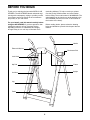
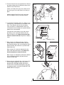
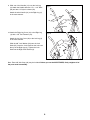
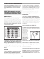
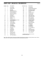
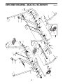
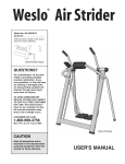
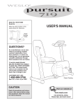
Model No. WLAW55078
Serial No.
Write the serial number in the space
above for future reference.
Serial Number Decal
QUESTIONS?
As a manufacturer, we are committed to providing complete
customer satisfaction. If you
have questions, or find that there
are missing or damaged parts,
we will guarantee complete satisfaction through direct assistance from our factory.
TO AVOID UNNECESSARY
DELAYS, PLEASE CALL DIRECT
TO OUR TOLL-FREE CUSTOMER
HOT LINE. The trained technicians on our customer hot line
will provide immediate assistance, free of charge to you.
CUSTOMER HOT LINE:
1-800-999-3756
Mon.ÐFri., 6 a.m.Ð6 p.m. MST
Patent Pending
CAUTION
Read all precautions and instructions in this manual before
using this equipment. Save this
manual for future reference.
USER'S MANUAL
TABLE OF CONTENTS
IMPORTANT PRECAUTIONS . . . . . . . . . . . . . . . . . . . . . . . . . . . . . . . . . . . . . . . . . . . . . . . . . . . . . . . . . . . . .3
BEFORE YOU BEGIN . . . . . . . . . . . . . . . . . . . . . . . . . . . . . . . . . . . . . . . . . . . . . . . . . . . . . . . . . . . . . . . . . . .4
ASSEMBLY . . . . . . . . . . . . . . . . . . . . . . . . . . . . . . . . . . . . . . . . . . . . . . . . . . . . . . . . . . . . . . . . . . . . . . . . . . .5
HOW TO USE THE AIR STRIDER . . . . . . . . . . . . . . . . . . . . . . . . . . . . . . . . . . . . . . . . . . . . . . . . . . . . . . . . . .9
STORAGE AND TROUBLE-SHOOTING . . . . . . . . . . . . . . . . . . . . . . . . . . . . . . . . . . . . . . . . . . . . . . . . . . . . .11
CONDITIONING GUIDELINES . . . . . . . . . . . . . . . . . . . . . . . . . . . . . . . . . . . . . . . . . . . . . . . . . . . . . . . . . . . .12
PART LIST . . . . . . . . . . . . . . . . . . . . . . . . . . . . . . . . . . . . . . . . . . . . . . . . . . . . . . . . . . . . . . . . . . . . . . . . . . .14
EXPLODED DRAWING . . . . . . . . . . . . . . . . . . . . . . . . . . . . . . . . . . . . . . . . . . . . . . . . . . . . . . . . . . . . . . . . .15
ORDERING REPLACEMENT PARTS . . . . . . . . . . . . . . . . . . . . . . . . . . . . . . . . . . . . . . . . . . . . . . . .Back Cover
LIMITED WARRANTY . . . . . . . . . . . . . . . . . . . . . . . . . . . . . . . . . . . . . . . . . . . . . . . . . . . . . . . . . . .Back Cover
2
IMPORTANT PRECAUTIONS
WARNING: To reduce the risk of serious injury, read the following important precautions before
using the AIR STRIDER.
1. It is the responsibility of the owner to ensure
that all users of the AIR STRIDER are
adequately informed of all warnings and
precautions.
9. Keep hands and feet away from moving parts.
2. Read all instructions in this manual before
using the AIR STRIDER.
11. Always wear athletic shoes for foot protection when exercising on the AIR STRIDER.
3. Use the AIR STRIDER only as described in
this manual.
12. When you are getting onto and off the AIR
STRIDER, tighten the resistance dials, hold
the handles firmly, and be sure that your
body weight is centered directly over the
pedals.
10. Do not wear loose clothing that could
become caught on the AIR STRIDER.
4. Use the AIR STRIDER only on a level surface.
Cover the floor beneath the AIR STRIDER to
protect the floor or carpet.
13. If you feel faint, dizzy, or short of breath while
exercising, stop immediately and begin cooling down.
5. Be sure that there are no persons or obstacles in front of or behind the AIR STRIDER.
14. When folding the AIR STRIDER for storage,
hold the resistance dials to prevent your
hands from being pinched.
6. Inspect and tighten all parts regularly.
Replace any worn parts immediately.
7. Keep children and pets away from the AIR
STRIDER at all times.
15. The AIR STRIDER is intended for home use
only. Do not use the AIR STRIDER in any
commercial, rental, or institutional setting.
8. The AIR STRIDER should not be used by persons weighing more than 250 pounds.
WARNING: Before beginning this or any exercise program, consult your physician. This is especially
important for persons over the age of 35 or persons with pre-existing health problems. Read all
instructions before using. ICON assumes no responsibility for personal injury or property damage
sustained by or through the use of this product.
3
BEFORE YOU BEGIN
Thank you for selecting the innovative WESLO¨ AIR
STRIDER. The AIR STRIDER blends advanced engineering with contemporary styling to provide you with
a no-impact, total body workout in the convenience
and privacy of your own home.
(excluding holidays). To help us assist you, please
note the product model number and serial number
before calling. The model number is WLAW55078. The
serial number can be found on a decal attached to the
AIR STRIDER (see the front cover of this manual for
the location of the decal).
For your benefit, read this manual carefully before
using the AIR STRIDER. If you have questions after
reading the manual, call our Customer Service
Department toll-free at 1-800-999-3756, Monday
through Friday, 6 a.m. until 6 p.m. Mountain Time
Before reading further, please review the drawing
below and familiarize yourself with the parts that are
labeled.
Handle
Electronic Monitor
Resistance Dial
Lock Knob
Hip Pad
Frame
Upright
Link Arm
Leg
Pedal
4
ASSEMBLY
Assembly requires two people. Place all parts of the AIR STRIDER in a cleared area and remove the packing
materials. Do not dispose of the packing materials until assembly is completed. Read through all steps before
beginning assembly. As you assemble the AIR STRIDER, make sure that all parts are oriented as shown in the
drawings. Tighten all parts as you assemble them, unless instructed to do otherwise. Refer to the drawings
below to identify the small hardware used in assembly. Note: If a part is not found in the parts bag, check to
see if it has been pre-attached.
Assembly requires two adjustable wrenches
screwdriver
(not included).
3/8Ó Lock Washer (58)Ñ1
Plastic Spacer (41)Ñ2
#8 x 3/4" Screw (23)Ñ1
, a hammer
1/4" Nylon Locknut (59)Ñ4
, and a phillips
3/8" Nylon Locknut (43)Ñ2
Bronze Bushing (16)Ñ4
3/8" Flat Washer (39)Ñ8
1/4Ó x 1 1/2Ó Bolt (60)Ñ4
3/8" Axle Cap (40)Ñ4
1/8Ó Tree Fastener (32)Ñ2
3/8" x 4" Screw (44)Ñ4
3/8Ó x 5 1/2Ó Bolt (42)Ñ2
1. Read all instructions at the top of this page
before beginning assembly.
Fig. 1
Stop
Rods
Refer to the drawing at the right and identify the
Left and Right Uprights (1, 2). Note the location of
the stop rods.
2
1
Turn the Crossbar (10) so the Rocker Arm (9) is at
the top. Attach the Crossbar to the Left Upright (1)
with two 3/8Ó x 4Ó Screws (44) and two 3/8Ó Flat
Washers (39). Do not tighten the Screws yet.
Attach the Crossbar to the Right Upright (2) in the
same manner.
39
44
5
10
9
2. Refer to figure 2b. Slide a Finger Guard (54) onto
the pins on the Left Pivot Bracket (7). Note: The
Finger Guards may already be attached.
7 Pin
Fig. 2a
Find the Left Link Arm (11), identified with a decal.
Make sure that there is a Bronze Bushing (16) in
each end of the Link Arm. Slide one end of the Link
Arm onto the indicated pin on the Left Pivot
Bracket (7). Slide a 3/8Ó Flat Washer (39) onto the
pin and tap a 3/8Ó Axle Cap (40) onto the pin. Slide
the other end of the Link Arm onto the pin on the
Rocker Arm (9). (Note: It may be necessary to pivot
the Rocker Arm and the Left Leg [3] slightly.) Slide
a 3/8Ó Flat Washer (39) onto the pin and tap a 3/8Ó
Axle Cap (40) onto the pin.
16
39
11
40
3
9
Fig. 2b
Attach the other Finger Guard and Link Arm (not
shown) in the same manner.
54
39
Pin
3. Attach the Right Frame Section (6) to the Right
Upright (2) with a 3/8Ó x 5 1/2Ó Bolt (42), a Plastic
Spacer (41), and a 3/8Ó Nylon Locknut (43). Do
not tighten the Nylon Locknut yet.
7
Pins
40
16
Fig. 3
42
43
41
2
4. Slide the Hip Pad (28) onto the Left Frame
Section (5).
Fig. 4
Slide the Left and Right Frame Sections (5, 6)
together. Make sure that the indicated hole is
accessible. If necessary, slide the Hip Pad (28) to
the side. Attach the Frame Sections with a #8 x
3/4Ó Screw (23). Do not tighten the Screw yet.
6
Hole
23
28
43
5
41
Attach the Left Frame Section (5) to the Left
Upright (1) with a 3/8Ó x 5 1/2Ó Bolt (42), a Plastic
Spacer (41), and a 3/8Ó Nylon Locknut (43).
42
1
Tighten all parts used in steps 1, 3, and 4.
Slide the Hip Pad (28) so it is centered on the
Frame Sections (5, 6).
6
6
5. Turn the Pedal Covers (27) upside-down. Remove
the paper backing from the adhesive strips on the
bottoms of the Pedal Cover.
Fig. 5
27
27
Center one Pedal Cover (27) on the lower end of
the Left Leg (3). Press the Pedal Cover firmly in
place.
Attach the other Pedal Cover (27) to the lower
end of the Right Leg (4) in the same manner.
4
3
6. If your Electronic Monitor (50) has a battery cover
(see figure 6), install batteries as described in this
step. If your Monitor does not have a battery
cover, see step 7 to install batteries. Note: Two
ÒAAÓ batteries (not included) are required. Alkaline
batteries are recommended.
Fig. 6
50
Press the tab on the battery cover and remove
the battery cover. Insert two batteries into the
Electronic Monitor (50). Make sure that the batteries are turned as shown. Replace the battery
cover.
Battery Cover
7. Refer to figure 7a. Remove the two Console
Screws (48) from the Monitor Bracket (45) and
the Electronic Monitor (50). Lift the Monitor off the
Monitor Bracket. Be careful not to pull the Reed
Switch Wire (47).
Fig. 7b
Fig. 7a
50
Refer to figure 7b. Insert two batteries into the
back of the Electronic Monitor (50). Make sure
that the batteries are turned as shown.
48
47
Refer to figure 7a. Reattach the Electronic Monitor
(50) to the Monitor Bracket (45) with the two
Console Screws (48).
50
45
8. Remove the two indicated 3/8Ó x 3/4Ó Screws (23)
from the Right Upright (2). Attach the Monitor
Bracket (45) to the Right Upright with the two
Screws. Note: If the Electronic Monitor (50) does
not operate properly, see HOW TO ADJUST THE
REED SWITCH on page 11.
Fig. 8
50
23
45
2
7
9. Slide one of the Handles (13) onto the Left Leg
(3). Attach the Handle with two 1/4Ó x 1 1/2Ó Bolts
(60) and two 1/4Ó Nylon Locknuts (59).
Fig. 9
13
Attach the other Handle (13) to the Right Leg (4)
in the same manner.
13
60
59
4
Holes
3
10. Attach the Right Leg Cover (31) to the Right Leg
(4) with a 1/8Ó Tree Fastener (32).
Fig. 10
8
Attach the Left Leg Cover (30) to the Left Leg (3)
in the same manner.
31
Slide the 3/8Ó Lock Washer (58) onto the Lock
Knob (25). Insert the Lock Knob into the hole near
the top of the Right Leg (4). Tighten the Lock
Knob into the Right Pivot Bracket (8).
32
30
58
4
25
3
Note: Extra 3/8Ó Axle Caps (40) may be included. Before you use the AIR STRIDER, firmly retighten all of
the parts used in assembly.
8
HOW TO USE THE AIR STRIDER
ELECTRONIC MONITOR MODES
CAUTION: When you are getting onto and off
the AIR STRIDER, always tighten the resistance dials, hold the handles firmly, and be
sure that your body weight is centered directly over the pedals.
The simple-to-operate electronic monitor offers
five different modes to provide instant exercise
feedback. The five modes are described below:
SpeedÑDisplays the number of repetitions you are
performing per minute.
EXERCISING ON THE AIR STRIDER
TimeÑDisplays the length of time you have exercised. Note: If you stop exercising for ten seconds or
longer, the time mode will pause until you resume.
Make sure that the lock knob is tightened into the
right leg and pivot bracket (see assembly step 10 on
page 8). Tighten the resistance dials, hold the handles, and step onto the pedals. The proper form for
exercising on the AIR STRIDER is similar to the
motion of walkingÑmove one leg forward as you
move the other leg back.
DistanceÑDisplays the total number of repetitions
you have completed, up to Ò999.Ó The display will then
reset to Ò0Ó and continue counting.
CaloriesÑDisplays the approximate number of
Calories you have burned. Note: If the resistance is
near the highest or lowest setting, the actual number
of Calories you have burned will be slightly higher or
lower than the number displayed.
For a full body workout, hold the handles as you walk,
and move your arms and legs in motion with the handles and pedals. To vary the effect of the exercise on
your muscles, change your stance on the AIR
STRIDER. For example, stand erect or lean against
the hip pad, change the position of your hands on the
handles, or bend your legs slightly instead of keeping
them straight.
ScanÑDisplays the speed, time, distance, and calories modes, for approximately 5 seconds each,
in a repeating cycle.
DIAGRAM OF THE ELECTRONIC MONITOR
For a lower body workout, rest your hands on the
frame for balance as you move the pedals.
RESISTANCE ADJUSTMENT
1
To vary the intensity of your workout, the resistance of
the AIR STRIDER can be changed. To increase the
resistance, turn the resistance dials clockwise. To
decrease the resistance, turn the resistance dials
counterclockwise.
2
Resistance
Dials
3
4
1. LCD displayÑDisplays all modes.
2. Mode indicatorsÑShow which mode is selected.
3. Mode buttonÑSelects all modes.
4. On/Reset buttonÑTurns the power on and resets
all modes.
9
OPERATING THE ELECTRONIC MONITOR
Speed, time, distance, or calories modeÑ
These modes can be individually selected by
repeatedly pressing the mode button. The mode
indicators will show which mode has been selected. (Make sure that the scan mode is not selected.) The modes will be selected in the following
order: speed, time, distance, calories, scan.
1. To turn on the power, press the on/reset button or
simply begin exercising on the AIR STRIDER. The
entire display will appear for two seconds. The
electronic monitor will then be ready for operation.
2. Select one of the five modes:
3. The monitor has an auto-off feature to turn off
the power. If the pedals are not moved and the
monitor buttons are not pressed for four minutes,
the power will turn off automatically in order to
conserve the batteries.
Scan modeÑWhen the power is turned on, the
scan mode will be selected automatically. The
scan mode can also be selected by repeatedly
pressing the mode button. One mode indicator will
show that the scan mode has been selected, and
a second mode indicator will show which mode is
currently displayed.
To reset the LCD display, press the on/reset button.
10
STORAGE AND TROUBLE-SHOOTING
Inspect and tighten all parts of the AIR STRIDER regularly. Replace any worn parts immediately. The AIR
STRIDER can be cleaned with a soft, damp cloth.
Keep liquids away from the electronic monitor. Keep
the monitor out of direct sunlight or the display may
be damaged. Remove the batteries when storing the
AIR STRIDER.
REPLACING THE BATTERIES
If the display of the electronic monitor becomes dim,
or if the monitor does not function properly, the batteries should be replaced. To replace the batteries, refer
to assembly step 6 or 7 on page 7.
HOW TO ADJUST THE REED SWITCH
HOW TO FOLD THE AIR STRIDER FOR STORAGE
If the speed and distance modes do not display correct information, the reed switch should be adjusted.
The reed switch is
located below the
electronic monitor
(see the drawing at
Magnet
the right). Loosen the
screw in the reed
switch, move the reed
switch to the side
slightly, and retighten
Reed
the screw. Make sure
Switch
that the reed switch
does not hit the
indicated magnet when the AIR STRIDER is in
use. Repeat until the speed and distance modes
display correct information.
When the AIR STRIDER is not in use, it can be folded
for compact storage. To fold the AIR STRIDER, first
remove the lock knob and lock washer from the right
leg. Next, hold the resistance dials and fold the frame
and the uprights together. Place the AIR STRIDER in
a location where it cannot fall.
Lock
Washer
Lock
Knob
Resistance
Knob
Upright
Frame
11
CONDITIONING GUIDELINES
The following general guidelines will help you to plan
your exercise program. Remember that proper nutrition and adequate rest are essential for successful
results.
gy. Only after the first few minutes of exercise does
your body begin to use stored fat calories for energy. If
your goal is to burn fat, adjust your pace or the resistance until your heart rate is near the lowest number
in your training zone as you exercise.
WARNING: Before beginning this or any exercise
program, consult your physician. This is especially important for individuals over the age of 35
or individuals with pre-existing health problems.
For maximum fat burning, adjust your pace or the
resistance until your heart rate is near the middle
number in your training zone as you exercise.
Aerobic Exercise
EXERCISE INTENSITY
If your goal is to strengthen your cardiovascular system, your exercise must be Òaerobic.Ó Aerobic exercise
is activity that requires large amounts of oxygen for
prolonged periods of time. This increases the demand
on the heart to pump blood to the muscles, and on the
lungs to oxygenate the blood. For aerobic exercise,
adjust your pace or the resistance until your heart rate
is near the highest number in your training zone as
you exercise.
Whether your goal is to burn fat or strengthen your
cardiovascular system, the key to achieving the
desired results is to exercise with the proper intensity.
The proper intensity level can be found by using your
heart rate as a guide. The chart below shows recommended heart rates for fat burning, maximum fat burning, and cardiovascular (aerobic) exercise. (This chart
is also found on the console.)
HOW TO MEASURE YOUR HEART RATE
To measure your heart rate, first exercise for at least
four minutes. Then, stop exercising and place two fingers on your wrist as shown. Take a six-second heartbeat count, and
multiply the result
by 10 to find your
heart rate. For
example, if your
six-second heartbeat count is 14,
your heart rate is
140 beats per
minute. (A six-second count is used
because your
heart rate will drop rapidly when you stop exercising.)
To find the proper heart rate for you, first find your age
on either side of the chart (ages are rounded off to the
nearest ten years). Next, find the three numbers to the
side of your age. The three numbers are your Òtraining
zone.Ó The lowest number is the recommended heart
rate for fat burning; the middle number is the recommended heart rate for maximum fat burning; the highest number is the recommended heart rate for aerobic
exercise.
Adjust the intensity of your exercise until your heart
rate is at the desired level. You can adjust the intensity
of your exercise by changing your pace or by adjusting the resistance.
WORKOUT GUIDELINES
Each workout should include the following three parts:
Fat Burning
A warm-up, consisting of 5 to 10 minutes of stretching
and light exercise. A proper warm-up increases the
body temperature, heart rate, and circulation in preparation for strenuous exercise.
To burn fat effectively, you must exercise at a relatively low intensity level for a sustained period of time.
During the first few minutes of exercise, your body
uses easily accessible carbohydrate calories for ener-
12
Training zone exercise, consisting of 20 to 30 minutes of exercising with your heart rate in your training
zone.
EXERCISE FREQUENCY
To maintain or improve your condition, plan three
workouts each week, with at least one day of rest
between workouts. After a few months of regular exercise, you may complete up to five workouts each
week, if desired.
A cool-down, with 5 to 10 minutes of stretching.
Thorough stretching helps to offset problems caused
when you stop exercising suddenly. Stretching for
increased flexibility is also most effective after exercising. A proper cool-down should leave you relaxed and
comfortably tired.
Remember, the key to success is make exercise a
regular and enjoyable part of your everyday life.
SUGGESTED STRETCHES
The correct form for several basic stretches is shown in the
drawings below. Move slowly as you stretchÑnever bounce.
1
1. Toe Touch Stretch
Stand with your knees bent slightly and slowly bend forward
from your hips. Allow your back and shoulders to relax as you
reach down toward your toes as far as possible. Hold for 15
counts, then relax. Repeat 3 times. Stretches: Hamstrings,
back of knees and back.
2
2. Hamstring Stretch
Sit with one leg extended. Bring the sole of the opposite foot
toward you and rest it against the inner thigh of your extended
leg. Reach toward your toes as far as possible. Hold for 15
counts, then relax. Repeat 3 times for each leg. Stretches:
Hamstrings, lower back and groin.
3
3. Calf/Achilles Stretch
With one leg in front of the other, reach forward and place
your hands against a wall. Keep your back leg straight and
your back foot flat on the floor. Bend your front leg, lean forward and move your hips toward the wall. Hold for 15 counts,
then relax. Repeat 3 times for each leg. To cause further
stretching of the achilles tendons, bend your back leg as well.
Stretches: Calves, achilles tendons and ankles.
4
4. Quadriceps Stretch
With one hand against a wall for balance, reach back and
grasp one foot with your other hand. Bring your heel as close
to your buttocks as possible. Hold for 15 counts, then relax.
Repeat 3 times for each leg. Stretches: Quadriceps and hip
muscles.
5. Inner Thigh Stretch
Sit with the soles of your feet together and your knees outward. Pull your feet toward your groin area as far as possible.
Hold for 15 counts, then relax. Repeat 3 times. Stretches:
Quadriceps and hip muscles.
13
5
PART LISTÑModel No. WLAW55078
Key No. Qty.
1
2
3
4
5
6
7
8
9
10
11
12
13
14
15
16
17
18
19
20
21
22
23
24
25
26
27
28
29
30
31
32
1
1
1
1
1
1
1
1
1
1
1
1
2
2
2
4
2
4
4
2
2
2
9
2
1
1
2
1
2
1
1
2
Description
Left Upright
Right Upright
Left Leg
Right Leg
Left Frame Section
Right Frame Section
Left Pivot Bracket
Right Pivot Bracket
Rocker Arm
Crossbar
Left Link Arm
Right Link Arm
Handle
Resistance Dial
Friction Disk w/Spacer Plate
Bronze Bushing
Friction Cup
Thrust Washer
Tension Washer
Snap Ring
Cap Washer
Frame Endcap
#8 x 3/4Ó Screw
Handgrip
Lock Knob
Pivot Screw
Pedal Cover
Hip Pad
Upright Endcap
Left Leg Cover
Right Leg Cover
1/8Ó Tree Fastener
Key No. Qty.
33
34
35
36
37
38
39
40
41
42
43
44
45
46
47
48
49
50*
51
52
53
54
55
56
57
58
59
60
#
2
2
2
1
1
1
8
4
2
2
2
4
1
2
1
3
2
1
2
1
1
2
2
2
2
1
4
4
1
R0497A
Description
Hex Bushing
Hub Resistance Bushing
Rocker Arm Endcap
1/2Ó Nylon Locknut
Electronic Monitor
Magnet
3/8Ó Flat Washer
3/8Ó Axle Cap
Plastic Spacer
3/8Ó x 5 1/2Ó Bolt
3/8Ó Nylon Locknut
3/8Ó x 4Ó Screw
Monitor Bracket
Upright End Plate
Reed Switch/Wire
Console Screw
Thrust Bearing
Monitor Assembly
Weld Spacer
1/2Ó Washer
ÒDÓ Bushing
Finger Guard
Phoenix Ring
1Ó x 1 3/4Ó Washer
Pushnut
3/8Ó Lock Washer
1/4Ó Nylon Locknut
1/4Ó x 1 1/2Ó Bolt
UserÕs Manual
* Includes all parts shown in the box
# Non-illustrated part
Note: Extra 3/8Ó Axle Caps (40) may be included. Specifications are subject to change without notice. See the
back cover of this manual for information about ordering replacement parts.
14
14
42
24
13
59
28
20
39
56
49
23 19
18
41
44
39
44
1
17
5
34
21
23
46
29
22
48
60
45
15
23
11
37
7
48
47
57
16
39
40
23
43
40
39
55
54
50*
33
3
25
26
32
27
30
35
51
31
58
32
53
24
10
36
13
23
40
59
15
39
16
35
9
39
57
52
16
12
54
38
27
8
51
33
16
55
4
40
39
39
46
29
43
2
41
42
17
20 56
60
23
34
23
44
21
6
22
50*
18
19
14
49
15
R0497A
EXPLODED DRAWINGÑModel No. WLAW55078
HOW TO ORDER REPLACEMENT PARTS
To order replacement parts, simply call our Customer Service Department toll-free at 1-800-999-3756, Monday
through Friday, 6 a.m. until 6 p.m. Mountain Time (excluding holidays). To help us assist you, please be prepared to give the following information when calling:
¥ The MODEL NUMBER of the product (WLAW55078).
¥ The NAME of the product (WESLO¨ AIR STRIDER).
¥ The SERIAL NUMBER of the product (see the front cover of this manual).
¥ The KEY NUMBER and DESCRIPTION of the part(s) from page 14 of this manual.
WESLO is a registered trademark of ICON Health & Fitness, Inc.
LIMITED WARRANTY
ICON Health & Fitness, Inc. (ICON) warrants this product to be free from defects in workmanship and
material, under normal use and service conditions, for a period of ninety (90) days from the date of purchase. This warranty extends only to the original purchaser. ICON's obligation under this warranty is limited to replacing or repairing, at ICON's option, the product at one of its authorized service centers. All
products for which warranty claim is made must be received by ICON at one of its authorized service centers with all freight and other transportation charges prepaid, accompanied by sufficient proof of purchase.
All returns must be pre-authorized by ICON. This warranty does not extend to any product or damage to
a product caused by or attributable to freight damage, abuse, misuse, improper or abnormal usage or
repairs not provided by an ICON authorized service center, to products used for commercial or rental purposes, or to products used as store displays. No other warranty beyond that specifically set forth above
is authorized by ICON.
ICON is not responsible or liable for indirect, special or consequential damages arising out of or in connection with the use or performance of the product or damages with respect to any economic loss, loss
of property, loss of revenues or profits, loss of enjoyment or use, costs of removal, installation or other
consequential damages of whatsoever nature. Some states do not allow the exclusion or limitation of incidental or consequential damages. Accordingly, the above limitation may not apply to you.
The warranty extended hereunder is in lieu of any and all other warranties and any implied warranties of
merchantability or fitness for a particular purpose is limited in its scope and duration to the terms set forth
herein. Some states do not allow limitations on how long an implied warranty lasts. Accordingly, the above
limitation may not apply to you.
This warranty gives you specific legal rights. You may also have other rights which vary from state to state.
ICON HEALTH & FITNESS, INC., 1500 S. 1000 W., LOGAN, UT 84321-9813
Part No. 138341 G01298-C R0497A
Printed in Canada © 1997 ICON Health & Fitness, Inc.