1
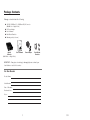
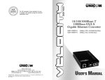
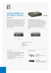
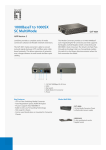
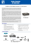
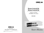
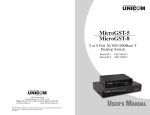
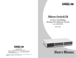
For full coverage of your warranty, be sure
to register your product using the enclosed
registration card.
10/100/1000Base-T
1000Base-SX/LX
Gigabit Ethernet Converter
GEP-5300TF-C
GEP-5400TF-C
908 Canada Court
City of Industry, CA 91748 U.S.A.
Phone: 626.964.7873 or 800.346.6668 Fax: 626.964.7880
www.unicomlink.com
e-mail: [email protected]
©UNICOM 2009. UNICOM and “A Network Systems Solution” are trademarks of UNICOM Electric, Inc.
All rights reserved. Specifications subject to change without notice.
Rev: 06.09
1000Base-T/SX (SC/MM/550m)
1000Base-T/LX (SC/SM/10km)
Rev. 2.0
USER’S MANUAL
Package Contents
Package contents include the following:
■ 10/100/1000Base-T to 1000Base-SX/LX Converter
(Multi-Mode or Single Mode)
■ DC Power Adapter
■ User’s Manual
■ Rack Mount Brackets
■ Warranty card (not shown)
Gigabit
User’s Manual
Converter
(Multi-Mode or Single Mode)
Power Adapter
Rack Mount
Brackets
IMPORTANT: If any piece is missing or damaged, please contact your
local dealer or reseller for service.
For Your Records
Product Name:
Serial Number:
Date of Purchase:
Purchased from:
Notes:
1
10
Product Specifications
Standard Compliance: IEEE 802.3 10/100/1000Base-T Gigabit Ethernet
IEEE 802.3 1000Base-SX/LX Gigabit Ethernet
Protocol:
CSMA/CD
Interface:
(1) 10/100/1000Base-T, Shielded RJ-45 Jack
(1) 1000Base-SX/LX, Dual SC connector
Cable distance:
10/100/1000Base-T
Cat. 5e or 6: up to 100m.
1000Base-SX: Multi-mode fiber
50/125µm (550m)
62.5/125µm (550m)
1000Base-LX: Single Mode fiber
9/125µm (10Km)
LED Indicators:
Power, Speed, Link/Activity (copper and fiber),
Full-Duplex (copper), Full-Duplex/collision (fiber)
Power Supply:
External power adapter 9V DC/700mA (min.)
Operating Temperature: 0˚C to 45˚C
Operating Humidity:
10% - 90% RH
EMI:
FCC Class A, CE Mark
Enclosure:
Metal
Dimensions:
120mm x 85mm x 26mm (L x W x H)
Warranty:
Limited Lifetime
Introduction
Congratulations on purchasing a quality UNICOM product.
Unicom’s VELOCITY Series represents the newest, most advanced
generation of signal conversion technology.
Unicom’s Giga Fiber Converter is a cost- effective solution for the
conversion of 10/100/1000Base-T (Auto MDI/MDIX) and pure 1000
Base-T to 1000Base-SX/LX cabling. It can be slotted into a multiconverter chassis that enhances your network flexibility. It can also be
used as a stand-alone converter.
The Giga Fiber Converter will allow you to extend the cabling distance of
your 10/100/1000Base-T (Auto MDI/MDIX) or pure 1000 Base-T
network up to 550m for multi-mode fiber or 10 kilometers for singlemode fiber. This Converter uses the most popular fiber cabling
connectors: SC multi- mode fiber connector and SC single-mode fiber
connector.
The Modular Giga Fiber Converters provides one Fiber connector for fiber
optic cable and one Ethernet RJ-45 port (Auto MDI/MDIX) for
10/100/1000Base-T copper cable or pure 1000 Base-T copper cable
connections. There are DIP- switches to set the operation mode for UTP,
Fiber ports and link lost forwarding function.
FCC Statement
This equipment has been tested and found to comply with the limits for a class B device, pursuant
to part 15 of the FCC rules. These limits are designed to provide reasonable protection against
harmful interference in a commercial installation. This equipment generates, uses and can
radiate radio frequency energy and, if not installed and used in accordance with instructions, may
cause harmful interference with radio communications. Operation of this equipment in a
residential area is likely to cause harmful interference, in which case, the user will be required to
correct the interference at the user’s expense.
9
2
Key Features
Cabling
Standards:
• Twisted-pair segments can be Unshielded Twisted Pair (UTP) or
Shielded Twisted Pair (STP) cabling. The cable must comply with the
IEEE 802.3 10/100/1000Base-T standard for Category 5e/6. The
cable between the converter and the link partner (switch, hub,
workstation, etc.) must be 100 meters (328 ft.) or less in length.
IEEE
IEEE
IEEE
IEEE
IEEE
802.3 10BASE-T
802.3u 100BASE-TX
802.3ab 1000BaseT,
802.3z 1000BaseSX/LX standards
802.3x Flow Control and Back pressure
LED Indicators: Power (Green)
UTP SPD: 1000Mbps /100Mbps / 10Mbps
Lnk/Act: UTP /FIBER
FDX: UTP: Full-Duplex mode / Half-Duplex or Link down
FIBER: Full-Duplex mode / Link down
Connector:
Fiber: Duplex SC
RJ-45 Socket: CAT-5e (10/100/1000Mbps) Twisted Pair
cable Auto MDI/MDI-X and Auto-Negotiation Function
Support
• Fiber segments using Single Mode connectors must use 9/125µm
Single Mode fiber cable. The maximum link distance in full duplex
operation is 10 Kilometers (6.2 miles). The maximum link distance
in half duplex operation is 412 meters (1352 ft).
• The maximum distance of fiber segments using Multi-Mode
connectors measures 550 meters (1804 ft.) with 50/125µm or
62.5/125µm Multi-Mode fiber cable.
Network Connection
Fiber parameters:
Fiber Core: Multi-Mode (62.5/125um, 50/125um)
Single-Mode (9/125um)
Wavelength: 850nm(Multi-mode),
1310nm(Single-mode)
Fiber Distance: 550m (Multi-Mode Fiber)
10km (Single-Mode Fiber)
A. Select the appropriate length Category 5e or 6 twisted pair cable.
Connect one end of the twisted pair cable to the RJ-45 connector
on the converter and the other end of twisted pair cable to the RJ45 connector on any 10/100/1000Base-T device.
B. Connect one end of a fiber jumper to the SC connector on this
converter and the other end of the fiber jumper to the SC
connector on the other 1000Base-SX/LX device.
Link Loss Forward:
Copper to Fiber: If copper port link down, then media
converter will forced fiber to link down.
Fiber to Copper: If Fiber port link down, the media
converter will forced copper port to link down.
C. Attach the power adapter DC jack to the converter. Verify that the
Power LED is on.
D. Verify that the UTP “LK/ACT” LEDs light when cable connection is
installed correctly. Verify that Fiber “LK/ACT” LED blinks to indicate
network activity.
Troubleshooting
• Verify that you are using the right power adapter, DC 5V, 2A
(minimum). Using a power adapter with DC output greater than 5V
could result in damage to the unit and/or personal injury.
• Confirm the proper UTP/Fiber cable is being used. The Single Mode
converter must use Single Mode fiber optic cable.
3
8
Installing Converters into Chassis
Follow the steps below to install modular converters into the 10 space
Converter Chassis (pn: FEP-593110).
A. Remove the blank bracket from the chassis by rotating screw
counterclockwise. Put the blank bracket aside.
B. Open the rack mount bracket kit. The kit contains two rack mount
brackets and four screws.
Hardware Description
The Front Panel
The Front Panel of the 10/100/1000T to 1000SX/LX converters
consists of one RJ-45 Port ( Auto MDI/MDIX ) one fiber 1000BaseSX/LX Port and 6 LED Indicators (SPD, LK/ACT, FDX, Fiber LK/ACT,
FDX/COL and PWR ).
10/100/1000T
SPD
C. Use a screwdriver to attach the rack mount ears to both sides of
the modular converter.
PWR
100Base-SX
1 2 3
ON
LK/ACT
FDX/COL
Auto MDI/MDIX
GEP-5300TF-C
10/100/100
0T
10/100/1000T
SPD
100Base-S
Auto MDI/M
Multi-Mode
550m
SPD
PWR
1000Base-LX
X
DIX
1 2 3
ON
Auto MDI/MDIX
D. Install the modular converter by inserting it into the chassis
guides and sliding it in until it stops. Press it firmly to seat the
chassis power plug into the modular converter receptacle.
GEP-5400TF-C
LK/ACT
FDX/COL
10km
Single Mode
Ports
• Copper Port: RJ-45 Port (Auto MDI/MDIX), the Ethernet RJ-45 will
features Auto-Sensing for 10/100/1000Base-T connections and
Auto MDI/MDIX which is basically an auto crossover feature. This
means you can connect to another Switch or workstation without
changing to a crossover cable.
• Fiber Port: This port is for the 1000Base-SX/LX connection and is
available in the SC format in Multi- and Single mode.This fiber port
does not support auto-negotiation.
The Rear Panel
E. Gently push the thumbscrews in and turn clockwise to tighten.
Do not over tighten.
DC IN
The rear panel contains a power socket. This power socket accepts
DC9V voltage and minimum 0.7A supplied current.
7
4
LED Indicators
DIP Switch Description
There are six diagnostic LEDs located on the front panel of these
converters. The LEDs provide real-time information on system status.
The indicators include SPD, LK/ACT, FDX, Fiber LK/ACT, FDX/COL and
PWR. The following table provides describes these LEDs:
The DIP-switch is used to configure operation mode for LLF (Link
Lost Forwarding) and operation mode for Copper/Fiber port. The
default value of Dipswitch is OFF.
10/100/1000Base-T to 1000Base-FX converter module
No.
Status
Description
• The converter is supplied with
suitable power.
1
Off
On
LLF enabled
LLF disabled
Green
Amber
Off
• Current UTP Speed is 1000Mbps
• Current UTP Speed is 100Mbps
- •
Current UTP Speed is 10Mbps
2
Off
On
Switch Coverter Mode
Pure Converter Mode
3
On
Blinking
Off
Green
-
• Unit is connected with a link
• Unit is transmitting data
• No device attached
Off
On
Reserved
Reserved
On
Off
Orange
-
• The UTP port is in full-duplex mode.
• Half-duplex mode/no device attached
On
Blinking
Off
Green
-
• Unit is connected with a link
• Unit is transmitting data
• No device attached
On
Off
Amber
-
• The UTP port is in full-duplex mode
• No device attached
LED
Status
Color
Description
PWR
On
Green
SPD
On
On
( speed )
LK/ACT
( UTP )
FDX ( UTP )
LK/ACT
( Fiber )
FDX/COL
( Fiber )
Link Lost Forwarding: When LLF is enabled, it will allow copper port
link failure to be reported to the Fiber side and will also allow Fiber
link failure to be reported to the copper side. Therefore, a link loss
forward feature is provided on both copper and Fiber sides.
Pure Converter mode: When Pure Converter mode is enabled (ON),
the switch operates with the minimum latency. The transmission flow
does not wait until an entire frame is ready but instead forwards the
received data immediately after being received. The TP should be
forced at 1000M in this application.
When the DIP-Switch is in Switch Converter mode (OFF), the
converter function is the same as a Switch Hub.
[Note]
1) Do not change the DIP-switch setting when the copper or fiber port is
transmitting or receiving data. It may cause data error.
2) Power off, then power on when changing the DIP-switch setting.
5
6