1
ADJUSTABLE SPEED DRIVE NETWORK INTERFACE
ICC
INDUSTRIAL CONTROL COMMUNICATIONS, INC.
ETH-100
ETHERNET COMMUNICATIONS INTERFACE
FOR THE TOSHIBA 7-SERIES AND 9-SERIES
ADJUSTABLE SPEED DRIVES
April 2002
ICC #10449-1.100-000
Introduction
Thank you for purchasing the ICC, Inc. ETH-100 Ethernet Communications Interface
for the Toshiba 7-Series and 9-Series Adjustable Speed Drives. Before using the
ETH-100 interface, please familiarize yourself with the product and be sure to
thoroughly read the instructions and precautions contained in this manual. In
addition, please make sure that this instruction manual is delivered to the end user of
the drive units with which the ETH-100 interface is connected, and keep this
instruction manual in a safe place for future reference or drive/interface inspection.
This instruction manual describes the device specifications, wiring methods,
maintenance procedures, supported functions and usage methods for the ETH-100
Ethernet communications interface.
In conjunction with this manual, the following manuals are supplied by Toshiba, and
are essential both for ensuring a safe, reliable system installation as well as for
realizing the full potential of the ETH-100 interface:
•
•
•
•
•
Toshiba TOSVERT VF-S7 Series Instruction Manual
Toshiba TOSVERT VF-S9 Series Instruction Manual
Toshiba TOSVERT VF-A7 Series Instruction Manual
Toshiba G7 Series Operation Manual
Toshiba VF-S7 Industrial Inverter Serial Communications Option Manual
If you do not have copies available of the documents relevant to your installation,
please contact Toshiba or your local Toshiba distributor to obtain them, or copies
may be downloaded from http://www.tic.toshiba.com (subject to availability).
Before continuing, please take a moment to ensure that you have received all
materials shipped with your kit. These items are:
•
•
•
External ETH-100 interface in DIN rail mountable case
2 meter DB9-RJ45 MMI port cable (part number 10425)
This manual
1
ETH-100 Ethernet Interface User's Manual
Part Number 10449-1.100-000
Printed in U.S.A.
©2001-2002 Industrial Control Communications, Inc.
All rights reserved
Industrial Control Communications, Inc. reserves the right to make changes and
improvements to its products without providing notice.
Notice to Users
INDUSTRIAL CONTROL COMMUNICATIONS, INC.’S PRODUCTS ARE NOT
AUTHORIZED FOR USE AS CRITICAL COMPONENTS IN LIFE-SUPPORT
DEVICES OR SYSTEMS. Life-support devices or systems are devices or systems
intended to sustain life, and whose failure to perform, when properly used in
accordance with instructions for use provided in the labeling and user's manual, can
be reasonably expected to result in significant injury.
No complex software or hardware system is perfect. Bugs may always be present in
a system of any size. In order to prevent danger to life or property, it is the
responsibility of the system designer to incorporate redundant protective mechanisms
appropriate to the risk involved.
2
Usage Precautions
Operating Environment
•
Please use the ETH-100 only when the ambient temperature of the
environment into which the ETH-100 is installed is within the following
specified temperature limits:
Operation: -10 ∼ +50°C (+14 ∼ +122°F)
Storage: -40 ∼ +85°C (-40 ∼ +185°F)
•
•
Avoid installation locations that may be subjected to large shocks or vibrations.
Avoid installation locations that may be subjected to rapid changes in
temperature or humidity.
Installation • Wiring
•
•
•
•
•
•
Do not touch charged parts of the drive such as the terminal block while the
drive’s CHARGE lamp is lit. A charge will still be present in the drive’s internal
electrolytic capacitors, and therefore touching these areas may result in an
electrical shock. Always turn all drive input power supplies OFF, and wait at
least 5 minutes after the CHARGE lamp has gone out before connecting
communication cables or motor wiring.
Proper ground connections are vital for both safety and signal reliability
reasons. For proper grounding procedures, please refer to the section in this
manual pertaining to grounding (section 4).
Route all communication cables separate from the drive’s input/output power
wiring.
To avoid the possibility of electric shock due to leakage currents, always
ground the drive’s E/GND terminal and the motor. To avoid misoperation, do
not connect the ETH-100’s GND terminal to either of the above-mentioned
grounds or any other power ground.
When making connections between the ETH-100 and the drives, do not use
cables that exceed 5 meters in length.
For further drive-specific precaution, safety and installation information, please
refer to the appropriate Toshiba documentation supplied with your drive.
Other Precautions
•
•
•
•
Internal drive EEPROMs have a limited life span of write cycles. Observe all
precautions contained in this manual and Toshiba manuals regarding which
drive registers safely may and may not be repetitively written to.
Do not touch or insert a rod or any other item into the ETH-100’s case while
power is applied, as this may lead to electrical shock or device damage.
Commission the disposal of the ETH-100 to a specialist.
Because the ETH-100 derives its control power from the connected drives,
removing power to all connected drives will also cause the ETH-100 to lose
power.
3
TABLE OF CONTENTS
1.
Mechanical Diagrams........................................................................... 6
1.1
1.2
1.3
Enclosure .........................................................................................................6
Mounting Clip ...................................................................................................7
External Interface .............................................................................................8
2.
Feature Summary ................................................................................. 9
3.
Installing The Interface ...................................................................... 12
3.1
3.2
Installation for G7 Drives ................................................................................12
Installation for S7, S9 and A7 Drives..............................................................13
4.
Grounding ........................................................................................... 15
5.
Environmental Specifications ........................................................... 16
6.
Maintenance And Inspection ............................................................. 17
7.
Storage And Warranty........................................................................ 18
7.1
7.2
Storage ..........................................................................................................18
Warranty ........................................................................................................18
8.
Console Configuration....................................................................... 19
8.1
RS232 ............................................................................................................19
8.1.1
Requirements..........................................................................................19
8.1.2
Connection..............................................................................................19
8.1.3
Application Configuration ........................................................................19
8.2
Telnet .............................................................................................................21
8.2.1
Requirements..........................................................................................21
8.2.2
Connection..............................................................................................21
8.2.3
Application Configuration ........................................................................21
8.3
Command Overview.......................................................................................22
8.4
Console Configuration Backup .......................................................................24
9.
LED Indicators .................................................................................... 25
9.1
9.2
9.3
Module and Ethernet Indicators......................................................................25
Drive Connector Indicators.............................................................................25
MMI Connector Indicators ..............................................................................26
10.
Modbus TCP/IP ................................................................................... 27
10.1
10.2
10.3
Drive Channel Access ................................................................................27
Supported Modbus Functions .....................................................................27
Modbus/Drive Register Mappings ...............................................................28
4
10.4
10.5
10.6
10.7
10.8
10.9
11.
Register Remap Function ...........................................................................29
ASD Scan Registers ...................................................................................30
Modbus Programmable Pointer Registers ..................................................30
Register Access Notes ...............................................................................31
Performance Tips .......................................................................................32
Exceptions and Troubleshooting.................................................................34
Embedded Web Server .......................................................................35
11.1
Setup Page.................................................................................................36
11.2
Modbus Page .............................................................................................37
11.3
Channels Page ...........................................................................................38
11.3.1 Channel Select........................................................................................39
11.3.2 ASD Scan Register Configuration ...........................................................40
11.3.3 Programmable Pointer Registers Configuration ......................................41
11.3.4 Drive Test Commands.............................................................................42
12.
Firmware Updates...............................................................................43
12.1
Requirements .............................................................................................43
12.2
Connection .................................................................................................43
12.3
Using The RFU Utility .................................................................................44
12.3.1 Required Files .........................................................................................44
12.3.2 First-time configuration............................................................................44
12.3.3 Transmitting Firmware Files ....................................................................46
12.4
Wrap-Up .....................................................................................................46
13.
Notes ....................................................................................................48
5
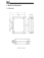
1. Mechanical Diagrams
1.1 Enclosure
(All units are in inches)
6
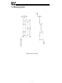
1.2 Mounting Clip
(All units are in inches)
7
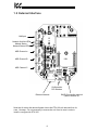
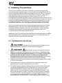
1.3 External Interface
MMI port
Network Link/Act LEDs
Module Status /
Network Status LEDs
ASD Channel A
ASD Channel B
ASD Channel C
Configuration
DIP switches
Ethernet Network
SHIELD grounding terminal
(refer to Section 4).
Note that for clarity the above diagram shows the ETH-100 unit removed from its
case. However, it is not necessary to remove the unit from its case in order to
install or configure the ETH-100.
8
2. Feature Summary
The ETH-100 interface provides a wide array of network data access and drive
control features. Combined with the flexible configuration and standard 10BaseT
Ethernet/Internet connectivity, this allows powerful networked control and monitoring
systems to be designed. This in turn provides easy and direct data transfer
capabilities to PLCs, PC-based control systems and a wide array of
manufacturing/ERP and plant control software packages.
Network
IEEE 802.3 10BaseT Ethernet compliant. Shielded RJ45 connector accepts
standard CAT5-type 8-conductor unshielded twisted-pair (UTP) patch cables.
Drive Connections
The ETH-100 provides support for simultaneous connection of three Toshiba 7-series
or 9-series drives via the drives’ common serial (aka logic level) communication
ports. All drives share a common IP address. Drive connections use the same
standard RJ45 style 8-conductor UTP patch cables: any standard CAT5 Ethernet
cable (found in most electronics stores) 5 meters or less in length can be used to
connect the ETH-100 to the drives.
Power Supply
Self-contained. Powered directly from the connected drives. Drives can be
connected to the ETH-100 on any channel (A, B or C) in any order or combination.
When more than 1 drive is connected to the unit, the ETH-100 will draw its control
power from the drive with the highest power supply voltage.
Supported Protocols
Current support for Schneider Electric Modbus TCP/IP, release 1.0. Conformance
Class 0 and partial Class 1 compliant. Allows up to 8 simultaneous Modbus TCP/IP
client connections.
Text-Based Console Configuration
The unit can be configured via a simple text-based console interface, available locally
over RS232 by using the enclosed MMI cable or remotely over Ethernet via a telnet
session.
Embedded Web Server
Unit configuration and drive monitoring and control are also provided via an
embedded web server using the HTTP protocol. The ETH-100’s web server feature
provides direct access and control via standard web browsers such as Microsoft
Internet Explorer and Netscape Navigator.
9
Drive AutoScan Algorithm
Connections to the drives are automatically established and continuously monitored.
No drive configuration needs to be performed to connect the ETH-100 to the drives.
Just plug it in – it’s that simple.
User-Configurable Scan Registers
In order to provide faster access to internal drive data, the user has the ability to
program up to 8 ASD registers per channel to be locally mirrored within the ETH-100.
This greatly increases the speed with which accesses to these registers can be made
by the network master.
Programmable Pointer Registers
16 Modbus programmable pointer registers are provided to allow “bundling” of
disassociated registers. This allows registers which may be scattered around the
Modbus register map to be accessed by issuing only 1 Modbus transaction request.
When combined with the user-configurable scan registers, this feature provides
accessibility of any combination of ASD registers with fast response in a single
Modbus transaction.
Indicators
•
•
•
•
•
1 green “LNK” LED that is on whenever a valid Ethernet connection is detected.
1 red “ACT” LED that flashes whenever data is transferred across the Ethernet
network.
1 bicolor red/green “MS” LED that indicates module status information.
1 bicolor red/green “NS” LED that indicates network status information.
2 green LEDs on each of the drive communication connectors and on the MMI
port connector.
Refer to section 9 for more detailed information about the LED indicators and their
meanings.
Selectable Grounding
Switch SW1 #2 allows the ground plane to be split into 2 different sections: one for
the main control circuitry and another for the Ethernet network connector shield and
associated magnetics. The latter ground point is accessible for external termination
via the GND screw terminal located on the bottom of the unit. Refer to section 4 for
more information related to grounding.
MMI Port Connector
RS232-level. Use the DB9-to-RJ45 MMI cable supplied with the ETH-100 kit to
interface with the unit for either console-based configuration or flash firmware
downloading.
10
Field-Upgradeable
As new firmware becomes available, the ETH-100 unit can be upgraded in the field
by the end-user. Refer to section 12 for more information.
Versatile 3-Way DIN-Rail Mounting System
The unit’s enclosure is provided with a mounting clip attached to the rear of the unit.
This clip allows the unit to be mounted 3 different ways:
•
For DIN rail mounting, snap the mounting clip onto a standard DIN rail, and
then snap the unit enclosure onto the clip’s retaining tabs. This allows easy
removal or repositioning of the unit on the DIN rail during wiring.
•
For panel mounting, the mounting clip can be bolted directly to a flat panel via
the two bolt holes at the top and bottom of the clip. Refer to section 1.2 for
mounting clip mechanical details. Once the mounting clip is securely
attached to the panel, the unit enclosure can be snapped onto the clip’s
retaining tabs.
•
For fixed DIN rail mounting, a combination of the above two techniques can
be employed. First, snap the mounting clip onto a DIN rail and position it in its
desired location. Then, the mounting clip can be bolted to the DIN rail support
panel, securing it in place. Lastly, the unit can be snapped onto the fixed
mounting clip.
In all cases, the unit can be easily unsnapped from the mounting clip to temporarily
provide easier access to the configuration switches or network connector.
11
3. Installing The Interface
The ETH-100 connects to each drive via the drive’s common serial (logic level)
communication port, typically located on either the main drive control board (G7), on
the front of the drive enclosure under a small snap-on cover (A7, S9), or on the righthand side of the drive enclosure under a small snap-on cover (S7). Although no
drive parameters need to be configured in order to use the ETH-100, it is
advantageous to check that the drive’s common serial communication data rate is set
to its maximum speed. Because the ETH-100 will communicate to each drive only at
the drive’s configured data rate, this will provide the fastest response time for driveto-network data transfers. For information on checking the drive’s common serial
communication data rate, refer to the appropriate manual supplied with your drive.
Note that the common serial communication parameters of each drive are handled
independently by the ETH-100, which means that different drive families may be
connected to different channels of the unit in any combination, and that the drives
connected to each channel may simultaneously communicate to the unit at
completely different baud rates, parity settings, etc.
Installation of the ETH-100 Ethernet interface should only be performed by a qualified
technician familiar with the maintenance and operation of the connected drives. To
install the ETH-100, complete the following steps:
3.1 Installation for G7 Drives
1.
2.
CAUTION!
Verify that all input power sources to the drives to be
connected have been turned OFF and are locked and tagged out.
DANGER!
Wait at least 5 minutes for the drive’s electrolytic
capacitors to discharge before proceeding to the next step. Do not touch any
internal parts with power applied to the drive, or for at least 5 minutes after
power to the drive has been removed. A hazard exists temporarily for
electrical shock even if the source power has been removed. Verify that the
CHARGE LED has gone out before continuing the installation process.
3. Attach the mounting clip and unit enclosure in your desired manner (refer to page
11 for more information).
4. Remove the drive’s front cover / open the drive’s cabinet door (refer to the
appropriate drive manual for instructions how to do this).
5. The drive’s Electronic Operator Interface (EOI) can communicate with the drive
via either the RS485/RS232 channel (CNU1/CNU1A) or the common serial
channel (CNU2/CNU2A). Because the ETH-100 uses the common serial
channel, the EOI must be configured to use the RS485/RS232 channel. If the
drive to be connected is currently using CNU2 (on the drive control board) and
CNU2A (on the EOI), then this connection must first be switched over to CNU1
(on the drive control board) and CNU1A (on the EOI). Refer to Toshiba’s
documentation for any precautions or notices regarding this connection change.
12
If the EOI is already connected via the RS485/RS232 channel, then no change is
required.
6. Connect the drive’s common serial communication port (CNU2) to one of the
channels (A, B or C) of the ETH-100 with the communication cable
(communication cable is not included with the interface kit). When choosing
cables for this connection, standard 24 AWG category 5 (CAT5) unshielded
twisted-pair (UTP) 8-conductor cables found in Ethernet networks in most office
environments can be used. The maximum allowable length for these cables is 5
meters. Although there are many varieties and styles of CAT5 UTP cables
available, ICC strongly recommends using only high-quality cables from reputable
manufacturers to guarantee optimal noise immunity and cable longevity. Ensure
that each end of the cable is fully seated into the modular connector, and route
the cable such that it is located well away from any drive input power or motor
wiring. Also take care to route the cable away from any sharp edges or positions
where it may be pinched.
7. Reinstall the drive’s front cover / close the drive’s cabinet door.
8. Repeat steps 1, 2, 4, 5, 6 and 7 to connect other drives as needed.
9. Connect the Ethernet network cable to the shielded RJ45 connector marked
“Network” on the bottom of the unit. If a ground cable is going to be used, attach
the ground cable to the screw terminal marked “GND” on the bottom side of the
unit (refer to section 4). Ensure that the network cable is fully seated into the
modular connector, and route the cable such that it is located well away from any
drive input power or motor wiring. Also take care to route the cable away from
any sharp edges or positions where it may be pinched.
10. Take a moment to verify that the ETH-100 and all network cables have sufficient
clearance from drives, motors, or power-carrying electrical wiring.
11. Turn the power sources to all connected drives ON, and verify that the drives
function properly. If the drives do not appear to power up, or do not function
properly, immediately turn power OFF. Repeat steps 1 and 2 to remove all
power from the drives. Then, verify all connections. Contact ICC or your local
drive distributor or manufacturer for assistance if the problem persists.
3.2 Installation for S7, S9 and A7 Drives
CAUTION!
1.
Verify that all input power sources to the drives to be
connected have been turned OFF and are locked and tagged out.
2.
Wait at least 5 minutes for the drive’s electrolytic
capacitors to discharge before proceeding to the next step. Do not touch any
internal parts with power applied to the drive, or for at least 5 minutes after
power to the drive has been removed. A hazard exists temporarily for
electrical shock even if the source power has been removed. Verify that the
CHARGE LED has gone out before continuing the installation process.
DANGER!
3. Attach the mounting clip and unit enclosure in your desired manner (refer to page
11 for more information).
13
4. Remove the drive’s common serial communication port cover (refer to the
appropriate drive manual for instructions how to do this). Do not discard this
cover, as it should be reinstalled to minimize contamination of the port’s electrical
contacts if the interface is ever disconnected from the drive.
5. Connect the drive’s common serial communication port to one of the channels (A,
B or C) of the ETH-100 with the communication cable (communication cable is
not included with the interface kit). When choosing cables for this connection,
standard 24 AWG category 5 (CAT5) unshielded twisted-pair (UTP) 8-conductor
cables found in Ethernet networks in most office environments can be used. The
maximum allowable length for these cables is 5 meters. Although there are many
varieties and styles of CAT5 UTP cables available, ICC strongly recommends
using only high-quality cables from reputable manufacturers to guarantee optimal
noise immunity and cable longevity. Ensure that each end of the cable is fully
seated into the modular connector, and route the cable such that it is located well
away from any drive input power or motor wiring. Also take care to route the
cable away from any sharp edges or positions where it may be pinched.
6. Repeat steps 1, 2, 4 and 5 to connect other drives as needed.
7. Connect the Ethernet network cable to the shielded RJ45 connector marked
“Network” on the bottom of the unit. If a ground cable is going to be used, attach
the ground cable to the screw terminal marked “GND” on the bottom side of the
unit (refer to section 4). Ensure that the network cable is fully seated into the
modular connector, and route the cable such that it is located well away from any
drive input power or motor wiring. Also take care to route the cable away from
any sharp edges or positions where it may be pinched.
8. Take a moment to verify that the ETH-100 and all network cables have sufficient
clearance from drives, motors, or power-carrying electrical wiring.
9. Turn the power sources to all connected drives ON, and verify that the drives
function properly. If the drives do not appear to power up, or do not function
properly, immediately turn power OFF. Repeat steps 1 and 2 to remove all
power from the drives. Then, verify all connections. Contact ICC or your local
drive distributor or manufacturer for assistance if the problem persists.
14
4. Grounding
Grounding is of particular importance for reliable, stable operation. Communication
system characteristics may vary from system to system, depending on the system
environment and grounding method used. The ETH-100 interface is provided with a
“GND” screw terminal on the bottom of the unit. This “GND” terminal constitutes an
effective “chassis ground”, and is directly connected to the metallic housing of the
shielded RJ45 Ethernet network connector and to the appropriate locations on its
integrated isolation magnetics.
This chassis ground plane is physically separate from the ETH-100’s control logic
ground plane, which is directly referenced to the CC (control common) terminal on
the connected drives. Switch SW1 #2 on the ETH-100 unit, however, provides a
method to selectively connect these 2 ground planes together.
When switch SW1 #2 is ON (switch in the “down” position when looking at the bottom
of the ETH-100 unit end-on), the ETH-100’s control logic ground plane and chassis
ground plane are connected together. In this configuration, no external GND wire
should be connected to the unit’s GND terminal. In this case, the chassis ground
plane is directly connected to the drives’ CC reference, and Toshiba typically
recommends that the CC reference of the drives not be connected to earth ground.
Refer to your drive’s instruction manual for specific information about the CC terminal
and ground connections.
In some high-noise environments or under unusual wiring conditions, it may be
possible to obtain improved Ethernet communication characteristics by referencing
the ETH-100’s “chassis ground” to a localized earth ground. In these cases, place
switch SW1 #2 in the OFF (up) position and connect the GND screw terminal to an
appropriate ground connection.
Please be sure to consider the following general points for making proper ground
connections:
Grounding method checkpoints
1. Make all ground connections such that no ground current flows through the case
or heatsink of a connected drive.
2. Do not connect the ETH-100’s GND terminal to a power ground or any other
potential noise-producing ground connection (such as a drive’s “E” terminal).
3. Do not make connections to unstable grounds (paint-coated screw heads,
grounds that are subjected to inductive noise, etc.)
15
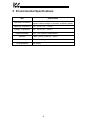
5. Environmental Specifications
Item
Specification
Operating Environment
Indoors, less than 1000m above sea level, do not
expose to direct sunlight or corrosive / explosive gasses
Operating Temperature
-10 ∼ +50°C (+14 ∼ +122°F)
Storage Temperature
-40 ∼ +85°C (-40 ∼ +185°F)
Relative Humidity
20% ∼ 90% (without condensation)
Vibration
5.9m/s2 {0.6G} or less (10 ∼ 55Hz)
Grounding
Cooling Method
Selectable split ground planes
Self-cooled
16
6. Maintenance And Inspection
Preventive maintenance and inspection is required to maintain the ETH-100 Ethernet
interface in its optimal condition, and to ensure a long operational lifetime.
Depending on usage and operating conditions, perform a periodic inspection once
every three to six months. Before starting inspections, always turn off all power
supplies to connected drives, and wait at least five minutes after each drive’s
“CHARGE” lamp has gone out.
DANGER!
Do not touch any internal parts with power applied
to the drives, or for at least 5 minutes after power to the drives has been
removed. A hazard exists temporarily for electrical shock even if the source
power has been removed.
Inspection Points
•
Check that the dust covers for all unused RJ45 ports are seated firmly in their
connectors.
•
Check that the drive and Ethernet communication cables are not loose. Reseat if
necessary.
•
Check that there are no defects in any attached grounding wire terminal crimp
points. Visually check that the crimp points are not scarred by overheating.
•
Visually check all wiring and cables for damage. Replace as necessary.
•
Clean off any accumulated dust and dirt.
•
If use of the ETH-100 is discontinued for extended periods of time, apply power at
least once every two years and confirm that the unit still functions properly.
•
Do not perform hi-pot tests on the drives or ETH-100 interface, as they may
damage the units.
Please pay close attention to all periodic inspection points and maintain a good
operating environment.
17
7. Storage And Warranty
7.1 Storage
Observe the following points when the ETH-100 interface is not used immediately
after purchase or when it is not used for an extended period of time.
•
Avoid storing the unit in places that are hot or humid, or that contain large
quantities of dust or metallic dust. Store the unit in a well-ventilated location.
•
When not using the unit for an extended period of time, apply power at least once
every two years and confirm that it still functions properly.
7.2 Warranty
The ETH-100 Ethernet Communications Interface is covered under warranty by ICC
for a period of 12 months from the date of installation, but not to exceed 18 months
from the date of shipment from the factory. For further warranty or service
information, please contact Industrial Control Communications or your local
distributor.
18
8. Console Configuration
The ETH-100 typically requires configuration prior to communicating on an Ethernet
network. Configuration is achieved via a text-based console interface, accessible
over an RS232 serial channel and a telnet interface. The following are the factoryset values of the most important Ethernet parameters:
IP Address ................ 10.0.0.101
Netmask ................... 255.255.255.0
Default Gateway ....... 10.0.0.2
If these parameters do not match with your network settings, they will need to be
modified.
8.1 RS232
The console is accessible via an RS232 interface for direct connection to a
computer’s serial (COM) port. This is performed by using the included DB9-RJ45
cable to connect the ETH-100’s MMI port to the computer’s serial port. This will
typically be the initial configuration channel, as the telnet interface can only be
accessed once the network parameters have already been established and the
device is communicating on the Ethernet network.
8.1.1 Requirements
All that is needed is a computer with a standard serial (COM) port containing some
sort of communications software (such as HyperTerminal, shipped with Microsoft
Windows operating systems) and the included MMI cable (ICC part number #10425).
Any communications software and PC will work, provided they support ASCII
communications at 38.4kbaud.
8.1.2 Connection
The ETH-100 ships from the factory with a dust cover installed in the MMI port. To
minimize contamination of the port’s electrical contacts, keep this dust cover in place
whenever the MMI port is not in use.
Connect the RJ45 end of the MMI cable to the MMI port, and connect the other end
to the computer’s serial port. Make sure that switch SW1 #1 is in the “OFF” position.
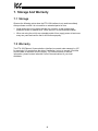
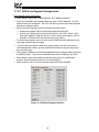
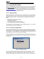
8.1.3 Application Configuration
As previously mentioned, any PC communication software and PC serial port can be
used. The software configuration example given here will be for Windows
HyperTerminal communicating via COM1.
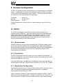
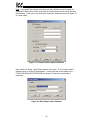
Figure 1 shows the “Connect To” tab of the properties window for COM1. Figure 2
shows the window that appears when “Configure” is selected in the “Connect To” tab.
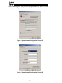
Figure 3 shows the “Settings” tab of the properties window. Most of these settings
19
are their default values: usually the only change needed is the “Bits Per Second”
setting shown in Figure 2.
Figure 1: HyperTerminal Configuration Screen #1
Figure 2: HyperTerminal Configuration Screen #2
20
Figure 3: HyperTerminal Configuration Screen #3
8.2 Telnet
The console is also accessible via a Telnet interface for remote administration over
Ethernet once the unit is communicating on the network. The Telnet console uses
well-known port 23. Note that although only 1 telnet console session can be active at
any given time, the telnet console and RS232 console operate independently and can
be used simultaneously.
8.2.1 Requirements
All that is needed is a computer with telnet software that can access the ETH-100
over the Ethernet network. Telnet software is typically included as a standard
component of Microsoft Windows and other PC operating systems.
8.2.2 Connection
No special connections are required, other than the PC running the Telnet application
must be able to logically connect to the ETH-100 to be configured.
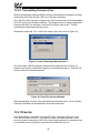
8.2.3 Application Configuration
Although any software vendor’s Telnet client application can be used, the
configuration example given here will use the Microsoft Windows Telnet application.
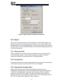
To start the Telnet application, simply type “telnet” at either a DOS (command)
prompt or in the “Start…Run” window. Once the telnet client screen opens, the
target device can be accessed simply by typing “open” at the Telnet prompt with the
ETH-100’s IP address as an argument. Refer to Figure 4.
21
Figure 4: Telnet Menu
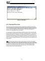
8.3 Command Overview
The console provides standard access and configuration methods for the various
network parameters and application configuration parameters supported by the ETH100. The number and type of supported console commands may vary with different
console version and application version firmware. This section will present an
overview of the supported console commands.
It is important to note that unless otherwise indicated, each of these commands will
become effective immediately after it has been successfully entered. This may have
several repercussions; for example, if you change the IP address of the device via
the Telnet console, then you will lose the telnet connection to the device (as it was a
connection to the old IP address) and therefore must re-connect to the console if you
wish to continue changing parameters. Also note that the console commands are not
case-sensitive.
Help: This command shows the console version and an overview of all available
commands. As indicated in the returned help information, typing “Help <command>”
with a specific command will return help information specific to that command. Refer
to Figure 5 for the help command output via Telnet. All further display screens
shown in this manual will be from Telnet, although they will look identical when
accessed via the serial channel (MMI port).
22
Figure 5: "Help" Command Via Telnet
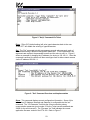
Echo: “Echo ON” (default setting) will echo typed characters back to the user.
“Echo OFF” will disable the echoing of typed characters.
Set: The “Set” command actually encompasses several subcommands, each of
which allows setting a different configuration parameter. To set a parameter, two
arguments are required: the parameter’s name and the value to set it to. Figure 6
shows an example of changing the IP address of a device to 192.168.1.1. After this
command is entered, the device will then reconfigure itself to allow network access
via the IP address 192.168.1.1.
Figure 6: "Set" Command Overview and Implementation
Show: This command displays current configuration information. Some of this
information (IP Address, Netmask and Gateway) is configurable via the “set”
command. The “I/O Parameter” field lists the current console’s primary
communication parameter (port number 23 for the Telnet console and baud rate
38400 for the serial console). The “Firmware Ver” field indicates the current
application firmware version of the ETH-100. Refer to Figure 7.
23
Figure 7: "Show" Command Overview
8.4 Console Configuration Backup
The console configuration is backed up in the ETH-100’s battery backed SRAM. This
allows the console configuration to be restored upon power-up. Although the battery
inside the ETH-100 is rated to last approximately 10 years with no other power
supplied to the unit (and longer when power is supplied to the unit), it may eventually
require replacement at some point in the product’s lifetime. When this happens, the
IP address, netmask, and default gateway settings will be lost upon power-down.
To ensure that these important settings can be recovered in the event of a battery
failure, it is recommended that you record your IP address, netmask, and gateway
settings in the notes section (section 13) of this manual for future reference.
24
9. LED Indicators
The ETH-100 unit contains many different LED indicators, each of which conveys
important information about the status of the unit, connected drives and Ethernet
network. These LEDs and their functions are summarized here.
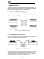
9.1 Module and Ethernet Indicators
The module and Ethernet indicators are located between the MMI port and the
Channel A drive port. Figure 8 indicates the functions of these LEDs (perspective is
with MMI port to the left of the LEDs).
ACT (Ethernet ACTivity)
NS (Network Status)
Flashes red when network
activity is detected
Currently reserved
LNK (Ethernet LiNK)
MS (Module Status)
Solid green when valid
network link exists
Currently reserved
Figure 8: Module and Ethernet Indicators
9.2 Drive Connector Indicators
Each drive communication channel RJ45 connector contains two integrated green
LEDs. Figure 9 indicates the functions of these LEDs.
Network Access
Drive Link
Blinks in 0.1s-long bursts
when channel is accessed
by Ethernet client
Solid green when a logical
connection exists with the
attached drive
Figure 9: Drive Connector Indicators
The Network Access indicator is useful for confirming that a specific drive channel is
being accessed correctly by the Ethernet client (master), while the Drive Link
indicator provides an easy method of determining that the ETH-100 and drive are
successfully exchanging data, independent of Ethernet activity.
25
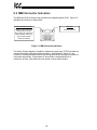
9.3 MMI Connector Indicators
The MMI port RJ45 connector also contains two integrated green LEDs. Figure 10
indicates the functions of these LEDs.
Active Sockets Indicator
Reserved
Blinks in 0.25s-long bursts
separated by 2s of OFF
time: number of consecutive
blinks indicates number of
open TCP/IP sockets
(client connections)
Currently reserved
Figure 10: MMI Connector Indicators
The Active Sockets indicator is helpful in determining how many TCP/IP sockets are
currently allocated to Ethernet clients (masters). As indicated in Figure 10, the
number of currently-allocated sockets can be determined by counting the number of
concurrent short blinks. Each stream of short blinks is terminated by 2s of
continuous off time, after which the next stream of short blinks begins.
26
10. Modbus TCP/IP
The ETH-100 interface supports Schneider Electric’s Modbus TCP/IP protocol,
release 1.0. The ETH-100 is conformance class 0 and partial class 1 compliant, and
allows up to 8 simultaneous Modbus TCP/IP client connections (sockets). Socket
timeouts are set to 30s, which means that if a particular open socket experiences no
activity for more than 30s, then the interface assumes that the client has experienced
some sort of unexpected problem, and the ETH-100 will close that socket.
10.1 Drive Channel Access
Each specific drive channel (Channel A, Channel B and Channel C) is accessed via
the “Unit Identifier” (UI) field of a Modbus TCP/IP packet. Drive channel A is
accessed when the UI field is set to “1”, channel B is accessed when the UI field is
set to “2”, and channel C is accessed when the UI field is set to “3”. Any other UI
setting is invalid and will result in a GATEWAY PATH UNAVAILABLE exception
(Modbus TCP/IP exception code 0A).
10.2 Supported Modbus Functions
The ETH-100 interface supports the Modbus TCP/IP function codes indicated in
Table 1.
Table 1: Supported Modbus TCP/IP Functions
Function Code
3
6
16
Function
Read multiple registers
Write single register
Write multiple registers
27
Class
0
1
0
10.3 Modbus/Drive Register Mappings
The ETH-100’s Modbus TCP/IP interface acts as a relatively straightforward network
gateway for the attached drives. By and large, Modbus TCP/IP holding registers (04
registers) are directly mapped to corresponding Toshiba drive registers (also referred
to as “communication numbers” in Toshiba documentation) with a direct 1-to-1
correspondence. The relationship between Modbus TCP/IP holding registers and
their Toshiba drive register counterparts is as follows:
Modbus TCP/IP holding register = Toshiba drive register + 1
This means that in order to access a specific Toshiba drive register, simply add 1 to it
and access that Modbus TCP/IP holding register. The reason for this offset is due to
the fact that Toshiba drive registers begin at number 0, while Modbus holding
registers begin at number 1.
As an example of this relationship, let’s say that we would like to access parameter
“Acceleration Time #1” on a Toshiba S9 drive connected to the ETH-100. According
to the relevant Toshiba Serial Communications Manual, we see that “Acceleration
Time #1” resides at drive register number 0x0009 (note hexadecimal notation). By
adding 1 to this value, we obtain 0x000A (1010), which is the Modbus holding register
that must be used to access this drive parameter.
In order to avoid any possible confusion regarding this register-mapping scheme, this
manual will always explicitly use the terms “drive register” or “Modbus register” where
the intention may not be clear. If the term “register” is used alone, then “Modbus
register” will be the intended meaning by default.
With only 2 exceptions (discussed below), the ETH-100 does not in any way modify
or otherwise alter valid register access requests originating from the Modbus TCP/IP
client. By adhering to this design parameter, the availability and interpretation of any
Modbus registers is entirely determined by the attached drive(s). In this way, the
ETH-100 allows itself to become virtually “transparent” on the network, essentially
allowing the Modbus TCP/IP client to carry on a dialog directly with the drives. This
technique also allows a wide array of drive families and capacity classes to be
implemented without compatibility concerns.
The two exceptions to the previous paragraph are as follows:
1. Register remapping option. The ETH-100 can be configured to alter a portion
of the mapping relationship for register-limited clients. Refer to section 10.4
for a discussion pertaining to register remapping.
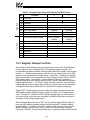
2. The status register (drive register 0xFE01) typically does not contain any
information indicating whether the attached drive is faulted or not. For ease
of client application programming, therefore, the ETH-100 will indicate a
connected drive’s faulted status in bit #14 of this register (normally, this bit is
”reserved” by the drive). Refer to Table 2 for an example modified status
register from an S9 drive. Because the specific format of the status register
depends on the drive family and firmware implementation, please refer to your
drive’s Serial Communications Manual for the exact structure of this bitmapped register. NOTE: This added feature is only available if drive register
0xFE01 is configured to be one of the selectable scan registers (refer to
section 10.5 for more information regarding scan registers).
28
Table 2 : Example Status Word (ASD Register 0xFE01) Format
Low Byte
High Byte
Bit
Function
15
14
13
12
11
10
9
8
7
Reserved
Faulted status
Reserved
Reserved
Reserved
Run / stop status
Forward / reverse status
Jog status
DC injection braking status
6
5
4
3
2
1
0
Accel / decel #1/#2 status
Reserved
Reserved
Reserved
Reserved
Reserved
Reserved
0
1
--
Not faulted
Faulted
----
Stopped
Forward
Not jogging
Not DC injection
braking
#1
Running
Reverse
Jogging
DC injection
braking
#2
-------
10.4 Register Remap Function
Some Modbus client software does not allow access to more than 10,000 Modbus
holding registers. As the standard ETH-100 mapping provides a simple 1-to-1
correspondence between Modbus holding registers and ASD registers (ASD register
number + 1 = Modbus holding register number), this can cause certain critical ASD
registers to be inaccessible from these clients. Specifically, Toshiba drives typically
place communication control registers and status registers in the 0xFAxx to 0xFFxx
ASD register region. For example, “Communication Frequency Command” is
typically assigned to ASD register number 0xFA01, which is accessible via Modbus
holding register 0xFA01 + 1 = 0xFA02, which is 64002 in decimal. As this Modbus
holding register number is higher than 10,000, this register would not be accessible
via register-limited clients unless the ETH-100 performed register remapping.
“Remap OFF” (default setting) does not modify the register mapping between the
ASD registers and the Modbus holding registers: a simple 1-to-1 correspondence
exists. “Remap ON” modifies the ASD register mapping slightly to allow access to
the drive’s critical control and status registers by Modbus clients that are limited to
accessing 10,000 holding registers max.
With the Remap parameter set to “ON”, the ETH-100 will add 0xF000 (6144010) to
incoming ASD register accesses between 0x0A00 and 0x0FFF (Modbus holding
registers 0x0A01 – 0x1000). In this way, register-limited clients need only write to
Modbus holding register 0x0A02 (256210) to set the Communication Frequency
Command. Similarly, “Current Output Frequency” is typically located at ASD register
29
0xFD00 (Modbus holding register 0xFD01), which can therefore be accessed via
Modbus holding register 0x0D01 (332910) when register remapping is enabled.
When register remapping is enabled, only accesses to Modbus registers 0x0A01 –
0x1000 are affected: the normal locations for the critical control and status registers
remain unaffected and can still be accessed (i.e. Communication Frequency
Command will be updated via writes to either register 0x0A02 or 0xFA02: both will
write to ASD register 0xFA01).
Refer to section 11.2 for further information regarding configuration of the register
remap selection.
10.5 ASD Scan Registers
Scan registers are used to define ASD registers that the user wishes to access
quickly. ASD registers that are configured to be scan registers will have their data
mirrored locally on the ETH-100. Requesting the data from or writing data to an
ASD register that is set up to be a scan register will take less network time because
the ETH-100 simply accesses a local value instead of initiating a transaction with the
ASD to process the data.
Refer to section 11.3.2 for further information regarding configuration of the scan
registers.
10.6 Modbus Programmable Pointer Registers
Programmable pointer registers (PPR) allow the user to access non-consecutive
Modbus registers with only one Modbus transaction. Modbus register locations
0xFC00 ~ 0xFC0F are reserved by the ETH-100 to access the registers defined in
the PPR section of the "channels" page of the ETH-100's embedded web server. For
example, if you would like to continuously read the data from ASD registers 0xFD00,
0xFE01, 0xFE04 and 0xFE05, the standard Modbus register configuration would
require 3 read commands to be issued: one reading 1 Modbus register starting at
register 0xFD01, one reading 1 Modbus register starting at register 0xFE02, and one
reading 2 Modbus registers starting at register 0xFE05. To conserve network
bandwidth and speed processing time, however, the programmable pointer registers
can be used to allow the same information to be accessed, but by only issuing 1
command which reads 4 Modbus registers.
To configure this function, enter the register numbers of the Modbus registers you
would like to continuously access into the PPR section of the embedded web server's
"channels" page (refer to section 11.3.3). For example, we could set PPR register
location 0xFC00 to a value of 0xFD01 (the first Modbus register number we want to
access), register location 0xFC01 to a value of 0xFE02, register location 0xFC02 to a
value of 0xFE05, and register location 0xFC03 to a value of 0xFE06. The 4 registers
that are to be monitored can now be accessed simply by issuing 1 Modbus holding
register read command with a length of 4 starting from Modbus register location
0xFC00. The returned data will be the data obtained from ASD registers 0xFD00,
0xFE01, 0xFE04, and 0xFE05 (in that order). IMPORTANT: Note that PPR values
refer to MODBUS registers. That is, Modbus registers = ASD registers + 1.
30
Refer to section 11.3.3 for more information regarding programmable pointer
registers and their configuration.
10.7 Register Access Notes
This section contains some helpful notes and reminders that further detail the
interface unit and drives’ behavior.
•
Remember that drive registers and Modbus registers are offset by 1.
Accessing the lowest valid Modbus register (0x0001) will access drive register
0x0000.
•
The data values written to ASD registers that are configured as scan registers
are not checked for range. Therefore, if a value outside the valid range of
adjustment for a “write” scan register is written, the write will be acknowledged
by the ETH-100, but the drive will not accept the invalid value.
•
All register writes use the drive’s RAM / EEPROM data write (“W”) command
except for those registers configured to be “write” scan registers, which use
the drive’s RAM data write (“P”) command. For all writes that target the
drive’s EEPROM, be sure to follow Toshiba’s guidelines regarding the number
of times a specific register can be written without risk of EEPROM damage.
•
For those drive families which do not have an explicit FREQUENCY MODE
SELECTION or COMMAND MODE SELECTION parameter setting
corresponding to the common serial channel (i.e. S7 and S9), remember that
bits #14 and #15 of the communication command register (drive register
0xFA00) must be set to enable network frequency and network commands,
respectively.
•
For safety, when a new “write” scan register is entered, the ETH-100 will set
that register’s initial local value to 0.
•
Attempting to access a programmable pointer register that has not been
configured with a register value (i.e. the “Points To…” field shows up blank on
the configuration web page) will result in a Modbus 02 exception (ILLEGAL
DATA ADDRESS).
31
10.8 Performance Tips
This section offers several configuration tips which can help to optimize the
performance of communications with the ETH-100 and attached drives.
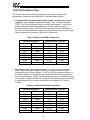
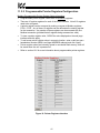
1. Configure Modbus programmable pointer registers to also be drive scan
registers. In the example configuration shown in Table 3, Modbus registers
FC00 ~ FC07 are configured to point to the ASD scan registers. In this case, a
Modbus transaction beginning at address FC00 with a length of 8 can be
processed extremely fast. Of course, pointer registers can still be accessed if
they are not configured as scan registers, but the transactions are slower, as they
require transferring the request to the drive for processing.
Table 3: Efficient Scan/PPR Configuration
ASD Scan Registers
Modbus Pointer Registers
Register
R/W Value
Register
Points To…
FA01
FA00
FD00
FE01
FC90
FE03
FE42
FA22
Read
Read
Read
Read
Read
Read
Read
Read
FC00
FC01
FC02
FC03
FC04
FC05
FC06
FC07
FA02
FA01
FD01
FE02
FC91
FE04
FE43
FA23
2. Don’t leave a gap in the access sequence. For optimal network response,
make sure all of the pointer registers that you are going to access are also
configured to be ASD scan registers. The ETH-100 is most effective when all of
the pointer registers that are going to be accessed are also ASD scan registers.
In the example shown in Table 4, the high-speed processing of a Modbus register
read starting at register 0xFC00 with a length of 8 will be delayed by the necessity
to interact with the drive to obtain the values of drive registers 0xFC90 and
0xFE03.
Table 4: Inefficient Scan/PPR Configuration
ASD Scan Registers
Modbus Pointer Registers
Register
R/W Value
Register
Points To…
FA01
FA00
FD00
FE01
Read
Read
Read
Read
FE42
FA22
Read
Read
FC00
FC01
FC02
FC03
FC04
FC05
FC06
FC07
FA02
FA01
FD01
FE02
FC91
FE04
FE43
FA23
32
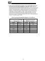
3. Group read and write registers together in the programmable pointer list
and access them with separate Modbus commands. The ETH-100 can
process read requests and write requests faster when they are grouped together
rather than the master having to issue multiple transactions to access disjoint
registers. This is especially true when the registers to be accessed are also
configured as ASD scan registers. Pointer registers can be accessed in any
combination of starting register and length. In the setup below, you would
optimize ETH-100 efficiency by having two Modbus transactions: one read
request with a length of 6 starting at register FC00, and one write request with a
length of 2 starting at register FC08.
Table 5: Grouping Read and Write Registers In The PPR List
Modbus Pointer Registers
(Also configured to be ASD READ
scan registers)
Modbus Pointer Registers
(Also configured to be ASD
WRITE scan registers)
Register
Points To…
Register
Points To…
FC00
FC01
FC02
FC03
FC04
FC05
FC06
FC07
FE03
FE06
FD01
FE02
FC91
FE04
FC08
FC09
FC0A
FC0B
FC0C
FC0D
FC0E
FC0F
FA02
FA01
33
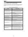
10.9 Exceptions and Troubleshooting
Although by no means exhaustive, Table 6 provides some possible causes behind
some of the most common errors experienced when using the Modbus TCP/IP
interface.
Table 6: Troubleshooting Reference
Problem
Register addressing is off by 1
Modbus TCP/IP client cannot establish
communication with the ETH-100
Possible Cause
Refer to Section 10.3 for Modbus/drive mapping
•
•
•
•
Drive does not respond to network
commands / frequency command
•
•
Ensure at least one of the connected drives is powered on
Check that the drive and Ethernet communication cables
are fully seated into their respective communication ports
Check the Ethernet communication parameters (IP
address, etc.)
Check drive’s frequency mode and command mode
selection parameters
Where applicable, confirm the values of bits #14 and #15
of communication command word
Confirm that communication frequency command value is
between lower limit and upper limit frequencies
ILLEGAL FUNCTION exception
(Modbus exception code 01)
The indicated Modbus function is not supported: refer to section
10.2 for a list of supported functions
ILLEGAL DATA ADDRESS exception
(Modbus exception code 02)
The targeted drive register (or one in a group of targeted
registers) does not exist: check the drive’s supported register
list
ILLEGAL DATA VALUE exception
(Modbus exception code 03)
The value written was rejected by the drive as invalid: check the
value and drive setting range
•
NEGATIVE ACKNOWLEDGE exception
(Modbus exception code 07)
•
•
•
An attempt was made to write to a drive register while the
drive was running that does not accept writes while the
drive is running
An attempt was made to write to a read-only register
Confirm that the drive communication cable is fully seated
into the drive’s and ETH-100’s communication ports
Confirm that the drive communication cable is not routed
near the drive’s input power or motor wiring or any other
electrical noise-producing cables or equipment
GATEWAY PATH UNAVAILABLE
exception (Modbus exception code 0A)
Unit Identifier (UI) was invalid: UI must be 1 ∼ 3
GATEWAY TARGET DEVICE FAILED TO
RESPOND exception
(Modbus exception code 0B)
The targeted drive is not online or failed to respond:
•
Confirm that the targeted drive is powered-on
•
Confirm that the drive communication cable is fully seated
into the drive’s and ETH-100’s communication ports
•
Confirm that the drive communication cable is not routed
near the drive’s input power or motor wiring or any other
electrical noise-producing cables or equipment
34
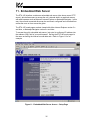
11. Embedded Web Server
The ETH-100 interface contains an embedded web server (also known as an HTTP
server), which allows users to access the unit’s internal data in a graphical manner
with web browsers such as Microsoft Internet Explorer or Netscape Navigator. In this
way, the unit and connected drives can be monitored, configured and controlled from
across the room or from across the globe.
The ETH-100’s web pages are best viewed with either Internet Explorer version 5.x
and later, or Netscape Navigator version 6.x and later.
To access the unit’s embedded web server, just enter its configured IP address into
the address (URL) field of your web browser. Surfing the ETH-100’s web pages is
the same as surfing the Internet’s world-wide web. Refer to Figure 11 for an
example.
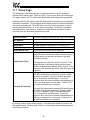
Figure 11: Embedded Web Server Access – Setup Page
35
11.1 Setup Page
The setup page is the initial page that is displayed when the unit’s IP address is
accessed via a web browser. Refer to Figure 11 for a screen shot of the setup page.
This page contains the ETH-100’s basic identification and configuration parameters:
Note that the ETH-100 requires valid user authentication whenever any configuration
information is modified. This will appear as a browser popup box that will request the
user name and password. The initial factory-set value for the username is “admin”,
and the password is blank (i.e. do not enter a password). Note that the username
and password are case-sensitive, and that the authentication will remain in effect
from that point until all browser windows are closed.
Firmware Version:
The current firmware version and the date it was created.
MAC Address:
The unique 48-bit Ethernet MAC ID for this device.
IP Address:
The IP address of the device (i.e.: 10.0.0.100).
Subnet Mask:
The Subnet Mask of the device (i.e.: 255.255.255.0).
Default Gateway:
The Default Gateway of the device (i.e.: 10.0.0.2).
Current Date & Time:
The current date and time set on the device.
To change the date: select the check box next to “Date”,
change the date to the desired values, and click Apply. If
the check box is not selected, the values in the date
fields will be ignored.
Update Date & Time:
To change the time: select the check box next to “Time”,
change the time to the desired value, and click Apply.
The time is represented in Military (24 hr.) format. If the
check box is not selected, the values in the time fields will
be ignored.
To change the authentication username for modifying the
ETH-100’s configuration parameters: select the check
box next to “Username”, type your desired user name
(max 10 characters), and click apply. You will be
required to enter the current username and password to
update your username to its new value. Contact ICC if
you cannot remember your username.
Username & Password:
To change the authentication password for modifying the
ETH-100’s configuration parameters: select the check
box next to “Password", type your desired password
(max 10 characters), and click apply. You will be
required to enter the current username and password to
update your password to its new value. Contact ICC if
you cannot remember your password.
By clicking “cancel” before clicking “apply”, all configuration data will be reset to the
last applied values. Clicking “help” will open a new browser window displaying some
basic help information.
36
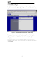
11.2 Modbus Page
The Modbus page can be accessed by clicking on the “Modbus” tab located at the
top of the browser window. Refer to Figure 12 for a screen shot of the Modbus Page.
Figure 12: Embedded Web Server Access – Modbus Page
This page provides access to the unit’s register remap function. To change the
register remap selection, simply click on the radio button corresponding to the
desired value. Refer to section 10.4 for a discussion pertaining to register
remapping.
This page also displays the number of Modbus TCP/IP sockets that have been
allocated by network clients. Refer to section 10 for more information about Modbus
TCP/IP sockets.
37
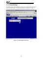
11.3 Channels Page
The Channels page can be accessed by clicking on the “Channels” tab located at the
top of the browser window. The initial page displayed will appear as in Figure 13
Figure 13: Channels Page Initial Screen
38
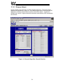
11.3.1 Channel Select
Use the “Select” drop-down box to select the desired channel. The screen that is
displayed will appear as in Figure 14. The channel select section on this screen will
display the currently selected channel and its online/offline status. A channel is
defined to be online if a logical connection has been made with an ASD connected to
that channel.
Figure 14: Channels Page After Channel Selection
39
11.3.2 ASD Scan Register Configuration
Scan Register Setup Information:
•
•
•
•
•
•
•
•
Scan register values refer to ASD registers, NOT Modbus registers.
There are 8 possible scan register values for each of the 3 channels. Not all 8
values need to be configured. The ETH-100 will only mirror those scan registers
that have a displayed value.
Each active scan register must be configured as read or write.
! A read scan register will be continuously polled from the ASD.
! A write scan register will be continuously written to the ASD. When a new
write scan register is added to the list, or when a write scan register value is
changed, its internal write value will be set to 0 for safety.
To clear a scan register value, the user must CLEAR the value displayed on the
web page interface and click apply.
To add a new scan register value in an empty location, the user must enter a
valid hexadecimal number, provide read/write information using the drop-down
box, and click apply.
Scan register values that are already displayed can be changed without providing
a read/write value. The previous read/write value will be retained in this case.
Scan register values and read/write values are stored in non-volatile flash
memory, and will be saved when the unit is powered off.
Refer to section 10.5 for more information about ASD scan registers.
Figure 15: ASD Scan Register Interface
40
11.3.3 Programmable Pointer Registers Configuration
Modbus Programmable Pointer Register Setup Information:
•
•
•
•
•
•
•
Programmable pointer register values refer to MODBUS registers.
There are 16 pointer registers for each of the three channels. Not all 16 registers
need to be configured.
A pointer register can be accessed by making a request to Modbus registers
FC00 ~ FC0F. Any of these 16 registers can be defined as the starting register
for the transaction. Any number of these registers can be accessed with one
Modbus transaction (provided that all registers being accessed are valid).
To clear a pointer register value, CLEAR the value displayed on the web page
interface and click apply.
To add a new pointer register value in an empty location, enter a valid non-zero
hexadecimal number (0000 is an illegal MODBUS address) and click “Apply”.
Pointer register values are internally stored in nonvolatile flash memory, and will
be saved when the unit is powered off.
Refer to section 10.6 for more information about programmable pointer registers.
Figure 16: Pointer Registers Interface
41
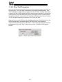
11.3.4 Drive Test Commands
Drive test commands can be used to test the communications between the ETH-100
and your ASD. To run the ASD connected to the currently selected channel, click
“Run” and submit a valid frequency command in the “FC” field. Clicking “Run” writes
a value of 0xC400 to ASD register 0xFA00 (communication command). Submitting a
valid frequency command writes that value to ASD register 0xFA01 (communication
frequency command). Note that the “FC” field expects floating-point values; entering
“53.43” will send a frequency command of 53.43 Hz to the drive.
Note that if you run the ASD from the embedded web server, bits #15 and #14 of the
ASD’s communication command register (0xFA00) are set, which indicates
“communication channel priority” to the drive. Local control of the drive will therefore
be disabled until you click ”Stop”, which writes a value of 0x0000 to ASD register
0xFA00.
Figure 17: Drive Test Commands Interface
42
12. Firmware Updates
The ETH-100’s embedded firmware resides in flash memory that can be updated in
the field. Firmware updates may be released for a variety of reasons, such as
custom firmware implementations, firmware improvements and added functionality as
a result of user requests.
ICC is continually striving to enhance the functionality and flexibility of our products,
and we therefore periodically release new embedded firmware to achieve these goals
and meet customer requests. Flash firmware files and all related documentation
(such as updated user manuals) can be downloaded as complete board support
packages (referred to as BSPs) from http://www.iccdesigns.com. It is suggested that
users check this Internet site prior to installation, and then periodically afterwards to
determine if new support packages have been released and are available to upgrade
their unit.
12.1 Requirements
Besides the new firmware file, firmware updates require a PC with a Windows
operating system (95/98/NT/2000) and a serial port, the Rabbit Field Utility
application (refer to section 12.3), and the MMI cable included with the ETH-100 kit
(ICC part #10425).
Please be sure to read the firmware release notes and updated user’s manual
(included with the BSP) prior to updating your firmware for any important notices,
behavior precautions or configuration requirements. For example, upgrading to a
new firmware version may reset user-configurable parameters (console settings) to
their factory-default value. If the release notes indicate this, be sure to manually
record all of your console settings prior to starting the update procedure for later
reentry.
12.2 Connection
The ETH-100 ships from the factory with a dust cover installed in the MMI port. To
minimize contamination of the port’s electrical contacts, keep this dust cover in place
whenever the MMI port is not in use.
IMPORTANT: Note that the ETH-100 will not be operating the system control and
communication application while its internal firmware is being updated. Therefore, be
sure to shut down the system to a known safe state prior to initiating the firmware
update procedure.
Connect the RJ45 end of the MMI cable to the MMI port, and connect the other end
to the computer’s serial port. Move switch SW1 #1 to the “ON” (down) position: this
will place the ETH-100 into the “firmware download” mode. Whenever switch SW1
#1 is “ON”, the ETH-100 can only download firmware to its flash: all other application
functions (such as Ethernet communications, console access etc.) will be disabled.
43
12.3 Using The RFU Utility
Support for downloading new application firmware to the ETH-100 is provided by the
free Rabbit Field Utility (RFU), which is a 32-bit application that runs on Microsoft
Windows platforms. The RFU utility can be downloaded from ICC’s home page at
http://www.iccdesigns.com. The remainder of this section will detail the RFU utility
configuration and firmware download procedures.
12.3.1 Required Files
When first downloaded, the RFU utility files are compressed into one self-extracting
.EXE distribution file. Create a folder (such as c:\RFU), place the distribution file in
this folder, and then execute it. This will extract the following files into that same
folder:
•
•
•
•
RFU.EXE (executable download utility)
RABFIELD.HLP (help file)
COLDLOAD.BIN (CPU bootstrap firmware)
PILOT.BIN (pilot BIOS firmware for downloading)
The distribution file is then unneeded and can be deleted if desired. To run the RFU
utility, double-click on the RFU.EXE file icon.
12.3.2 First-time configuration
The first time the RFU utility is run on a computer, several configuration items need
to be confirmed. These configuration items are retained in the computer’s registry
from that point on, so reconfiguration is not required unless certain parameters (such
as which serial port to use on the computer) are changed.
The two configuration items that need to be confirmed are the communications and
bootstrap loaders path. First, select the “Setup…Communications” menu item (refer
to Figure 18).
Figure 18: RFU Main Screen
The Communications Options window shown in Figure 19 then appears. Confirm
that the settings are as shown, with the possible exception of the “Comm Port”
setting, which depends on the COM port you are using. Click “OK” when complete.
44
Note: It is possible that certain computers may have difficulty communicating at a
sustained 115kbaud rate, which may result in communication errors during firmware
downloading. If this occurs, try setting the “baud rate” parameter shown in Figure 19
to a lower value.
Figure 19: Communications Options Window
Next, select the “Setup…Boot Strap Loaders” menu item. The “Choose Loaders”
window shown in Figure 20 then appears. Confirm that the correct paths to the
COLDLOAD.BIN and PILOT.BIN files are entered. Enter the correct paths if
necessary.
Figure 20: Boot Strap Loaders Window
45
12.3.3 Transmitting Firmware Files
When a board support package (BSP) has been downloaded and unzipped, the flash
firmware file will be the one with “.BIN” as its file name extension.
Once the RFU utility has been configured, the flash firmware files can be downloaded
to the ETH-100 by two different methods. The simplest way is to drag the application
firmware .BIN file’s icon and drop it onto the RFU utility’s main screen. This will
automatically initiate the download process.
Alternatively, select the “File…Load Flash Image” menu item (refer to Figure 21).
Figure 21: Load Flash Image Menu Selection
The flash image (.BIN file) selection window will then appear (refer to Figure 22).
Browse to the location of the flash image file to download and select it. Clicking “OK”
will then initiate the download process.
Figure 22: Flash File Selection Window
While downloading, the RFU utility will indicate the download status. Once complete,
summary information will be displayed in the bottom status bar.
12.4 Wrap-Up
Once downloading is complete, close the RFU utility, move switch SW1 #1 on the
ETH-100 unit back to the “OFF” (up) position to leave “firmware download” mode,
and cycle power momentarily to the unit by either powering down all connected drives
or momentarily removing all drive communication cables from the unit.
46
When the unit powers up again, it will be running the new application firmware. If the
new firmware version release notes indicated that any configuration parameters must
be reentered, reenter them again via the console. Also configure any new
parameters that are available to match your application requirements.
When completed with MMI port use, remove the MMI cable and replace the MMI port
dust cover to minimize contamination of the port’s electrical contacts.
47
13. Notes
48
ICC
INDUSTRIAL CONTROL COMMUNICATIONS, INC.
2202 Timberloch Place, Suite 210
The Woodlands, TX USA 77380-1163
Tel: [281] 367-3007 Fax: [281] 367-2177
World Wide Web http://www.iccdesigns.com
Printed in U.S.A