1
ADJUSTABLE SPEED DRIVE NETWORK INTERFACE
PBDP-110
PROFIBUS-DP COMMUNICATIONS INTERFACE
FOR THE TOSHIBA 7-SERIES AND 9-SERIES
ADJUSTABLE SPEED DRIVES
October 2001
ICC #10407-V1.00-000
Introduction
Thank you for purchasing the ICC PBDP-110 Profibus-DP Communications Interface
for the Toshiba 7-Series and 9-Series Adjustable Speed Drives. Before using the
PBDP-110 interface, please familiarize yourself with the unit and be sure to
thoroughly read the instructions and precautions contained in this manual. In
addition, please make sure that this instruction manual is delivered to the end user of
the drive units with which the PBDP-110 interface is connected, and keep this
instruction manual in a safe place for future reference or drive/interface inspection.
This instruction manual describes the device specifications, wiring methods,
maintenance procedures, supported functions and usage methods for the PBDP-110
Profibus-DP communications interface.
In conjunction with this manual, the following manuals are supplied by Toshiba, and
are essential both for ensuring a safe, reliable system installation as well as for
realizing the full potential of the PBDP-110 interface:
•
•
•
•
•
Toshiba TOSVERT VF-S7 Series Instruction Manual
Toshiba TOSVERT VF-S9 Series Instruction Manual
Toshiba TOSVERT VF-A7 Series Instruction Manual
Toshiba G7 Series Operation Manual
Toshiba VF-S7 Industrial Inverter Serial Communications Option Manual
If you do not have copies available of the documents relevant to your installation,
please contact Toshiba or your local Toshiba distributor to obtain them, or copies
may be downloaded from http://www.tic.toshiba.com (subject to availability).
Before continuing, please take a moment to ensure that you have received all
materials shipped with your kit. These items are:
•
•
•
External PBDP-110 interface in DIN rail mountable case
2 meter DB9-RJ45 MMI port cable (part number 10369)
This manual
1
PBDP-110 Profibus-DP Interface User's Manual
Part Number 10407-V1.00-000
Printed in U.S.A.
©2001-2002 Industrial Control Communications, Inc.
All rights reserved
Industrial Control Communications, Inc. reserves the right to make changes and
improvements to its products without providing notice.
Notice to Users
INDUSTRIAL CONTROL COMMUNICATIONS INC.’S PRODUCTS ARE NOT
AUTHORIZED FOR USE AS CRITICAL COMPONENTS IN LIFE-SUPPORT
DEVICES OR SYSTEMS. Life-support devices or systems are devices or systems
intended to sustain life, and whose failure to perform, when properly used in
accordance with instructions for use provided in the labeling and user's manual, can
be reasonably expected to result in significant injury.
No complex software or hardware system is perfect. Bugs may always be present in
a system of any size. In order to prevent danger to life or property, it is the
responsibility of the system designer to incorporate redundant protective mechanisms
appropriate to the risk involved.
2
Usage Precautions
Operating Environment
•
Please use the PBDP-110 only when the ambient temperature of the
environment into which the PBDP-110 is installed is within the following
specified temperature limits:
Operation: -10 ∼ +50°C (+14 ∼ +122°F)
Storage: -40 ∼ +85°C (-40 ∼ +185°F)
•
•
Avoid installation locations that may be subjected to large shocks or vibrations.
Avoid installation locations that may be subjected to rapid changes in
temperature or humidity.
Installation • Wiring
•
•
•
•
•
•
Do not touch charged parts of the drive such as the terminal block while the
drive’s CHARGE lamp is lit. A charge will still be present in the drive’s internal
electrolytic capacitors, and therefore touching these areas may result in an
electrical shock. Always turn all drive input power supplies OFF, and wait at
least 5 minutes after the CHARGE lamp has gone out before connecting
communication cables or motor wiring.
Proper ground connections are vital for both safety and signal reliability
reasons. For proper grounding procedures, please refer to the section in this
manual pertaining to grounding (section 4).
Route all communication cables separate from the drive’s input/output power
wiring.
To avoid the possibility of electric shock due to leakage currents, always
ground the drive’s E/GND terminal and the motor. To avoid misoperation, do
not connect the PBDP-110’s Profibus shield terminal to either of the abovementioned grounds or any other power ground.
When making connections between the PBDP-110 and the drives, do not use
cables that exceed 5 meters in length.
For further drive-specific precaution, safety and installation information, please
refer to the appropriate Toshiba documentation supplied with your drive.
Other Precautions
•
•
•
•
•
Do not touch or insert a rod or any other item into the PBDP-110’s case while
power is applied, as this may lead to electrical shock or device damage.
Commission the disposal of the PBDP-110 to a specialist.
Do not assign the same network address to more than one PBDP-110 station
in the same network. For a detailed explanation of station addressing, refer to
section 8.
Because the PBDP-110 derives its control power from the drive connected to
Channel A, removing power from that drive will also cause the PBDP-110 to
lose power, even if power is still applied to the drive connected to channel B.
When only 1 drive is connected to the PBDP-110, it must be connected to
Channel A.
3
TABLE OF CONTENTS
1.
Mechanical Diagrams........................................................................... 5
1.1
1.2
1.3
Enclosure .........................................................................................................5
Mounting Clip ...................................................................................................6
External Interface .............................................................................................7
2.
Feature Summary ................................................................................. 8
3.
Installing The Interface ...................................................................... 12
3.1
3.2
Installation for G7 Drives ................................................................................12
Installation for S7, S9 and A7 Drives..............................................................13
4.
Grounding ........................................................................................... 15
5.
Environmental Specifications ........................................................... 15
6.
Maintenance And Inspection ............................................................. 16
7.
Storage And Warranty........................................................................ 17
7.1
7.2
Storage ..........................................................................................................17
Warranty ........................................................................................................17
8.
Selecting the Profibus Network Address ......................................... 18
9.
Exchanged Data Structures............................................................... 20
9.1
9.2
9.3
Output (Control) Data Format.........................................................................20
Input (Status) Data Format.............................................................................23
Diagnostics ....................................................................................................26
10.
Parameter Register Access ............................................................... 27
10.1
10.2
10.3
10.4
Parameter Number / Action Output Words .................................................27
Parameter Number / Action Input Words ....................................................28
Parameter Access Procedure .....................................................................29
Register Access Error Codes......................................................................30
11.
Parameter Registers .......................................................................... 31
12.
MMI Port Use / GSD Files................................................................... 32
13.
Notes ................................................................................................... 33
4
1. Mechanical Diagrams
1.1 Enclosure
(All units are in inches)
5
1.2 Mounting Clip
(All units are in inches)
6
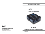
1.3 External Interface
MMI port
Address selection
DIP switches
Data_Exchange
LED
Profibus
network
connector
SHIELD grounding terminal
(refer to Section 4).
Drive “A” connector
Drive “B” Connector
Note that for clarity the above diagram shows the PBDP-110 unit removed from its
case. However, it is not necessary to remove the unit from its case in order to
install or configure the PBDP-110.
7
2. Feature Summary
The PBDP-110 interface provides a wide array of network data access and drive
control features. Combined with the flexible configuration and high-speed data
transfer capabilities of the Profibus network, this allows powerful networked control
and monitoring systems to be designed. Some of the main features provided by the
PBDP-110 which allow for this control and configurability are briefly described here:
Protocol
Profibus DP (Decentralized Periphery) as specified in European standard EN 50170.
The PBDP-110 can also co-exist simultaneously on networks using Profibus-FMS.
Network Baud Rates
Supports all Profibus baud rates from 9.6kbaud to 12Mbaud. The network baud rate
is automatically detected and continuously monitored during operation; no parameter
settings are necessary.
Drive Connections
The PBDP-110 provides support for simultaneous connection of two 7-series or 9series Toshiba drives. Both drives share a common Profibus station address. By
supporting 2 drives per interface, the maximum number of drives that can be
connected to 1 Profibus network segment without requiring repeaters increases from
31 (31 drives + 1 master) to 62 (31 PBDP-110 units + 1 master).
Power Supply
Self-contained. Powered directly from the drive connected to the Channel A
communications port. No external power supply devices or connections are required.
Isolation
The PBDP-110 has 3 separate isolated circuitry sections. Each drive is fully optically
isolated from each other, and both drives are optically isolated from the Profibus
network. By using optically isolated connections to the drives and the Profibus
network, grounding differential problems are eliminated and noise immunity
characteristics are greatly improved.
Drive AutoScan Algorithm
Connections to the drives are automatically established and continuously monitored.
No drive configuration needs to be performed to connect the PBDP-110 and
communicate via the Profibus network. Just plug it in – it’s that simple.
8
Global Control Functions
• Freeze mode: Input (monitor) data values are held constant within the PBDP-110
until the next “freeze” command or an “unfreeze” command is
received. Used primarily for synchronized monitoring of multiple
Profibus nodes.
• Sync mode:
Output (control) data values are held constant within the PBDP110 until the next “sync” command or an “unsync” command is
received. Used primarily for synchronized control of multiple
Profibus nodes.
• Clear_Data:
All output (control) data values are cleared to “0”.
Network Watchdog
A network watchdog function is always operating within the PBDP-110. In the event
of a disconnection from the Profibus network or loss of the network master, the
PBDP-110 can automatically switch any attached drives over to local control (if
selected at time of unit commissioning).
Indicators
•
•
•
1 green LED is provided to indicate when the PBDP-110 has achieved the
DATA_EXCHANGE state with the Profibus network master. This serves as a
convenient indicator that the Profibus master and PBDP-110 are configured
properly and are exchanging data.
1 green LED on the MMI interface port. The context is application-specific,
but under normal operation blinks at a 0.5Hz rate as a “heartbeat” indicator.
Also indicates data transfer when used with the Flashloader programming
utility.
1 green LED on each of the Channel A and Channel B drive connectors,
which indicate that the port is receiving power from the corresponding drive.
Profibus Network Connector
The network interface is a standard DB9 female connector with the following signals
provided:
Pin Number
3
4
5
6
8
9
1, 2, 7
Function
Profibus network “B” (positive) data line
RTS signal – direction control for fiber optic network
interface
DGND – power supply ground internally connected to the
interface board’s isolated ground
VP – power supply +5v internally connected to the
interface board’s isolated P5.
Profibus network “A” (negative) data line
RTS signal ground reference – internally connected to the
interface board’s isolated ground
No connection
9
In/Out
In/out
Out
In/out
-
In addition to the above signals, the metallic housing of the DB9 connector is
connected to the shield section of the interface board. The shield section is attached
to the metal ground terminal on the bottom of the unit, where a ground wire can be
attached to connect the Profibus network cable shield to ground. Refer to section 4
of this document for more information related to grounding.
Drive Network Connectors
TTL-level. Uses standard RJ-45 style 8-pin modular connectors. Any standard
category-5 Ethernet cable (found in most electronics stores) 5 meters or less in
length can be used to connect the PBDP-110 to the drives.
MMI Port Connector
RS232-level. Use the DB9-to-RJ-45 cable supplied with the PBDP-110 kit to
interface with the unit via the Flashloader programming utility (refer to section 12).
Input/Output Data
The PBDP-110 presents a module interface, supporting 2 different modules
depending on the number of drives connected to the unit.
If the PBDP-110 is configured for 1 drive (the Channel A drive), the interface’s cyclic
data sizes are fixed at 16 bytes of output (control) data configured as four 32-bit
words, and 24 bytes of input (status) data configured as six 32-bit words.
If the PBDP-110 is configured for both drives (Channel A and B), the interface’s
cyclic data sizes are fixed at 32 bytes of output (control) data configured as eight 32bit words, and 48 bytes of input (status) data configured as twelve 32-bit words.
Via these data structures, any data item (commands, monitor data and parameters)
available in the drive can be accessed. For detailed explanations of the format and
usage of this data, refer to sections 9 and 10 of this document.
Versatile 3-Way DIN-Rail Mounting System
The interface unit enclosure is provided with a mounting clip attached to the rear of
the unit. This clip allows the unit to be mounted 3 different ways:
•
For DIN rail mounting, snap the mounting clip onto a standard DIN rail, and
then snap the unit enclosure onto the clip’s retaining tabs. This allows easy
removal or repositioning of the unit on the DIN rail during wiring.
•
For panel mounting, the mounting clip can be bolted directly to a flat panel via
the two bolt holes at the top and bottom of the clip. Refer to section 1.2 for
mounting clip mechanical details. Once the mounting clip is securely
attached to the panel, the unit enclosure can be snapped onto the clip’s
retaining tabs.
•
For fixed DIN rail mounting, a combination of the above two techniques can
be employed. First, snap the mounting clip onto a DIN rail and position it in its
desired location. Then, the mounting clip can be bolted to the DIN rail support
10
panel, securing it in place. Lastly, the unit can be snapped onto the fixed
mounting clip.
In all cases, the unit can be easily unsnapped from the mounting clip to temporarily
provide easier access to the configuration switches or connectors.
11
3. Installing The Interface
The PBDP-110 connects to each drive via the drive’s common serial (logic level)
communication port, typically located on either the main drive control board (G7), on
the front of the drive enclosure under a small snap-on cover (A7, S9), or on the righthand side of the drive enclosure under a small snap-on cover (S7). Although no
drive parameters need to be configured in order to use the PBDP-110, it is
advantageous to check that the drive’s common serial communication data rate is set
to its maximum speed. Because the PBDP-110 will communicate to each drive only
at the drive’s configured data rate, this will provide the fastest response time for
drive-to-network data transfers. For information on checking the drive’s common
serial communication data rate, refer to the appropriate manual supplied with your
drive.
Note that this drive communication data rate setting is independent of the Profibus
network data rate, which is configured solely by the Profibus master station. Also
note that the common serial communication parameters of each drive are handled
independently by the PBDP-110, which means that different drive families may be
connected to different channels of the unit in any combination, and that the drives
connected to each channel may simultaneously communicate to the unit at
completely different baud rates, parity settings, etc.
Installation of the PBDP-110 Profibus interface should only be performed by a
qualified technician familiar with the maintenance and operation of the connected
drives. To install the PBDP-110, complete the following steps:
3.1 Installation for G7 Drives
1.
2.
CAUTION!
Verify that all input power sources to the drives to be
connected have been turned OFF and are locked and tagged out.
DANGER!
Wait at least 5 minutes for the drive’s electrolytic
capacitors to discharge before proceeding to the next step. Do not touch any
internal parts with power applied to the drive, or for at least 5 minutes after
power to the drive has been removed. A hazard exists temporarily for
electrical shock even if the source power has been removed. Verify that the
CHARGE LED has gone out before continuing the installation process.
3. Attach the mounting clip and unit enclosure in your desired manner (refer to page
10 for more information).
4. Remove the drive’s front cover / open the drive’s cabinet door (refer to the
appropriate drive manual for instructions how to do this).
5. The drive’s Electronic Operator Interface (EOI) can communicate with the drive
via either the RS485/RS232 channel (CNU1/CNU1A) or the common serial
channel (CNU2/CNU2A). Because the PBDP-110 uses the common serial
channel, the EOI must be configured to use the RS485/RS232 channel. If the
drive to be connected is currently using CNU2 (on the drive control board) and
12
CNU2A (on the EOI), then this connection must first be switched over to CNU1
(on the drive control board) and CNU1A (on the EOI). Refer to Toshiba’s
documentation for any precautions or notices regarding this connection change.
If the EOI is already connected via the RS485/RS232 channel, then no change is
required.
6. Connect the drive’s common serial communication port (CNU2) to “Channel A” of
the PBDP-110 with the communication cable (communication cable is not
included with the interface kit). When choosing cables for this connection,
standard 24 AWG category 5 (CAT5) unshielded twisted-pair (UTP) 8-conductor
cables found in Ethernet networks in most office environments can be used. The
maximum allowable length for these cables is 5 meters. Although there are many
varieties and styles of CAT5 UTP cables available, ICC strongly recommends
using only high-quality cables from reputable manufacturers to guarantee optimal
noise immunity and cable longevity. Ensure that each end of the cable is fully
seated into the modular connector, and route the cable such that it is located well
away from any drive input power or motor wiring. Also take care to route the
cable away from any sharp edges or positions where it may be pinched.
7. Reinstall the drive’s front cover / close the drive’s cabinet door.
8. Repeat steps 1, 2, 4, 5, 6 and 7 to connect another drive to “Channel B” on the
interface, if desired.
9. Connect the Profibus network cable to the DB9 connector marked “Network” on
the PBDP-110. If a ground cable is going to be used, attach the ground cable to
the terminal marked “Shield GND” on the bottom side of the PBDP-110 enclosure
(refer to section 4). Refer to the Profibus Specification for detailed network wiring
guidelines. Ensure that the Profibus network cable is tightly screwed onto the
DB9 connector, and route the cable such that it is located well away from any
drive input power or motor wiring. Also take care to route the cable away from
any sharp edges or positions where it may be pinched.
10. Take a moment to verify that the PBDP-110 and all network cables have
sufficient clearance from drives, motors, or power-carrying electrical wiring.
11. Configure the Profibus slave address via the DIP switches on the front of the
interface (refer to section 8).
12. Turn the power sources to all connected drives ON, and verify that the drives
function properly. If the drives do not appear to power up, or do not function
properly, immediately turn power OFF. Repeat steps 1 and 2 to remove all
power from the drives. Then, verify all connections. Contact ICC or your local
drive distributor or manufacturer for assistance if the problem persists.
3.2 Installation for S7, S9 and A7 Drives
1.
2.
CAUTION!
Verify that all input power sources to the drives to be
connected have been turned OFF and are locked and tagged out.
DANGER!
Wait at least 5 minutes for the drive’s electrolytic
capacitors to discharge before proceeding to the next step. Do not touch any
internal parts with power applied to the drive, or for at least 5 minutes after
13
power to the drive has been removed. A hazard exists temporarily for
electrical shock even if the source power has been removed. Verify that the
CHARGE LED has gone out before continuing the installation process.
3. Attach the mounting clip and unit enclosure in your desired manner (refer to page
10 for more information).
4. Remove the drive’s common serial communication port cover (refer to the
appropriate drive manual for instructions how to do this). Do not discard this
cover, as it should be reinstalled to minimize contamination of the port’s electrical
contacts if the interface is ever disconnected from the drive.
5. Connect the drive’s common serial communication port to “Channel A” of the
PBDP-110 with the communication cable (communication cable is not included
with the interface kit). When choosing cables for this connection, standard 24
AWG category 5 (CAT5) unshielded twisted-pair (UTP) 8-conductor cables found
in Ethernet networks in most office environments can be used. The maximum
allowable length for these cables is 5 meters. Although there are many varieties
and styles of CAT5 UTP cables available, ICC strongly recommends using only
high-quality cables from reputable manufacturers to guarantee optimal noise
immunity and cable longevity. Ensure that each end of the cable is fully seated
into the modular connector, and route the cable such that it is located well away
from any drive input power or motor wiring. Also take care to route the cable
away from any sharp edges or positions where it may be pinched.
6. Repeat steps 1, 2, 4 and 5 to connect another drive to “Channel B” on the
interface, if desired.
7. Connect the Profibus network cable to the DB9 connector marked “Network” on
the PBDP-110. If a ground cable is going to be used, attach the ground cable to
the terminal marked “Shield GND” on the bottom side of the PBDP-110 enclosure
(refer to section 4). Refer to the Profibus Specification for detailed network wiring
guidelines. Ensure that the Profibus network cable is tightly screwed onto the
DB9 connector, and route the cable such that it is located well away from any
drive input power or motor wiring. Also take care to route the cable away from
any sharp edges or positions where it may be pinched.
8. Take a moment to verify that the PBDP-110 and all network cables have
sufficient clearance from drives, motors, or power-carrying electrical wiring.
9. Configure the Profibus slave address via the DIP switches on the front of the
interface (refer to section 8).
10. Turn the power sources to all connected drives ON, and verify that the drives
function properly. If the drives do not appear to power up, or do not function
properly, immediately turn power OFF. Repeat steps 1 and 2 to remove all
power from the drives. Then, verify all connections. Contact ICC or your local
drive distributor or manufacturer for assistance if the problem persists.
14
4. Grounding
Grounding is of particular importance for reliable, stable operation. Communication
system characteristics may vary from system to system, depending on the system
environment and grounding method used. The PBDP-110 Profibus interface is
provided with a “Shield GND” terminal on the bottom of the unit. The “Shield GND”
terminal is directly connected to the metallic housing of the DB9 connector, which
should in turn be connected to the shield of the Profibus network cable through the
Profibus connector. To ground the network cable shield, therefore, connect a wire to
the Shield GND terminal, and then connect the other end of the wire to an
appropriate ground. For specific requirements regarding protective grounding and
the Profibus network, refer to the Profibus Standard (EN 50 170, part 1).
Please be sure to consider the following general points for making proper ground
connections:
Grounding method checkpoints
1. Make all ground connections such that no ground current flows through the case
or heatsink of a connected drive.
2. Do not connect the PBDP-110 Shield GND terminal to a power ground or any
other potential noise-producing ground connection (such as a drive’s “E”
terminal).
3. Do not make connections to unstable grounds (paint-coated screw heads,
grounds that are subjected to inductive noise, etc.)
5. Environmental Specifications
Item
Specification
Operating Environment
Indoors, less than 1000m above sea level, do not
expose to direct sunlight or corrosive / explosive gasses
Operating Temperature
-10 ∼ +50°C (+14 ∼ +122°F)
Storage Temperature
-40 ∼ +85°C (-40 ∼ +185°F)
Relative Humidity
20% ∼ 90% (without condensation)
Vibration
5.9m/s2 {0.6G} or less (10 ∼ 55Hz)
Grounding
Cooling Method
According to EN 50 170, part 1
Self-cooled
15
6. Maintenance And Inspection
Preventive maintenance and inspection is required to maintain the communication
interface in its optimal condition, and to ensure a long operational lifetime.
Depending on usage and operating conditions, perform a periodic inspection once
every three to six months. Before starting inspections, always turn off all power
supplies to connected drives, and wait at least five minutes after each drive’s
“CHARGE” lamp has gone out.
DANGER!
Do not touch any internal parts with power applied
to the drives, or for at least 5 minutes after power to the drives has been
removed. A hazard exists temporarily for electrical shock even if the source
power has been removed.
Inspection Points
•
Check that the dust covers for all unused RJ45 ports are seated firmly in their
connectors.
•
Check that the drive and network communication cables are not loose. Tighten /
reseat as necessary.
•
Where applicable, check that there are no defects in any attached grounding wire
terminal crimp points. Visually check that the crimp points are not scarred by
overheating.
•
Visually check all wiring and cables for damage. Replace as necessary.
•
Clean off any accumulated dust and dirt.
•
If use of the interface is discontinued for extended periods of time, apply power at
least once every two years and confirm that the unit still functions properly.
•
Do not perform hi-pot tests on the drives or interface, as they may damage the
units.
Please pay close attention to all periodic inspection points and maintain a good
operating environment.
16
7. Storage And Warranty
7.1 Storage
Observe the following points when the communication interface is not used
immediately after purchase or when it is not used for an extended period of time.
•
Avoid storing the unit in places that are hot or humid, or that contain large
quantities of dust or metallic dust. Store the unit in a well-ventilated location.
•
When not using the unit for an extended period of time, apply power at least once
every two years and confirm that it still functions properly.
7.2 Warranty
This communications interface is covered under warranty by ICC for a period of 12
months from the date of installation, but not to exceed 18 months from the date of
shipment from the factory. For further warranty or service information, please contact
Industrial Control Communications, Inc. or your local distributor.
17
8. Selecting the Profibus Network Address
The 8-position piano-style “Address” DIP switches accessible from the front of the
unit allow selection of the Profibus slave address. Switch positions #1 ∼ #7 select the
address. Switch position #8 is reserved for production test use, and should always
be kept in the “OFF” position. The PBDP-110 does not support the Profibus
“set_slave_address” service.
The address settings for the various switch configurations are as follows:
SW1
SW2
SW3
SW4
SW5
SW6
SW7
Addr
SW1
SW2
SW3
SW4
SW5
SW6
SW7
Addr
OFF
OFF
OFF
OFF
OFF
OFF
OFF
0
OFF
OFF
OFF
OFF
OFF
ON
OFF
32
ON
OFF
OFF
OFF
OFF
OFF
OFF
1
ON
OFF
OFF
OFF
OFF
ON
OFF
33
OFF
ON
OFF
OFF
OFF
OFF
OFF
2
OFF
ON
OFF
OFF
OFF
ON
OFF
34
ON
ON
OFF
OFF
OFF
OFF
OFF
3
ON
ON
OFF
OFF
OFF
ON
OFF
35
OFF
OFF
ON
OFF
OFF
OFF
OFF
4
OFF
OFF
ON
OFF
OFF
ON
OFF
36
ON
OFF
ON
OFF
OFF
OFF
OFF
5
ON
OFF
ON
OFF
OFF
ON
OFF
37
OFF
ON
ON
OFF
OFF
OFF
OFF
6
OFF
ON
ON
OFF
OFF
ON
OFF
38
ON
ON
ON
OFF
OFF
OFF
OFF
7
ON
ON
ON
OFF
OFF
ON
OFF
39
OFF
OFF
OFF
ON
OFF
OFF
OFF
8
OFF
OFF
OFF
ON
OFF
ON
OFF
40
ON
OFF
OFF
ON
OFF
OFF
OFF
9
ON
OFF
OFF
ON
OFF
ON
OFF
41
OFF
ON
OFF
ON
OFF
OFF
OFF
10
OFF
ON
OFF
ON
OFF
ON
OFF
42
ON
ON
OFF
ON
OFF
OFF
OFF
11
ON
ON
OFF
ON
OFF
ON
OFF
43
OFF
OFF
ON
ON
OFF
OFF
OFF
12
OFF
OFF
ON
ON
OFF
ON
OFF
44
ON
OFF
ON
ON
OFF
OFF
OFF
13
ON
OFF
ON
ON
OFF
ON
OFF
45
OFF
ON
ON
ON
OFF
OFF
OFF
14
OFF
ON
ON
ON
OFF
ON
OFF
46
ON
ON
ON
ON
OFF
OFF
OFF
15
ON
ON
ON
ON
OFF
ON
OFF
47
OFF
OFF
OFF
OFF
ON
OFF
OFF
16
OFF
OFF
OFF
OFF
ON
ON
OFF
48
ON
OFF
OFF
OFF
ON
OFF
OFF
17
ON
OFF
OFF
OFF
ON
ON
OFF
49
OFF
ON
OFF
OFF
ON
OFF
OFF
18
OFF
ON
OFF
OFF
ON
ON
OFF
50
ON
ON
OFF
OFF
ON
OFF
OFF
19
ON
ON
OFF
OFF
ON
ON
OFF
51
OFF
OFF
ON
OFF
ON
OFF
OFF
20
OFF
OFF
ON
OFF
ON
ON
OFF
52
ON
OFF
ON
OFF
ON
OFF
OFF
21
ON
OFF
ON
OFF
ON
ON
OFF
53
OFF
ON
ON
OFF
ON
OFF
OFF
22
OFF
ON
ON
OFF
ON
ON
OFF
54
ON
ON
ON
OFF
ON
OFF
OFF
23
ON
ON
ON
OFF
ON
ON
OFF
55
OFF
OFF
OFF
ON
ON
OFF
OFF
24
OFF
OFF
OFF
ON
ON
ON
OFF
56
ON
OFF
OFF
ON
ON
OFF
OFF
25
ON
OFF
OFF
ON
ON
ON
OFF
57
OFF
ON
OFF
ON
ON
OFF
OFF
26
OFF
ON
OFF
ON
ON
ON
OFF
58
ON
ON
OFF
ON
ON
OFF
OFF
27
ON
ON
OFF
ON
ON
ON
OFF
59
OFF
OFF
ON
ON
ON
OFF
OFF
28
OFF
OFF
ON
ON
ON
ON
OFF
60
ON
OFF
ON
ON
ON
OFF
OFF
29
ON
OFF
ON
ON
ON
ON
OFF
61
OFF
ON
ON
ON
ON
OFF
OFF
30
OFF
ON
ON
ON
ON
ON
OFF
62
ON
ON
ON
ON
ON
OFF
OFF
31
ON
ON
ON
ON
ON
ON
OFF
63
18
(continued…)
SW1
SW2
SW3
SW4
SW5
SW6
SW7
Addr
SW1
SW2
SW3
SW4
SW5
SW6
SW7
Addr
OFF
OFF
OFF
OFF
OFF
OFF
ON
64
OFF
OFF
OFF
OFF
OFF
ON
ON
96
ON
OFF
OFF
OFF
OFF
OFF
ON
65
ON
OFF
OFF
OFF
OFF
ON
ON
97
OFF
ON
OFF
OFF
OFF
OFF
ON
66
OFF
ON
OFF
OFF
OFF
ON
ON
98
ON
ON
OFF
OFF
OFF
OFF
ON
67
ON
ON
OFF
OFF
OFF
ON
ON
99
OFF
OFF
ON
OFF
OFF
OFF
ON
68
OFF
OFF
ON
OFF
OFF
ON
ON
100
ON
OFF
ON
OFF
OFF
OFF
ON
69
ON
OFF
ON
OFF
OFF
ON
ON
101
OFF
ON
ON
OFF
OFF
OFF
ON
70
OFF
ON
ON
OFF
OFF
ON
ON
102
ON
ON
ON
OFF
OFF
OFF
ON
71
ON
ON
ON
OFF
OFF
ON
ON
103
OFF
OFF
OFF
ON
OFF
OFF
ON
72
OFF
OFF
OFF
ON
OFF
ON
ON
104
ON
OFF
OFF
ON
OFF
OFF
ON
73
ON
OFF
OFF
ON
OFF
ON
ON
105
OFF
ON
OFF
ON
OFF
OFF
ON
74
OFF
ON
OFF
ON
OFF
ON
ON
106
ON
ON
OFF
ON
OFF
OFF
ON
75
ON
ON
OFF
ON
OFF
ON
ON
107
OFF
OFF
ON
ON
OFF
OFF
ON
76
OFF
OFF
ON
ON
OFF
ON
ON
108
ON
OFF
ON
ON
OFF
OFF
ON
77
ON
OFF
ON
ON
OFF
ON
ON
109
OFF
ON
ON
ON
OFF
OFF
ON
78
OFF
ON
ON
ON
OFF
ON
ON
110
ON
ON
ON
ON
OFF
OFF
ON
79
ON
ON
ON
ON
OFF
ON
ON
111
OFF
OFF
OFF
OFF
ON
OFF
ON
80
OFF
OFF
OFF
OFF
ON
ON
ON
112
ON
OFF
OFF
OFF
ON
ON
ON
113
ON
OFF
OFF
OFF
ON
OFF
ON
81
OFF
ON
OFF
OFF
ON
OFF
ON
82
OFF
ON
OFF
OFF
ON
ON
ON
114
ON
ON
OFF
OFF
ON
OFF
ON
83
ON
ON
OFF
OFF
ON
ON
ON
115
OFF
OFF
ON
OFF
ON
OFF
ON
84
OFF
OFF
ON
OFF
ON
ON
ON
116
ON
OFF
ON
OFF
ON
OFF
ON
85
ON
OFF
ON
OFF
ON
ON
ON
117
OFF
ON
ON
OFF
ON
OFF
ON
86
OFF
ON
ON
OFF
ON
ON
ON
118
ON
ON
ON
OFF
ON
OFF
ON
87
ON
ON
ON
OFF
ON
ON
ON
119
OFF
OFF
OFF
ON
ON
OFF
ON
88
OFF
OFF
OFF
ON
ON
ON
ON
120
ON
OFF
OFF
ON
ON
OFF
ON
89
ON
OFF
OFF
ON
ON
ON
ON
121
OFF
ON
OFF
ON
ON
OFF
ON
90
OFF
ON
OFF
ON
ON
ON
ON
122
ON
ON
OFF
ON
ON
OFF
ON
91
ON
ON
OFF
ON
ON
ON
ON
123
OFF
OFF
ON
ON
ON
OFF
ON
92
OFF
OFF
ON
ON
ON
ON
ON
124
ON
OFF
ON
ON
ON
OFF
ON
93
ON
OFF
ON
ON
ON
ON
ON
125
OFF
ON
ON
ON
ON
OFF
ON
94
OFF
ON
ON
ON
ON
ON
ON
126
ON
ON
ON
ON
ON
OFF
ON
95
Note that the “ON” position of each switch is the “down” position and that the “OFF”
position is the “up” position. Refer to the indicator markings on the switch.
The address switch settings are read by the interface only on power-up. Therefore, if
the address is changed, be sure to power the PBDP-110 off momentarily by cycling
power to the drive connected to “Channel A” or by disconnecting/reconnecting the
cable connecting “Channel A” to the drive.
19
9. Exchanged Data Structures
9.1 Output (Control) Data Format
The size of the output data structure from the network master to the PBDP-110
depends on the module selected from the GSD file for the network configuration tool.
Module #1, intended for applications where only 1 drive is connected to the PBDP110 (via Channel A), is comprised of 16 bytes structured as four 32-bit words.
Module #2, intended for applications where drives are connected to both Channel A
and Channel B, is comprised of 32 bytes structured as eight 32-bit words.
Offset
Data
Offset
Data
0
Reserved
16
Reserved
1
Reserved
17
Reserved
2
Drive A command high byte
18
Drive B command high byte
3
Drive A command low byte
19
Drive B command low byte
4
Reserved
20
Reserved
5
Reserved
21
Reserved
6
Drive A frequency command
high byte
22
Drive B frequency command
high byte
7
Drive A frequency command
low byte
23
Drive B frequency command
low byte
8
Reserved /
Drive A action bits
24
Reserved /
Drive B action bits
9
Reserved
25
Reserved
10
Drive A parameter number
high byte
26
Drive B parameter number
high byte
11
Drive A parameter number
low byte
27
Drive B parameter number
low byte
12
Reserved
28
Reserved
13
Reserved
29
Reserved
14
Drive A parameter data to
write high byte
30
Drive B parameter data to
write high byte
15
Drive A parameter data to
write low byte
31
Drive B parameter data to
write low byte
Locations marked “Reserved” in the above table are reserved for future use.
Although any data placed in these locations is currently ignored, future firmware
releases may use these locations for data transfer.
The format of all information transferred for Drive B is identical to that for Drive A.
Therefore, all data descriptions given here apply equally for both Drives A and B.
20
Command Word
Bit-mapped drive control command word (drive parameter number FA00). This is the
location where run/stop, etc. commands are written. An example command word can
be found in Table 1. Because the format of this command word depends on the drive
manufacturer’s specifications, please refer to your specific drive’s Serial
Communications Manual for the exact structure of this word.
Using the example command word in Table 1, some representative command words
that can be used to control your drive via the Profibus network are:
0xC400 ..........Profibus command valid, Profibus frequency valid, drive run forward
0xC600 ..........Profibus command valid, Profibus frequency valid, drive run reverse
0xC000 ..........Profibus command valid, Profibus frequency valid, drive stop
0xE000 ..........Profibus command valid, Profibus frequency valid, reset drive fault
Although the above examples all show Profibus command and frequency valid, input
(status) data can always be monitored from the network regardless of the settings of
bits 14 and 15 in the command word.
Table 1 : Example Command Word Format (S9 Drive)
Low Byte
High Byte
Bit
15
14
13
12
11
10
9
8
7
6
5
4
3
2
1
0
Function
Command source
Frequency command source
Fault reset
Emergency OFF command
Coast stop command
Run / stop command
Forward / reverse selection
Jog command
DC injection braking
Accel / decel #1/#2 selection
Reserved
Reserved
Preset speed 4
Preset speed 3
Preset speed 2
Preset speed 1
21
0
1
Local
Local
N/A
N/A
N/A
Stop
Forward
N/A
N/A
#1
--OFF
OFF
OFF
OFF
Network
Network
Reset
EOFF
Coast stop
Run
Reverse
Jog
DC injection cmd.
#2
--ON
ON
ON
ON
Frequency Command
Drive parameter number FA01. The data contained in the frequency command word
is the desired frequency command multiplied by 100, and then converted to
hexadecimal. In other words, if a frequency command of 55.34Hz is desired, then
55.34 x 100 = 5534, which converted to hexadecimal is 0x159E. The frequency
command high byte (offset 6 or 22) must therefore contain 0x15, and the frequency
command low byte (offset 7 or 23) must contain 0x9E.
If the frequency command exceeds limiting drive parameters (such as the upper limit
frequency), the drive will ignore it, maintaining its current setting.
Action Bits / Parameter Number
Parameter action bits and 16-bit parameter register number. Refer to section 10 for
a detailed explanation of these items.
Parameter Data
During parameter register writes, this word contains the data to write. Refer to
section 10 for a detailed explanation of this data word
Again, in case of any discrepancies, documentation provided by the drive
manufacturer supercedes the examples given here.
22
9.2 Input (Status) Data Format
The size of the input data structure from the PBDP-110 to the network master
depends on the module selected from the GSD file for the network configuration tool.
Module #1, intended for applications where only 1 drive is connected to the PBDP110 (via Channel A), is comprised of 24 bytes structured as six 32-bit words. Module
#2, intended for applications where drives are connected to both Channel A and
Channel B, is comprised of 48 bytes structured as twelve 32-bit words.
Offset
Data
Offset
Data
0
1
2
3
Reserved
Reserved
Drive A status high byte
Drive A status low byte
24
25
26
27
Reserved
Reserved
Drive B status high byte
Drive B status low byte
4
5
Reserved
Reserved
Drive A output frequency
high byte
Drive A output frequency
low byte
28
29
Reserved
Reserved
Drive B output frequency
high byte
Drive B output frequency
low byte
Reserved
Reserved
Drive A output current high
byte
Drive A output current low
byte
32
33
Reserved
Reserved
Drive A output voltage high
byte
Drive A output voltage low
byte
36
37
6
7
8
9
10
11
12
13
14
15
16
17
18
19
20
21
22
23
30
31
34
35
38
39
Reserved /
Drive A response bits
Reserved
Drive A parameter number
response high byte
Drive A parameter number
response low byte
40
41
42
43
Reserved
Reserved
Drive A parameter data
response high byte
Drive A parameter data
response low byte
44
45
46
47
23
Reserved
Reserved
Drive B output current high
byte
Drive B output current low
byte
Reserved
Reserved
Drive B output voltage high
byte
Drive B output voltage low
byte
Reserved /
Drive B response bits
Reserved
Drive B parameter number
response high byte
Drive B parameter number
response low byte
Reserved
Reserved
Drive B parameter data
response high byte
Drive B parameter data
response low byte
Locations marked “Reserved” in the above table are reserved for future use.
Presently, all “Reserved” input data is set to 0 by the PBDP-110. Future firmware
releases, however, may use these locations for data transfer.
The format of all information transferred for Drive B is identical to that for Drive A.
Therefore, all data descriptions given here apply equally for both Drives A and B.
Status Word
Bit-mapped drive status word (drive parameter number FE01). This is the location
where run/stop status, etc. values are monitored. An example status word can be
found in Table 2. Because the format of this status word depends on the drive
manufacturer’s specifications, please refer to your drive’s Serial Communications
Manual for the exact structure of this word.
Note that bit #15 is normally “reserved” by the drive manufacturer. The PBDP-110
uses this bit, however, to indicate whether it has established an open line of
communications with the drive connected to that channel. Once a connection has
been established with the drive, this bit will normally indicate “Online”. While
searching for a drive (such as during initialization) and when no drive is connected,
this bit will indicate “Offline”, and all other input data will be “0”. If this status bit
indicates “Offline”, but there is a drive connected to the channel in question, check
the cable connections and verify that the drive is powered. If an “Offline” indication
appears intermittently during operation, check the quality of the drive communication
cable connections, and verify that the drive communication cable is not routed near
other electrical noise-producing cables or equipment.
Table 2 : Example Status Word Format (S9 Drive)
Low Byte
High Byte
Bit
Function
15
14
13
12
11
10
9
8
7
Drive online / offline status
Reserved
Reserved
Reserved
Reserved
Run / stop status
Forward / reverse status
Jog status
DC injection braking status
6
5
4
3
2
1
0
Accel / decel #1/#2 status
Reserved
Reserved
Reserved
Reserved
Reserved
Reserved
0
1
Offline
Online
Always “0”
Always “0”
Always “0”
Always “0”
Stopped
Running
Forward
Reverse
Not jogging
Jogging
Not DC injection
DC injection
braking
braking
#1
#2
Always “0”
Always “0”
Always “0”
Always “0”
Always “0”
Always “0”
24
Output Frequency
Drive parameter number FD00. Continuously reports the drive’s operating frequency.
In order to determine the drive’s actual output frequency, the data contained in the
output frequency word offsets must first be converted from hexadecimal to decimal,
and then divided by 100. For example, if the output frequency high byte is 0x12 and
the output frequency low byte is 0x34, then 0x1234 converted to decimal is 4660.
Dividing this number by 100, the actual operating frequency of 46.60Hz is obtained.
Output Current
Drive parameter number FE03. Continuously reports the drive’s output current in %.
In order to determine the drive’s actual output current, the data contained in the
output current word offsets must first be converted from hexadecimal to decimal, and
then divided by 100. For example, if the output current high byte is 0x23 and the
output current low byte is 0x15, then 0x2315 converted to decimal is 8981. Dividing
this number by 100, the actual output current of 89.91% rated drive current is
obtained.
Output Voltage
Drive parameter number FE05. Continuously reports the drive’s output voltage in %.
The actual output voltage calculation method is identical to that for output current
given above.
Action Bits / Parameter Number
Parameter action bits and 16-bit parameter register number. Refer to section 10 for
a detailed explanation of these items.
Parameter Data
During parameter register reads, this word contains the requested data response.
Refer to section 10 for a detailed explanation of this data word
Again, in case of any discrepancies, documentation provided by the drive
manufacturer supercedes the examples given here.
25
9.3 Diagnostics
3
Drive B Faulted
Reserved
Drive B
Diagnostics
2
1
0
Drive A Faulted
4
Reserved
5
Reserved
6
Reserved
7
Reserved
Bit #:
Reserved
When one of the connected drives faults, 1 byte of high-priority user diagnostics is
supplied to the Profibus master. The format of the diagnostics byte is shown here:
Drive A
Diagnostics
Reserved bits indicated in the above table are currently set to “0” by the PBDP-110,
but may be used to transfer data in future firmware releases.
When a drive’s fault condition is cleared, a diagnostics status update is generated
indicating the drive’s exit from the faulted state.
26
10. Parameter Register Access
10.1 Parameter Number / Action Output Words
To access drive parameters, 2 output words and 2 action bits are provided in each
drive’s output data structure. The structure of these output words and action bits is
as follows:
15
14
13
12
Reserved
Req1
Req0
Bit #:
Reserved
Action bits
11
8
7
4
3
0
Reserved
Action bits (offset 8 or 24)
Reserved (offset 9 or 25)
Parameter number word
Bit #:
15
12
11
8
7
4
3
0
Parameter number
Parameter number
high byte (offset 10 or 26)
Parameter number
low byte (offset 11 or 27)
Parameter data write word
Bit #:
15
12
11
8
7
4
3
Parameter data
Parameter data to write
high byte (offset 14 or 30)
Parameter data to write
low byte (offset 15 or 31)
Note that all locations marked “Reserved” are ignored by the PBDP-110.
27
0
10.2 Parameter Number / Action Input Words
The response by the PBDP-110 to parameter read and write requests is placed in 2
input words and 2 input bits of the input data structure. The structure of these data
items is as follows:
15
14
13
12
Reserved
Resp1
Resp0
Bit #:
Reserved
Response bits
11
8
7
4
3
0
Reserved
Action response bits
(offset 16 or 40)
Reserved (offset 17 or 41)
Parameter number response word
Bit #:
15
12
11
8
7
4
3
0
Parameter number
Parameter number response
high byte (offset 18 or 42)
Parameter number response low
byte (offset 19 or 43)
Parameter data / error code response word
Bit #:
15
12
11
8
7
4
3
Parameter data / error code
Parameter data response
high byte (offset 22 or 46)
Parameter data response
low byte (offset 23 or 47)
Note that all locations marked “Reserved” are set to 0 by the PBDP-110.
28
0
10.3 Parameter Access Procedure
In order to read from a parameter or write to a parameter, 2 control bits are provided
for each drive’s data structure. These bits, labeled Req1 and Req0 in the Action Bits
word, can have the following values:
Req1
0
0
1
1
Req0
Meaning
0........... No action (idle state)
1........... Parameter read
0........... Parameter write (RAM & EEPROM)
1........... Parameter write (RAM only)
Similarly, when a drive responds to a parameter read or write request, 2 status bits
per data structure are provided. These bits, labeled Resp1 and Resp0 in the Action
Bits Response word, can have the following values:
Resp1
0
0
1
1
Resp0
Meaning
0........... No action (idle state acknowledge)
1........... Parameter read success acknowledge
0........... Parameter write success acknowledge
1........... Error indication
Note that the PBDP-110 will respond with Resp1:Resp0 = 1:0 upon a successful
parameter write, regardless of whether the write was to RAM & EEPROM or to RAM
only.
Performing a parameter read or write action from the Profibus master involves the
following process:
1. Send a “no action” code (Req1=0 and Req0=0). Every parameter access must
begin from the idle state. Once this state is sent, the Profibus master must then
wait for the PBDP-110 to respond with an idle state acknowledge (Resp1=0 and
Resp0=0).
2. If the action is to be a data write, set the parameter data in the parameter data
write word. If the action is to be a data read, the parameter data write word value
is irrelevant.
3. Set the parameter register number and action code (Req1 and Req0). For an
explanation of parameter register numbers, refer to section 11.
4. Once the PBDP-110 receives the read or write request, it will begin processing it.
The time required to complete the request depends primarily on the connected
drive’s baud rate setting and internal processing state, but can vary from several
milliseconds to several tens of milliseconds.
5. Once the PBDP-110 has completed the request, it will place its response in the
action bits response, parameter number response, and data / error code
response locations:
•
If the request was a read, and the read was performed successfully, this will
be indicated to the master by Resp1:Resp0 changing from 0:0 to 0:1. The
parameter number response will equal the accessed parameter number, and
the resulting data read will be placed in the data / error code response word.
29
•
If the request was a write, and the write was performed successfully, this will
be indicated to the master by Resp1:Resp0 changing from 0:0 to 1:0. The
parameter number response will equal the accessed parameter number, and
the data written to the drive will be reflected in the data / error code response
word.
•
If an error occurred during the read or write request, this will be indicated to
the master by Resp1:Resp0 changing from 0:0 to 1:1. The parameter
number response will equal the parameter number that the master was
attempting to access, and an error code reflecting the failure cause will be
placed in the data / error code response word. For a list of possible error
codes, refer to section 10.4.
6. In order to perform another parameter read or write, the master must once again
send a “no action” code (Req1=0 and Req0=0), and the PBDP-110 must once
again respond with an idle state acknowledge (Resp1=0 and Resp0=0) before the
next read or write action can take place. Until a “no action” code is sent to the
PBDP-110, the interface will ignore all data in the action bits, parameter number
and parameter write data words. Also, as long as the master sends the “no
action” code, the PBDP-110 will loop-back in the parameter number response
word and parameter data / error code response word whatever data is sent to it in
the corresponding output words.
The above procedure explanation holds true for both drives A and B, using the
respective request and response locations in the output and input data structures.
10.4 Register Access Error Codes
When a parameter read or write error occurs, one of the following error codes will be
returned in the parameter data response word:
Error Code
Meaning
0x0000 ................ cannot execute
0x0001 ................ data error (written data value outside of valid range)
0x0002 ................ invalid parameter number
0x0064 ................ attempt to write to a read-only parameter
0x0065 ................ attempt to read from a write-only parameter
0x0066 ................ other / unclassified error
30
11. Parameter Registers
The parameters that can be accessed via the parameter register access method
outlined in section 10 are defined by the drive manufacturer. For a listing of the
available parameters, their adjustment ranges and notable access behavior, refer to
the appropriate “Parameter Reference” section of the drive’s Serial Communications
Option Manual.
The following parameter numbers, which are not implemented in the drives, are used
to access local information on the PBDP-110 interface:
Communication
Number
Function
Read /
Write
Adjustment Range
0xFC82
PBDP-110
application
firmware version
Read only
High byte = firmware version
Low byte = firmware revision
When accessing local parameters, it does not matter whether Channel A’s or
Channel B’s parameter access registers are used; since these local registers are
channel-independent, the same data/function will be accessed from both channels.
31
12. MMI Port Use / GSD Files
The PBDP-110 Profibus Interface is equipped with an on-board RS232 Man-Machine
Interface (MMI) port. This port allows the unit to communicate to a standard personal
computer via its serial (COM) port. This can be accomplished by using the 2-meter
DB9-to-RJ45 MMI port cable provided with your interface kit.
Current support for the MMI port is provided by the free ICC FlashLoader utility,
which runs on Microsoft Windows platforms. This utility allows the interface’s internal
flash memory to be upgraded in the field, providing alternative control data, new
parameter access, and future drive series support.
We are continually striving to enhance the functionality and flexibility of our products,
and therefore periodically release new embedded firmware to achieve these goals
and meet customer requests. The FlashLoader utility, usage instructions, new flash
firmware files and all related documentation (such as updated user manuals and
GSD files) can be downloaded as complete support packages from
http://www.iccdesigns.com. It is suggested that you check this internet site prior to
installation, and then periodically afterwards to determine if new support packages
have been released and are available to upgrade your interface unit.
32
13. Notes
33
34
35
36
2202 Timberloch Place, Suite 210
The Woodlands, TX USA 77380-1163
Tel: [281] 367-3007 Fax: [281] 367-2177
World Wide Web http://www.iccdesigns.com
Printed in U.S.A