1
NETWORK GATEWAY SERIES
ICC
INDUSTRIAL CONTROL COMMUNICATIONS, INC.
ICC
XLTR-100
INDUSTRIAL CONTROL COMMUNICATIONS, INC.
2204 Timberloch Place, Suite 250
The Woodlands, TX USA 77380-1049
Tel: [281] 292-0555 Fax: [281] 292-0564
World Wide Web http://www.iccdesigns.com
Printed in U.S.A
RS-485 MULTIPROTOCOL NETWORK GATEWAY
December 2004
ICC #10484-2.100-000
Introduction
Thank you for purchasing the ICC XLTR (“Translator”) -100 RS-485
Multiprotocol Network Gateway. The XLTR-100 allows information to be
transferred seamlessly between different fieldbus networks with minimal
configuration requirements. The XLTR-100 provides dual RS-485 network
connections (a primary/slave and a secondary/master port), as well as two
independent common serial ports for direct connectivity to Toshiba 7-series, 9series, 11-series or VF-nC1 Adjustable Speed Drives (ASDs). These various
communication ports currently provide support for the following networks:
Modbus RTU (RS-485 master and slave)
Johnson Controls, Inc. Metasys N2 (RS-485 slave)
Sullair Supervisor network (RS-485 master)
Toshiba ASD (common serial master)
Mitsubishi ASD (RS-485 master)
New network drivers are continuously being added, and can be downloaded for
free from our web site.
Before using the XLTR-100 network gateway, please familiarize yourself with
the product and be sure to thoroughly read the instructions and precautions
contained in this manual. In addition, please make sure that this instruction
manual is delivered to the end user of the XLTR-100, and keep this instruction
manual in a safe place for future reference or unit inspection.
This instruction manual describes the device specifications, wiring methods,
maintenance procedures, supported functions, usage methods and firmware
update procedures for the XLTR-100 network gateway.
For the latest information, support, firmware releases or product point files,
please visit http://www.iccdesigns.com.
Before continuing, please take a moment to ensure that you have received all
materials shipped with your kit. These items are:
•
•
•
XLTR-100 interface in DIN rail mountable case
2 meter DB9-RJ45 MMI port cable (part number 10425)
This manual
METASYS IS A REGISTERED TRADEMARK OF JOHNSON CONTROLS, INC.
1
XLTR-100 RS-485 Multiprotocol Network Gateway
User's Manual
Part Number 10484-2.100-000
Printed in U.S.A.
©2002-2004 Industrial Control Communications, Inc.
All rights reserved
Industrial Control Communications, Inc. reserves the right to make changes
and improvements to its products without providing notice.
Notice to Users
INDUSTRIAL CONTROL COMMUNICATIONS, INC.’S PRODUCTS ARE NOT
AUTHORIZED FOR USE AS CRITICAL COMPONENTS IN LIFE-SUPPORT
DEVICES OR SYSTEMS. Life-support devices or systems are devices or
systems intended to sustain life, and whose failure to perform, when properly
used in accordance with instructions for use provided in the labeling and user's
manual, can be reasonably expected to result in significant injury.
No complex software or hardware system is perfect. Bugs may always be
present in a system of any size. In order to prevent danger to life or property, it
is the responsibility of the system designer to incorporate redundant protective
mechanisms appropriate to the risk involved.
2
Usage Precautions
Operating Environment
•
Please use the gateway only when the ambient temperature of the
environment into which the unit is installed is within the following
specified temperature limits:
Operation: -10 ∼ +50°C (+14 ∼ +122°F)
Storage:
-40 ∼ +85°C (-40 ∼ +185°F)
•
Avoid installation locations that may be subjected to large shocks or
vibrations.
Avoid installation locations that may be subjected to rapid changes in
temperature or humidity.
•
Installation and Wiring
•
•
Proper ground connections are vital for both safety and signal
reliability reasons. Ensure that all electrical equipment is properly
grounded.
Route all communication cables separate from high-voltage or noiseemitting cabling (such as ASD input/output power wiring).
ASD Connections
•
•
•
•
•
•
Do not touch charged parts of the drive such as the terminal block
while the drive’s CHARGE lamp is lit. A charge will still be present in
the drive’s internal electrolytic capacitors, and therefore touching these
areas may result in an electrical shock. Always turn all drive input
power supplies OFF, and wait at least 5 minutes after the CHARGE
lamp has gone out before connecting communication cables.
To avoid misoperation, do not connect any gateway terminals to either
the ASD’s E/GND terminals, the motor, or to any other power ground.
When making common serial connections between the gateway and
Toshiba ASDs, do not use cables that exceed 5 meters in length.
For further drive-specific precaution, safety and installation
information, please refer to the appropriate documentation supplied
with your drive.
Internal ASD EEPROMs have a limited life span of write cycles.
Observe all precautions contained in this manual and your ASD
manual regarding which drive registers safely may and may not be
repetitively written to.
When used without an Auxiliary power source (Toshiba ASD common
serial mode), the gateway derives its control power from the connected
drives. Therefore, removing power to all connected drives will also
cause the gateway to lose power.
3
TABLE OF CONTENTS
1.
The Network Gateway Series Concept .......................................6
2.
Mechanical Diagrams ...................................................................7
2.1
2.2
2.3
Enclosure ..............................................................................................7
Mounting Clip ........................................................................................8
External Interface ..................................................................................9
3.
Feature Summary........................................................................10
4.
Installing the Interface................................................................13
4.1
RS-485 Secondary Network................................................................13
4.2
Toshiba ASD (Common Serial) Secondary Network...........................14
4.2.1 Installation for G7 ASDs .................................................................14
4.2.2 Installation for S7, S9, S11, A7 and VF-nC1 ASDs ........................16
5.
RS-485 Electrical Interface.........................................................18
6.
Environmental Specifications....................................................19
7.
Maintenance and Inspection......................................................20
8.
Storage and Warranty.................................................................21
8.1
8.2
9.
Storage ...............................................................................................21
Warranty .............................................................................................21
LED Indicators.............................................................................22
9.1
9.2
Toshiba ASD Port Indicators...............................................................22
MMI Port Indicators .............................................................................23
10.
Configuration Switches..........................................................23
11.
Internal Battery........................................................................23
12.
Point Configuration ................................................................24
12.1
12.2
12.3
12.4
Parents................................................................................................25
Children...............................................................................................28
Network Timeout Settings ...................................................................30
General Configuration Procedure .......................................................31
13.
Console Access ......................................................................32
13.1
13.2
13.3
Requirements......................................................................................32
Connection..........................................................................................32
Application Configuration ....................................................................32
4
13.4
Invocation ........................................................................................... 35
13.5
Main Menu.......................................................................................... 36
13.5.1
View/Edit Points......................................................................... 37
13.5.2
Save Points................................................................................ 43
13.5.3
Load Points................................................................................ 44
13.5.4
New Points................................................................................. 45
13.5.5
Xmodem Point File .................................................................... 46
13.5.6
XLTR-100 Information ............................................................... 49
13.5.7
Exit & Restart............................................................................. 49
14.
Network-Specific Information ................................................50
14.1
Primary Networks ............................................................................... 50
14.1.1
Modbus RTU.............................................................................. 50
14.1.2
Metasys N2................................................................................ 53
14.2
Secondary Networks .......................................................................... 56
14.2.1
Modbus RTU.............................................................................. 56
14.2.2
Toshiba Protocol........................................................................ 57
14.2.3
Mitsubishi Protocol..................................................................... 58
14.2.4
Sullair Supervisor Protocol ........................................................ 61
15.
Firmware Updates ...................................................................63
15.1
Requirements ..................................................................................... 63
15.2
Connection ......................................................................................... 63
15.3
Using the RFU Utility .......................................................................... 64
15.3.1
Required Files............................................................................ 64
15.3.2
First-Time Configuration ............................................................ 64
15.3.3
Transmitting Firmware Files ...................................................... 66
15.4
Wrap-Up ............................................................................................. 67
16.
Notes ........................................................................................68
5
1. The Network Gateway Series Concept
The XLTR-100 is a member of the ICC Network Gateway Series product
family. Members of this family are designed to provide a uniform interface,
configuration and application experience. This commonality reduces the
user’s learning curve, reducing commissioning time while simplifying support.
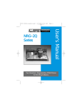
The heart of the Network Gateway Series concept is an element called the
“point database” (refer to Figure 1). The point database is entirely userconfigurable, and provides the end-to-end mapping information that allows
primary network requests to be routed to the correct locations on the
secondary network, while at the same time ensuring that the content of the
request will be understood once it gets there. Additionally, the point database
provides the added benefit of “data mirroring”, whereby current copies of point
values (secondary network data objects) are maintained locally within the
gateway itself. This greatly reduces the primary network’s request-to-response
latency time, as requests (read or write) can be entirely serviced locally,
thereby eliminating the time required to execute a secondary network
transaction.
When properly configured, the gateway will become essentially “transparent”
on the networks, and the primary network master can engage in a seamless
dialogue with one or more secondary network devices. This can all be
accomplished without regard to the characteristics (physical layer or protocol)
of the primary or secondary network.
Primary
Network
Point
Database
Load / Save
Point Files
Figure 1: The Network Gateway Series Concept
6
Secondary
Network(s)
2. Mechanical Diagrams
2.1 Enclosure
Figure 2: Enclosure Dimensions (units are inches)
7
2.2 Mounting Clip
Figure 3: Mounting Clip Dimensions (units are inches)
8
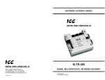
2.3 External Interface
Configuration
Switches
Primary
RS-485
AUX
Power
Figure 4: Bottom View
RS-485
Tx LED
MMI port
Channel
Access
LEDs
RS-485
Rx LED
Secondary
RS-485
ASD #1
Figure 5: Front View
9
ASD Link
LEDs
ASD #2
3. Feature Summary
Primary Network
Half-duplex RS-485 (A / B / Signal Ground / Shield)
Secondary Network
The XLTR-100 has two independent secondary networks, depending on the
application:
•
•
Toshiba ASD common serial: The XLTR-100 provides support for
simultaneous connection of two Toshiba 7-series, 9-series, 11-series
or VF-nC1 ASDs via the drives’ common serial (aka logic level)
communication ports. ASD connections use the same standard RJ45
style 8-conductor UTP patch cables: any standard CAT5 Ethernet
cable (found in most electronics stores) 5 meters or less in length can
be used to connect the XLTR-100 to the drives.
RS-485: Same properties as primary network
Power Supply
When connected to Toshiba ASDs via the ASD 1 / ASD 2 ports, can be either
powered directly from the attached ASDs, or from the auxiliary “POWER” input
jack. All other connections (RS-485 -to- RS-485) require the use of the
auxiliary “POWER” input.
Supported Protocols
•
Primary Network (RS-485)
o Modbus RTU
o Metasys N2
•
Secondary Network
o Toshiba ASD (common serial)
o Modbus RTU (RS-485)
o Sullair Supervisor (RS-485)
o Mitsubishi ASD (RS-485)
New network drivers are continuously being added, and can be downloaded for
free from our web site.
Text-Based Console Configuration
The unit is configured via a text-based console interface, available over RS232
by using the included MMI cable and a standard PC terminal program such as
Microsoft Windows HyperTerminal®.
Point File-Based Configuration
Up to 3 point files (primary / secondary network mapping definition files) can be
stored in the unit’s internal battery-backed file system. Point files can also be
uploaded from / downloaded to a PC, which provides the capability for PCbased file backup and easy configuration copying to multiple units. Sample
10
point files and related documentation can also be downloaded from our web
site, uploaded to a unit, and custom-modified to suit a specific application.
Drive AutoScan Algorithm
Toshiba ASD common serial port connections are automatically established
and continuously monitored (when points are defined for that drive). No drive
configuration needs to be performed to connect the XLTR-100 to the drives.
Just plug it in – it’s that simple.
Network Timeout Action
A configurable network timeout function can be programmed that allows each
internally-defined point to have its own unique “fail-safe” condition in the event
of a primary network interruption.
Indicators
2 green LEDs exist on each of the Toshiba ASD ports and on the MMI port
connector. Refer to section 9 for more detailed information about the LED
indicators and their meanings.
MMI Port Connector
RS232-level. Use the DB9-to-RJ45 MMI cable supplied with the XLTR-100 kit
to interface with the unit for either console-based configuration, point file
upload/download, or flash firmware downloading.
Field-Upgradeable
As new firmware becomes available, the XLTR-100 unit can be upgraded in
the field by the end-user. Refer to section 15 for more information.
Versatile 3-Way DIN-Rail Mounting System
The unit’s enclosure is provided with a mounting clip attached to the rear of the
unit. This clip allows the unit to be mounted 3 different ways:
•
For DIN rail mounting, snap the mounting clip onto a standard DIN
rail, and then snap the unit enclosure onto the clip’s retaining tabs.
This allows easy removal or repositioning of the unit on the DIN rail
during wiring.
•
For panel mounting, the mounting clip can be bolted directly to a flat
panel via the two bolt holes at the top and bottom of the clip. Refer to
section 2.2 for mounting clip mechanical details. Once the mounting
clip is securely attached to the panel, the unit enclosure can be
snapped onto the clip’s retaining tabs.
•
For fixed DIN rail mounting, a combination of the above two
techniques can be employed. First, snap the mounting clip onto a
DIN rail and position it in its desired location. Then, the mounting clip
can be bolted to the DIN rail support panel, securing it in place.
Lastly, the unit can be snapped onto the fixed mounting clip.
11
In all cases, the unit can be easily unsnapped from the mounting clip to
temporarily provide easier access to the configuration switches or network
connector.
12
4. Installing the Interface
The installation procedure of the XLTR-100 will vary slightly depending on the
chosen secondary network.
4.1 RS-485 Secondary Network
Note that in order to power the unit when using the secondary RS-485 network,
you must also purchase the optional 120VAC/9VDC power supply (ICC part
number 10456).
1.
Attach the mounting clip and unit enclosure in your desired manner (refer
to page 11 for more information).
2.
Connect the primary network to the “Primary RS-485” pluggable terminal
block. Refer to section 5 for detailed connection information. Ensure that
the terminal block is fully seated into the terminal block header, and route
the network cable such that it is located well away from any electrical
noise sources, such as ASD input power or motor wiring. Also take care
to route the cable away from any sharp edges or positions where it may be
pinched.
3.
Repeat step 2 above to connect the secondary network to the “Secondary
RS-485” terminal block.
4.
Take a moment to verify that the gateway and all network cables have
sufficient clearance from electrical noise sources such as drives, motors,
or power-carrying electrical wiring.
5.
Connect the power supply to the gateway’s “Power” jack.
13
4.2 Toshiba ASD (Common Serial) Secondary Network
The gateway connects to each drive via the drive’s common serial (logic level)
communication port, typically located on either the main drive control board
(G7, S11), on the front of the drive enclosure under a small snap-on cover (A7,
S9), on the right-hand side of the drive enclosure under a small snap-on cover
(S7), or on the bottom side of the drive enclosure (VF-nC1). Although in
general no drive parameters need to be configured in order to use the
gateway, it is advantageous to check that the drive’s common serial
communication data rate is set to its maximum speed. Because the gateway
will communicate to each drive only at the drive’s configured data rate, this will
provide the fastest response time for drive-to-network data transfers. For
information on checking the drive’s common serial communication data rate,
refer to the appropriate manual supplied with your drive.
Note that the common serial communication parameters of each drive are
handled independently by the gateway, which means that different drive
families may be connected to different channels of the unit in any combination,
and that the drives connected to each channel may simultaneously
communicate to the unit at completely different baud rates, parity settings, etc.
Drives can be connected to the gateway on any ASD channel in any order or
combination. When more than one drive is connected to the unit, or if the
optional auxiliary power supply is used, the gateway will draw its control power
from the source with the highest power supply voltage.
Installation of the gateway should only be performed by a qualified technician
familiar with the maintenance and operation of the connected drives. To install
the gateway, complete the steps outlined in the following sections related to
your specific drive.
4.2.1 Installation for G7 ASDs
1.
2.
3.
CAUTION! Verify that all input power sources to the drives to
be connected have been turned OFF and are locked and tagged out.
DANGER!
Wait at least 5 minutes for the drive’s
electrolytic capacitors to discharge before proceeding to the next step. Do
not touch any internal parts with power applied to the drive, or for at
least 5 minutes after power to the drive has been removed. A hazard
exists temporarily for electrical shock even if the source power has
been removed. Verify that the CHARGE LED has gone out before
continuing the installation process.
Attach the mounting clip and gateway enclosure in your desired manner
(refer to page 11 for more information).
14
4.
Remove the drive’s front cover / open the drive’s cabinet door (refer to the
appropriate drive manual for instructions how to do this).
5.
The drive’s LCD panel (also called the “Electronic Operator Interface” or
“EOI”) can communicate with the drive via either the RS485/RS232
channel (CNU1/CNU1A) or the common serial channel (CNU2/CNU2A).
Because the gateway uses the common serial channel, the LCD panel
must be configured to use the RS485/RS232 channel. If the drive to be
connected is currently using CNU2 (on the drive control board) and
CNU2A (on the LCD panel), then this connection must first be switched
over to CNU1 (on the drive control board) and CNU1A (on the LCD panel).
Refer to Toshiba’s documentation for any precautions or notices regarding
this connection change. If the LCD panel is already connected via the
RS485/RS232 channel, then no change is required.
6.
Configure the drive’s LCD panel to communicate via the RS485/RS232
channel by setting parameter ”Communication Setting
Parameters...Communication Settings...Select LCD Port
Connection” to “RS485/232 serial”.
7.
Connect the drive’s common serial communication port (CNU2) to one of
the ASD channels of the gateway with the communication cable
(communication cable is not included with the gateway kit). When
choosing cables for this connection, standard 24 AWG category 5 (CAT5)
unshielded twisted-pair (UTP) 8-conductor cables found in Ethernet
networks in most office environments can be used. The maximum
allowable length for these cables is 5 meters. Although there are many
varieties and styles of CAT5 UTP cables available, ICC strongly
recommends using only high-quality cables from reputable manufacturers
to guarantee optimal noise immunity and cable longevity. Ensure that
each end of the cable is fully seated into the modular connectors, and
route the cable such that it is located well away from any drive input power
or motor wiring. Also take care to route the cable away from any sharp
edges or positions where it may be pinched.
8.
Reinstall the drive’s front cover / close the drive’s cabinet door.
9.
Repeat steps 1-8 to connect other drive(s) as needed.
10. Connect the primary network to the “Primary RS-485” pluggable terminal
block. Refer to section 5 for detailed connection information. Ensure that
the terminal block is fully seated into the terminal block header, and route
the network cable such that it is located well away from any drive input
power or motor wiring. Also take care to route the cable away from any
sharp edges or positions where it may be pinched.
11. If an auxiliary power supply is going to be used, connect it to the
gateway’s “Power” jack.
12. Take a moment to verify that the gateway and all primary and secondary
network cables have sufficient clearance from drives, motors, or powercarrying electrical wiring.
13. Turn the power sources to all connected drives ON, and verify that the
drives function properly. If the drives do not appear to power up, or do not
15
function properly, immediately turn power OFF. Repeat steps 1 and 2 to
remove all power from the drives. Then, verify all connections. Contact
ICC or your local Toshiba representative for assistance if the problem
persists.
4.2.2 Installation for S7, S9, S11, A7 and VF-nC1 ASDs
1.
2.
CAUTION! Verify that all input power sources to the drives to
be connected have been turned OFF and are locked and tagged out.
DANGER!
Wait at least 5 minutes for the drive’s
electrolytic capacitors to discharge before proceeding to the next step. Do
not touch any internal parts with power applied to the drive, or for at
least 5 minutes after power to the drive has been removed. A hazard
exists temporarily for electrical shock even if the source power has
been removed. Verify that the CHARGE LED has gone out before
continuing the installation process.
3.
Attach the mounting clip and gateway enclosure in your desired manner
(refer to page 11 for more information).
4.
Remove the drive’s common serial communication port cover if it has one
(refer to the appropriate drive manual for instructions how to do this). Do
not discard this cover, as it should be reinstalled to minimize
contamination of the port’s electrical contacts if the gateway is ever
disconnected from the drive.
5.
Connect the drive’s common serial communication port to one of the ASD
channels of the gateway with the communication cable (communication
cable is not included with the gateway kit). When choosing cables for this
connection, standard 24 AWG category 5 (CAT5) unshielded twisted-pair
(UTP) 8-conductor cables found in Ethernet networks in most office
environments can be used. The maximum allowable length for these
cables is 5 meters. Although there are many varieties and styles of CAT5
UTP cables available, ICC strongly recommends using only high-quality
cables from reputable manufacturers to guarantee optimal noise immunity
and cable longevity. Ensure that each end of the cable is fully seated into
the modular connectors, and route the cable such that it is located well
away from any drive input power or motor wiring. Also take care to route
the cable away from any sharp edges or positions where it may be
pinched.
6.
Repeat steps 1, 2, 4 and 5 to connect other drive(s) as needed.
7.
Connect the primary network to the “Primary RS-485” pluggable terminal
block. Refer to section 5 for detailed connection information. Ensure that
the terminal block is fully seated into the terminal block header, and route
the network cable such that it is located well away from any drive input
16
power or motor wiring. Also take care to route the cable away from any
sharp edges or positions where it may be pinched.
8.
If an auxiliary power supply is going to be used, connect it to the
gateway’s “Power” jack.
9.
Take a moment to verify that the gateway and all primary and secondary
network cables have sufficient clearance from drives, motors, or powercarrying electrical wiring.
10. Turn the power sources to all connected drives ON, and verify that the
drives function properly. If the drives do not appear to power up, or do not
function properly, immediately turn power OFF. Repeat steps 1 and 2 to
remove all power from the drives. Then, verify all connections. Contact
ICC or your local Toshiba representative for assistance if the problem
persists.
17
5. RS-485 Electrical Interface
In order to ensure appropriate network conditions (signal voltage levels, etc.),
some knowledge of the gateway’s RS-485 network interface circuitry is
required. Refer to Figure 6 for a simplified network schematic of both the
primary and secondary RS-485 interface circuitry. Note that the “Shield”
terminal has no internal connection: its purpose is simply to provide a cable
shield chaining location between devices. The shield is then typically
connected to ground at one location only.
Figure 6: RS-485 Interface Circuitry Schematic
Figure 7 details the specific network connections to the RS-485 terminal block.
This connection scheme applies equally to the primary as well as secondary
networks.
A
B
Signal Ground
Shield
Figure 7: RS-485 Terminal Block Connections
18
6. Environmental Specifications
Item
Specification
Operating Environment
Indoors, less than 1000m above sea level, do not
expose to direct sunlight or corrosive / explosive
gasses
Operating Temperature
-10 ∼ +50°C (+14 ∼ +122°F)
Storage Temperature
-40 ∼ +85°C (-40 ∼ +185°F)
Relative Humidity
20% ∼ 90% (without condensation)
Vibration
5.9m/s {0.6G} or less (10 ∼ 55Hz)
Grounding
Cooling Method
2
Non-isolated, referenced to power source ground
Self-cooled
19
7. Maintenance and Inspection
Preventive maintenance and inspection is required to maintain the gateway in
its optimal condition, and to ensure a long operational lifetime. Depending on
usage and operating conditions, perform a periodic inspection once every
three to six months. Before starting inspections, disconnect all power sources
(with Toshiba ASD connections, turn off all power supplies to connected drives
and wait at least five minutes after each drive’s “CHARGE” lamp has gone
out.)
Inspection Points
•
Check that the dust covers for all unused RJ45 ports are seated firmly in
their connectors.
•
Check that the network cable(s) are properly terminated in the terminal
block(s), and ensure that pluggable terminal blocks are fully seated in their
headers. Reseat if necessary.
•
Check that there are no defects in any attached wire terminal crimp points.
Visually check that the crimp points are not scarred by overheating.
•
Visually check all wiring and cables for damage. Replace as necessary.
•
Clean off any accumulated dust and dirt.
•
If use of the gateway is discontinued for extended periods of time, apply
power at least once every two years and confirm that the unit still functions
properly.
•
Do not perform hi-pot tests on the gateway, as they may damage the unit.
Please pay close attention to all periodic inspection points and maintain a good
operating environment.
20
8. Storage and Warranty
8.1 Storage
Observe the following points when the gateway is not used immediately after
purchase or when it is not used for an extended period of time.
•
Avoid storing the unit in places that are hot or humid, or that contain large
quantities of dust or metallic dust. Store the unit in a well-ventilated
location.
•
When not using the unit for an extended period of time, apply power at
least once every two years and confirm that it still functions properly.
8.2 Warranty
The gateway is covered under warranty by ICC, Inc. for a period of 12 months
from the date of installation, but not to exceed 18 months from the date of
shipment from the factory. For further warranty or service information, please
contact Industrial Control Communications, Inc. or your local distributor.
21
9. LED Indicators
The gateway contains several different LED indicators, each of which conveys
important information about the status of the unit and connected networks.
These LEDs and their functions are summarized here.
9.1 Toshiba ASD Port Indicators
Each Toshiba ASD port RJ45 connector contains two integrated green LEDs.
Figure 8 indicates the functions of these LEDs.
Network Access
Drive Link
Blinks in 0.1s-long bursts
when drive is accessed by
primary network master
Solid green when a logical
connection exists with the
attached drive
Figure 8: Drive Connector Indicators
The Network Access indicator is useful for confirming that a specific drive
channel is being accessed correctly by the primary network, while the Drive
Link indicator provides an easy method of determining that the XLTR-100 and
drive are successfully exchanging data, independent of primary network
activity (Note: Drive Link LED will only represent “last access” status if no child
points are defined for that channel).
22
9.2 MMI Port Indicators
The MMI port RJ45 connector also contains two integrated green LEDs.
Figure 9 indicates the functions of these LEDs.
RS-485 Transmit Indicator
Blinks in 0.1s-long bursts when
secondary RS-485 network
requests are being transmitted
by the gateway
RS-485 Receive Indicator
Blinks in 0.1s-long bursts when
secondary RS-485 network
responses are being received
by the gateway
Figure 9: MMI Port Indicators
10. Configuration Switches
There are four configuration switches located on the bottom side of the
gateway. Currently, switches #1 - #3 are reserved, and switch #4 is used
during flash firmware reprogramming of the gateway (refer to section 15).
11. Internal Battery
The XLTR-100 gateway has an internal coin-cell type battery that is used to
backup the file system when the gateway is unpowered. This battery is
designed to last the lifetime of the product under normal use. However, if the
gateway is left unpowered for several years, the battery may become
exhausted. For this reason, always be certain to download any customized
point files to a PC so that they will be available for uploading again if the
battery fails and requires replacement.
If the battery becomes discharged, contact ICC for assistance in obtaining a
replacement. Alternatively, it can be replaced by the user by removing all
power sources from the gateway, opening the case, carefully popping out the
discharged battery and replacing it with a Panasonic BR2330 or equivalent
component.
23
12. Point Configuration
As mentioned in section 1, the Network Gateway Series concept revolves
around a central “point database”, containing various individual points. A
“point” is simply an object that defines some sort of primary -to- secondary
network mapping information.
There are two different types of points:
•
•
Parent points
Child points
The relationship between these two point types is as suggested by their
names: parent points (from hereon referred to simply as “parents”) define the
upper-most level of mapping information, and child points (hereon referred to
individually as “child” or collectively as “children”) exist as sub-elements of
parent points, inheriting the parent’s attributes while simultaneously adding
additional mapping information. Parents can have any number of children
assigned to them, limited only by the maximum number of points available
(100 total). In certain instances (such as with a Modbus RTU primary
protocol), it is also possible to have parents that do not have any children
assigned to them. Although the details may vary among different Network
Gateway Series devices, the conceptual relationship for the XLTR-100 is
detailed in Figure 10.
Parent #1
Parent #2
…
Parent #n
Child #1
Child #1
…
Child #2
Child #x
Figure 10: Parent / Child Relationship
24
12.1 Parents
Parents map a primary network address (device) to a secondary network
address (device). This can perhaps best be demonstrated by use of an
example. Say, for instance, that a Metasys N2 Network Control Unit (NCU)
would like to gain access to four Modbus RTU devices. The Modbus devices
have been pre-assigned the addresses 5, 7, 9 and 11. This system is
represented in Figure 11.
N2
NCU
Primary
Network
Gateway
Secondary
Network
Address
5
Address
7
Address
9
Address
11
Modbus
Devices
Figure 11: Example System
In order to allow the NCU to access the Modbus devices, we must create a
parent point for each Modbus device (four total). The secondary addresses of
the parent points must of course be the respective pre-assigned Modbus
addresses (5, 7, 9 and 11), but the parents provide flexibility in assigning the
primary network addresses to be any valid addresses supported by the
network. Let’s say that we would like the NCU to be able to access the four
devices with Modbus network addresses 5, 7, 9 and 11 at Metasys network
addresses 1, 2, 3, and 4, respectively.
Metasys Address
1
2
3
4
Maps To
……………..
……………..
……………..
……………..
25
Modbus Address
5
7
9
11
Therefore, we would need to create our parent points as indicated in Figure 12
(this manual will use the graphical convention of a large, bolded circle with a
line down the middle to represent a parent. The number on the left of the line
will indicate the primary network address, and the number on the right will
indicate the corresponding secondary network address.)
1
5
2
7
3
9
4
11
Figure 12: Parent Assignments for Example System
Note that with these parent assignments, the gateway will now respond to the
NCU on behalf of the four Modbus devices, and it will do so at Metasys
addresses 1, 2, 3 and 4. From this simple example, some observations can be
made:
•
The gateway will consume as much of the primary network address space
as there are parents assigned within it. In this example, the gateway has
4 parents and therefore takes up 4 Metasys addresses. No other devices
(gateways or otherwise) can be assigned primary network addresses that
have already been assigned to the primary side of parents in a gateway.
•
Primary and secondary network parent addresses must be unique. The
gateway will not allow the same parent address to be used more than
once (e.g. you cannot create a parent mapping address 1 to address 5,
and then attempt to create another parent mapping address 1 to address
7).
•
If the Toshiba common serial secondary network physical layer is
selected, then “ASD 1” and “ASD 2” are the only options available for
secondary network addresses. Any addressing entered via the drive’s
panel (“inverter number” parameter, for example) has no relevance to how
that drive is accessed by the gateway.
•
Based on the two previous points, it can be seen that applications using
the Toshiba common serial secondary network physical layer can have at
most two existing parents (some address mapping to “ASD 1”, and some
other address mapping to “ASD 2”).
•
Secondary network device address assignment is relevant only from a
logical or network organizational standpoint. Because the primary network
master never “sees” the true secondary network address assigned to a
device, the secondary network address assignment can be determined by
any user-defined criteria (physical unit position on the floors of a building,
for example), while allowing the primary network address assignment to
be chosen using a different criteria (grouping according to device
application or function, for example).
26
Now that we thoroughly understand the role of parents in the gateway
configuration, let’s move on to the (only slightly more diverse) topic of children.
27
12.2 Children
While parents provide an address-to-address mapping function, children
provide a lower-level object-to-object mapping function. The definition of what
constitutes an object can vary depending on the protocols and devices
involved. For example, an object on the Metasys network can be a Binary
Output (BO), Binary Input (BI), Analog Output (AO) or Analog Input (AI). On
the other hand, an object on a Modbus network is simply a Modbus holding
register, and on a Toshiba network is a drive parameter (configuration
parameters, control parameters and status parameters are all handled the
same by the gateway).
Therefore, a child could map an AO to a register when the primary network is
Metasys N2 and the secondary network is Modbus, or it could map a register
to a drive parameter when the primary network is Modbus and the secondary
network is Toshiba protocol. The child is therefore responsible for migrating a
specific piece of data from a device on one network to a device on another
network. The specific object indices (register number, BI number etc.) are
completely user-configurable within the child point configuration.
The specific configurable items associated with a child depend on primary
network and the type of child. While a child on a Modbus-to-Toshiba network
may require only two pieces of information (Modbus register and
corresponding drive parameter), a child on a Metasys-to-Toshiba network will
require more information (AI multiplier value, BO on/off write data etc.) These
variations will be discussed later during the individual network issues section.
At this point, one may ask “how do I know where the individual objects reside
on the different networks?” The answer to that question lies in each child’s
parent. Children are always “owned” by a parent: the parents determine the
address-to-address mapping, while the children determine the object-to-object
mapping within the parents’ address-to-address mapping space. Parents can
have as many children assigned to them as required to access all the
necessary objects on the secondary network devices (up to the maximum
number of points available, which is 100).
As a continuation of the Metasys-to-Modbus network described in the previous
section, let’s assume that the data shown in Table 1 is to be accessed on each
of the Modbus devices, and that the data’s characteristics are as indicated.
From this table we notice that in total 12 children must be created. Let’s begin
by creating our first child, which will map to Modbus register 10 (“frequency
command”) on Modbus address 5. Because Modbus address 5 is mapped via
a parent to Metasys N2 address 1 (refer to Figure 12), this child will be created
under this parent. From the Metasys NCU’s perspective, the frequency
command is an analog output (AO) object, and it will have a multiplier of 0.01
(writing a Metasys value of 10.50Hz, for example, will therefore result in write
data on the Modbus secondary network of 105010 (0x041A)).
28
Table 1: Example Secondary-Network Data
Modbus Address
5
“
“
“
7
“
9
“
“
11
“
“
Modbus Register
10
15
120
125
2
4
8
9
10
8
9
10
Note
Frequency command (1=0.01Hz)
Operating frequency (1=0.01Hz)
Run/Stop command (run=0x0080)
Run/Stop status (running=0x0080)
Temperature sensor (1=0.1C)
Digital output (ON=0x0001)
Voltage monitor #1 (1=1v)
Voltage monitor #2 (1=1v)
Voltage monitor #3 (1=1v)
Voltage monitor #1 (1=1v)
Voltage monitor #2 (1=1v)
Voltage monitor #3 (1=1v)
Therefore, we would need to create this child as indicated in Figure 13. This
manual will use the graphical convention of a smaller, unbolded circle with a
line down the middle to represent a child. The numbers or letters on the left of
the line will indicate the primary network characteristics (object type, index,
multiplier etc.) and the number on the right will indicate the corresponding
secondary network object index (Modbus register number, for example). The
specifics of these elements will be discussed later in this manual.
AO1
0.01
10
Figure 13: Child Point
In a similar manner, the remaining children can be created under each
respective parent, resulting in the final network diagram as shown in Figure 14.
While the mapping function provided by children may be obvious, there is
another less-apparent service provided by children. This service is termed
“data mirroring”, whereby current copies of point values (secondary network
object data) are maintained locally within the gateway itself. This greatly
reduces the primary network’s request-to-response latency time, as requests
(read or write) can be entirely serviced locally, thereby eliminating the time
required to execute a secondary network transaction. As will be later
discussed in the network-specific sections of this manual, primary networks
with strict response-time requirements (such as Metasys N2) must use data
mirroring (and therefore must have all accessible data objects explicitly
declared as children) in order to ensure that response time specifications are
met. Primary networks without such time requirements (such as Modbus RTU)
may still use data mirroring to optimize network bandwidth, but are not required
to do so.
29
1
5
AO1
0.01
10
AI1
0.01
15
BO1
OFF=0
ON=0x0080
BI1
Bit 7
2
AI1
0.1
BO1
OFF=0
ON=1
7
3
9
4
11
2
AI1
1
8
AI1
1
8
4
AI2
1
9
AI2
1
9
AI3
1
10
AI3
1
10
120
125
Figure 14: Completed Example Configuration
12.3 Network Timeout Settings
The gateway can be configured to perform a specific set of actions when
primary network communications are lost. This allows each internally-defined
child point to have its own unique “fail-safe” condition in the event of a primary
network interruption. There are three separate elements that define the
network timeout behavior:
•
•
•
The network timeout time (refer to section 13.5.1.5)
A child point’s “Timeout Enable” setting (refer to section 13.5.1.1.3)
A child point’s “Timeout Value” setting (refer to section 13.5.1.1.3)
The timeout time is adjustable in 1s increments from 0 to 500s. The default
timeout time is 0, which disables network timeout handling. When nonzero,
timeout processing does not begin until after a valid network packet has been
received by the unit.
30
When the timeout time is nonzero and a communication interruption is
detected, the timeout enable selections for all configured child points are
inspected. Those points that are found to have their timeout enable selections
set to “enabled” will then have their configured timeout values automatically
written to their corresponding secondary network objects. This mechanism
provides for a flexible set of device failsafe conditions to be established on a
point-by-point basis.
12.4 General Configuration Procedure
Now that we have had a brief tutorial on parents and children, we can proceed
on to how these elements fit into the overall configuration procedure. The
general configuration procedure steps can be summarized as follows.
1.
2.
3.
4.
5.
6.
7.
Enter the console (this stops all network communication tasks)
Define a new point setup by selecting the primary and secondary
protocols
Modify network characteristics if necessary
Create parent points
Create child points under parents
Save the newly-created point database to the gateway’s file system,
and download a copy to your PC for backup purposes
Exit the console (resets the gateway)
Of course, it is possible to simplify or even eliminate some of these steps by
starting your configuration from a pre-existing point database file (either
downloaded from the internet or previously-created by the user), and then
simply modifying those elements necessary to match your application.
31
13. Console Access
As mentioned in section 1, the gateway’s functionality is entirely controlled by a
“point database” that is user-modifiable. The method of accessing this
database is via a text-based console interface over an RS232 connection to a
computer’s serial (COM) port. This connection is performed by using the
included DB9-RJ45 cable to connect the gateway’s MMI port to the computer’s
serial port.
13.1 Requirements
All that is needed is a computer with a standard serial (COM) port, some sort
of communications software (such as HyperTerminal, included with Microsoft
Windows operating systems), and the included MMI cable (ICC part number
#10425). Any communications software and PC will work, provided they
support ASCII communications at 38.4kbaud.
13.2 Connection
The gateway ships from the factory with a dust cover installed in the MMI port.
To minimize contamination of the port’s electrical contacts, keep this dust
cover in place whenever the MMI port is not in use.
Connect the RJ45 end of the MMI cable to the MMI port, and connect the other
end to the computer’s serial port.
13.3 Application Configuration
As previously mentioned, any PC communication software and PC serial port
can be used. The software configuration example given here will be for
Windows HyperTerminal communicating via COM1.
Figure 15 shows the “Connect To” tab of the properties window for COM1.
Figure 16 shows the window that appears when “Configure” is selected in the
“Connect To” tab. Figure 17 shows the “Settings” tab of the properties window.
Most of these settings are their default values: usually the only change needed
is the “Bits per second” setting shown in Figure 16.
32
Figure 15: HyperTerminal Properties…Connect To
Figure 16: HyperTerminal Properties…Connect To…Configure
33
Figure 17: HyperTerminal Properties…Settings
34
13.4 Invocation
The console provides standard access and editing methods for the various
configuration items (points and their associated attributes). It is important to
note that unless otherwise indicated, any modifications made to the point
database will become effective immediately. However, these changes will only
be permanently retained when the current database is saved to a file location:
if a change is made to the database and then the gateway is reset without
saving those changes, then the active file will be restored upon initialization,
overwriting the unsaved changes.
To enter the console, simply type “menu” and press the Enter key. You will
then be notified that all communication tasks will be terminated for the duration
of the editing (refer to Figure 18). It is important to ensure that all connected
devices are in a safe state such that loss of communications will not pose a
danger to equipment or personnel. Exiting the console will reset the gateway
and restart network communications using the currently-active database file.
At most console prompt locations, typing “x” will return you to the previous
menu, and typing “menu” will return you to the main menu. Also note that
console commands are not case-sensitive.
Figure 18: Starting the Console
35
13.5 Main Menu
The main menu is shown in Figure 19. All gateway configuration is performed
by “drilling down” into progressively lower-level menus.
Figure 19: Console Main Menu
All navigation and data entry commands are input by simply entering the menu
selection number to the right of the “>” symbol along with any required data
fields at the console prompt. In Figure 19, for example, entering the menu
selection number “1” (without the quotation marks) will bring up the View/Edit
Points submenu. Throughout this manual, example console entry strings will
be provided enclosed in quotation marks to delineate them from the
description text: whenever actually entering the console strings, however, do
not include the quotation marks.
When additional data fields are required with a data entry command, they will
be indicated by square brackets (“[…]”) after the menu selection number. All
data entry commands and data fields must be separated by spaces. Because
data entry commands and data fields are delineated by spaces, they are
therefore not allowed within data fields (such as name strings). In these
cases, it is usually convenient to use an underscore “_” in place of a space.
For example, attempting to enter a filename as “My test file” would result in an
error, but “My_test_file” would be perfectly acceptable.
36
13.5.1 View/Edit Points
Main menu selection number 1 displays a screen which shows a summary of
the current point configuration (see Figure 20). This screen only displays the
parent point (address mapping) information: in order to access any child point
information, menu selection number 1 “Edit a Parent” must be entered with the
additional argument of the targeted parent point’s primary network address.
The top half of the screen contains the parents table, which lists the primary
and secondary network addresses of each parent. The bottom half of the
screen contains the menu options for editing the parent points and network
characteristics.
Figure 20: View/Edit Points
13.5.1.1 Edit a Parent
Entering “1” with a parent point’s primary network address (such as “1 1”, as
shown at the bottom of Figure 20) at the View/Edit Points submenu will display
and allow editing of the parent’s mapping and child point definition information.
Refer to Figure 21 for an example. Although the number of menu selections in
this submenu will remain consistent, the semantics of the menu titles and
argument names will vary slightly depending on the currently-defined networks.
When editing a parent, the top half of the screen contains the children table,
which lists the child types (relevant only for those networks, such as Metasys
N2, which allow different types of children), the primary network object number
and the secondary network object number. The bottom half of the screen
contains the menu options for editing the child points.
37
Whenever a new parent point is added (refer to section 13.5.1.2), no children
are assigned to that parent. One must therefore navigate to the Edit a Parent
submenu in order to add to or modify that parent’s child point configuration.
Throughout the console, note that the entry and display radices of the primary
and secondary network data objects depend on the chosen networks. For
example, entering an “ASD param” number of 10 when the Toshiba ASD
secondary network is selected will map a child to ASD parameter 0x0010
(1610). However, entering an “RTU reg num” of 10 when the Modbus network
is selected will map a child to holding register 1010 (0x0A). These radices are
chosen based on the “natural radix” defined for each protocol. For more
information on the natural radices of the available networks, refer to section
14.
Figure 21: Edit a Parent
13.5.1.1.1 Edit Primary Network Address
Menu selection number 1 allows you to change the current parent’s primary
network address. For example, the bottom of Figure 21 shows an example of
changing a parent’s primary network address to 34.
13.5.1.1.2 Edit Secondary Network Address
Menu selection number 2 allows you to change the current parent’s secondary
network address. The entry method is similar to that for the primary network
address described in section 13.5.1.1.1.
38
13.5.1.1.3 Edit a Child
Entering menu selection number 3 with the additional arguments of the child’s
type and primary network object number will display a submenu that allows
editing of various child characteristics. For example, the top of Figure 22
shows an example of editing Metasys N2 binary output (BO) #1.
The child type varies depending on the primary network selected. For
example, with a Modbus RTU primary network, the child type will always be
“REG” (for “register”). If a Metasys N2 primary network is selected, however,
then the child type could be AO, BO, AI or BI.
Figure 22: Edit a Child
Primary Network Object Number: Submenu selection number 1 allows
modification of the primary network object number. An example of changing
the point shown in Figure 22 from BO #1 to BO #8 would be “1 8”.
Secondary Network Object Number: Submenu selection number 2 allows
modification of the secondary network object number. An example of changing
the point shown in Figure 22 from holding register #2 to holding register #123
would be “2 123”.
Other Attributes: The first two selections in the “Edit a Child” menu will
always be as indicated above. The remainder of the selections, however, will
vary depending on the child’s type. Metasys N2 binary output objects, for
example, will allow configuration of the point’s ON value, OFF value, Timeout
Enable and Timeout Value. Refer to Figure 22 for an example of selecting BO
#1’s timeout value to “ON”
39
13.5.1.1.4 Add a New Child
To add a new child to the configuration, enter menu selection number 4 with
the additional arguments of the child’s type, the child’s primary network object
number, and the child’s secondary network object number. For example,
Figure 23 shows an example of adding a new child to map Modbus holding
register 11 to Toshiba ASD parameter FE14. The semantics of the menu
prompt and allowable object ranges vary depending on the currently-active
networks.
The child type varies depending on the primary network selected. For
example, with a Modbus RTU primary network, the child type will always be
“REG” (for “register”). If a Metasys N2 primary network is selected, however,
then the child type could be AO, BO, AI or BI.
Figure 23: Add a New Child
13.5.1.1.5 Delete a Child
To delete a child from the configuration, enter menu selection number 5 with
the additional arguments of the child’s type and primary network object
number. For example, Figure 24 shows an example of deleting a child that
represents Metasys N2 AO #1. The semantics of the menu prompt and
allowable object ranges vary depending on the currently-active networks.
The child type varies depending on the primary network selected. For
example, with a Modbus RTU primary network, the child type will always be
“REG” (for “register”). If a Metasys N2 primary network is selected, however,
then the child type could be AO, BO, AI or BI.
40
Figure 24: Delete a Child
13.5.1.1.6 More Children
The children table displays the mapping information for 5 children at a time. If
more than 5 children are available in the current configuration, menu selection
number 6 will display the next 5 children in the list. When all children have
been displayed, entering menu selection number 6 will roll back around to the
first 5 children again.
13.5.1.2 Add a New Parent
To add a new parent to the configuration, enter menu selection number 2 with
the additional arguments of the parent’s primary and secondary network
addresses. For example, the bottom of Figure 25 shows an example of adding
a new parent to map Metasys N2 address 4 to Modbus RTU address 9. The
semantics of the menu prompt and allowable address ranges vary depending
on the currently-active networks.
Once the new parent has been added to the parent list, its children (if any)
must be added by using the Edit a Parent menu selection (refer to section
13.5.1.1). Note that parent addresses must be unique: if an attempt is made to
enter a primary or secondary network address that has already been defined,
the console will return an error.
41
Figure 25: Add a New Parent
13.5.1.3 Delete a Parent
Entering menu selection number 3 with the additional argument of a parent’s
primary network address will delete that parent and all of its children.
13.5.1.4 More Parents
The parents table displays the mapping information for 4 parents at a time. If
more than 4 parents are available in the current configuration, menu selection
number 4 will display the next 4 parents in the list. When all parents have
been displayed, entering menu selection number 4 will roll back around to the
first 4 parents again.
13.5.1.5 Primary Network Setup
Menu selection number 5 displays a submenu that provides a means to
configure the characteristics of the selected primary network, such as baud
rate and parity. Refer to Figure 26 for an example. Note that not all primary
networks are user-configurable. The specific menu label and subsequent
available submenu options depend on the currently-active primary network.
Along with the network characteristics, this submenu allows for setting the
network timeout time. For more information on the network timeout
configuration, refer to section 12.3.
42
Figure 26: Example Primary Network Setup
13.5.1.6 Secondary Network Setup
Menu selection number 6 displays a submenu that provides a means to
configure the characteristics of the selected secondary network, such as baud
rate and parity. Note that not all secondary networks are user-configurable.
The specific menu label and subsequent available submenu options depend
on the currently-active secondary network.
13.5.2 Save Points
Main menu selection number 2 allows the current gateway configuration to be
saved to one of the three available file locations in the gateway’s file system. It
is important to reiterate that whenever any configuration changes are
performed, they are performed only on the gateway’s working memory, and
that those changes will be lost unless they are saved to the gateway’s file
system prior to exiting the console. The saved file also becomes the new
active file, which means that it will automatically be loaded from the file system
into the gateway’s working memory every time the gateway boots up. The
gateway provides space for three independent files to be stored.
Refer to Figure 27 for an example of saving the current configuration to file
system location #1 with the name “Assy_Line_6”. “Assy_Line_6” will then also
become the active file, and will be the configuration loaded into the gateway’s
working memory at the beginning of the next boot cycle.
43
Figure 27: Saving a Point File
13.5.3 Load Points
Main menu selection number 3 allows the retrieval of a configuration file from
the gateway’s file system into its working memory. The configuration can then
be modified while in the working memory and saved back to the file system if
desired. Loading a file also causes it to become the active file, which means
that it will automatically be loaded from the file system into the gateway’s
working memory every time the gateway subsequently boots up.
Refer to Figure 28 for an example of loading file “N2_to_2ASD”.
“N2_to_2ASD” will then also become the active file, and will be the
configuration loaded into the gateway’s working memory at the beginning of
the next boot cycle.
44
Figure 28: Loading a Point File
13.5.4 New Points
Main menu selection number 4 is used to begin a new configuration from
scratch. When selected, a prompt will be displayed indicating that the current
configuration in the gateway’s working memory will be cleared (refer to Figure
29). The console will then prompt for the primary and secondary networks (as
an example, Modbus RTU is being selected for the primary network protocol in
Figure 29). This action will clear all parent and child points, necessitating the
general configuration process outlined in section 12.4 to add parents and
children, configure network characteristics, save the point file, etc.
Because the point database is constructed uniquely for a specific
primary/secondary network combination, it is necessary to create a new point
setup anytime the primary or secondary network protocol is changed (or
alternatively, one could start with an existing point setup file with the desired
primary and secondary network protocols already selected, and then modify
the point definitions to fit the target application).
After configuration has been completed, always remember to save the new
point setup to the gateway’s file system prior to restarting. Otherwise, the
currently-active file will be restored from the file system upon boot up,
overwriting the newly-created setup.
45
Figure 29: Beginning a New Setup
13.5.5 Xmodem Point File
Main menu selection 5 provides a method to upload and download point files
to/from your PC via the Xmodem protocol. Xmodem is a data transfer protocol
supported by virtually all terminal emulation programs (such as
HyperTerminal).
Whenever a custom point setup is created, it is highly recommended that a
backup copy of the file be downloaded to a PC in case it becomes necessary
to restore it to the gateway’s file system later (such as if the gateway’s internal
backup battery fails and requires replacement). Two different variations of the
Xmodem protocol are supported (CRC and Checksum) for those terminal
emulation programs that only support one or the other. This menu selection is
also useful for copying point files from one gateway to another, or for uploading
pre-configured point files that have been obtained from the ICC website.
Figure 30 shows an example of initiating the download of the file
“Assy_Line_6” from the gateway’s file system to the PC. Once the file to
download has been chosen, the console will indicate that the gateway is now
ready to transmit the file. At this point, you have 30 seconds in which to initiate
the receive function of your terminal emulation program before the gateway will
timeout the transaction and return to the main menu prompt.
In HyperTerminal, the “receive” function can be selected by the
icon in the
toolbar. This will bring up a dialog box (Figure 31) that allows you to select the
46
file destination and the transfer protocol (Xmodem). Lastly, you will be
prompted for a filename which the point file will be saved under (Figure 32).
Figure 30: Downloading a Point File
Figure 31: HyperTerminal "Receive File" Dialog Box
Figure 32: HyperTerminal "Receive Filename” Dialog Box
47
As soon as the filename is entered and “OK” selected, the download transfer
will begin. This will only take several seconds to complete, and at the
conclusion the console will indicate the status of the transfer and return to the
main menu.
Uploading a file from the PC to the gateway is similar in many ways to
downloading. Figure 33 shows an example of initiating a file upload. Once the
console indicates that the gateway is ready to receive the file, you have 30
seconds in which to initiate the send function of your terminal emulation
program before the gateway will timeout the transaction and return to the main
menu prompt.
Figure 33: Uploading a Point File
icon in the
In HyperTerminal, the “send” function can be selected by the
toolbar. This will bring up a dialog box (Figure 34) that allows you to select the
source file and the transfer protocol (Xmodem). Upon entering the information
and selecting “Send”, the upload transfer will begin. This will only take several
seconds to complete, and at the conclusion the console will indicate the status
of the transfer and, if successful, will prompt for a file system location in which
to store the received file. The console does not prompt for a filename, as the
point file is internally watermarked with the name the file was given when it was
originally created and stored in the file system.
48
Figure 34: HyperTerminal "Send File" Dialog Box
13.5.6 XLTR-100 Information
Main menu selection number 6 displays the unit’s application firmware version
information.
13.5.7 Exit & Restart
Type “exit” at any menu prompt to reboot the gateway and startup the
communication tasks. Note that whenever you modify the point database and
are ready to restart the gateway, you must save the database to the file system
prior to restarting or your changes will be lost. The console will automatically
warn you that any unsaved changes will be lost and prompt you for
confirmation every time you “exit”, even if the database had not been modified.
If the database was unchanged, then no saving is required.
49
14. Network-Specific Information
This section will discuss topics that are specific to each of the available
primary and secondary network selections.
14.1 Primary Networks
14.1.1 Modbus RTU
•
The gateway acts as a Modbus RTU slave. Supported Modbus functions
are indicated in Table 2.
Table 2: Supported Modbus Slave Functions
Function Code
1
3
5
6
15
16
Function
Read coils
Read multiple registers
Write coil
Write single register
Force multiple coils
Write multiple registers
•
Broadcast (for functions 5, 6, 15 and 16) is supported.
•
Required Child Point Information:
o Holding register (4X reference)
•
Point diagram nomenclature: as indicated in Figure 35.
Holding Register
10
Figure 35: Modbus Slave Point Diagram Nomenclature
•
Network characteristics selections
o Baud rate: 2400 / 4800 / 9600 / 19200 / 38400 bps
o Parity: odd / even / none (1 stop bit) / none (2 stop bits)
•
Console holding register number entry radix is decimal (e.g. 10 = 1010)
50
•
Children are optional: because the Modbus protocol does not specify any
response time requirements, targeted registers do not need to be
configured as children (which provide data mirroring). If a targeted holding
register is found to not exist as a defined child point for a specific parent,
then the request will be passed on to the secondary network for servicing.
While providing the benefits of requiring very little configuration (only
parent points need to be defined) and allowing access to the full object
address range on secondary network devices, this technique does incur
the penalty of increased latency, as affected requests must be passed on
to the secondary network for processing and subsequent response.
•
Configuration tip: Improved primary network utilization may be obtained by
appropriately grouping disjoint secondary network objects into contiguous
blocks of children (contiguous holding register assignments). In this way,
the “read multiple registers” and “write multiple registers” functions can be
used to perform transfers of larger blocks of registers using fewer Modbus
transactions compared to a situation where the read/write registers were
arranged in an alternating or scattered fashion.
•
Because the transaction is handled locally within the gateway, write data
checking is not available for defined children. For example, if a write to a
register or coil defined by a child point is performed, and the write data is
out-of-range of the corresponding secondary network object, no Modbus
exception will be immediately returned. However, the child point will
always reflect the secondary network status and object value. In other
words, if such an out-of-range write is performed, the unsuccessful
secondary-side write can be observed by reading the current (unchanged)
value of the child point during a subsequent Modbus transaction.
•
The gateway can be configured to perform a specific set of actions for
each point when Modbus communications are lost. Modbus
communications are said to be “lost” when the gateway does not receive
any Modbus packets for a specified period of time, causing a “network
timeout”. Refer to section 12.3 for more information about configuring
network timeout parameters.
Coil Mappings
The gateway provides read/write support for Modbus coils. Accessing coils
does not reference any new physical data: coils are simply indexes into various
bits of Modbus holding registers. What this means is that when a coil is
accessed, that coil is resolved by the gateway into a specific holding register,
and a specific bit within that holding register. The pattern of coil-to-register/bit
relationships can be described as follows:
Coils 1...16 map to holding register #1, bit0...bit15 (bit0=LSB, bit15=MSB)
Coils 17...32 map to holding register #2, bit0...bit15, and so on.
51
Arithmetically, the coil-to-register/bit relationship can be described as follows:
For any given coil, the holding register in which that coil resides can be
determined by:
coil + 15
holding register =
16
…Equation 1
Where the bracket symbols “ ” indicate the “floor” function, which means that
any fractional result (or “remainder”) is to be discarded, with only the integer
value being retained.
Also, for any given coil, the targeted bit in the holding register in which that coil
resides can be determined by:
bit = (coil − 1) % 16
…Equation 2
Where “coil” ∈[1…65535], “bit” ∈[0…15], and “%” is the modulus operator,
which means that any fractional result (or “remainder”) is to be retained, with
the integer value being discarded (i.e. it is the opposite of the “floor” function).
From these equations, it can be seen that the largest holding register number
that can be accessed via this coil-to-register mapping method is 4096 (which
contains coil 65535).
For clarity, let’s use Equation 1 and Equation 2 in a calculation example. Say,
for instance, that we are going to read coil #34. Using Equation 1, we can
determine that coil #34 resides in holding register #3, as 3.0625 = 3 r1 = 3.
Then, using Equation 2, we can determine that the bit within holding register
#3 that coil #34 targets is (34-1)%16 = 1, as 33%16 = mod(3 r1) = 1.
Therefore, reading coil #34 will return the value of holding register #3, bit #1.
Note that this coil-to-register/bit relationship holds true regardless of how (or
even if) holding register #3 is defined. If holding register #3 is defined as a
point in the point database, then this coil access will be entirely internal to the
unit. If holding register #3 is not defined as a point in the point database,
however, then an on-demand secondary-network transaction will take place,
requesting data object number 3 and returning the value of bit #1 of that data
object. Either way, coil #34 will always access holding register #3, bit #1.
52
14.1.2 Metasys N2
•
The gateway acts as a Johnson Controls Metasys N2 slave, and supports
N2 analog input, analog output, binary input and binary output object
types.
•
Analog input (AI) objects are used for monitoring analog status items. AI
objects support low alarm limits, low warning limits, high warning limits,
high alarm limits and differential values. Change of state (COS), alarm
and warning functions can also be enabled. An AI object will accept an
override command, but will not change its actual value or indicate override
active. A “multiplier value” is associated with the object, and is multiplied
to the child’s secondary network data to produce the floating-point AI
value sent to the NCU (AI value = [secondary-side data value] X
multiplier). The AI point diagram nomenclature is as indicated in Figure
36.
NPA (Network Point Address) = 1, 2…
“AI” = NPT (Network Point Type)
AI1
0.01
Multiplier
Figure 36: N2 AI Object Point Diagram Nomenclature
•
Analog output (AO) objects are used for setting and monitoring analog
control and configuration items. An AO value can be modified by issuing
an override command. Issuing a release command will not cause the AO
to automatically return to its pre-override value, nor will the AO
automatically return to its pre-override value after a certain time period of
no communication. A “multiplier value” is associated with the object, and
the floating-point AO value is divided by this multiplier to produce the
secondary network data result (secondary-side data value = [AO value] /
multiplier). The AO point diagram nomenclature is as indicated in Figure
37.
NPA (Network Point Address) = 1, 2…
“AO” = NPT (Network Point Type)
AO1
0.01
Multiplier
Figure 37: N2 AO Object Point Diagram Nomenclature
•
Binary input (BI) objects are used for monitoring discrete (digital) status
items. BI objects support COS, alarm enabling and normal/alarm status
53
indications. A BI object will accept an override command, but will not
change its actual value or indicate override active. A “bit mask” is
associated with the object, and is used to determine the current state of
the BI by inspecting the child’s secondary-network data at the bit location
indicated in the bit mask. If the indicated bit is a “1”, then the BI’s current
state is set to “1”. Else, it is set to “0”. The secondary-network data’s
least-significant bit (LSB) is bit #0, and the most-significant bit (MSB) is bit
#15. The BI point diagram nomenclature is as indicated in Figure 38. In
the example indicated by this figure, BI1’s current state will be “1”
whenever bit #7 of the secondary-network data is “1” (e.g. 0x0080), and
will be “0” at all other times.
NPA (Network Point Address) = 1, 2…
“BI” = NPT (Network Point Type)
BI1
Bit 7
Bit Mask
Figure 38: N2 BI Object Point Diagram Nomenclature
•
Binary output (BO) points are used for setting and monitoring discrete
control and configuration items. A BO value can be modified by issuing an
override command. Issuing a release command will not cause the BO to
automatically return to its pre-override value, nor will the BO return to its
pre-override value after a certain time period of no communication. An
“ON” value and an “OFF” value (both 16-bit numbers) are associated with
the object. When the BO’s current state is set to “1” by the NCU, then the
“ON” value is written to the child’s secondary-network data object, and
when the BO’s current state is set to “0” by the NCU, then the “OFF” value
is written to the child’s secondary-network data object. In this way,
complex or multi-function secondary-network commands can be issued in
response to a simple Metasys BO ON/OFF override command. The BO
point diagram nomenclature is as indicated in Figure 45.
NPA (Network Point Address) = 1, 2…
“BO” = NPT (Network Point Type)
“OFF” Value
“ON” Value
BO1
OFF=0
ON=0x0080
Figure 39: N2 BO Object Point Diagram Nomenclature
•
The Metasys device type for the gateway is VND.
•
Console object number entry radix is decimal (e.g. 10 = 1010)
54
•
Because the Metasys N2 protocol specifies strict response timing
requirements, all accessible data objects must be designated as child
points, thereby making use of data mirroring.
•
Network characteristics selections: not configurable according to the
Metasys N2 specification.
•
Because all transactions are handled locally within the gateway, write data
checking is not available. For example, if a write to an object is
performed, and the write data is out-of-range of the corresponding
secondary network object, no N2 error will be immediately returned.
However, the N2 object will always reflect the secondary network status
and data object value. In other words, if such an out-of-range write is
performed, the unsuccessful secondary-side write will be detected and the
N2 object’s value corrected. If COS is enabled for that object, the
correction will be reported to the NCU upon the next COS poll request.
•
The gateway can be configured to perform a specific set of actions for
each AO or BO point when Metasys communications are lost. Metasys
communications are said to be “lost” when the gateway does not receive
any Metasys packets for a specified period of time, causing a “network
timeout”. Refer to section 12.3 for more information about configuring
network timeout parameters.
55
14.2 Secondary Networks
14.2.1 Modbus RTU
•
The gateway acts as a Modbus RTU master via the secondary RS-485
port. Supported Modbus functions are indicated in Table 3.
Table 3: Supported Modbus Master Functions
Function Code
3
16
Function
Read multiple registers
Write multiple registers
•
The slave response timeout is fixed at 3s.
•
Network characteristics selections
o Baud rate: 2400 / 4800 / 9600 / 19200 / 38400 bps
o Parity: odd / even / none (1 stop bit) / none (2 stop bits)
•
Any defined children will be continuously read by the gateway for data
mirroring. When allowed by the primary network protocol, primary network
requests that target registers not declared as children will generate
secondary network traffic only on-demand.
•
Modbus RTU is not available as the secondary network if it has already
been selected as the primary network.
•
Console holding register number entry radix is decimal (e.g. 10 = 1010)
56
14.2.2 Toshiba Protocol
•
The gateway acts as a Toshiba ASD master via the dedicated common
serial port connections. All Toshiba ASDs that include a common serial
port are supported.
•
Network characteristics selections: no configuration is necessary, as the
gateway automatically adapts to the ASD’s configured characteristics.
•
Any defined children will be continuously read by the gateway for data
mirroring. When allowed by the primary network protocol, primary network
requests that target ASD parameters not declared as children will
generate secondary network traffic only on-demand.
•
All parameter writes use the drive’s RAM / EEPROM data write (“W”)
command. For all writes that target the drive’s EEPROM, be sure to follow
Toshiba’s guidelines regarding the number of times a specific parameter
can be written without risk of EEPROM damage.
•
Console parameter number entry radix is hexadecimal (e.g. 10 = 0x0010
or 1610)
57
14.2.3 Mitsubishi Protocol
•
The gateway acts as a Mitsubishi protocol master via the secondary RS485 port. Adjustable speed drives such as the FR-A500/E500/F500 series
that support the Mitsubishi protocol can be accessed.
•
The gateway can connect to the ASD via either the PU (panel) connector,
or via an optional FR-A5NR computer link board. Because the ASDs
externally present a 4-wire RS-485 network, connecting them to the
gateway requires jumpering the network wires for 2-wire format (i.e.
connecting SDA-RDA and SDB-RDB).
When Using an FR-A5NR Card
Connect as shown in Figure 40.
A
(TB:1)
B
(TB:2)
Signal
Ground
(TB:3)
Figure 40: FR-A5NR Connections
When Using the PU Port
Connecting to the drive’s RJ-45 PU port will likely require building a
custom cable. For simplicity, a standard 8-conductor Ethernet patch cable
can be used as a starting point. There are two standard color schemes for
the wire pairs in such cables as defined by the Electronic Industry
Association / Telecommunications Industry Association (EIA-TIA). These
two standards are called T-568B and T-568A (refer to Figure 41). The
most common color scheme is T-568B, and will therefore be the one used
for this example connection. If starting with a cable wired according to the
T-568A specification, just interchange the colors to achieve the same pin
connections.
Connect as shown in Figure 42.
58
Figure 41: EIA/TIA Wiring Standards
RDA SDA
SDB RDB
A
(TB:1)
B
(TB:2)
Signal
Ground
(TB:3)
Figure 42: PU Port Connections
•
The slave response timeout is fixed at 2s.
•
Network characteristics selections
o Baud rate: 300 / 600 / 1200 / 2400 / 4800 / 9600 / 19200 bps
o Parity: odd / even / none (1 stop bit) / none (2 stop bits)
•
Console parameter number entry radix is decimal (e.g. 10 = 1010)
•
Any numerically-addressed parameter defined by the Mitsubishi protocol
reference manual is directly accessible (base frequency = parameter #3,
59
etc.). However, some ASD data objects do not have parameter numbers
assigned by Mitsubishi. For these data objects, the additional parameter
numbers indicated in Table 4 have been assigned. For further information
on these parameters, please refer to the relevant Mitsubishi
documentation.
Table 4: Additional Mitsubishi Parameter Assignments
Parameter
Number
1000
1001
1002
1003
1004
1005
1006
1007
1008
1009
1010
1011
1014
1015
1016
1017
Item
Second parameter switch-over
Frequency command (RAM)
Frequency command (EEPROM)
Frequency monitor
Output current monitor
Output voltage monitor
Special monitor
Special monitor selection number
Most recent #1 and #2 alarms / alarm clear
Most recent #3 and #4 alarms
Most recent #5 and #6 alarms
Most recent #7 and #8 alarms
Inverter status monitor / operation command
Operation mode acquisition
All parameter clear
Inverter reset
•
Any defined children will be continuously read by the gateway for data
mirroring. When allowed by the primary network protocol, primary network
requests that target parameters not declared as children will generate
secondary network traffic only on-demand.
•
ASD communication characteristics are dictated by parameters 117-124
(PU port) and 331-342 (FR-A5NR interface). Most of these parameters
can be set as desired by the user. However, the following parameters
must be set as indicated to successfully connect to the gateway:
Parameter 119/333 (stop bits/data bits).........Must be set for 8 data bits
Parameter 123/337 (wait time setting) ...........Must be set to 9999
Parameter 124/341 (CR/LF selection) ...........Must be set to 1 (CR only)
60
14.2.4 Sullair Supervisor Protocol
•
The gateway acts as a Sullair Supervisor Protocol network monitor via the
secondary RS-485 port. It can automatically adapt to the Supervisor
network configuration (sequencing or non-sequencing/slave mode).
•
Any numerically-addressed parameter defined by the Supervisor protocol
is directly accessible (machine type = parameter #1, etc.). However,
some Supervisor data objects are not natively numerically-addressed. For
these data objects, the additional parameter numbers indicated in Table 5
have been assigned.
Table 5: Additional Supervisor Parameter Assignments
Item
Note
Source
Run status
104
Mode
105
106
107
108
109
110
111
112
113
114
115
116
117
118
119
120
P1
P2
P3
P4
T1
T2
T3
T4
T5
ID
Analog shutdown
Relay outputs
Digital shutdown
Digital inputs
Run time
Load time
126
Online
127
Faulted
Info status
103
0 = E-stop
1 = remote stop
2 = manual stop
3 = standby
4 = starting
5 = load
6 = unload
7 = trim
8 = full load
0 = auto
1 = continuous
Net / quick status
Capacity
P2
Run hours
0 = offline (not sequencing)
1 = online (sequencing)
0 = not faulted
1 = faulted
61
Net /
quick
status
Parameter
Number
100
101
102
•
Any defined children will be continuously read by the gateway for data
mirroring. Additionally, info status messages will always be sent to
defined parent addresses. Otherwise, when allowed by the primary
network protocol, primary network requests that target Supervisor
parameters not declared as children will generate secondary network
traffic only on-demand.
•
Network characteristics selections: no configuration is possible. The baud
rate is fixed at 9600 baud.
•
The gateway Supervisor interface is primarily a system monitor and
configuration device. As such, the following native Supervisor network
commands are not accessible:
S – Stop
L – Load (modulate)
T – Trim (modulate)
D – Display message
C – Cont run mode
•
U – Unload
F – Full load
E – Emergency stop
A – Auto run mode
Console parameter number entry radix is decimal (e.g. 10 = 1010)
62
15. Firmware Updates
The gateway’s embedded firmware resides in flash memory that can be
updated in the field. Firmware updates may be released for a variety of
reasons, such as custom firmware implementations, firmware improvements
and added functionality as a result of user requests.
ICC is continually striving to enhance the functionality and flexibility of our
products, and we therefore periodically release new embedded firmware to
achieve these goals and meet customer requests. Flash firmware files and all
related documentation (such as updated user manuals) can be downloaded as
complete board support packages (referred to as BSPs) from
http://www.iccdesigns.com. It is suggested that users check this Internet site
prior to installation, and then periodically afterwards to determine if new
support packages have been released and are available to upgrade their units.
15.1 Requirements
Besides the new firmware file, firmware updates require a PC with a Windows
operating system (Windows 95 or newer) and a serial port, the RFU PC
application (refer to section 15.3), and the MMI cable included with the
gateway kit (ICC part number 10425).
Please be sure to read the firmware release notes and updated user’s manual
(included with the BSP) for any important notices, behavior precautions or
configuration requirements prior to updating your firmware. For example,
upgrading to a new firmware version may affect user-defined point files: prior
to starting an update procedure always back up your point files to a PC for
later recovery if necessary.
15.2 Connection
The gateway ships from the factory with a dust cover installed in the MMI port.
To minimize contamination of the port’s electrical contacts, keep this dust
cover in place whenever the MMI port is not in use.
IMPORTANT: Note that the gateway will not be operating its system
control and communication tasks while its internal firmware is being updated.
Therefore, be sure to shut down the system to a known safe state prior to
initiating the firmware update procedure.
Connect the RJ45 end of the MMI cable to the MMI port, and connect the other
end to the computer’s serial port. Move “CONFIG” switch #4 to the “ON”
(down) position: this will place the gateway into the “firmware download” mode.
Whenever “CONFIG” switch #4 is “ON”, the gateway can only download
firmware to its flash memory: all other application functions (such as
communications, console access etc.) will be disabled.
63
15.3 Using the RFU Utility
Support for downloading new application firmware to the gateway is provided
by the free Rabbit Field Utility (RFU), which is a 32-bit application that runs on
Microsoft Windows platforms. The RFU utility can be downloaded from ICC’s
home page at http://www.iccdesigns.com. When downloading a new gateway
application BSP, always confirm that you also have the latest version of RFU,
as new .BIN firmware files contained in BSPs may require functionality found
only in the most recent RFU versions for successful downloading.
The remainder of this section will detail the RFU utility configuration and
firmware download procedures.
15.3.1 Required Files
When first downloaded, the RFU utility files are compressed into one selfextracting .EXE distribution file. Create a folder (such as c:\RFU), place the
distribution file in this folder, and then execute it. This will extract the
compressed files into that same folder. The distribution file is then unneeded
and can be deleted if desired. To run the RFU utility, double-click on the
RFU.EXE file icon.
15.3.2 First-Time Configuration
The first time the RFU utility is run on a computer, several configuration items
need to be confirmed. These configuration items are retained in the
computer’s registry from that point on, so reconfiguration is not required unless
certain parameters (such as which serial port to use on the computer) are
changed.
The two configuration items that need to be confirmed are the communications
and bootstrap loaders path. First, select the “Setup…Communications” menu
item (refer to Figure 43).
Figure 43: RFU Main Screen
64
The Communications Options window shown in Figure 44 then appears.
Confirm that the settings are as shown, with the possible exception of the
“Comm Port” settings, which depends on the COM port you are using. Click
“OK” when complete.
Note: It is possible that certain computers may have difficulty communicating
at a sustained 115kbaud rate, which may result in communication errors during
firmware downloading. If this occurs, try setting the “baud rate” parameter
shown in Figure 44 to a lower value.
Figure 44: Communications Options Window
Next, select the “Setup…File Locations” menu item from the main screen. The
“Choose File Locations” window shown in Figure 45 then appears. Confirm
that the correct paths to the referenced files are entered. Enter the correct
paths if necessary.
65
Figure 45: Choose File Locations Window
15.3.3 Transmitting Firmware Files
When a board support package (BSP) has been downloaded and unzipped,
the flash firmware file will be the one with “.BIN” as its file name extension.
Once the RFU utility has been configured, the flash firmware files can be
downloaded to the gateway by two different methods. The simplest way is to
drag the application firmware .BIN file’s icon and drop it onto the RFU utility’s
main screen. This will automatically initiate the download process.
Alternatively, select the “File…Load Flash Image” menu item (refer to Figure
46).
Figure 46: Load Flash Image Menu Selection
The flash image (.BIN file) selection window will then appear (refer to Figure
47). Browse to the location of the flash image file and select it. Clicking “OK”
will then initiate the download process.
66
Figure 47: Flash File Selection Window
While downloading, the RFU utility will indicate the download status. Once
complete, summary information will be displayed in the bottom status bar (see
Figure 48).
Figure 48: Summary Information
15.4 Wrap-Up
Once downloading is complete, close the RFU utility, move “CONFIG” switch
#4 back to the “OFF” (up) position to exit “firmware download” mode, and cycle
power momentarily to the unit by either disconnecting the auxiliary power
supply and/or powering down all connected drives or momentarily removing all
drive communication cables from the unit.
When the unit powers up again, it will be running the new application firmware.
If the new firmware version release notes indicated that point files might need
to be reloaded, then do so at this point.
When completed with MMI port use, remove the MMI cable and replace the
MMI port dust cover to minimize contamination of the port’s electrical contacts.
67
16. Notes
68
69
70
NETWORK GATEWAY SERIES
ICC
INDUSTRIAL CONTROL COMMUNICATIONS, INC.
ICC
XLTR-100
INDUSTRIAL CONTROL COMMUNICATIONS, INC.
2204 Timberloch Place, Suite 250
The Woodlands, TX USA 77380-1049
Tel: [281] 292-0555 Fax: [281] 292-0564
World Wide Web http://www.iccdesigns.com
Printed in U.S.A
RS-485 MULTIPROTOCOL NETWORK GATEWAY
December 2004
ICC #10484-2.100-000