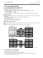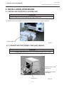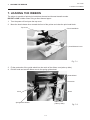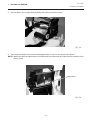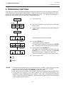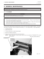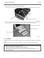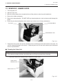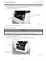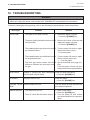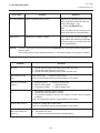
1
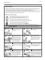
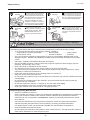
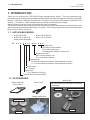
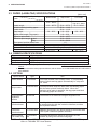
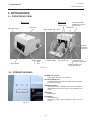
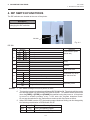
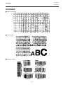
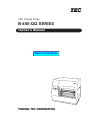
TEC Thermal Printer
B-450-QQ SERIES
Owner’s Manual
Table of Contents
This equipment has been tested and found to comply with the limits for a Class A digital device, pursuant
to Part 15 of the FCC Rules. These limits are designed to provide reasonable protection against harmful
interference when the equipment is operated in a commercial environment. This equipment generates,
uses, and can radiate radio frequency energy and, if not installed and used in accordance with the
instruction manual, may cause harmful interference to radio communications.
Operations of this equipment in a residential area is likely to cause harmful interference in which case
the user will be required to correct the interference at his own expense.
(for USA only)
Changes or modifications not expressly approved by manufacturer for compliance could void the user's
authority to operate the equipment.
"This Class A digital apparatus meets all requirements of the Canadian Interference-Causing Equipment
Regulations."
"Cet appareil numérique de la classe A respecte toutes les exigences du Règlement sur le matériel
brouilleur de Canada."
(for CANADA only)
(for QQ, QQ-PAC only)
Copyright © 1999
by TOSHIBA TEC CORPORATION
All Rights Reserved
570 Ohito, Ohito-cho, Tagata-gun, Shizuoka-ken, JAPAN
EO1-33006
Safety Summary
Safety Summary
Personal safety in handling or maintaining the equipment is extremely important. Warnings and Cautions
necessary for safe handling are included in this manual. All warnings and cautions contained in this
manual should be read and understood before handling or maintaining the equipment.
Do not attempt to effect repairs or modifications to this equipment. If a fault occurs that cannot be rectified
using the procedures described in this manual, turn off the power, unplug the machine, then contact your
authorized TOSHIBA TEC representative for assistance.
Meanings of Each Symbol
This symbol indicates warning items (including cautions).
Specific warning contents are drawn inside the symbol.
(The symbol on the left indicates a general caution.)
This symbol indicates prohibited actions (prohibited items).
Specific prohibited contents are drawn inside or near the symbol.
(The symbol on the left indicates “no disassembling”.)
This symbol indicates actions which must be performed.
Specific instructions are drawn inside or near the symbol.
(The symbol on the left indicates “disconnect the power cord plug from the outlet”.)
WARNING
Any other than the
specified AC voltage
is prohibited.
This indicates that there is the risk of death or serious injury if the
machines are improperly handled contrary to this indication.
Do not use voltages other than the
voltage (AC) specified on the rating
plate, as this may cause fire or
electric shock.
Prohibited
Do not plug in or unplug the power
cord plug with wet hands as this may
cause electric shock.
Prohibited
If the machines share the same
outlet with any other electrical
appliances which consume large
amounts of power, the voltage will
fluctuate widely each time these
appliances operate. Be sure to
provide an exclusive outlet for the
machine as this may cause the
machines to malfunction.
Prohibited
Do not place metal objects or
water-filled containers such as flower
vases, flower pots or mugs, etc. on
top of the machines. If metal objects
or spilled liquid enter the machines,
this may cause fire or electric
shock.
Prohibited
Do not insert or drop metal,
flammable or other foreign objects into
the machines through the ventilation
slits, as this may cause fire or electric
shock.
Prohibited
Do not scratch, damage or modify
the power cords. Also, do not place
heavy objects on, pull on, or excessively bend the cords, as this may
cause fire or electrical shock.
Disconnect
the plug.
If the machines are dropped or their
cabinets damaged, first turn off the
power switches and disconnect the
power cord plugs from the outlet, and
then contact your authorized
TOSHIBA TEC representative for
assistance. Continued use of the
machine in that condition may cause
fire or electric shock.
Disconnect
the plug.
Continued use of the machines in an
abnormal condition such as when the
machines are producing smoke or
strange smells may cause fire or electric shock. In these cases, immediately turn off the power switches and
disconnect the power cord plugs from
the outlet. Then, contact your authorized TOSHIBA TEC representative for
assistance.
(i)
EO1-33006
Safety Summary
Disconnect
the plug.
Connect a
grounding
wire.
If foreign objects (metal fragments,
water, liquids) enter the machines,
first turn off the power switches and
disconnect the power cord plugs from
the outlet, and then contact your
authorized TOSHIBA TEC representative for assistance. Continued
use of the machine in that condition
may cause fire or electric shock.
Disconnect
the plug.
When unplugging the power cords,
be sure to hold and pull on the plug
portion. Pulling on the cord portion
may cut or expose the internal wires
and cause fire or electric shock.
Ensure that the equipment is
properly grounded. Extension cables
should also be grounded. Fire or
electric shock could occur on
improperly grounded equipment.
No disassembling.
Do not remove covers, repair or
modify the machine by yourself. You
may be injured by high voltage, very
hot parts or sharp edges inside the
machine.
indicates that there is the risk of personal Injury or damage to
CAUTION This
objects if the machines are improperly handled contrary to this indication.
Precautions
The following precautions will help to ensure that this machine will continue to function correctly.
• Try to avoid locations that have the following adverse conditions:
* Temperatures out of the specification
* Direct sunlight
* High humidity
* Shared power source
* Excessive vibration
* Dust/Gas
• The cover should be cleaned by wiping with a dry cloth or a cloth slightly dampened with a mild
detergent solution. NEVER USE THINNER OR ANY OTHER VOLATILE SOLVENT on the plastic
covers.
• USE ONLY TOSHIBA TEC SPECIFIED paper and ribbons.
• DO NOT STORE the paper or ribbons where they might be exposed to direct sunlight, high temperatures, high humidity, dust, or gas.
• Ensure the printer is operated on a level surface.
• Any data stored in the memory of the printer could be lost during a printer fault.
• Try to avoid using this equipment on the same power supply as high voltage equipment or equipment likely to cause mains interference.
• Unplug the machine whenever you are working inside it or cleaning it.
• Keep your work environment static free.
• Do not place heavy objects on top of the machines, as these items may become unbalanced and fall
causing injury.
• Do not block the ventilation slits of the machines, as this will cause heat to build up inside the
machines and may cause fire.
• Do not lean against the machine. It may fall on you and could cause injury.
• Care must be taken not to injure yourself with the printer paper cutter.
• Unplug the machine when it is not used for a long period of time.
Request Regarding Maintenance
•
Utilize our maintenance services.
After purchasing the machine, contact your authorized TOSHIBA TEC representative for assistance
once a year to have the inside of the machine cleaned. Otherwise, dust will build up inside the
machines and may cause a fire or a malfunction. Cleaning is particularly effective before humid
rainy seasons.
•
Our preventive maintenance service performs the periodic checks and other work required to
maintain the quality and performance of the machines, preventing accidents beforehand.
For details, please consult your authorized TOSHIBA TEC representative for assistance.
•
Using insecticides and other chemicals
Do not expose the machines to insecticides or other volatile solvents. This will cause the cabinet or
other parts to deteriorate or cause the paint to peel.
(ii)
EO1-33006
TABLE OF CONTENTS
Page
1. INTRODUCTION ................................................................................................ 1- 1
1.1 APPLICABLE MODEL ................................................................................ 1- 1
1.2 ACCESSORIES .......................................................................................... 1- 1
2. SPECIFICATIONS .............................................................................................. 2- 1
2.1 GENERAL SPECIFICATIONS .................................................................... 2- 1
2.2 PRINTING SPECIFICATIONS .................................................................... 2- 1
2.3 PAPER (LABEL/TAG) SPECIFICATIONS .................................................. 2- 2
2.4 RIBBON SPECIFICATIONS ....................................................................... 2- 2
2.5 OPTION ...................................................................................................... 2- 2
3. APPEARANCE ................................................................................................... 3- 1
3.1 FRONT/REAR VIEW ................................................................................... 3- 1
3.2 OPERATION PANEL .................................................................................. 3- 1
4. DIP SWITCH FUNCTIONS ................................................................................. 4- 1
5. SETUP PROCEDURE ........................................................................................ 5- 1
5.1 REQUIREMENTS FOR OPERATION ........................................................ 5- 1
5.2 SETTING UP THE PRINTER ...................................................................... 5- 1
6. INSTALLATION PROCEDURE ......................................................................... 6- 1
6.1 INSTALLING THE SUPPLY HOLDER UNIT .............................................. 6- 1
6.2 CONNECTING THE POWER CORD AND CABLES .................................. 6- 1
7. LOADING THE RIBBON .................................................................................... 7- 1
8. LOADING THE PAPER ...................................................................................... 8- 1
9. THRESHOLD SETTING ..................................................................................... 9- 1
10. CARE/HANDLING OF THE PAPER AND RIBBON ........................................ 10- 1
11. GENERAL MAINTENANCE ............................................................................. 11- 1
11.1 CLEANING ................................................................................................ 11- 1
11.2 COVERS ................................................................................................... 11- 2
11.3 REMOVING JAMMED PAPER ................................................................. 11- 3
12. TROUBLESHOOTING ..................................................................................... 12- 1
APPENDIX ............................................................................................................. 13- 1
INDEX
CAUTION:
1. This manual may not be copied in whole or in part without prior written permission of TOSHIBA
TEC.
2. The contents of this manual may be changed without notification.
3. Please refer to your local Authorized Service representative with regard to any queries you may
have in this manual.
1. INTRODUCTION
EO1-33006
1.1 APPLICABLE MODEL
1. INTRODUCTION
Thank you for choosing the TEC B-450 Series thermal/transfer printer. This new generation high
performance high quality printer is equipped with the latest hardware including the newly developed high
density (11.8 dot/mm, 300 dot/inch) print head. This allows very clear print at a maximum speed of 101.6
mm/sec. (4 inch/sec.). Other standard features include an external paper supply.
Optional features include a strip mechanism and cutter mechanism.
This manual contains general set-up and maintenance information and should be read carefully to help
gain maximum performance and life from your printer. For most queries please refer to this manual and
keep it safe for future reference.
1.1 APPLICABLE MODEL
• B-452-TS10-QQ
• B-452-TS11-QQ-PAC
Model name description
• B-452-TS10-QQ-US
• B-452-TS11-US-PAC
B - 4 5 2 - T S 1 0 - Q Q - P A C
Special Code
US: North America Block
PAC: with a start up kit
No description: without a start up kit
Destination Code
QQ: Canada, Mexico, etc.
US: North America Block
Specification
10: without Centronics interface and expansion memory
11,12: with Centronics interface and expansion memory
Issue mode
S: Batch
Resolution
T: 11.8 dots/mm (300 dpi)
Thermal direct/Thermal transfer
1.2 ACCESSORIES
Start Up Kit
Owner's Manual
(EO1-33006)
Power Cord
The PAC model also includes the following
accessories.
CD-ROM
Parallel Interface Cable
Supply Holder Unit
Supply Holder
Ribbon
Spacer
1-1
EO1-33006
2. SPECIFICATIONS
2.1 GENERAL SPECIFICATIONS
2. SPECIFICATIONS
2.1 GENERAL SPECIFICATIONS
Model
B-452-TS10-QQ
Item
Supply voltage
Power consumption
Operating temperature
Relative humidity
Dimensions
Weight
100 ~ 120V, 60Hz
0.94 A, 47 W maximum (standby: 0.3 A, 18 W maximum)
5˚C ~ 40˚C
25% ~ 85%RH (no condensation)
270 mm (width) x 245 mm (height) x 200 mm (depth), with Supply holder
unit 410 mm (depth)
4.7 kg (without paper and ribbon)
2.2 PRINTING SPECIFICATIONS
Model
B-452-TS10-QQ
Item
Print head
Printing methods
Print speeds
Maximum print width
Dispensing modes
Available bar-code types
Two-dimensional code
Graphics
Fonts
Rotations
Standard interfaces
∗
Thermal print head 11.8 dots per mm (300 dots per inch)
Direct thermal or Thermal transfer
50.8 mm/sec. (2 inch/sec.) for serial barcodes and two-dimensional codes,
101.6 mm/sec. (4 inch/sec.)
105.7 mm (4.16 inches)
Batch (Continuous), Strip (Option) and Cut modes (Option)
(Both cut and strip modes are available only when their respective modules
are fitted.)
JAN8, JAN13, EAN8, EAN8 + 2 digits, EAN8 + 5 digits
EAN13, EAN13 + 2digits, EAN13 + 5 digits
UPC-E, UPC-E + 2 digits, UPC-E + 5 digits
UPC-A, UPC-A + 2 digits, UPC-A + 5 digits
MSI, ITF, NW-7, CODE39, CODE93, CODE128
Industrial 2 to 5, UCC/EAN128, Customer bar code, POSTNET
RM4SCC, KIX code
Data Matrix, PDF417, QR code, Maxi code
All types of graphic files are available when using the windows driver.
However, only BMP and PCX files are available when using the programming commands.
Times Roman (6 sizes), Helvetica (6 sizes), Presentation (1 size),
Letter Gothic (1 size), Prestige Elite (2 sizes), Courier (2 sizes),
OCR (2 types), Writable characters, Outline font (7 type)
Optional Ture Type Fonts (20 type)
0˚, 90˚, 180˚, 270˚
Serial interface (RS-232C)
Optional parallel interface (Centronics)
Optional keyboard interface
Data MatrixTM is a trademark of International Data Matrix, Inc.
PDF417 is a trademark of Symbol Technologies, Inc.
QR code is a trademark of DENSO CORPORATION.
Maxi code is a trademark of United Parcel Service of America, Inc.
2-1
EO1-33006
2. SPECIFICATIONS
2.3 PAPER (LABEL/TAG) SPECIFICATIONS
2.3 PAPER (LABEL/TAG) SPECIFICATIONS
Label dispensing mode
[Unit: mm]
Item
Batch mode
Strip mode
Cut mode
Span of one label/tag
15.0 ~ 999.0
25.4 ~ 999.0
Label: 37.0 ~ 999.0
Tag: 25.4 ~ 999.0
Label length
Width including backing paper
Label width
Gap length
Black mark length (Tag paper)
Effective print width
Effective print length Label
Tag
Print speed up/slow down area
Black mark length (Label)
Outer roll diameter
Thickness
13.0 ~ 997.0
23.4 ~ 997.0
31.0 ~ 993.0
25.4 ~ 114.0
22.4 ~ 111.0
2.0 ~ 20.0
2.0 ~ 20.0
6.0 ~ 20.0
2.0 ~ 20.0
10.0 ~ 105.7
15.0 ~ 500.0
15.0 ~ 500.0
1.0
MIN. 2.0
MAX. ø152.4 (Paper Core ø38, 40, 42 or 76.2)
0.13 ~ 0.17
0.1 ~ 0.17
0.1 ~ 0.17
2.4 RIBBON SPECIFICATIONS
Type
Width
Length
Outer diameter
NOTES:
Spool type
60 mm ~ 110 mm
(300 m)
Ø65 mm (max.)
1. To ensure good print quality and maximum print head life use only TOSHIBA TEC specified paper and
ribbons.
2. For further information about paper and ribbon, refer to Section 10. CARE/HANDLING OF THE PAPER
AND RIBBON.
2.5 OPTION
Option Name
Use
Type
Cutter module
B-7204-QM
This cutter module uses a rotary cutter. It cuts backing
paper of labels and tag paper automatically in "stop and
cut" mode.
Strip module
B-7904-H-QM
This strip module strips the label from the backing paper
with the take-up block and strip block. When the
rewinder guide plate is attached, the tag paper and label
with backing paper are wound.
Programmable
Keyboard
module
KB-80-QM
This module is an external intelligent keyboard unit.
Expansion I/O
interface board
B-7704-IO-QM Installing this board in the printer allows a connection with
an external device with the exclusive interface, such as
the Keyboard module.
Centronics
interface board
B-7704-C-QM
Installing this board in the printer allows a connection with
a PC by the Centronics parallel interface.
LAN I/F Board
(TS model only)
B-7704-LANQM
This board enables the printer to be used in a LAN
network by using the command language.
NOTE:
To purchase the OPTIONAL KIT, please contact your authorized TOSHIBA TEC representative or TOSHIBA TEC Head Quarter.
2-2
EO1-33006
3. APPEARANCE
3.1 FRONT/REAR VIEW
3. APPEARANCE
3.1 FRONT/REAR VIEW
Front View
Rear View
Optional parallel
Interface Connector
Paper Guide
(Centronics)
DIP Switch
Paper Guide Lock Lever
Top Cover
Operation Panel
Optional
Keyboard
Connector
Power Switch
O : OFF
I : ON
Paper Outlet
Supply Holder
Fig. 3-1
AC Power Inlet
Optional LAN
Interface Connector
Serial Interface Connector (RS-232C)
3.2 OPERATION PANEL
POWER LED (Green)
Lights when the power is turned on.
ON-LINE LED (Green)
1) Flashes when communicating with a host computer.
2) On while printing.
ERROR LED (Red)
Lights when a communication error occurs, when the
paper/ribbon ends or the printer is not operating correctly.
FEED Key
Feeds paper.
Fig. 3-2
PAUSE Key
Pauses printing.
Resets the printer when paused or when an error
occurs.
3-1
4. DIP SWITCH FUNCTIONS
EO1-33006
4. DIP SWITCH FUNCTIONS
4. DIP SWITCH FUNCTIONS
The DIP switches are located at the rear of the printer.
WARNING!
Turn the POWER OFF before
changing the DIP switches.
DIP SW
Fig. 4-1
DIP SW
No.
1
2
3
4
5
6
7
8
ON/OFF
2
1
OFF
OFF
OFF
ON
ON
OFF
ON
ON
OFF
ON
OFF
ON
OFF
ON
7
6
OFF
OFF
OFF
ON
ON
OFF
ON
ON
OFF
ON
Function
2400 bps
4800 bps
9600 bps
19200 bps
None
EVEN
Not available
Available
Available
Not available
Remarks
Transmission speed
(Baud rate)
Parity
Stacker
Auto media feed
RAM clear mode (Maintenance counter)
Threshold manual setting mode
Sensor adjustment mode
RAM clear mode (Parameter)
Normal operation mode
Program down load operation
Selectable only when
DIP SW #8 is ON.
Operating mode
NOTES: 1. DIP Switch settings are read at power on time.
2. To enter the program download mode first set DIP SW #8 to ON. The printer will then enter
the relevant modes, as selected by DIP SWS #6 and #7. To initialize these modes hold
down the [FEED] or [FEED] and [PAUSE] keys whilst turning the power on. If the printer
is turned on without pressing a key, it will enter the program download mode.
Do not set the switches to the maintenance mode as this may cause a failure.
3. When DIP SW#8 is set to OFF, the backing paper thickness setting can be changed by
the following combination of DIPSWs #6 and #7.
No.6
OFF
ON
No.7
OFF
OFF
Thickness of Backing Paper
70µm Thin Backing Paper
80µm Thick Backing Paper
4-1
EO1-33006
5. SET UP PROCEDURE
5.1 REQUIREMENTS FOR OPERATION
5. SET UP PROCEDURE
5.1 REQUIREMENTS FOR OPERATION
This machine has the following requirements:
• The host computer must have a serial port or centronics parallel port.
• To communicate with host, either an RS-232C cable or Centronics cable is required.
(1) RS-232C cable .......... 9 pins
(2) Centronics cable ....... 36 pins
• To print a label format, create the complete program using the interface/communication manual.
■ Interface Cables
To prevent radiation and reception of electrical noise, the interface cables must meet the following
requirements:
• Fully shielded and fitted with metal or metalized connector housings.
• Kept as short as possible.
• Should not be bundled tightly with power cords.
• Should not be tied to power line conduits.
■ RS-232C Cable description
The serial data cable used to connect the printer to the host computer should be one of the following two
types:
NOTE: Use an RS-232C cable with imperial (inch) connector securing screws.
DB-9P
Connector to Printer
DB-9S
Connector to PC
PIN No.
1
2
3
4
5
6
7
8
9
Housing
Signal
N.C.
RXD
TXD
DTR
GND
DSR
RTS
CTS
N.C.
Shield
PIN No.
1
2
3
4
5
6
7
8
9
Housing
DB-9P
Connector to Printer
DB-25S
Connector to PC
PIN No.
1
2
3
4
5
6
7
20
Signal
N.C.
TXD
RXD
DSR
GND
DTR
CTS
RTS
N.C.
Shield
Signal
Shield
TXD
RXD
RTS
CTS
DSR
GND
DTR
PIN No.
1
2
3
4
5
6
7
8
9
Signal
N.C.
TXD
RXD
DSR
GND
DTR
CTS
RTS
N.C.
Fig. 5-1
5.2 SETTING UP THE PRINTER
•
•
•
•
Place the printer on a flat, stable surface.
Use a grounded electrical outlet do not use adapter plug.
Be sure there is adequate room around the printer for easy operation and maintenance.
Keep your work environment static free.
5-1
EO1-33006
6. INSTALLATION PROCEDURE
6.1 INSTALLING THE SUPPLY HOLDER UNIT
6. INSTALLATION PROCEDURE
6.1 INSTALLING THE SUPPLY HOLDER UNIT
WARNING!
Turn the power OFF before installing the supply holder unit.
Fit the two studs on the bottom of the printer into the holes in the supply holder unit.
Supply Holder Unit
Fig. 6-1
6.2 CONNECTING THE POWER CORD AND CABLES
WARNING!
Turn the POWER SWITCH to OFF before connecting the power cord or cables.
Parallel Interface Cable
(Centronics)
Serial Interface Cable
(RS-232C)
Power Cord
6-1
Fig. 6-2
EO1-33006
7. LOADING THE RIBBON
7. LOADING THE RIBBON
7. LOADING THE RIBBON
The printer is capable of printing in both direct thermal and thermal transfer modes.
DO NOT LOAD a ribbon when using a direct thermal paper.
1. Turn the power off and open the top cover.
2. Move the head release lever toward the front of the printer and raise the print head block.
Top Cover
Print Head Block
Head Release Lever
Fig. 7-1
3. Fit the protrusion of the guide wheel into the notch of the ribbon core (take-up side).
4. Pull the knob and set the ribbon core to the spring guide wheel.
Guide Wheel
Protrusion
Knob
Notch
Ribbon Core
(Take-up side)
Spring Guide Wheel
Fig. 7-2
7-1
EO1-33006
7. LOADING THE RIBBON
7. LOADING THE RIBBON
5. Set the ribbon core (supply side) by fitting the protrusion into the notch.
Fig. 7-3
6. Turn the guide wheel in the arrow-indicating direction to remove any slack of the ribbon.
NOTE: Make sure that the ribbon has no wrinkles and the protrusions are fitted into the notches of the
ribbon cores.
Guide Wheel
Fig. 7-4
7-2
EO1-33006
8. LOADING THE PAPER
8. LOADING THE PAPER
8. LOADING THE PAPER
This supply holder accepts four sizes of label core: 38 mm, 40 mm, 42 mm and 76.2 mm.
When using a paper roll of 38 mm, 40 mm or 42 mm, remove the spacers from the supply holders
using the following procedure.
1.
Push both hooks of the spacer to remove it from the supply holder. Keep the removed spacers safe.
Supply Holder
Fig. 8-1
Hook
Spacer
Fig. 8-2
2. Set the supply holders to both sides of the paper roll.
Supply Holder
Paper Roll
Fig. 8-3
8-1
EO1-33006
8. LOADING THE PAPER
8. LOADING THE PAPER
3. Put the paper roll and supply holders on the supply holder unit.
NOTE: Paper may be wound outside or inside. Regardless of the paper roll, the paper must be loaded
so that the print side faces upward.
Paper wound outside.
Paper wound inside.
Fig. 8-4
4. Push both sides of the supply holder guides against the paper roll, then lock them with the lock lever.
NOTE: Make sure that the supply holders rotate slightly.
5.
Pass the paper through the printer until it is past the paper outlet.
6. Adjust the position of the paper guides to the paper width, then lock them with the lock lever.
Paper Guide
Paper Roll
Supply Holder
Paper Guide Lock Lever
Supply Holder Guide
Fig. 8-5
Lock Lever
7. Close the print head block by pressing both sides of the print head block’s top until it clicks.
Head Block
Fig. 8-6
8-2
EO1-33006
8. LOADING THE PAPER
8. LOADING THE PAPER
NOTE: Pass the paper straight from the supply holder to paper outlet. Failure to do this may cause
skew feeding or paper jam.
Platen Paper
Paper Guide
Supply Holder
A
.
A =. B
B
Fig. 8-7
8. Close the top cover. Paper loading is now completed.
Batch type:
Top Cover
Fig. 8-8
Cutter type: Where a cutter is fitted load the paper as standard and feed it through the cutter module.
NOTES: 1. When using the cutter, be sure to cut the backing paper between the labels. Cutting
on the label will cause the glue to stick to the cutter, which may affect the cutter quality
and shorten it's life.
2. Use of tag paper that exceeds the specified thickness may affect the cutter life.
Cutter Module
Paper Outlet
Paper
Fig. 8-9
8-3
EO1-33006
8. LOADING THE PAPER
8. LOADING THE PAPER
Strip type:
1 Strip the labels from the backing paper for about 200-mm long from the top edge of the label roll.
2 First push the strip lever toward the printer to release the hook, and then pull the strip lever.
3 Pass the backing paper between the strip roller and the strip guide roller. After taking up any slack of
the paper, set the strip lever in position.
Strip Lever
Strip Guide Roller
Backing Paper
Fig. 8-10
8-4
EO1-33006
9. THRESHOLD SETTING
9. THRESHOLD SETTING
9. THRESHOLD SETTING
For the printer to maintain a constant print position it uses the transmissive sensor to measure the amount
of light passing through the gap between labels. When the paper is pre-printed, the darker (or more
dense) inks can interfere with this process causing paper jam errors. To eliminate this problem a
minimum threshold can be set for the sensor in the following way.
(1) The power is off.
Power OFF
DIPSW
6
7
8
ON
OFF
ON
[FEED]
(2) Set the DIP switches to enter the manual threshold
setting mode.
(3) Turn the power ON while pressing and holding the
[FEED] key.
Power ON
Power
Online
Error
[FEED]
Power
Online
Error
[PAUSE]
Power
Online
Error
The transmissive sensor is selected.
(4) Press the [FEED] key.
The reflective sensor is selected.
The sensor type is switched by pressing the [FEED]
key. Load the pre-printed label roll in the usual way.
(5) Press and hold the [PAUSE] key.
The paper will feed through the printer until the
[PAUSE] key is released. Release the [PAUSE]
key after more than 1.5 labels have been fed.
(Threshold setting is completed by this operation.)
(6) Turn the power OFF.
: ON
: OFF
: BLINK
NOTES: 1. To set the threshold properly, be sure to feed more than 1.5 labels. Insufficient paper feeding
may result in an incorrect threshold setting. In this case, repeat the procedure.
2. While the print head is raised, the [PAUSE] key does not work.
3. If the paper runs out or a cutter error occurs, it will not be detected during the paper feed.
4. If the printer does not print in the correct position even after the threshold setting, the
transmissive sensor adjustment may be wrong. In this case, re-adjust the transmissive
sensor, and then set the threshold again. (When the backing paper is thick, the transmissive
sensor adjustment is required.)
9-1
EO1-33006
10. CARE/HANDLING OF THE PAPER AND RIBBON
10. CARE/HANDLING OF THE PAPER AND RIBBON
10. CARE/HANDLING OF THE PAPER AND RIBBON
CAUTION:
Be sure to read carefully and understand the Supply Manual. Ask your nearest authorized TOSHIBA
TEC representative for the Supply Manual. Use only paper and ribbon which meet specified
requirements. Use of non-specified paper and ribbon may shorten the head life and result in problems
with bar code readability or print quality. All paper and ribbon should be handled with care to avoid any
damage to the paper, ribbon or printer. Read the following guideline carefully.
•
Do not store the paper and ribbon for longer than the manufactures recommended shelf life.
•
Store paper rolls on the flat end, do not store them on the curved sides as this might flatten that side
causing erratic media advance and poor print quality.
•
Store the paper in plastic bags and always reseal after opening. Unprotected paper can get dirty and
the extra abrasion from the dust and dirt particles will shorten the print head life.
•
Store the paper and ribbon in a cool, dry place. Avoid areas where they would be exposed to direct
sunlight, high temperature, high humidity, dust or gas.
•
The thermal paper used for direct thermal printing must not have the specifications which exceed Na+
800 ppm, K+ 250 ppm and CL- 500 ppm.
•
Some ink used on pre-printed labels may contain ingredients which shorten the print head’s product
life. Do not use labels pre-printed with ink which contain hard substances such as carbonic calcium
(CaCO3) and kaolin (Al2O3, 2SiO2, 2H2O).
For further information please contact your local distributor or your paper and ribbon manufacturer.
10-1
EO1-33006
11. GENERAL MAINTENANCE
11.1 CLEANING
11. GENERAL MAINTENANCE
WARNING!
Be careful when handling the print head as it becomes very hot.
11.1 CLEANING
WARNING!
1. Be sure to disconnect the power cord prior to performing any maintenance.
2. DO NOT POUR WATER directly onto the printer.
CAUTION:
1. Do not use any sharp objects to clean the print head and platen. Doing so may damage them,
causing poor print quality or missing dots.
2. Never use a organic solvents like thinners or venzene for cleaning. Using such solvents may
discolor the covers, cause poor print quality, or printer failure.
3. Do not touch the print head element as static build-up may damage the print head.
To help retain the high quality and performance of your printer it should be regularly cleaned. The greater
the usage of the printer, the more frequent the cleaning. (i.e. low usage=weekly : high usage=daily).
1. Turn the power off.
2. Open the top cover.
3. Turn the head lever to raise the print head.
4. Remove the ribbon and paper.
5. Clean the print head element with print head cleaner
NOTE:
Please purchase the print head cleaner from the authorized TOSHIBA TEC service
representative.
Print Head (Thermal Element)
Print Head Cleaner
(24089500013)
Fig. 11-1
11-1
EO1-33006
11. GENERAL MAINTENANCE
11.2 COVERS
6. Clean the platen with a cloth moistened with alcohol.
7. Remove any dust or glue from the detection area of the sensors and paper path with a soft cloth.
Platen
Black mark/Feed gap sensor
Fig. 11-2
8. Remove the supply holder rollers from the supply holder unit. Remove any dust from the recessed
portions of the base and wipe glues from the rollers with a slightly moistened soft cloth.
Recessed portion of the base
Supply Holder Roller
Supply Holder Base
Fig. 11-3
11.2 COVERS
The covers should be cleaned by wiping with a dry cloth or a cloth slightly dampened with a mild detergent
solution.
NOTE:
Clean printer cover with an electrostatic free cleaner for automated office equipment.
WARNING!
1.
2.
3.
4.
DO NOT POUR WATER directly onto the printer.
DO NOT APPLY cleaner or detergent directly onto any cover.
NEVER USE THINNER OR OTHER VOLATILE SOLVENT on the plastic covers.
DO NOT clean the covers with alcohol as it may cause them to discolor, loose their shape or develop
structural weakness.
11-2
EO1-33006
11. GENERAL MAINTENANCE
11.3 REMOVING JAMMED PAPER
11.3 REMOVING JAMMED PAPER
1. Turn the power off.
2. Open the top cover.
3. Move the head release lever toward the front of the printer to raise the print head block.
4. Remove the ribbon and paper.
5. Remove the jammed paper. DO NOT USE any sharp implement or tool as these could damage the
printer.
6. Clean the print head and platen, then remove any further dust or foreign substances.
Print Head Block
Top Cover
Head Release Lever
Fig. 11-4
7. Paper jams in the cutter unit can be caused by wear or residual glue from label stock on the cutter. Do
not use unspecified paper in the cutter. If frequent jams occur in the cutter contact your Authorized
Service representative.
■ Cleaning the Cutter Unit
WARNING!
1. Be sure to disconnect the power cord before cleaning the cutter unit.
2. The cutters are sharp and care should be taken not to injure yourself when cleaning.
1. Press the cutter cover release lever to detach the cutter cover.
Cutter Cover
Release Lever
Cutter Cover
Fig. 11-5
11-3
EO1-33006
11. GENERAL MAINTENANCE
11.3 REMOVING JAMMED PAPER
2. Fit the enclosed Allen Key into the right side of the cutter unit to rotate the cutter manually. Remove
the jammed paper and any paper particles from the cutter.
3. Clean the cutter with dry cloth.
Allen Key
Cutter
Fig. 11-6
4. Assembling is reverse order of removal.
■ Cleaning the Strip Unit
WARNING!
1. Be sure to disconnect the power cord before cleaning the strip unit.
2. Do not touch the moving parts. To reduce the risk that fingers, jewelry, clothing, etc., be drawn into
the moving parts, push the switch in the "OFF" position to stop movement.
1. First push the strip lever toward the printer to release the hook, and then pull the strip lever.
2. Remove the jammed paper, if any.
3. Clean the strip guide rollers A and B with a cloth moistened with alcohol.
Strip Guide Roller B
Strip Lever
Strip Guide Roller A
Fig. 11-7
11-4
EO1-33006
12. TROUBLESHOOTING
12. TROUBLESHOOTING
12. TROUBLESHOOTING
WARNING!
If you cannot solve a problem with the following solutions, do not attempt to repair it yourself. Turn the
power off, unplug the printer, then contact your TOSHIBA TEC representative for assistance.
If the error lamp lights during printing, refer to the following troubleshooting to solve the problem.
Error type
PAPER JAM
Solution
Problem
1. The paper is not fitted correctly.
1. Reload the paper correctly.
→ Press the [PAUSE] key.
2. The paper path is jammed and does not 2. Remove the cause of the jam and
replace the paper correctly.
feed smoothly.
→ Press the [PAUSE] key.
3. The installed paper type does not match 3. Turn the power off then on again.
Select the correct sensor.
the selected sensor.
→ Feed the paper.
4. The installed paper size is different from 4. Turn the power off then on again.
Set the correct paper size.
the programmed size.
→ Feed the paper.
5. The feed gap sensor cannot see the 5. Set the threshold (see page 9-1).
Else
difference between the print area and
Turn the power off and call your
the gap.
Authorized Service representative.
HEAD OPEN
Feeding or printing has been attempted Lower the print head block.
→ Press the [PAUSE] key.
while the print head is raised.
NO PAPER
The paper has run out.
Load new paper.
→ Press the [PAUSE] key.
EXCESS HEAD The print head is too hot.
TEMP.
Turn the power off and decrease the
print head temperature.
RIBBON ERROR 1. The ribbon has run out.
1. Load a new ribbon.
→ Press the [PAUSE] key.
2. Turn the power off and contact
your Authorized Service representative.
2. There is a fault with the ribbon sensor.
12-1
EO1-33006
12. TROUBLESHOOTING
12. TROUBLESHOOTING
Error type
Problem
Solution
CUTTER ERROR Paper is jammed in the cutter.
Remove the jammed paper and feed
the undamaged media through the
cutter (See page 11-3).
→ Press the [PAUSE] key.
Else
Turn the power off and contact your
Authorized Service representative.
Other Error
Turn the power off then on again. If
the problem still exists turn the power
off and contact your Authorized Service representative.
NOTE:
Hardware or software trouble.
If an error cannot be cleared by pressing the [PAUSE] key, the power must be switched off
then on again.
Once the power has been switched off and on, all the print data in the printer is cleared.
Problem
Solution
No print.
1. Check that the paper and ribbon are loaded correctly.
2. Check that print head is set correctly.
3. Check the cabling between the printer and the host.
Dots missing in the
print.
Dirty print head. → Clean the print head.
Call your Authorized Service representative if necessary.
Unclear (or blurred)
printing.
1. Dirty print head. → Clean the print head.
2. Bad or faulty ribbon. → Replace ribbon.
3. Poor paper quality. → Change paper type.
Power does not come
on.
1. Plug power cord into an AC socket.
2. Check the circuit breakers or fuses.
3. Plug another appliance into the AC socket to check if there is power
supplied.
Call your Authorized Service representative if necessary.
Printer does not cut.
Check for a paper jam in the cutter.
Call your Authorized Service representative if necessary.
You see a raised nap
where the paper has
been cut.
1. Clean the cutter blades.
2. The blades are worn.
→ Call your Authorized Service representative.
12-2
EO1-33006
APPENDIX
APPENDIX
APPENDIX
■ ASCII Code Chart
■ Font Sample
■ Barcode Sample
13-1
EO1-33006
INDEX
INDEX
INDEX
A
AC Power inlet ........................................ 3-1
Auto media feed ..................................... 4-1
P
Paper ............................................. 2-2, 10-1
Paper jam ............................................. 12-1
Power consumption ................................ 2-1
Power cord ...................................... 1-1, 6-1
Power switch .......................................... 3-1
Print head ............................... 1-1, 2-1, 11-1
Print head cleaner ................................ 11-1
Print length ............................................. 2-2
Print speed ............................................. 2-1
Print width ............................................... 2-2
Printing method ...................................... 2-1
Program down load operation ................ 4-1
B
Bar code types ....................................... 2-1
C
Cleaning ............................................... 11-1
D
DIP switch ....................................... 3-1, 4-1
F
Fonts ...................................................... 2-1
R
I
Interface .......................................... 1-1, 2-1
Centronics cable ............................... 5-1
Parallel interface ............................... 2-1
RS-232C cable description ............... 5-1
Serial interface .................................. 2-1
Serial interface cable ........................ 6-1
Serial interface connector ................. 3-1
Issue mode ............................................. 1-1
Relative humidity .................................... 2-1
Resolution .............................................. 1-1
Ribbon .................................... 2-2, 7-1, 10-1
S
Sensor
Black mark sensor .......................... 11-2
Feed gap sensor ............................. 11-2
Sensor adjustment mode .................. 4-1
Specifications ......................................... 2-1
Stacker ................................................... 4-1
Supply holder ........................... 1-1, 3-1, 8-1
Supply holder unit ..................... 1-1, 2-1, 6-1
Supply voltage ........................................ 2-1
J
Jammed paper ..................................... 11-3
L
Label length ............................................ 2-2
Label width ............................................. 2-2
T
Thermal print head ................................. 2-1
Thermal transfer .............................. 1-1, 2-1
Threshold manual setting mode ............. 4-1
Threshold setting .................................... 9-1
Transmission speed ............................... 4-1
Troubleshooting .................................... 12-1
Two-dimensional code ........................... 2-1
O
Operation panel ...................................... 3-1
ERROR LED ..................................... 3-1
FEED key .......................................... 3-1
ON-LINE LED ................................... 3-1
PAUSE key ....................................... 3-1
POWER LED .................................... 3-1
Option ..................................................... 2-2
Cutter .............................................. 11-4
Cutter module ............................ 2-2, 8-3
Expansion I/O interface board .......... 2-2
Keyboard module .............................. 2-2
Strip mechanism ............................... 1-1
Strip module ...................................... 2-2
W
Weight .................................................... 2-1
14-1
E
PRINTED IN JAPAN
EO1-33006