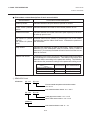
1
TEC Thermal Printer
B-570 SERIES
User's Manual
Document No. EM0-33013A
Original
Nov., 1993
(Revision Mar., 2000)
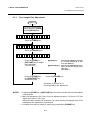
TABLE OF CONTENTS
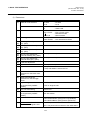
OWNER'S MANUAL ............................................. EM1-33035
PRODUCT DESCRIPTION ................................... EM10-33006A
MAINTENANCE MANUAL .................................... EM18-33010A
PRINTED IN JAPAN
Precaution
This service manual, intended for field engineers and technicians, is designed as a guide for
maintenance, service and repair of TOSHIBA TEC Thermal Printers on the market.
The following related manuals contain additional information on using the B-570 Series.
Please refer to the detail information for specific purposes. (For instance, please read carefully
the supply manual when media or ribbon is needed.)
They are available from TOSHIBA TEC sales headquarters.
• Interface/Communication Manual
• Supply Manual
• Specifications
Safety Summary
Personal safety in handling or maintaining the equipment is extremely important. Warnings and
Cautions necessary for safe handling are included in this manual. All warnings and cautions
contained in this manual should be read and understood before handling or maintaining the
equipment.
Safety Precaution
Energized electrical equipment is dangerous. Electrical shock from energized equipment can
cause death. Never work on energized equipment unless authorized to do so by a responsible
authority.
If emergency work on energized equipment is authorized, be sure that it is accomplished in strict
compliance with approved safety regulations.
The following safety precautions will help to ensure proper use of the printer:
• Turn off the printer before opening the top for any reason.
• Unplug the printer whenever you are working inside the printer.
• Keep your work environment static free.
PRINTED IN JAPAN
EO0-33004
TEC Thermal Printer
B-570-QQ SERIES
Owner’s Manual
Table of Contents
This equipment has been tested and found to comply with the limits for a Class A digital device,
pursuant to Part 15 of the FCC Rules. These limits are designed to provide reasonable protection
against harmful interference when the equipment is operated in a commercial environment. This
equipment generates, uses, and can radiate radio frequency energy and, if not installed and used in
accordance with the instruction manual, may cause harmful interference to radio communications.
Operations of this equipment in a residential area is likely to cause harmful interference in which case
the user will be required to correct the interference at his own expense.
(for USA only)
Changes or modifications not expressly approved by manufacturer for compliance could void the
user's authority to operate the equipment.
"This Class A digital apparatus meets all requirements of the Canadian Interference-Causing
Equipment Regulations."
"Cet appareil numérique de la classe A respecte toutes les exigences du Règlement sur le matériel
brouilleur de Canada."
(for CANADA only)
CAUTION:
To avoid injury, be careful not to catch or jam your fingers while opening or closing the cover.
CAUTION:
Do not touch moving parts. To reduce the risk that fingers, jewelry, clothing. etc., be drawn into the
moving parts, push the switch in the "OFF" position to stop movement.
Copyright © 2000
by TOSHIBA TEC CORPORATION
All Rights Reserved
570 Ohito, Ohito-cho, Tagata-gun, Shizuoka-ken, JAPAN
EM1-33035
Safety Summary
Safety Summary
Personal safety in handling or maintaining the equipment is extremely important. Warnings and Cautions
necessary for safe handling are included in this manual. All warnings and cautions contained in this
manual should be read and understood before handling or maintaining the equipment.
Do not attempt to effect repairs or modifications to this equipment. If a fault occurs that cannot be rectified
using the procedures described in this manual, turn off the power, unplug the machine, then contact your
authorized TOSHIBA TEC representative for assistance.
Meanings of Each Symbol
This symbol indicates warning items (including cautions).
Specific warning contents are drawn inside the symbol.
(The symbol on the left indicates a general caution.)
This symbol indicates prohibited actions (prohibited items).
Specific prohibited contents are drawn inside or near the symbol.
(The symbol on the left indicates “no disassembling”.)
This symbol indicates actions which must be performed.
Specific instructions are drawn inside or near the symbol.
(The symbol on the left indicates “disconnect the power cord plug from the outlet”.)
WARNING
Any other than the
specified AC voltage
is prohibited.
This indicates that there is the risk of death or serious injury if the
machines are improperly handled contrary to this indication.
Do not use voltages other than the
voltage (AC) specified on the rating
plate, as this may cause fire or
electric shock.
Prohibited
Do not plug in or unplug the power
cord plug with wet hands as this may
cause electric shock.
Prohibited
If the machines share the same
outlet with any other electrical
appliances which consume large
amounts of power, the voltage will
fluctuate widely each time these
appliances operate. Be sure to
provide an exclusive outlet for the
machine as this may cause the
machines to malfunction.
Prohibited
Do not place metal objects or
water-filled containers such as flower
vases, flower pots or mugs, etc. on
top of the machines. If metal objects
or spilled liquid enter the machines,
this may cause fire or electric
shock.
Prohibited
Do not insert or drop metal,
flammable or other foreign objects into
the machines through the ventilation
slits, as this may cause fire or electric
shock.
Prohibited
Do not scratch, damage or modify
the power cords. Also, do not place
heavy objects on, pull on, or excessively bend the cords, as this may
cause fire or electrical shock.
Disconnect
the plug.
If the machines are dropped or their
cabinets damaged, first turn off the
power switches and disconnect the
power cord plugs from the outlet, and
then contact your authorized
TOSHIBA TEC representative for
assistance. Continued use of the
machine in that condition may cause
fire or electric shock.
Disconnect
the plug.
Continued use of the machines in an
abnormal condition such as when the
machines are producing smoke or
strange smells may cause fire or electric shock. In these cases, immediately turn off the power switches and
disconnect the power cord plugs from
the outlet. Then, contact your authorized TOSHIBA TEC representative for
assistance.
(i)
EM1-33035
Safety Summary
Disconnect
the plug.
Connect a
grounding
wire.
If foreign objects (metal fragments,
water, liquids) enter the machines,
first turn off the power switches and
disconnect the power cord plugs from
the outlet, and then contact your
authorized TOSHIBA TEC representative for assistance. Continued
use of the machine in that condition
may cause fire or electric shock.
Disconnect
the plug.
When unplugging the power cords,
be sure to hold and pull on the plug
portion. Pulling on the cord portion
may cut or expose the internal wires
and cause fire or electric shock.
Ensure that the equipment is
properly grounded. Extension cables
should also be grounded. Fire or
electric shock could occur on
improperly grounded equipment.
No disassembling.
Do not remove covers, repair or
modify the machine by yourself. You
may be injured by high voltage, very
hot parts or sharp edges inside the
machine.
indicates that there is the risk of personal Injury or damage to
CAUTION This
objects if the machines are improperly handled contrary to this indication.
Precautions
The following precautions will help to ensure that this machine will continue to function correctly.
• Try to avoid locations that have the following adverse conditions:
* Temperatures out of the specification
* Direct sunlight
* High humidity
* Shared power source
* Excessive vibration
* Dust/Gas
• The cover should be cleaned by wiping with a dry cloth or a cloth slightly dampened with a mild
detergent solution. NEVER USE THINNER OR ANY OTHER VOLATILE SOLVENT on the plastic
covers.
• USE ONLY TOSHIBA TEC SPECIFIED paper and ribbons.
• DO NOT STORE the paper or ribbons where they might be exposed to direct sunlight, high temperatures, high humidity, dust, or gas.
• Ensure the printer is operated on a level surface.
• Any data stored in the memory of the printer could be lost during a printer fault.
• Try to avoid using this equipment on the same power supply as high voltage equipment or equipment likely to cause mains interference.
• Unplug the machine whenever you are working inside it or cleaning it.
• Keep your work environment static free.
• Do not place heavy objects on top of the machines, as these items may become unbalanced and fall
causing injury.
• Do not block the ventilation slits of the machines, as this will cause heat to build up inside the
machines and may cause fire.
• Do not lean against the machine. It may fall on you and could cause injury.
• Care must be taken not to injure yourself with the printer paper cutter.
• Unplug the machine when it is not used for a long period of time.
Request Regarding Maintenance
•
Utilize our maintenance services.
After purchasing the machine, contact your authorized TOSHIBA TEC representative for assistance
once a year to have the inside of the machine cleaned. Otherwise, dust will build up inside the
machines and may cause a fire or a malfunction. Cleaning is particularly effective before humid
rainy seasons.
•
Our preventive maintenance service performs the periodic checks and other work required to
maintain the quality and performance of the machines, preventing accidents beforehand.
For details, please consult your authorized TOSHIBA TEC representative for assistance.
•
Using insecticides and other chemicals
Do not expose the machines to insecticides or other volatile solvents. This will cause the cabinet or
other parts to deteriorate or cause the paint to peel.
(ii)
EM1-33035
TABLE OF CONTENTS
Page
1. INTRODUCTION .............................................................................. 1-1
1.1 Applicable Model ..................................................................................... 1- 5
1.2 Accessories ............................................................................................. 1- 5
2. SPECIFICATIONS ........................................................................... 2-1
2.1
2.2
2.3
2.4
Printer ...................................................................................................... 2- 1
Options .................................................................................................... 2- 2
Media ....................................................................................................... 2- 3
Ribbon ..................................................................................................... 2- 3
3. OVERVIEW ...................................................................................... 3-1
3.1 Front/Rear View....................................................................................... 3- 1
3.2 Operation Panel ...................................................................................... 3- 1
4. DIP SWITCH FUNCTIONS .............................................................. 4-1
5. INSTALLING THE PRINTER ........................................................... 5-1
6. LOADING THE MEDIA .................................................................... 6-1
7. LOADING THE RIBBON ................................................................. 7-1
8. INSERTING THE OPTIONAL FLASH MEMORY CARD................. 8-1
9. CARE/HANDLING OF THE MEDIA AND RIBBON ......................... 9-1
10. GENERAL MAINTENANCE .......................................................... 10-1
10.1
10.2
10.3
10.4
10.5
Cleaning ................................................................................................ 10- 1
Covers and Panels ................................................................................ 10- 1
Removing Jammed Paper ..................................................................... 10- 2
Threshold Setting .................................................................................. 10- 4
Auto Ribbon Saving Mode .................................................................... 10- 5
11. TROUBLESHOOTING ................................................................... 11-1
CAUTION:
1. This manual may not be copied in whole or in part without prior written permission of
TOSHIBA TEC.
2. The contents of this manual may be changed without notification.
3. Please refer to your local Authorized Service representative with regard to any queries
you may have in this manual.
Copyright © 1999
by TOSHIBA TEC CORPORATION
All Rights Reserved
570 Ohito, Ohito-cho, Tagata-gun, Shizuoka-ken, JAPAN
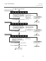
1. INTRODUCTION
EM1-33035
1.1 Applicable Model
1. INTRODUCTION
Thank you for choosing the TEC B-570 series thermal/transfer printer. This new generation high
performance/quality printer is equipped with the latest hardware including the newly developed high
density (12 dots/mm, 306 dots/inch) near edge print head. This will allow very clear print at a maximum
speed of 203.2 mm/sec. (8 inches/sec.). Other standard features include an automatic ribbon saver, a builtin rewinder/strip mechanism and an internal media supply spool. Combine this with an optional high speed
P.C. interface board which allows vastly reduced graphic data transfer times and you have a printer to suit
a variety of applications and environments.
This manual contains general set-up and maintenance information and should be read carefully to help
gain maximum performance and life from your printer. For most queries please refer to this manual and
keep it safe for future reference.
1.1 Applicable Model
•
B-572-QQ
Model name description
B - 5 7 2 - Q Q
QQ: North America
2: Thermal direct/Thermal transfer
1.2 Accessories
Head Cleaner
(24089500013)
Power Cord
PRI
NT
HEA
D C
LE
ANE
R
Owner's Manual
(EM1-33035)
Rewinder guide plate
(FMBD0034501)
Screw
(SM-4x6B)
Quality control report
1-1
Unpacking Procedure
2. SPECIFICATIONS
EM1-33035
2.1 Printer
2. SPECIFICATIONS
2.1 Printer
Model
Item
Supply voltage
Power consumption
Operating temperature range
Relative humidity
Print head
Printing methods
Print speeds
Maximum print width
Dispensing modes
Message display
Dimensions
Weight
Available bar code types
Fonts
Rotations
Standard interface
Optional interfaces
B-570-QQ
AC 100V ~ 120V +10%, -15%, 50/60Hz +2Hz, -2Hz
2A, 198W maximum (standby: 500mA, 51W maximum)
5°C ~ 40°C
25% ~ 85%RH (no condensation)
Thermal print head 12 dots per mm (306 dots per inch)
Thermal direct or Thermal transfer
76.2 mm/sec. (3 inch/sec.), 127 mm/sec. (5 inch/sec.),
203.2 mm/sec. (8 inch/sec.),
127.5 mm (5.02 inches)
Batch (Continuous), Strip (On-demand) and Cut modes
(Cut mode is only available when optional cutter is fitted.)
20 characters x 1 line
291 mm (width) x 460 mm (depth) x 308 mm (height)
19 kg (without media and ribbon)
JAN8, JAN13, EAN8, EAN8+2digits, EAN8+5digits
EAN13, EAN13+2digits, EAN13+5digits
UPC-E, UPC-E+2digits, UPC-E+5digits
UPC-A, UPC-A+2digits, UPC-A+5 digits
MSI, ITF, NW-7, CODE39, CODE93, CODE128, EAN128
PDF417, DATA MATRIX, Industrial 2 to 5
Times Roman (6 sizes), Helvetica (6 sizes), Presentation (1 size),
Letter Gothic (1 size), Prestige Elite (2 sizes), Courier (2 sizes),
OCR (2 types), Writable characters (40 types), Outline font (1 type)
0°, 90°, 180°, 270°
Serial interface (RS-232C)
Parallel interface (Centronics)
Expansion I/O interface
Flash memory card interface
High speed PC interface
2.2 Option
Option Name
Cutter module
Type
B-4205-QM
Usage
A stop and cut swing cutter
Source
See NOTE 1.
High speed PC interface kit
B-4800-PC-QM
This interface kit allows extremely high See NOTE 1.
speed information transfer between the
printer and PC.
Fanfold paper guide
module
B-4905-FF-QM
This is a paper guide exclusively used for See NOTE 1.
fanfold paper.
Attaching it in place of the standard paper
guide allows the printer to print on fanfold
paper.
D-RAM PC board
FMBC0067801
A 2MB RAM upgrade which enhances the See NOTE 2.
image handling capability of the printer.
Flash memory card
NOTES:
A flash ROM card (1MB and 4MB) for See NOTE 3.
storing logos, writable characters and formats.
1. Available from your nearest TOSHIBA TEC representative or TOSHIBA TEC Head Quarters.
2. Available from TOSHIBA TEC Parts Center.
3. When purchasing flash memory card locally, select one having the specifications described at page
8-1.
2-1
2. SPECIFICATIONS
EM1-33035
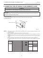
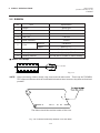
2.3 Media
2.3 Media
Stop
position
Refer to the following
NOTE 2.
Black Mark
(on reverse side)
I
Stop
position
Label
I
Tag paper
Black Mark
(on reverse side)
Tag paper
E
F
Cut
position
Cut
position
J
H
Reference
coordinate 1
Reference
coordinate 1
A
Reference
coordinate 2
G
Reference
coordinate 2
Feed direction
G
D
C
C
Fig. 2-1
Label dispensing mode
A
H
B
[Unit : mm]
Batch mode
Strip mode
Cut mode
A : Span of one label/tag
10.0 ~ 999.0
25.4 ~ 999.0
B : Label/tag length
C : Width including backing paper
D : Label width
E : Gap length
F : Black mark length (Tag paper)
G : Effective print width
Label Standard
H:
Max. memory
Effective print
TAG Standard
length
Max. memory
I : Print speed up/slow down area
J : Black mark length (Label)
Maximum effective length Standard
Max. memory
for on the fly issue
Outer roll diameter
Label
Thickness
Tag
8.0 ~ 997.0
Label: 38 ~ 999.0
Tag: 25.4 ~ 999.0
25.0 ~993.0
Item
NOTES:
2.0 ~ 20.0
6.0 ~ 298.6
6.0 ~ 995.0
8.0 ~ 298.6
8.0 ~ 997.0
23.4 ~ 997.0
50.8 ~ 140.0
47.8 ~ 137.0
6.0 ~ 20.0
2.0 ~ 20.0
2.0 ~ 10.0
10.0 ~ 128.0
23.0 ~ 298.6
21.4 ~ 298.6
23.0 ~ 991.0
21.4 ~ 995.0
234.0 ~ 298.6
23.4 ~ 298.6
23.4 ~ 997.0
23.4 ~ 997.0
1.0
Refer to the following NOTE 2.
149.3
661.3
ø200 Max.
0.13 ~ 0.17
0.15 ~ 0.29
1. The media specification other than above are unchanged.
2. When marking black marks on label rolls, the following requirements must be satisfied.
When the gap length is less than 4 mm:
The black mark length should be longer than the gap length.
When the gap length is 4 mm or more:
The black mark should not overlap the gap for more than 4 mm and the following label.
2.4 Ribbon
Type
Width
Length
Outer diameter
Spool type
NOTES: 1. "On the fly issue" means that the printer can draw and
print without stopping between labels.
68 mm ~ 134 mm
2. To ensure print quality and print head life use only
600 m
TOSHIBA TEC specified media and ribbons.
ø90 mm (max.)
3. When using the cutter ensure that label length B plus
inter label gap length E exceeds 35 mm. (i.e. label
pitch should be greater that 35 mm.)
4. When rewinding the media onto the take-up spool in
batch mode, the max. outer roll diameter should be 180
mm.
5. Use of rough media for the ribbon saving issue may
cause ribbon smudges.
2-2
3. OVERVIEW
EM1-33035
3.1 Front/Rear View
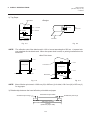
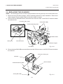
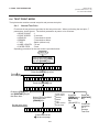
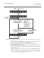
3. OVERVIEW
3.1 Front/Rear View
Front View
Rear View
Top Cover
Message Display (LCD)
Memory Card Slot
Outlet for the high speed PC
interface cable (Option)
Supply Window
Serial Interface
Connector
(RS-232C)
Parallel I/F Connector
(Centronics)
Operation Panel
Expansion I/O
Interface Connector
Media Outlet
AC Power Inlet
Power Switch
0: OFF
1: ON
Fig. 3-1
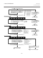
3.2 Operation Panel
Fig. 3-2
MESSAGE DISPLAY (LCD)
Displays messages in the language selected by DIP switch.
When power is turned on and it is ready to print, "ON LINE" is
displayed.
POWER LED (Green)
Lights when the power is turned on.
ON-LINE LED (Green)
1) Flashes when communicating with a host computer.
2) On while printing.
ERROR LED (Red)
Lights when a communication error occurs, when the media/
ribbon ends or the printer does not operate correctly.
FEED key
Feeds paper.
RESTART key
Resets the printer when paused or when an error occurs.
Used to set the threshold. (Refer to page 10-4)
PAUSE key
Pauses printing.
Message display shows "PAUSE" and an unprinted count.
Used to set the threshold. (Refer to page 10-4)
3-1
4. DIP SWITCH FUNCTIONS
EM1-33035
4. DIP SWITCH FUNCTIONS
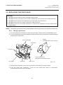
4. DIP SWITCH FUNCTIONS
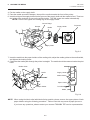
The DIP switches are located to the right of the supply shaft.
Supply Shaft
Ribbon Shaft
WARNING:
Turn the POWER OFF before switching the functions.
(1)
DIP SW 2
No.
1
2
3
4
5
6
7
8
(2)
ON/OFF
2
1
OFF
OFF
ON
ON
ON
OFF
ON
ON
OFF
ON
OFF
ON
OFF
ON
OFF
ON
8
7
OFF
OFF
ON
OFF
OFF
ON
ON
ON
Function
Transmission speed
2400 BPS
4800 BPS
9600 BPS
19200 BPS
1 bit
2 bit
7 bit
8 bit
without
with
EVEN
ODD
Stop bit length
Fig. 4-1
Data length
Parity check
Parity check (effective when DIP
SW #5 is set to ON.)
XON/XOFF (No XON is output at the power on time.) Data protocol
(XOFF is output at the power off time.)
READY/BUSY (DTR)
(No XON is output at the power on time.)
(No XOFF is output at the power off time.)
READY/BUSY (RTS)
(No XON is output at the power on time)
(No XOFF is output at the power off time.)
XON/XOFF + READY/BUSY
(XON is output at the power on time.)
(XOFF is output at the power off time.)
XON/XOFF (XON is output at the power on time.)
(XOFF is output at the power off time.)
DIP SW 1
No.
1
2
3
4
5
6
7
8
2
OFF
ON
OFF
ON
OFF
ON
OFF
ON
ON/OFF
OFF
ON
3
OFF
OFF
ON
ON
OFF
OFF
ON
ON
OFF
ON
OFF
ON
OFF
ON
OFF
ON
Without
With
4
OFF
OFF
OFF
OFF
ON
ON
ON
ON
English
German
French
Dutch
Spanish
Japanese
Italian
Not used
Without
With
Without
With
Must be set to OFF.
Function
Auto ribbon save function
Language to display LCD error
message
Auto media feed after a cut issue
(See page 6-5)
Use of the built-in rewinder/Head up
function in cut mode Refer to Note 2.
Must be set to OFF.
NOTES: 1. The shaded settings are the factory default settings. "OFF" means "OPEN".
2. The DIP switch #1-6 functions in accordance with equipment to be used.
3. If you would like to switch to READY/BUSY (DTR) or to READY/BUSY (RTS) of data protocol,
please contact your authorized TOSHIBA TEC representative.
4-1
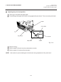
5. INSTALLING THE PRINTER
EM1-33035
5.1 INSTALLING THE PRINTER
5. INSTALLING THE PRINTER
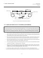
Connecting the Power Cord and Cables
WARNING!
Turn the POWER SWITCH to OFF before connecting the power cord or cables.
Serial I/F Cable (RS-232C)
Expansion I/O Cable
Parallel I/F Cable (Centronics)
High Speed PC Interface Cable (Option)
Power Cord
Fig. 5-1
5-1
6. LOADING THE MEDIA
EM1-33035
6. LOADING THE MEDIA
6. LOADING THE MEDIA
WARNING:
1. Do not touch moving parts. To reduce the risk that fingers, jewelry, clothing, etc., be drawn
into the moving parts, push the switch in the “OFF” position to stop movement.
2. To avoid injury, be careful not to catch or jam your fingers while opening or closing the cover.
The printer prints both labels and tags.
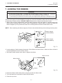
1. Turn off the power and open the top cover.
2. Turn the head lever to position 3, then release the ribbon shaft holder plate.
Top Cover
Ribbon Shaft Holder Plate
Head Lever
Fig. 6-1
NOTES: 1. When the head lever is turned to position 2, the print head is raised.
2. When the head lever is turned to position 3, the print head and the pinch roller are raised.
3. To allow printing the head lever must be set to position 1. (This ensures that the print head
and the pinch roller are closed.)
3. Turn the locking ring counter clockwise and remove the supply holder from the supply shaft.
NOTE: Do not turn the force the locking ring too far counterclockwise or it may come off the supply holder.
Supply Shaft
Locking Ring
Supply Holder
Fig. 6-2
6-1
6. LOADING THE MEDIA
EM1-33035
6. LOADING THE MEDIA
4. Put the media on the supply shaft.
5. Pass the media around the damper, then pull the media towards the front of the printer.
6. Insert the ridge of the supply holder into the groove of the supply shaft until the media is fixed. Then turn
the locking ring clockwise to secure the supply holder. This will centre the media automatically.
NOTE: Do not over tighten the locking ring of the supply holder.
Groove Ridge
Damper
Media
Supply Holder
Projection
Supply Shaft
Fig. 6-3
7. Insert the media into the paper holders of the media guide, adjust the media guides to the media width,
and tighten the locking screw.
8. Check that the media path through the printer is straight. The media should be centered under the print
head.
Media Guide
Media
Supply Holder
Media Guide
Paper Holder
Paper Holder
Print Head
Media
Locking Screw
Fig. 6-4
NOTE: When using the label rolled with labels facing outside, please remove the upper plates of both
paper holders using the following procedure. Failure to do this may cause a paper jam error.
If you have any questions, please contact your nearest TOSHIBA TEC service representative.
6-2
6. LOADING THE MEDIA
EM1-33035
6. LOADING THE MEDIA
■ Removing the paper holders' upper plates from the media guide
1 Remove the two T-4x8 screws to detach the media guide from the printer.
Media Guide
Screw (T-4x8)
Fig. 6-5
2 Remove the SM-3x6 screw or the SM-3x8 screw to detach the paper holders' upper plates from
the media guide.
(Right)
(Left)
Screw (SM-3x8)
Screw (SM-3x6)
Paper Holder
Paper Holder
Fig. 6-6
3 Attach the media guide back in position.
NOTE: Do not lose the removed upper plates because they are required when using the label rolled
with labels facing inside.
9. Set the black mark/feed gap sensor to the correct position by turning the adjusting knob. Turning the
knob right will move the sensor towards the center of the media while turning left will move it away from
the center of the media.
6-3
6. LOADING THE MEDIA
EM1-33035
6. LOADING THE MEDIA
■ An easy way to set the black mark sensor position
1 Pull the media about 500 mm out of the front of the printer, turn the media back on it's self and
feed it under the print head past the sensor so that the black mark can be seen from above.
2 Adjust the sensor position to that of the black mark (the upper hole indicates the position of the
black mark sensor).
Black Mark Sensor
Black Mark
Media
(Feed Gap Sensor)
Adjusting Knob
Fig. 6-7
NOTE: Make sure to set the sensor to detect the center of the black mark, otherwise a paper jam
error could occur.
■ Setting the feed gap sensor position
1 Adjust the sensor to detect on the gap (the lower hole indicates the position of the feed gap
sensor.)
(Black Mark Sensor)
Backing Paper
Media
Media
Feed Gap Sensor
Adjusting Knob
Fig. 6-8
6-4
6. LOADING THE MEDIA
EM1-33035
6. LOADING THE MEDIA
10. The media is now loaded and the sensor position is set.
Batch type:
Media
Fig. 6-9
NOTE: Set the selection switch to the STANDARD/STRIP position. Improper setting can affect the print
quality.
Strip type:
1 Remove enough labels from the leading edge media to leave 500 mm of backing paper
exposed.
2 Wind the backing paper onto the take-up spool and fix in position with the take-up clip.
(Wind the paper counter clockwise around the spool as this is the direction it rotates.)
3 Rotate the take-up spool anti-clockwise a few times to take up any slack in the backing paper.
Media
Take-up Spool
Front Plate
Take-up Clip
Black Screw
(HAA-0004001)
Backing Paper
Fig. 6-10
NOTES: 1. The backing paper is easier to feed back to the take-up spool if the front plate is removed.
2. When fitting the tace-up clip the longer side of the clip should be fitted into the shallow groove
on the take-up spool.
3. Set the selection switch to the STANDARD/STRIP position.
6-5
6. LOADING THE MEDIA
EM1-33035
6. LOADING THE MEDIA
Cutter type: Where a cutter is fitted load the media as standard and feed it through the cutter module.
NOTES: 1. Be sure to cut the backing paper of label. Cutting labels will cause the glue to stick to the cutter,
which may affect the cutter quality and shorten the cutter life.
2. If the top edge of label winds onto the platen in cut issue, set the DIP SW 1-5 to ON.
3. For the cutter type, the selection switch can be set to either position.
Media Outlet
Media
Cutter Module
Fig. 6-11
Built-in rewinder type:
1 Remove two black screws and front plate.
2 Fit the rewinder guide plate to the tear-off bar, then attach it with the sems screws.
Tear-off Bar
Rewinder Guide Plate
(FMBD0034501)
SM-4x6B Sems Screw
SM-4x6B Sems Screw
SM-4x8 Sems Screw
Adjustment Knob
Fig. 6-12
NOTES: Set the selection switch to the REWINDER position.
3 Follow the procedure for strip type.
4 Adjustment
If the label skews when using built-in rewinder unit, turn the adjustment knob of the rewinder
guide plate to correct the label feed. Clockwise turn moves the rewinder guide plate forward
and counterclockwise moves it backward.
* When labels skew to the right:
Loosen the SM-4x8 sems screw with a philips-head screw driver. Turn the adjustment knob
clockwise, and tighten the SM-4x8 screw when the rewinder guide plate is positioned
correctly.
* When labels skew to the left:
Loosen the SM-4x8 screw with a phillips-head screw driver. Turn the adjustment knob
counterclockwise, and tighten the SM-4x8 screw when the rewinder guide plate is positioned correctly.
6-6
7. LOADING THE RIBBON
EM1-33035
7. LOADING THE RIBBON
7. LOADING THE RIBBON
WARNING!
1. Do not touch moving parts. To reduce the risk that fingers, jewelry, clothing, etc., be drawn
into the moving parts, push the switch in the “OFF” position to stop movement.
2. To avoid injury, be careful not to catch or jam your fingers while opening or closing the cover.
There are two types of media available for printing on, these are standard media and direct thermal media
(a chemically treated surface). DO NOT LOAD a ribbon when using a direct thermal media.
1. When using a narrow width ribbon, slide the ribbon stoppers along the shafts to a position where the
ribbon will be centered when it is fitted. When changing from a narrow width to a wider one rotate the
ribbon stoppers by 90°, push them back to the correct position and then rotate back to lock.
NOTE: When attaching the ribbon stoppers, fit them to the shafts with the pinchers facing into the printer.
Ribbon Stopper
(FMHC0008801)
Ribbon Stopper
(FMHC0008801)
Fig. 7-1
2. Leaving plenty of slack between the spools, fit the ribbon as shown below. When the ribbon is fitted it
must be positioned over the ribbon sensor.
3. Wind both shafts towards each other to tighten the ribbon.
Ribbon Sensor
Ribbon Shafts
Ribbon
Ribbon
Fig. 7-2
4. Reset the ribbon shaft holder plate by aligning it with the ribbon shaft.
5. Turn the head lever clockwise to lower the print head.
6. Close the top cover.
7-1
8. INSERTING THE OPTIONAL FLASH MEMORY CARD
EM1-33035
8. INSERTING THE OPTIONAL FLASH MEMORY CARD
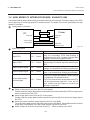
8. INSERTING THE OPTIONAL FLASH MEMORY CARD
WARNING!
Turn the power OFF when inserting or removing the flash memory card.
CAUTION:
To protect memory cards, discharge static electricity from your body by touching the printer rear
cover prior touching the memory cards.
1. Turn the power off.
2. Insert the flash memory card into the memory card slot at the rear of the printer.
3. Turn the power on.
Flash memory Card
Fig. 8-1
NOTES: 1. Be sure to protect a flash memory card when not in use in the printer by putting it in it's
protective cover.
2. Do not subject the card to any shocks or excessive forces.
3. Do not expose the card to extremes of heat by either storing in direct sunlight or close to a
heater.
4. Do not expose the card to excessive humidity by wiping it with a wet cloth or storing it in a damp
place.
5. Before inserting or removing the card, make sure that the power switch is turned off.
6. The following flash cards can be used. (The 1MB-card is read only and the 4MB card can read/
write.)
Capacity
1M Byte
4M Byte
Maker
Type
Device code
Maker code
D0H
1CH
Maxell
EF-1M-TB AA
Mitsubishi
MF81M1-GBDAT01
Maxell
EF-4M-TB CC
88H
B0H
Maxell
EF-4M-TB DC
ADH
04H
Centennial Technologies INC.
FL04M-15-11119-03
INTEL
IMC004FLSA
Simple TECHNOLOGY
STI-FL/4A
Mitsubishi
MF84M1-G7DAT01
PC Card KING MAX
FJN-004M6C
PC Card
FJP-004M6R
8-1
01H
A2H
89H
A0H
89H
9. CARE/HANDLING OF THE MEDIA AND RIBBON
EM1-33035
9. CARE/HANDLING OF THE MEDIA AND RIBBON
9. CARE/HANDLING OF THE MEDIA AND RIBBON
CAUTION:
Be sure to read carefully and understand the Supply Manual. Use only media and ribbon
which meet specified requirements. Use of non-specified media and ribbon may shorten the
head life and result in problems with bar code readability or print quality. All media and ribbon
should be handled with care to avoid any damage to the media, ribbon or printer. Read the
following guideline carefully.
• Do not store the media and ribbon for longer than the manufactures recommended shelf life.
• Store media rolls on the flat end, do not store them on the curved sides as this might flatten that side
causing erratic media advance and poor print quality.
• Store the media in plastic bags and always reseal after opening. Unprotected media can get dirty and
the extra abrasion from the dust and dirt particles will shorten the print head life.
• Store the media and ribbon in a cool, dry place. Avoid areas where they would be exposed to direct
sunlight, high temperature, high humidity, dust or gas.
• The thermal paper used for direct thermal printing must not have the specifications which exceed Na+
800 ppm, K+ 250 ppm and CL- 500 ppm.
• Some ink used on pre-printed labels may contain ingredients which shorten the print head's product life.
Do not use labels pre-printed with ink which contain hard substances such as carbonic calcium (CaCO3)
and kaolin (Al2O3, 2SiO2, 2H2O).
For further information please contact your local distributor or your media and ribbon manufacturer.
9-1
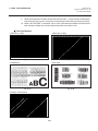
10. GENERAL MAINTENANCE
EM1-33035
10.1 Cleaning
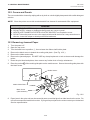
10. GENERAL MAINTENANCE
WARNING!
1. Be careful when handling the print head as it becomes very hot.
2. Care must be taken not to injure yourself with the printer paper cutter.
3. Do not touch moving parts. To reduce the risk that fingers, jewelry, clothing, etc., be drawn
into the moving parts, push the switch in the “OFF” position to stop movement.
4. To avoid injury, be careful not to catch or jam your fingers while opening or closing the cover.
10.1 Cleaning
To help retain the high quality and performance of your printer it should be regularly cleaned. The
greater the usage of the printer, the more frequent the cleaning. (i.e. low usage=weekly : high usage=daily).
1.
2.
3.
4.
5.
6.
Turn the power off.
Open the top cover.
Turn the head lever to raise the print head.
Remove the ribbon and media.
Clean the element of print head with print head cleaner.
Wipe the platen, feed roller and pinch roller with a cleaner moistened with alcohol.
Remove dust or foreign substances from the internal part of the printer, if any.
Element
Print Head
Pinch Roller
Print Head
Element
Feed Roller
Platen
Print Head Cleaner
(24089500013)
Fig. 10-1
WARNING!
1. Be sure to disconnect the power cord prior ot performing any maintenance.
2. Do not use any tool that may damage the print head.
3. DO NOT POUR WATER directly onto the printer.
10-1
10. GENERAL MAINTENANCE
EM1-33035
10.2 Covers and Panels
10.2 Covers and Panels
The covers should be cleaned by wiping with a dry cloth or a cloth slightly dampened with a mild detergent
solution.
NOTE: Clean the printer cover with an electrostatic free cleaner for automated office equipment.
WARNING!
1.
2.
3.
4.
DO NOT POUR WATER directly onto the printer.
DO NOT APPLY cleaner or detergent directly onto any cover or panel.
NEVER USE THINNER OR OTHER VOLATILE SOLVENT on the plastic covers.
DO NOT clean the panel covers or the supply window with alcohol as it may cause them to
discolor, loose their shape or develop structural weakness.
10.3 Removing Jammed Paper
1.
2.
3.
4.
5.
6.
Turn the power off.
Open the top cover.
Turn the head lever to position 3, then release the ribbon shaft holder plate.
Remove the black screw to detach the media guide plate. (See Fig. 10-2.)
Remove the ribbon and media.
Remove the jammed paper. DO NOT USE any sharp implement or tool as these could damage the
printer.
7. Clean the print head and platen, then remove any further dust or foreign substances.
8. Place the portion B of the media guide plate on the media sensor. Secure the media guide plate with
the black screw.
Media Sensor
Media Guide Plate
Black Screw
(HAA-0004001)
Fig. 10-2
9. Paper jams in the cutter unit can be caused by wear or residual glue from label stock on the cutter. Do
not use none specified media in the cutter. If you get frequent jams in the cutter contact your Authorized
Service representative.
10-2
10. GENERAL MAINTENANCE
EM1-33035
10.3 Removing Jammed Paper
■ Cleaning the Cutter Unit
WARNING!
1. Be sure to turn the power off before cleaning the cutter unit.
2. The cutters are sharp and care should be taken not to injure yourself when cleaning.
1.
2.
3.
4.
Loosen two screws and remove the cutter cover.
Remove the white screw and media guide.
Remove the jammed paper and trash.
Clean the cutter with dry cloth.
Media Guide
Screw
Fixed Cutter
White Screw
(24741710304)
Cutter Cover
Cutter Unit
Swing Cutter
Fig. 10-3
5. Assembling is reverse order of removal.
10-3
10. GENERAL MAINTENANCE
EM1-33035
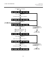
10.4 Threshold Setting
10.4 Threshold Setting
For the printer to maintain a constant print position it uses the transmissive sensor to detect the gap
between labels by measuring the amount of light passing through the media. When the media is preprinted, the darker (or more dense) inks can interfere with this process causing paper jammed errors.
To get around this problem a minimum threshold can be set for the sensor in the following way.
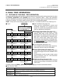
■ Threshold setting procedure
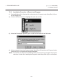
Turn the power ON.
O N
LI NE
(1)
(2)
(3)
The printer is in stand-by.
Load a media roll in the usual way.
Press the [PAUSE] key.
(4)
The printer enters the pause mode.
(5)
(6)
Press and hold the [PAUSE] key for at least 3
seconds in the pause state.
The sensor type is displayed.
(7)
Press the [FEED] key.
(8)
The reflective sensor (black mark sensor) is selected.
(9)
Press the [FEED] key again.
PAUSE
P A US E
PAUSE
T RA NS MIS S IVE
FEED
R EF LE CTI V E
FEED
T RA NS MIS S IVE
PAUSE
T RA NS MIS S IVE
(10) The transmissive sensor (feed gap sensor) is selected.
(11) Press and hold the [PAUSE] key.
(12) The media is advanced until the [PAUSE] key is
released.
(13) Release the [PAUSE] key when more than 1.5 labels
(tags) are advanced.
(Threshold setting is completed by this operation.)
P A US E
RESTART
O N
(14) Press the [RESTART] key.
(15) The printer is in stand-by.
L I NE
Command
O N
LI NE
(16) Send an issue command from the PC to the printer.
NOTES:
1. If the [PAUSE] key is released within 3 seconds whilst in pause state, paper will not feed.
2. Failure to feed more than 1.5 to 2 labels may result in an incorrect threshold setting.
3. While the print head is raised, the [PAUSE] key does not work.
4. Error such as paper end and cutter error are not detected during paper feed.
5. Selecting the transmissive sensor (for pre-printed labels) within software commands allows the printer to
detect the proper print start position correctly even when using pre-printed labels.
6. If the printer continues to print out of position after setting the threshold, adjust the feed gap sensor in the
system mode. Reset the threshold again. Make sure that the transmissive sensor (for pre-printed labels) is
selected in the feed and issue commands.
10-4
10. GENERAL MAINTENANCE
EM1-33035
10.4 Threshold Setting
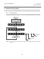
■ Threshold setting procedure (For firmware version 2.5 or earlier)
1 Turn the power on.
2 Load the pre-printed label. (Any position)
3 Press the [PAUSE] key once.
4 Hold down the [PAUSE] key for more than 3 seconds and it will begin to feed. After it has fed the 2 label,
release the [PAUSE] key.
5 Press the [RESTART] key for ON LINE mode.
6 Threshold setting is now completed.
NOTES: 1. If the [PAUSE] key is not held down for more than 3 seconds in PAUSE mode the threshold
will not be set.
2. If the [PAUSE] key is released before 2 labels have been issued the setting may not be correct
and will have to be re-set.
10.5 Auto Ribbon Saving Mode
Auto ribbon saving function is activated when it is selected by DIP switch (Refer to page 4-1) and no
print area extends more than 20 mm.
NOTE: According to the relation between the outer diameter of rewound ribbon and print speed,
ribbon loss per saving varies as follows:
Print speed
Ribbon loss
3"/sec.
Approx. 5 mm
5"/sec.
Approx. 8 mm
8"/sec.
Approx. 17 mm
10-5
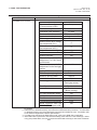
11. TROUBLESHOOTING
EM1-33035
11. TROUBLESHOOTING
11. TROUBLESHOOTING
WARNING!
If you cannot solve a problem with the following solutions, do not attempt to repair it yourself. Turn
the power off, unplug the printer, then contact your Authorized Service representative for assistance.
Error Message
PAPER JAM
****
Problem
Solution
1. The media is not fitted correctly.
2. The media path is jammed and
does not feed smoothly.
3. The installed media type does not
match the selected sensor.
4. The black mark position on the
media does not match the sensor
position.
5. The installed media size is different
from the programmed size.
6. The feed gap sensor cannot see
the difference between the print
area and the gap.
1. Re-fit the media correctly.
➔ Press the [RESTART] key.
2. Remove the cause of the jam and
replace the media correctly.
➔ Press the [RESTART] key.
3. Turn the power off then on again.
Select the correct sensor.
➔ Feed the media.
4. Adjust the sensor position.
➔ Press the [RESTART] key.
5. Turn the power off then on again.
Set the correct media size.
➔ Feed the media.
6. Set the threshold (see page 10-4).
Else
Turn the power off and call your
Authorized Service representative.
HEAD OPEN
****
Feed or printing has been attempted
while the print head is raised.
Lower the print head.
➔ Press the [RESTART] key.
NO PAPER
****
The media has run out.
Load new media.
➔ Press the [RESTART] key.
NO RIBBON
****
The ribbon has run out.
Load a new ribbon.
➔ Press the [RESTART] key.
REWIND FULL
****
Too much backing paper or media is
wound on the internal take-up spool.
Remove the backing paper or media
from the internal take-up spool.
Then press the [RESTART] key.
11-1
11. TROUBLESHOOTING
EM1-33035
11. TROUBLESHOOTING
Error Message
Problem
Solution
EXCESS HEAD
TEMP
The print head is too hot.
Turn the power off and decrease the
print head temperature.
HEAD ERROR
This message is displayed when
sending the head broken check
command ([ESC] HD001 [LF] [NUL])
and the print head has a broken
element.
1. Restart the printing by pressing the
[RESTAERT] key.
2. Replace the print head.
RIBBON ERROR
****
There is a fault with the ribbon sensor.
Turn the power off. Contact your
Authorized Service representative.
CUTTER ERROR Media is jammed in the cutter.
****
Remove the jammed media and feed
the undamaged media through the
cutter.
➔ Press the [RESTART] key.
Else
Turn the power off and contact your
Authorized Service representative.
FLASH WRITE
ERROR
An error has occurred when loading
data onto a flash memory card.
1. Turn the power off, re-seat the flash
memory card and try again.
2. Replace the flash memory card and
retry.
3. Turn the power off and contact your
Authorized Service representative.
FORMAT ERROR
An error has occurred while formatting
a flash memory card.
1. Turn the power off, re-seat the flash
memory card and try again.
2. Replace the flash memory card and
retry.
3. Turn the power off and contact your
Authorized Service representative.
FLASH MEMORY No more data can be saved in the
FULL
flash memory card.
Replace the card with a new one and
re-send data.
(Only 1MB and 4MB cards can be
used.)
COMMUNICATION A communication error has occurred
ERROR
with the host.
Turn the power off then on again or
press the [RESTART] key.
Check the program data.
➔ Call your Authorized Service representative if necessary.
11-2
11. TROUBLESHOOTING
EM1-33035
11. TROUBLESHOOTING
Problem
Error Message
example)
PC001; 0A00,
Command error
Solution
When an error is detected in a command 20 bytes of the command are
displayed.
(ESC, LF, NUL are not displayed.)
Correct the command and re-send it
again.
Hardware or software trouble.
Turn the power off then on again. If the
problem still exists turn the power off
and contact your Authorized Service
representative.
0300, 2, 2
Other Error
Message
NOTE: If an error is not cleared by pressing the [RESTART] key, the power must be switched off then
on again.
After the power has been switched off and on, all print data in the printer is cleared.
**** denotes a remaining count of unprinted labels.
Problem
Solution
No print.
1. Check that media and the ribbon is loaded correctly.
2. Check whether the print head is set correctly or not.
3. Check the cabling between the printer and the host.
Dots missing in the print.
Dirty print head. ➔ Clean the print head.
Call your Authorized Service representative if necessary.
Unclear (or blurred) printing.
1. Dirty print head. ➔ Clean the print head.
2. Bad or faulty ribbon. ➔ Replace ribbon.
3. Poor media quality. ➔ Change media type.
Power does not come on.
1. Plug power cord into an AC socket.
2. Check the circuit breakers or fuses.
3. Plug another appliance into the AC socket to check if
there is power supplied.
Call your Authorized Service representative if necessary.
Printer does not cut.
Check for a paper jam in the cutter.
Call your Authorized Service representative if necessary.
You see a raised nap where the media 1. Clean the cutter blades.
has been cut.
2. The blades are worn.
➔ Call your Authorized Service representative.
11-3
E
PRINTED IN JAPAN
EM1-33035
TEC Thermal Printer
B-570 SERIES
Product Description
Document No. EM10-33006A
Original
Nov., 1993
(Revised Feb., 2000)
Table of Contents
PRINTED IN JAPAN
EM10-33006A
(Rivision Date Apr. 28, '95)
TABLE OF CONTENTS
Page
1. OUTLINE OF THE SYSTEM .............................................................................. 1- 1
1.1 FEATURES OF THE B-570 SERIES .......................................................... 1- 1
1.2 DESCRIPTION OF MODEL NUMBER ........................................................ 1- 1
1.3 OVERVIEW AND DIMENSIONS (APPROXIMATE) ................................... 1- 2
1.4 BASIC SPECIFICATIONS .......................................................................... 1- 3
1.5 ELECTRONICS SPECIFICATIONS ............................................................ 1- 5
2. SUPPLY SPECIFICATIONS ............................................................................... 2- 1
2.1 MEDIA ......................................................................................................... 2- 1
2.2 RIBBON ...................................................................................................... 2- 3
2.3 CARE AND HANDLING OF THE MEDIA AND RIBBON ............................ 2- 4
3. OPTIONAL KIT ................................................................................................... 3- 1
3.1 CUTTER MODULE : B-4205-QM ................................................................ 3- 1
3.2 HIGH SPEED PC INTERFACE BOARD : B-4800-PC-QM ......................... 3- 2
3.3 MEMORY MODULE .................................................................................... 3- 3
3.4 FLASH MEMORY CARD ............................................................................ 3- 3
3.5 FANFOLD PAPER GUIDE MODULE: B-4905-FF-QM ............................... 3- 3
CAUTION:
1. This manual may not be copied in whole or in part without prior written permission of TOSHIBA TEC.
2. The contents of this manual may be changed without notification.
3. Please refer to your local Authorized Service representative with regard to any queries you may have
in this manual.
Copyright © 1999
by TOSHIBA TEC CORPORATION
All Rights Reserved
570 Ohito, Ohito-cho, Tagata-gun, Shizuoka-ken, JAPAN
EM10-33006A
(Revision Date: Feb. 10. 2000)
1.1 FEATURES OF THE B-570 SEREIS
1. OUTLINE OF THE SYSTEM
1. OUTLINE OF THE SYSTEM
1.1 FEATURES OF THE B-570 SERIES
1) Various bar codes, characters and graphic data can be printed using both thermal transfer and
thermal direct methods.
This printer can also print writable characters and logos at designated coordinates by using a graphic
command.
2) The RS-232C and Centronics are available as standard interfaces between the printer and a PC. In
addition, a flash memory card interface for data storage and an expansion interface for connecting
external devices except PCs are provided.
3) A 16-bit CPU and a Gate Array equipped with several peripheral LSIs realizes high system
performance.
4) With the element positioned at the edge of the print head, print quality is improved because the media
passes straight through. No adjustment of media thickness or printing pressure is necessary.
A high dot density of 12 dots/mm produces a clear print and the heat history control system optimizes
applied pulse signal to the head.
5) This printer accommodates a max. format size of 138 mm wide, by 997 mm long and a max. print
speed of 203.2 mm/sec.
6) High throughput can be obtained with "on-the-fly" formatting.
7) Installation space is minimized because the media is loaded internally.
8) The metal cover and damper provide a heavy-duty enclosure.
9) A strip unit and rewinder are provided as standard equipment on this printer. And a high-speed ribbon
saving function which economizes ribbon usage is available.
10) Optional devices such as a cutter module, high speed interface board, flash memory card (1MB or
4MB) and a memory module (max. 4MB) are available.
NOTE: Every size is written in millimeter (mm) in this manual. To obtain the size in inch, divide by 25.4.
1.2 DESCRIPTION OF MODEL NUMBER
B - 572 - QP
Destination Code:
QQ : North America Bloc
QP : Europe Bloc
Printing Method:
Thermal direct or Thermal transfer
1-1
EM10-33006A
1. OUTLINE OF THE SYSTEM
1.3 OVERVIEW AND DIMENSIONS (APPROXIMATE)
1.3 OVERVIEW AND DIMENSIONS (APPROXIMATE)
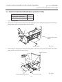
1.3.1
Front View/Rear View
Front View
Rear View
Top Cover
Outlet for the high speed PC
interface cable (Option)
Memory Card Slot
Message Display (LCD)
Serial Interface
Connector
(RS-232C)
Supply Window
Parallel I/F
Connector
(Centronics)
Power Switch
O : OFF
I : ON
Operation Panel
Media Outlet
Expansion I/O
Interface
Connector
AC Power Inlet
Fig. 1-1
1.3.2
Fig. 1-2
Operation Panel
MESSAGE DISPLAY (LCD)
Displays messages in the language selected DIP switch.
When power is turned on and it is ready to print, "ON LINE" is displayed.
POWER LED (Green)
Lights when the power is turned on.
ON-LINE LED (Green)
1) Flashes when communicating with a host computer.
2) On while printing.
POWER
ON LINE
ERROR
ERROR LED (Red)
Lights when the printer does not operate correctly.
FEED Button
Feeds paper.
RESTART Button
FEED
RESTART PAUSE
Resets the printer when paused or when an error occurs.
Used to set the threshold. (Refer to Owner's Manual)
PAUSE Button
Fig. 1-3
1.3.3
Pauses printing.
Message display shows "PAUSE" and an unprinted count.
Used to set the threshold. (Refer to Owner's Manual)
Dimensions (Approximate)
Standard
:
With cutter module :
291 mm (W) x 460 mm (D) x 308 mm (H)
291 mm (W) x 521 mm (D) x 308 mm (H)
1-2
EM10-33006A
(Revision Date: Feb. 10. 2000)
1.4 BASIC SPECIFICATIONS
1. OUTLINE OF THE SYSTEM
1.4 BASIC SPECIFICATIONS
1) Printing method ........ Thermal direct printing or thermal transfer printing
For the thermal transfer printing it may occur that horizontal lines printed within 20 mm from the
print start position of the first label become lighter than other. Please adjust the print tone
according to what you print.
2) Print head (5 inches)
1 Total number of dots .... 1536 dots
2 Dot density ................... 12 dots/mm
3 Effective print width .... 127.5 mm
4 Thermal pitch ............. 0.083 mm
3) Print speed ........................ 76.2 mm/sec., 127 mm/sec., 203.2 mm/sec. (selectable)
NOTE: These print speeds are available when printing ratio is less than 15% of the entire label
or tag paper.
4) Format size (W) x (L) ......... Label:
137.0 x 995.0 max.
Tag Paper: 137.0 x 997.0 max.
5) Issuing mode ..................... Batch or Strip printing (standard)
Auto cut (Auto cut mode is only available when an optional cutter is
attached.)
6) Type of bar code
1 UPC-A, UPC-A+2digits, UPC-A+5digits
2 UPC-E, UPC-E+2digits, UPC-E+5digits
3 EAN8, EAN8+2digits, EAN8+5digits, EAN13,
8
9
0
A
B
C
D
E
EAN13+2digits, EAN13+5digits, EAN128
4
5
6
7
JAN8, JAN13
NW-7
CODE39 (standard/full ASCII)
CODE93, CODE128 (auto code switch with/without)
ITF
MSI
Data Matrix
PDF417
Industrial 2 or 5
Customer Bar Code
F RM4SCC
(ROYAL MAIL 4STATE
CUSTOMER CODE)
G
H
I
Priority Customer Bar Code J
POSTNET
K
KIX CODE
Micro PDF
Maxi Code
QR Code
CP Code
7) Bar code rotation ............... 0°, 90°, 180°, 270°
8) Magnification of bar code
■ UPC/EAN/JAN/CODE93/128/PDF417 .......... Up to 6 modules can be automatically calculated
using 1-module width disignation (1 to 15 dots).
Dots/Module
2
3
4
5
6
7
8
Min. Module Width (mm)
–
0.25
0.33
0.42
0.50
0.58
0.66
Magnification (times)
–
0.76
1
1.27
1.52
1.76
2
0.166
0.25
0.33
0.42
0.50
0.58
0.66
9
10
11
12
13
14
15
Min. Module Width (mm)
–
–
–
–
–
–
–
Magnification (times)
–
–
–
–
–
–
–
0.747
0.83
0.91
1.00
1.08
1.16
1.25
Bar code
UPC-A/E
EAN8/13
JAN8/13
CODE93
EAN128
CODE128
PDF417
Min.Module Width (mm)
Dots/Module
Bar code
UPC-A/E
EAN8/13
JAN8/13
CODE93
EAN128
CODE128
PDF417
Min.Module Width (mm)
1-3
EM10-33006A
(Revision Date Nov. 11, '94)
1.4 BASIC SPECIFICATIONS
1. OUTLINE OF THE SYSTEM
■ NW-7/CODE39/ITF/MSI/Industrial 2 of 5 ...... The width of narrow bars, wide bars and spaces
can be optionally changed in a range of 1 to 99
dots.
■ Data Matrix .................................................... The width of one cell can be changed in a range of
1 to 99 dots.
9) Type of characters
1 Times Roman medium (8, 10 point)
8 Letter Gothic medium (9.5 point)
2 Times Roman bold (10, 12, 14 point)
9 Prestige Elite medium (7 point)
3 Times Roman Italic (12 point)
0 Prestige Elite bold (10 point)
4 Helvetica medium (6, 10, 12 point)
A Courier medium (10 point)
5 Helvetica bold (12, 14 point)
B Courier bold (12 point)
6 Helvetica Italic (12 point)
C OCR-A, B (12 point)
7 Presentation bold (18 point)
D Outline font (Helvetica bold)
E Writable characters (40 types) (224 char./types)
10) Character code
1 PC-850
2
PC-8
11) Character magnification
1 Regular font: 0.5 ~ 9.5 times (magnified by 0.5 times in each direction)
2 Outline font : 2.0 ~ 85.0 mm (magnified by 0.1 mm in each direction)
12)
13)
14)
15)
NOTE: When the outline font size is large, the ribbon may winkle according to the quality of the
ribbon or print tone.
White or black background ........ All types of characters are available
Character rotation .................................. 0°, 90°, 180°, 270°
Character strings rotation ...................... 0°, 90°, 180°, 270°
Type of line
1Horizontal line 2Vertical line 3Slant line 4Square 5Rounded Rectangle 6Circle
16) Line width .............................................. 1 dot to 12 dots can be specified (in units of 0.1 mm)
Guaranteed only when a line has more than 3 dots.
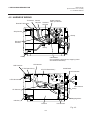
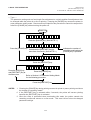
17) Mechanism
1 Batch mechanism
This is the standard mechanism which let the printer print continuously without winding the label
and tag paper. By attaching the rewinder guide printed media can be wound onto the take-up
spool. The auto-cut function is available when the optional cutter module is installed.
2 Strip mechanism
A printed label is separated from its backing paper by the stripf shaft. The next label will not
be printed until the preceding label is taken away. The backing paper is wound onto the takeup spool.
Ribbon
Label
Ribbon End
Sensor
Strip Sensor
Pinch
Roller
Print Head
Platen
Strip Shaft
Take-up Spool
Paper Feed
Sensor Roller
Rewind Full
Sensor
Fig. 1-4
1-4
EM10-33006A
(Revision Date: Feb. 10. 2000)
1.5 ELECTRONICS SPECIFICATIONS
1. OUTLINE OF THE SYSTEM
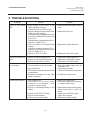
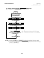
3 Auto cut mechanism
When the cutter module is installed, the backing paper and tag paper are cut individually (stop
and cut). Minimum cut length is 25.4 mm (tag paper) or 38 mm (label).
Ribbon
Tag
Ribbon End
Sensor
Cutter
Pinch
Roller
Print Head
Paper
Sensor
Platen
Feed
Roller
18) Power supply
QQ model: AC 100 ~ 120 V + 10%, -15%, 50/60Hz ± 2Hz
QP model: AC 220 ~ 240 V + 10%, -15%, 50Hz ± 2Hz
19) Current consumption
Printing:
198 W max., QQ model: 2 A max., QP model: 1 A max.
(Stand by: 51 W, QQ model: 500 mA, QP model: 250 mA)
20) Rush current ...... 30A or less
1.5 ELECTRONICS SPECIFICATIONS
1) CPU ................... µPD70236AGD-16-588
2) Memory
1 Program + Character generator:
Flash ROM 1 MB
2 Backup:
EE-PROM 128 Bytes
3 Image buffer + Work: D-RAM 2MB (max. 4MB: option)
3) Interface
1 RS-232C interface
(1) Communication mode:
Full-duplex
(2) Transmisson speed:
2400,4800,9600,19200 BPS (selectable)
(3) Synchronization:
start-stop synchronization
(4) Transmission parameter
■ Parity:
None, EVEN, ODD
■ Start bit:
1-bit
■ Stop bit:
1-bit or 2-bit
■ Word length:
7-bit or 8-bit
1-5
Fig. 1-5
EM10-33006A
1. OUTLINE OF THE SYSTEM
1.5 ELECTORONICS SPECIFICATIONS
(5) Error detection
■ Parity check:
VRC (Vertical parity check)
■ Framing error: This error occurs when no stop bit is found in the frame specified starting
with the start bit.
■ Overrun error: This error occurs when subsequent data is input before the data input to
the UART from the host is read by the printer.
(6) Data entry code: ASCII, 8-bit code for European characters, 8-bit code for graphic
(7) Receiving buffer: 5KB
(8) Protocol
■ XON/XOFF (DC1/DC3) protocol
• When initialized after power on, this printer becomes ready to receive data and sends
an XON code (11H). (Trasmission or non-transmission of XON code is selectable
by means of the DIP switch.)
• The printer sends an XOFF code (13H) when the blank positions in the receive buffer
becomes 800 Bytes or less.
• The printer sends an XON code (11H) when the blank positions in the receive buffer
are 2KB or more.
• When there are no blank positions in the receive buffer, the printer discards data
received which exceeds the receive buffer capacity, without storing it in the buffer.
(After detecting the XOFF code, the host computer must stop transmission before the
printer receive buffer becomes full.)
• The printer sends an XOFF code (13H) at power off time. (XOFF code send is
selectable with Dip switch.)
■ READY/BUSY (DTR) protocol
• When initialized after power on, this printer becomes ready to receive data and
converts the DTR signal to "High" level (READY).
• The printer converts the DTR signal to "Low" level (BUSY) when the blank positions
in the receive buffer amount to 800 Bytes or less.
• The printer converts the DTR signal to "High" level (READY) when the blank positions
in the receive buffer amount to 2KB or more.
• When there are no blank position in the receive buffer, the printer discards data
received which exceed the receive buffer capacity, without storing it in the buffer. (After
detecting a BUSY signal, the host computer must stop transmission before the printer
receive buffer becomes full.)
■ XON/XOFF (DC1/DC3) protocol + READY/BUSY (DTR) protocol
• When initialized after power on, this printer becomes ready to receive data and
converts the DTR signal to "High" level (READY). The printer sends an XON code
(11H).
• When the blank positions in the receive buffer are 800 Bytes or less, the printer
converts the DTR signal to "LOW" level (BUSY) and sends an XOFF code (13H).
• When the blank positions in the receive buffer are 2KB or more, the printer converts
the DTR signal to "High" level (READY) and sends an XON code (11H).
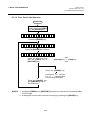
• When there are no blank positions in the receive buffer, the printer discards data
received which exceeds the receive buffer capacity, without storing it in the buffer.
(After detecting the XOFF code or BUSY signal, the host computer must stop
transmission before the printer receive buffer becomes full.)
• The printer sends an XOFF code (13H) at power off time.
1-6
EM10-33006A
(Revision Date: Aug. 5 '99)
1.5 ELECTORONICS SPECIFICATIONS
1. OUTLINE OF THE SYSTEM
■ READY/BUSY (RTS) Protocol
• When initialized after power on, this printer becomes ready to receive data and converts
the RTS signal to "High" level (READY).
• The printer converts the RTS signal to “Low” level (BUSY) when the blank positions in
the receive buffer amount to 800 Bytes or less.
• The printer converts the RTS signal to “High” level (READY) when the blank positions
in the receive buffer amount to 2 KB or more.
• When there are no blank position in the receive buffer, the printer discards data received
which exceed the receive buffer capacity, without storing it in the buffer. (After detecting
a BUSY signal, the host computer must stop transmission before the printer receive
buffer becomes full.)
• Both the DTR signal output from the printer and the DSR signal output from the PC are
always “High”.
NOTES:1. When performing the flow control with Windows, in the port setting screen,
select “Hardware” for flow control. [set to the READY/BUSY (RTS) protocol]
2. Under the READY/BUSY (DTR) protocol, after turning the printer power ON,
send data 200ms after the DTR signal is converted to “High” level (READY).
And under the READY/BUSY (RTS) protocol, after turning the printer power
ON, send data 200ms after the RTS signal is converted to “High” level (READY).
1-7
EM10-33006A
(Revision Date: Aug. 5 '99)
1.5 ELECTRONICS SPECIFICATIONS
1. OUTLINE OF THE SYSTEM
(9) Pin description
Pin No.
Signal
1
FG (Framed Ground)
2
RD (Received Data)
3
TD (Transmit Data)
4
CTS (Clear to Send
5
RTS (Request to Send)
6
DTR (Data Terminal Ready)
7
SG (Signal Ground)
20
DSR (Data Set Ready)
(10) Interface circuit
■ Input circuit
RD
CTS
DSR
■ Output circuit
SN75189 or equivalent
■ Signal level
Input voltage
Output voltage
I/O
Description
- Ground line for circuit protection.
Data line from which the priter receives data
from the host (receive data line).
I
Logic "1" is "Low", and "0" "High".
It is LOW (MARK) while no data is being sent.
Data line from which the printer sends data to
the host (send data line).
O Logic "1" is "Low", and "0" "High".
It is LOW (MARK) while no data is being sent.
Input signal from the host.
I
It must be "High" for the printer to send data.
Output signal to the host.
(1) READY/BUSY (DTR) protocol
It indicates there is data to send to the
host.
After power is ON, it is always "High".
(2) READY/BUSY (RTS) protocol
O
Indicates whether the printer is ready to
receive data.
The signal is at the Low level when the
data amount in the data buffer is near
full, and at the high level when near
empty.
Output signal to the host.
(1) READY/BUSY (RTS) protocol
It indicates there is data to send to the
host.
After power is ON, it is always "High".
O (2) READY/BUSY (DTR) protocol
Indicates whether the printer is ready to
receive data amount in the data buffer is
near full, and at the high level when near
empty.
- Ground line for all data and control signals.
Input signal from the host.
I
It must be "High" for the printer to receive
data.
SN75188 or equivalent
TD
RTS
DTR
"H" ..................... + 3V
"L" ...................... - 3V
"H" ..................... + 6V
"L" ...................... - 6V
1-8
Fig. 1-6
~ + 15V
~ -15V
~ + 13V
~ -13V
EM10-33006A
1. OUTLINE OF THE SYSTEM
1.5 ELECTORONICS SPECIFICATIONS
2 Centronics interface
(1) Data input method: 8-bit parallel (DATA 1 ~ 8)
(2) Control signals:
ACK, BUSY, PAUSE, DATA;STB, INPUT; PRIME, FAULT, PE
(3) Data input code:
ASCII, JIS 8-bit code for European characters, 8-bit code for graphic
(4) Receiving buffer:
5KB
(5) Input/Output crcuit configuration and Input/Output conditions
Type
Configuration
Signal Name
SN74LS14 or equivalent
+5V
DATA 1 ~ 8
Input
+5V
INPUT•PRIME
DATA•STB
Output
1K
SN74LS14 or equivalent
1K
100P
SN7406 or equivalent
BUSY
FAULT
PAUSE
ACK
PE
Logical level (input)
"1" = 2~5 V
"0" = 0~0.4 V
+5V
Logical level (input)
"1" = 2.4~5 V
"0" = 0~0.4 V
1K
100P
Fig. 1-7
3 External I/O interface
(1) Interface circuit
■ Input circuit
External controller, etc.
Printer
COM1
Vcc
IN0
R
~
~
IN4
R
Fig. 1-8
Photo-coupler
TPL521 (TOSHIBA)
There are five input circuits, and each input is a current loop using a photo-coupler. The anode of the
photo-coupler is connected to common pin COM1 in each of the five circuits. Each cathode is
independent. The voltage of Vcc is 24 V (max.) while the diode operating current is 16 mA.
1-9
EM10-33006A
1. OUTLINE OF THE SYSTEM
1.5 ELECTRONICS SPECIFICATIONS
■ Output circuit
External controller, etc.
(In case of photo-coupler)
Printer
OUT0
Vcc
~
~
OUT5
COM2
Fig. 1-9
There are six output circuits, and each output is an open collector. The voltage of Vcc is 24 V (max.)
while the operating current is 150 mA.
For other details, please refer to the Expansion I/O specification.
4)
Sensor/switch
1 Head up switch (micro switch)
This switch, attached at the lower left of the print head as viewed from the media outlet, detects
that the print head is ready to print (head is down). When the head lever is lowered, the head
down cam pushes up the print head, the micro switch is turned on and the print head prepares
to print.
2 Paper sensor
This sensor is comprised of the black mark sensor and feed gap sensor. It is positioned 92.1
mm from the platen.
The sensor position is adjustable according to the media width. It moves toward the main
frame a max. of 70 mm by turning the knob counterclockwise.
■ Black mark sensor (Reflective sensor)
This sensor detects the difference of potential between the black mark and tag paper to
find the print position of the tag paper.
It is located at the home position with the tag paper or print head before shipment.
Side detection (max.)
Center detection
20.5 mm
Center
Center
70 mm
90.5 mm
Tag Paper
Black Mark
Knob
Tag Paper
Black Mark
Knob
Feed Gap Sensor
Feed Gap Sensor
Black Mark Sensor
Main Frame
Black Mark Sensor
Fig. 1-10
Main Frame
1-10
Fig. 1-11
EM10-33006A
1. OUTLINE OF THE SYSTEM
1.5 ELECTRONICS SPECIFICATIONS
■
Feed gap sensor (Transmissive sensor)
This sensor detects the difference in potential between the backing paper and the
label to find the print position of the label. The feed gap sensor is located 8 mm to
the right of the black mark sensor.
Home position
Side detection limit position
Center of Label
70 mm
Home Position
Home Position
Center of Label
8 mm
8 mm
Label
28.5 mm
Backing Paper
Feed Gap Sensor
Black Mark Sensor
Main Frame
Label
Backing Paper
98.5 mm
Knob
Feed Gap Sensor
Black Mark Sensor
Knob
Main Frame
Fig. 1-12
Fig. 1-13
3 Strip sensor (Transmissive sensor)
This sensor detects whether or not the label has been removed and controls the label feed.
It is positioned 13.7 mm from the platen.
Strip Sensor (Tr)
Strip
Sensor (LED)
13.7 mm
Print Head
Platen
Strip Shaft
Fig. 1-14
Backing Paper
4 Ribbon end sensor (Transmissive sensor)
When printing in thermal transfer mode, this sensor detects the difference in potential
between the ribbon and the ribbon end to indicate the ribbon end. It is positioned 94.8 mm
from the platen and the detection point is 76.5 mm from the main frame.
Ribbon
Ribbon End Sensor (Tr)
Ribbon End Sensor (LED)
Print Head
Pinch Roller
Platen
94.8 mm
1-11
Feed Roller
Fig. 1-15
EM10-33006A
1. OUTLINE OF THE SYSTEM
1.5 ELECTRONICS SPECIFICATIONS
5
Rewind full sensor (Transmissive sensor)
This sensor detects excessive winding when winding backing paper or label onto the takeup spool. It is positioned 195.3 mm (Tr side) and 150.9 mm (LED side) from the platen, and
the detection point is 92.5 mm from the main frame. Excessive winding is detected when
backing paper blocks the light from the LED.
Print Head
Take-up Spool
Platen
Rewind Full
Sensor (Tr)
Backing Paper
Rewing Full Sensor (LED)
150.9 mm
44.4 mm
Fig. 1-16
6 Slit sensor (Transmissive sensor)
This sensor detects the rotation count of the ribbon shaft and the ribbon motors. The ribbon
motors toque works to take up slack in the ribbon and is dependent on the detected count.
The slit sensor is a photo coupler combining an LED and a transistor.
Slit Sensor
(Rewind)
Slit
Slit
Rewind
Slit Gear
Feed Slit Gear
Slit
Slit Sensor (Feed)
Slit
Fig. 1-17
7 Cutter home position switch (micro switch)
A cam positioned at the end of the cutter motor arm turns the micro switch on/off in
accordance with the cycle of the cutter motion (one rotation). The micro switch status
indicates if the cutter is in the home position.
For details, please refer to the Maintenance Manual section 4.1 Cutter Drive.
1-12
EM10-33006A
(Revision Date Aug. 10, '95)
2.1 MEDIA
2. SUPPLY SPECIFICATIONS
2. SUPPLY SPECIFICATIONS
Information regarding the supply specifications contained in Product Description is essential to service
engineers. Detail specifications and other information on the media and ribbon are described in Supply
Manual by model. It is issued by and sent from TOSHIBA TEC H.Q. (Sales Division) upon release of new
model or manual's revision. When purchasing the supplies locally, be sure to refer to the Supply Manual
for details, or trouble may occur. Be sure to read carefully and understand the Supply Manual since it
also includes the details about notes, precision of the print start position, limitations on printing, etc.
2.1
MEDIA
Type
Thermal Label
Batch
On-demand
Auto-cut
Item
Width (mm)
50.8 ~ 140.0
10.0 ~ 999.0 25.4 ~ 999.0 38.0 ~ 999.0
Length (mm)
Thickness (mm)
0.13 ~ 0.17
Outer roll diameter (mm)
200.0 max.
Recommended paper
RICOH: 140LA / OSAKA SEALING: C6TB
Tag Paper
On-demand
Auto-cut
50.8 ~ 140.0
10.0 ~ 999.0 25.4 ~ 999.0
0.15 ~ 0.29
200.0 max.
I-BEST S / I-BEST W
NOTES:
1. When rewinding the media onto the take-up spool in batch mode, the max. outer roll
diameter should be 180 mm.
2. When cutting the thermal label, secure a gap of 6 mm or more and cut in the middle of
the gap.
3. The thermal paper used for direct thermal printing must not have the specifications which
exceed Na+ 800 ppm, K+ 250 ppm and CI- 500 ppm.
4. Some ink used on pre-printed labels may contain ingredients which shorten the print
head's product life. Do not use labels pre-printed with ink which contain hard substances
such as carbonic calcium (CaCO3) and kaolin (Al2O3 , 2SiO2 , 2H2O).
5. The label should be at least three times as long as the detection gap.
6. Relations between media roll length and core diameter.
L: Media length
d: Media core outside diameter
(D2-d 2 ) x π
L=
4t
D: Max. roll diameter
t: Media thickness
7. Use of media with a width less than the minimum media width may shorten the print head
life.
1) Thermal Label
<Design>
2.0 ~ 20.0 mm
76.2 mm
Backing
Paper
Max.
Ø200.0 mm
10.0 ~ 999 mm
Label
1.5 mm
1.5 mm
47.8 ~ 137.0 mm
50.8 ~ 140.0 mm
Backing Paper
Fig. 2-1
2-1
Label
Fig. 2-2
EM10-33006A
(Revision Sep. 25, '95)
2.1 MEDIA
2. SUPPLY SPECIFICATIONS
2) Tag Paper
<Design>
Black Mark
2.0 ~ 10.0 mm
Min. 12 mm
Max.
Ø200.0 mm
76.2 mm
10.0 ~ 999 mm
Print Side
50.8 ~ 140.0 mm
Fig. 2-3
Fig. 2-4
NOTE: The reflection rate of the black mark is 10% or less at wavelength of 950 nm. A square hole
can substitute for the black mark. When the square hole is used, no printing is allowed on the
back side.
<Non Print Area>
2 mm
1.0 mm
Cut Position
Printing Area
Printing Area
2 mm
1.0 mm
1.5 mm
1.5 mm
Black Mark
1.5 mm
1.5 mm
Fig. 2-6
Fig. 2-5
NOTE: Max. effective print area is 128.0 mm (W) x 995 mm (L) for label, 128.0 mm (W) x 997 mm (L)
for tag paper.
3) Relationship between the head effective print width and paper
Head effective print width
Outside the print range
6 mm
Outside the print range
6 mm
128.0 mm ± 0.2 mm
140 mm
(Maximum paper width)
2-2
EM10-33006A
(Revision Date Sep. 25, '95)
2.2 RIBBON
2. SUPPLY SPECIFICATIONS
2.2 RIBBON
Item
No.
Specification
1
Shape
Spool type
2
Width
68 ~ 134 mm
3
Max. length
4
Max. OD
5
Back treatment
6
Core
600 m
ø 90 mm
Coated
Cardboard
Material
See Fig. 2-7.
Shape
7
Leader tape
Polyester film (Opaque), 300 ± 5 mm long
8
End tape
Polyester film (Opaque), 250 ± 5 mm long
9
Winding method
The ink side is outside of ribbon winding.
■ Ribbon Core Shape
25.7 ± 0.2 mm
68 ~ 134 mm
Fig. 2-7
NOTE: When purchasing ribbons locally, they must meet the above size. There may be TOSHIBA
TEC-approved ribbons which do not fall within the above size, however, they have to functional
problem.
The ribbon should be would at center of the core.
Fig. 2-8 Positional relationship between core and ribbon
2-3
EM10-33006A
(Revision Date Aug. 10, '95)
2.2 RIBBON
2. SUPPLY SPECIFICATIONS
Adhesive tape
Leader tape
End tape
(Non Transmissive)
Ink ribbon
Adhesive tape
Adhesive tape
Ink outside
Core
Core
Base
Treated back side
Fig. 2-9 Connection between leader tape and ribbon
2.3 CARE AND HANDLING OF THE MEDIA AND RIBBON
CAUTION:
Be sure to read carefully and understand the Supply Manual. Use only media and ribbon which meet
specified requirements. Use of non-specified media and ribbon may shorten the head life and result
in problems with bar code readability or print quality. All media and ribbon should be handled with
care to avoid any damage to the media, ribbon or printer. Read the following guideline carefully.
•
Do not store the media and ribbon for longer than the manufactures recommended shelf life.
•
Store media rolls on the flat end, do not store them on the curved sides as this might flatten that
side causing erratic media advance and poor print quality.
•
Store the media in plastic bags and always reseal after opening. Unprotected media can get
dirty and the extra abrasion from the dust and dirt particles will shorten the print head life.
•
Store the media and ribbon in a cool, dry place. Avoid areas where they would be exposed to
direct sunlight, high temperature, high humidity, dust or gas.
•
The thermal paper used for direct thermal printing must not have the specifications which
exceed Na+ 800 ppm, K+ 250 ppm and CL- 500 ppm.
•
Some ink used on pre-printed labels may contain ingredients which shorten the print head's
product life. Do not use labels pre-printed with ink which contain hard substances such as
carbonic calcium (CaCO3) and kaolin (Al2O3, 2SiO2, 2H2O).
•
Avoid using media containing SiO2 or talc which wears the print head protection layer.
For further information please contact your local distributor or your media and ribbon manufacturer.
2-4
EM10-33006A
(Revision Date: Feb. 10. 2000)
3.1 CUTTER MODULE: B-4205-QM
3. OPTIONAL KIT
3. OPTIONAL KIT
Option Name
Type
Cutter module
B-4205-QM
High speed PC
interface board
B-4800-PC-QM
Memory module
(D-RAM PC board)
Part No.
FMBC0067801
Flash memory card
3.1 CUTTER MODULE:
Use
This cutter module uses a swing cutter. It cuts
backing paper of labels and tag paper
automatically in "stop and cut" mode.
To purchase the cutter module, please contact
your distributor or TOSHIBA TEC H.Q. can assist
in finding one for you.
This interface board quickly controls command
transfer and printing. To purchase the high
speed PC interface board, please contact your
distributor or TOSHIBA TEC H.Q. can assist in
finding one for you.
The image buffer can be extended up to 4 MB by
installing the 2 MB of D-RAM PC board.
Necessary parts are available from the Parts
Center.
This flash memory card of 1 MB or 4 MB is used
to save logos, writable characters and print format.
It is available at retail outlets.
B-4205-QM
This compact cutter module uses a built-in swing cutter. The specification is provided below:
Cutting method ..........................Swing cut
Cut mode ...................................Stop cut
Minimum cut length ....................Tag paper: 25.4 mm, Label: 38 mm
Home position switch .................Micro switch
Print Head
32.8 mm
Pinch
Roller
Platen
Feed
Roller
Cutter
Fig. 3-1
3-1
EM10-33006A
3. OPTIONAL KIT
3.2 HIGH SPEED PC INTERFACE BOARD : B-4800-QM
3.2 HIGH SPEED PC INTERFACE BOARD: B-4800-PC-QM
Command transfer and printing can be processed quickly by connecting a PC and the printer via a FIFO
(first-in first-out) IC on the high speed PC interface board. For details, refer to the specification for high
speed PC interface.
Configuration of interface
Command
Command
Printer
Data FIFO
PC
Image data
Image data
Status FIFO
Status
Status request
Reset request
Image data
Transfer request
Fig. 3-2
Signal description
Signal
Direction
Data FIFO
PC / Printer
Status FIFO
PC , Printer
Status request signal
PC / Printer
Reset request signal
PC / Printer
Image data transfer
request signal
PC , Printer
Description
FIFO to transfer commands and image data. In
case of a command, FIFO data reading is
performed by the CPU. In case of image data,
reading is performed by DMA transfer.
FIFO to transfer status. The status for a status
autosending or for status request is written by the
BPE.
The PC turns this signal high-level to request for
a status. It is cleared when reading is performed.
The PC turns this signal high-level to request for
reset. It is cleared when reading is performed.
The printer turns this signal high-level when
ready for an image data transfer. When transfer
is completed, it is turned low-level.
The PC must not write the image data to the FIFO
until this signal turns high level. Also, the PC
must confirm that this signal is low-level for
sending a command.
Transmission control
■ When a command is sent from the PC to the printer:
Confirms that the image data transfer request bit has not been ON and the FIFO is vacant, then
writes a command to the FIFO.
■ When image data is sent from the PC to the printer:
Confirms that the image data transfer request bit has been ON, then writes the image data to
the FIFO.
■ When the printer transfers image data from the PC using DMA:
Turns the image data transfer request bit high-level to start DMA. When DMA transfer of all the
image data is completed, turns the image transfer request bit low-level.
■ When a status is sent from the printer to the PC: Writes a status to the FIFO.
3-2
EM10-33006A
(Revision Date: Feb. 10. 2000)
3.3 MEMORY MODULE
3. OPTIONAL KIT
3.3 MEMORY MODULE
This memory module is a D-RAM PC board used to extend the image buffer. An image buffer, equipped
with 2MB (2MB x 1) as standard, can be expanded up to 4MB by installing the 2MB of D-RAM PC board.
Max. drawing size (normal) Max. drawing size (on-the-fly)
Remarks
(W) x (H) (mm)
(W) x (H) (mm)
Auto-cut
Strip
Batch
Strip Auto-cut Batch
Option
138.0 x 320.0
IC17~20 CAC-0293001
138.0 x 640.0
*138.0
x
995.0
Option
138.0 x 661.3
*138.0 x
IC17~24 CAC-0293001
991.0
RAM
Capacity IC No.
2MB
4MB
Part No.
*: The size for the tag paper is 138.0 x 997.0.
D-RAM PC board is available from the Parts Center.
When purchasing please refer to the following.
8DRAM PC Board Ass'y
Part No. FMBC0067801 (Service No. B-249-01)
NOTE: Common use as B-672/872 Series.
3.4 FLASH MEMORY CARD
This flash memory card of 1 MB or 4 MB is used to save logs, writable characters and print format data.
It is directly connected to CN1 on the I/F PC board, and stored data can be overwritten by down-lineloading from the PC.
When purchasing flash memory cards, refer to the following table. The proper operation of these
memory cards have been verified.
Capacity
1M
Byte
4M
Byte
Maker
Maxell
Mitsubishi
Maxell
Maxell
Centennial Technologies INC.
INTEL
Simple TECHNOLOGY
Mitsubishi
PC Card KING MAX
PC Card
Device code
Type
D0H
EF-1M-TB AA
MF81M1-GBDAT01
88H
EF-4M-TB CC
ADH
EF-4M-TB DC
FL04M-15-11119-03
A2H
IMC004FLSA
STI-FL/4A
MF84M1-G7DAT01
FJN-004M6C
A0H
FJP-004M6R
3.5 FANFOLD PAPER GUIDE MODULE:
Maker code
1CH
B0H
04H
01H
89H
89H
B-4905-FF-QM
This is paper guide exclusively used for fanfold paper. Attaching it in place of the standard paper guide
allows the printer to print on fanfold paper.
For the installation procedure, refer to the Maintenance Manual.
3-3
PRINTED IN JAPAN
EM10-33006A
TEC Thermal Printer
B-570 SERIES
Maintenance Manual
Document No. EM18-33010A
Original
Nov., 1993
(Revision Feb., 2000)
Table of Contents
PRINTED IN JAPAN
EM18-33010A
(Revision Date: Feb. 10, 2000)
TABLE OF CONTENTS
Page
1. UNPACKING ...................................................................................................... 1- 1
1.1 Procedures .................................................................................................. 1- 1
1.2 Checks ........................................................................................................ 1- 1
2. MAJOR UNIT REPLACEMENT .......................................................................... 2- 1
2.1 REPLACING THE PS UNIT, I/F PC BOARD AND CPU PC BOARD ......... 2- 2
2.2 REPLACING THE STEPPING MOTOR ...................................................... 2- 4
2.3 REPLACING THE RIBBON MOTORS ........................................................ 2- 5
2.4 REPLACING THE TAKE-UP MOTOR ........................................................ 2- 5
2.5 REPLACING THE SOLENOID .................................................................... 2- 7
2.6 REPLACING THE PRINT HEAD ................................................................ 2- 8
2.7 REPLACING THE PLATEN AND FEED ROLLER ..................................... 2-11
2.8 REPLACING THE PAPER SENSOR ......................................................... 2-13
2.9 REPLACING THE RIBBON BACK TENSION BLOCK .............................. 2-13
2.10 REPLACING THE PINCH ROLLER SHAFT ASS’Y .................................. 2-14
2.11 CORRECTING SKEW PRINTING ............................................................. 2-16
3. INSTALLATION PROCEDURE FOR THE OPTIONAL EQUIPMENT ................ 3- 1
3.1 HIGH SPEED PC INTERFACE BOARD (B-4800-PC-QM) ......................... 3- 1
3.2 CUTTER MODULE (B-4205-QM) ............................................................... 3- 3
3.3 MEMORY MODULE .................................................................................... 3- 5
3.4 FANFOLD PAPER GUIDE MODULE (B-4905-FF-QM) .............................. 3- 7
4. MECHANISM DESCRIPTIONS .......................................................................... 4- 1
4.1 CUTTER DRIVE (CUT MODE) ................................................................... 4- 1
4.2 HARNESS WIRING .................................................................................... 4- 2
5. TROUBLESHOOTING ........................................................................................ 5- 1
6. DIAG. TEST OPERATION .................................................................................. 6- 1
7. PROGRAM DOWN LOAD .................................................................................. 7- 1
7.1 DOS VERSION ........................................................................................... 7- 1
7.2 WINDOWS VERSION ................................................................................. 7- 4
CAUTION:
1. This manual may not be copied in whole or in part without prior written permission of
TOSHIBA TEC.
2. The contents of this manual may be changed without notification.
3. Please refer to your local Authorized Service representative with regard to any queries you
may have in this manual.
Copyright © 2000
by TOSHIBA TEC CORPORATION
All Rights Reserved
570 Ohito, Ohito-cho, Tagata-gun, Shizuoka-ken, JAPAN
EM18-33010A
(Revision Date Sep. 14 ’95)
1.1 Procedure
1. UNPACKING
1. UNPACKING
1.1 PROCEDURE
1) Open the carton.
2) Unpack the accessories from the carton.
3) Unpack the side pad (L)/(R) and the printer from the carton.
4) Place the printer on a level surface.
Unpacking
Procedure
Owner’s Manual
Rewinder
Guide Plate
Side Pad (L)
Rear Pad
Power Cord
Thermal Printer
Side Pad (R)
Head Cleaner
Supply
Holder
Carton
Fig. 1-1
1.2 CHECKS
1) Check for any damage or scratches on the machine.
2) Confirm that none of the accessories are missing.
NOTE: Keep the carton and side pads for later transport.
1-1
EM18-33010A
(Revision Date Dec. 09, ’94)
2. MAJOR UNIT REPLACEMENT
2. MAJOR UNIT REPLACEMENT
2. MAJOR UNIT REPLACEMENT
WARNING!
Disconnect power cord before replacing important parts.
CAUTION:
1. NEVER separate the ribbon motors from the attaching plate (bracket), because doing so will
change their adjustment. (See Fig. 2-8)
2. NEVER remove the two screws painted red on the side of the print block. (See Fig. 2-13)
3. NEVER remove the four screws on the side of the print block. (See Fig. 2-13)
4. NEVER remove the four screws painted red fixing the right plate and reinforcing plate.
(See Fig. 2-16) However, the machine with a serial number of 4T x x x x x x or later is not equipped
with the red screws because of the change in the right plate shape.
5. NEVER remove unmentioned screws because doing so will change their adjustment.
1) Turn the power off.
2) Open the top cover to remove the four FL-3x5 screws. Slide the top cover to the left to release the
damper and remove the top cover.
3) Remove the seven screws (FL-4x5 and B-4x5) to remove the left side cover.
4) Disconnect the FAN motor connector from the PS unit.
Top Cover
Left Side Cover
Screw (FL-3x5)
Damper
FAN Motor
Screw (FL-4x5)
Screw (B-4x5)
Fig. 2-1
NOTE: Instructions to remove the top cover and left side cover are omitted from each removal/
installation procedure provided below.
■
Lubrication
CAUTION:
1) Lubrication: During parts replacement
2) Kinds of oil: FLOIL G-488: 1 Kg can. (Part No. 19454906001).
Any machine is generally in its best condition when delivered; therefore, it is necessary to try to keep
this condition. Unexpected failure occurs due to lack of oil, debris or dust. To keep its best condition,
periodically clean the machine and apply proper kinds of oil to each part in which lubrication is
needed.
Although the frequency of lubrication varies according to how much the machine is used, at least it
is necessary to lubricate before the machine becomes dry. It is also necessary to wipe off excessive
oil as it collects dirt.
CAUTION:
Do not spray the inside of the printer with lubricants. Unsuitable oil can damage
the mechanism.
2-1
EM18-33010A
(Revision Date: Feb. 10, 2000)
2.1 REPLACING THE PS UNIT, I/F PC BOARD AND CPU PC BOARD
2. MAJOR UNIT REPLACEMENT
2.1 REPLACING THE PS UNIT, I/F PC BOARD AND CPU PC BOARD
CAUTION:
Replace only with same type and ratings of fuse for continued protection against risk of fire.
1) Remove the three FL-4x6 screws and disconnect the two connectors to detach the PS unit.
2) Remove the FL-3x5 screw and the four locking supports to remove the I/F PC board.
I/F PC Board
Locking Support
Screw (FL-3x5)
Screw (FL-4x6)
Connector
PS Unit
Screw (FL-4x6)
Fig. 2-2
3) Disconnect the 13 connectors from the CPU PC board.
4) Remove the six screws (SM-3x6B, SM-3x6C) to detach the CPU PC board from the printer.
Connector
Connector
Screw (SM-3x6B)
Connector
Screw (SM-3x6B)
Screw (SM-3x6C)
CPU PC Board
Connector
Connector
Screw (SM-3x6B)
Screw (SM-3x6B)
Connector
Connector
Fig. 2-3
5) Replace the PS unit, I/F PC board and CPU PC board. Insert the connectors correctly and install
in the reverse order of removal above. Do not mount the left side cover and top cover.
2-2
EM18-33010A
(Revision Date: Feb. 10, 2000)
2.1 REPLACING THE PS UNIT, I/F PC BOARD AND CPU PC BOARD
2. MAJOR UNIT REPLACEMENT
6) Adjust the ribbon end sensor.
Use the following Ribbons; TTM-78 (Maker: Fujicopian)
1 Set the ribbon so that the ribbon end sensor
can detect the ribbon. Turn the power on.
2 Turn the VR1 so that the voltage between Pin
1 (GND) and Pin 7 of CN12 is 3.0 ± 0.2 V with
an oscilloscope.
3 Turn the power off and mount the left side
cover and top cover.
1
13
CN7
CN8
VR1
CN9
CN12
IC23
IC25
IC28
CN10
Fig. 2-4
Range : 1V / 0.2 m sec.
VR1
Voltage
3.0 0.2V
GND
Fig. 2-5
7) Adjust the black mark sensor.
As the black mark sensor is adjusted by key entries in system mode, refer to page 6-39 for the
adjustment procedure.
8) Adjust the feed gap sensor.
As the feed gap sensor is adjusted by key entries in system mode, refer to page 6-40 for the
adjustment procedure.
CAUTION:
Be careful when replacing the CPU PC board, since a non-resettable counter (IC12) is installed on
this board. (Refer to Section 6.2.1 Maintenance Counter Printing.)
If this counter should be reset, replace IC12.
2-3
EM18-33010A
(Revision Date: Feb. 10, 2000)
2.2 REPLACING THE STEPPING MOTOR
2. MAJOR UNIT REPLACEMENT
2.2 REPLACING THE STEPPING MOTOR
1) Remove the two black screws to detach the front plate, remove the two FL-4x6 screws to detach the
belt cover.
Front Plate
Belt Cover
Black Screw
Screw (FL-4x6)
Fig. 2-6
2) Unclamp and disconnect the connector from CN13 on the CPU PC board.
3) Remove the two SM-4x8B screws, loosen the two belts from the pinion gear, and remove the
stepping motor.
Partition
Platen Belt
Screw (SM-4x8B)
CPU PC Board
Clamp
CN13
Pinion Gear
Feed Roller Belt
PS Unit
Fig. 2-7
Stepping Motor
4) When replacing the stepping motor, place the platen belt first then the feed roller belt around the
pinion gear so that the partition is positioned between two belts. Hold down the stepping motor at
3.5 kg ± 300 g force and secure it so that the belts have no slack or disengagament.
5) Reassemble in the reverse order of removal.
2-4
EM18-33010A
2. MAJOR UNIT REPLACEMENT
2.3 REPLACING THE RIBBON MORTORS
2.3 REPLACING THE RIBBON MOTORS
CAUTION:
NEVER separate the ribbon motors from the attaching plate because doing so will change their
adjustment.
1) Disconnect the connector and remove the two SM-3x5B screws to detach the ribbon motors.
FLOIL G-488
FLOIL
Attaching Plate
FLOIL G-488
Ribbon Motor
Screw (SM-3x5B)
Connector (Red)
Connector (Black)
Attaching Plate
Dowels
Ribbon Motor
Fig. 2-8
Screw (SM-3x5B)
2) Replace the ribbon motors, then align the dowels to attach the ribbon motors. Reassemble in the
reverse order of removal.
2.4 REPLACING THE TAKE-UP MOTOR
CAUTION:
NEVER separate the take-up motor from the bracket because doing so will change the adjustment.
NOTE: The following procedure can be employed without removing the top cover and left side cover.
1) Remove the four FL-3x5 screws to detach the motor cover.
2) Remove the connector for the rewind full sensor (LED).
3) Disconnect the connector from the CN1 on the PWM PC board and remove the two FL-3x5 screws
to detach the take-up motor.
PWM PC Board
Connector (CN1)
Screw (FL-3x5)
Bracket
Motor Cover
Screw (FL-3x5)
Take-up Motor
Connector
Fig. 2-9
4) Replace the take-up motor, then align the dowels to attach the motor cover and rewind full sensor
(Tr).
2-5
EM18-33010A
2. MAJOR UNIT REPLACEMENT
2.5 REPLACING THE SOLENOID
2.5 REPLACING THE SOLENOID
NOTE: The following procedure can be employed without removing the top cover and left side cover.
1) Before removing the ribbon stopper, check its attaching direction for later installation. Remove the
ribbon stopper from the ribbon shaft on which the ribbon is wound.
2) Remove the two SM-4x8B screws, disconnect the connector CN1 on the RSV PC board to detach
the solenoid unit.
Connector CN1 (3 pin)
Screw (SM-4x8B)
Solenoid Attaching Plate
Ribbon Shaft
CN2 (2 pin)
RSV PC Board
Ribbon Stopper
Fig. 2-10
Print Block
3) Remove the two SM-3x5B screws and disconnect the CN2 connector on the RSV PC board to detach
the solenoid.
Connector CN2 (2 pin)
Solenoid
RSV PC Board
Solenoid Attaching Plate
Screw (SM-3x5B)
Fig. 2-11
2-6
EM18-33010A
2. MAJOR UNIT REPLACEMENT
2.5 REPLACING THE SOLENOID
NOTE: Make sure to remove any dust that appears during removal or installation because it may affect
the print quality.
4) Replace the solenoid and attach it to the solenoid attaching plate.
5) Assemble the solenoid unit so that the head up link engages the spring pin.
Head Up Link
Solenoid
Fig. 2-12
Spring Pin
CAUTION:
Take care to orient the screws so that they are vertically aligned with the solenoid attaching plate.
6) Reassemble in the reverse order of removal.
2-7
EM18-33010A
(Revision Date Feb. 01, ’96)
2.6 REPLACING THE PRINT HEAD
2. MAJOR UNIT REPLACEMENT
2.6 REPLACING THE PRINT HEAD
CAUTION:
1. NEVER touch the element when handling the print head.
2. NEVER touch the connector pins to avoid a breakdown of the print head by static electricity.
3. NEVER remove the two screws painted red on the side of the print block.
4. NEVER remove the four screws on the side of the print block.
5. NEVER remove the print block, otherwise it requires the adjustment of the position when
reassembling.
NOTE: The following procedure can be employed without removing the top cover and the left side cover.
2.6.1
Old type print head
1) Turn the head lever clockwise to lower the print head. Remove the two SM-4x8B screws.
2) Turn the head lever counter clockwise and disconnect the two connectors to detach the print
head from the print block.
Screws
(NEVER remove these screws.)
Screw (SM-4x8B)
Print Block
Connector
Screws painted red
(NEVER remove these screws.)
Print Head
Connector
Head Lever
Fig. 2-13
3) Replace the print head, connect the connectors and install it in the print block.
4) Turn the head lever clockwise. Push the print head and secure it temporarily.
Follow the procedure on the next page.
2-8
EM18-33010A
(Revision Date Feb. 01, ’96)
2.6 REPLACING THE PRINT HEAD
2. MAJOR UNIT REPLACEMENT
■
Adjusting the print head position
1 Fit the jig in the platen and strip shaft.
2 Press the jig at an angle of 45° until it is sung against the print head. Then secure the print head.
Platen
Print Head
Jig
Strip Shaft
Ceramic
Strip Shaft
Platen
Fig. 2-14
3 Remove the jig.
4 Refer to page 6-43 and clear the maintenance counter.
5 Refer to page 6-31 and perform test print.
NOTE: Use caution to prevent damage to the element during adjustment of the print head.
2-9
EM18-33010A
(Revision Date Feb. 01, ’96)
2.6 REPLACING THE PRINT HEAD
2. MAJOR UNIT REPLACEMENT
2.6.2
New type print head
NOTE: NEVER loosen screws other than two SM-4x8B.
1) Turn the head lever clockwise to lower the print head. Remove the two SM-4x8B screws.
2) Turn the head lever counterclockwise and disconnect the two connectors to detach the print
head from the print block.
Screws
(NEVER remove these screws.)
Screw (SM-4x8B)
Print Block
Connector
B
Screws painted red
(NEVER remove these screws.)
A
B
Fig. 2-15
Connector
Print Head
3) Replace the print head and connect the connectors.
4) Align the two holes A in the middle of the print head with the print head position adjusting pins
provided in the print block and fit the print head into the print block.
5) Turn the head lever clockwise and secure the print head with screws in the holes B .
■
Adjusting the print head position
When print tone becomes light from using special paper with improper print head position, please
follow the procedure below and adjust the print head position.
NOTE:
Never loosen screws C unless print position fine adjustment is required because they have been
adjusted properly. Doing so will change the adjustment.
2-10
EM18-33010A
2. MAJOR UNIT REPLACEMENT
2.6 REPLACING THE PRINT HEAD
Print Head Bracket
Print Head
b (securing the print head)
b
c
A
(Print Head Position
Adjusting Pin)
c (securing the adjusting pin)
Fig. 2-16
(1) Loosen the screws c securing the print head position adjusting pin.
(2) Loosen the screws b one by one, slightly move the print head backward or forward, and then
tighten the screws b and c . Ensure that the print head is parallel to the platen. If not, print
tone will be uneven.
(3) Make a test print and if necessary, repeat Step 2) until the printer prints properly.
2.7 REPLACING THE PLATEN AND FEED ROLLER
CAUTION:
1. NEVER remove the four screws painted red fixing the right plate and reinforcing plate.
(See Fig. 2-16)
2. The pinch roller belt assembled inside the printer does not need to be replaced because it
receives less load.
1) Remove the front plate and belt cover. (See Fig. 2-6.)
2) Turn the head lever counterclockwise, then release the ribbon shaft holder plate.
E-ring (M3)
Head Lever
Hold Shaft
Ribbon Shaft Holder Plate
2-11
Fig. 2-17
EM18-33010A
(Revision Date Sep. 29, ‘95)
2.7 REPLACING THE PLATEN AND FEED ROLLER
2. MAJOR UNIT REPLACEMENT
3) Disconnect the connector for the strip sensor (LED).
4) Remove the six screws (FL-4x6, B-4x12 and P-3x12) to detach the right plate ass’y.
Right Plate
Screw (B-4x12)
Screws painted red
(NEVER remove these screws.)
Connector
Strip Sensor (LED)
Screw (B-4x12)
Screw (FL-4x6)
Screw (P-3x12)
Fig. 2-18
NOTE: The machine with a serial number of 4T x x x x x x or later is not equipped with the red screws
because of the change in the right plate shape.
5) Loosen the two screws (SM-4x8B) fixing the stepping motor to loosen the platen belt and feed roller
belt.
6) Remove the platen belt to detach the platen. Remove the feed roller belt to detach the feed roller.
7) Remove both bearings from the platen or feed roller.
Feed Roller Belt
Holder
Feed Roller (Gray)
Holder
Platen Belt
Holder
Platen (Black)
Fig. 2-19
8) Replace the platen and feed roller, put on the belt and assemble it with the printer. The longer belt
is the platen belt.
9) Attach the right plate.
10) Hold down the stepping motor and secure it so that the belts have no slack or disengagement.
11) Reassemble in the reverse order of removal.
2-12
EM18-33010A
2. MAJOR UNIT REPLACEMENT
2.8 REPLACING THE PAPER SENSOR
2.8 REPLACING THE PAPER SENSOR
NOTE: Turn the knob until the paper sensor reaches full forward.
1) Disconnent the connector for the strip sensor (LED) to remove right plate ass’y.
(See Figs. 2-17 and 2-18.)
2) Disconnect the connectors for the paper sensor.
3) Remove M1.5 E-ring, M3 washer and paper sensor unit.
4) Remove M1.5 E-ring, turn the knob counter clockwise, then remove the paper sensor.
Connector (4 pin)
Paper Sensor
Sensor Shaft
Knob
Connector (2 pin)
E-ring (M3)
Washer (M3)
E-ring (M3)
Fig. 2-20
5) Replace the paper sensor and reassemble in the reverse order of removal.
6) After replacing the paper sensor, refer to page 6-32/6-33 and adjust the voltage.
2.9 REPLACING THE RIBBON BACK TENSION BLOCK
1) Turn the head lever counterclockwise, then release the ribbon shaft holder plate.
2) Remove the M3 E-ring and the two M3 washers to remove the ribbon back tension block. At this time,
remove the back tension stopper and ribbon back tension washer from the ribbon back tension block.
Ribbon Back Tension Washer
Back Tension Stopper
Ribbon Back Tension Block
Washer (M3)
E-ring (M3)
Fig. 2-21
3) Replace the back tension block and reassemble in the reverse order of removal.
2-13
EM18-33010A
(Revision Date Sep. 29, ’95)
2.10 REPLACING THE PINCH ROLLER SHAFT ASS’Y
2. MAJOR UNIT REPLACEMENT
2.10 REPLACING THE PINCH ROLLER SHAFT ASS’Y
1) Turn the head lever to position 3 , and release the ribbon shaft holder plate.
2) Remove the black screw to detach the media guide plate.
Media Sensor
B
1.5 mm~2.5 mm
B
Printer Block Base
Media Guide Plate
Black Screw
(HAA-0004001)
Fig. 2-22
3) Remove the SM-4x8B screw to detach the spring plate.
4) Remove the six B-4x12 screws to detach the pinch roller cover.
5) Remove the E-5 E-ring to loosen the pinch roller belt, and remove the pinch roller shaft ass’y.
SM-4x8B
E-5
Spring Plate
B-4x12
Pinch Roller Belt
Pinch Roller Cover
W-8
Pinch Roller Cover
Pinch Roller Shaft Ass’y
Fig. 2-23
6) After replacing the pinch roller shaft ass’y, make the following adjustment while you reassemble the
pinch roller shaft ass’y in the reverse order of removal.
2-14
EM18-33010A
(Revision Date Sep. 29, ’95)
2.10 REPLACING THE PINCH ROLLER SHAFT ASS’Y
2. MAJOR UNIT REPLACEMENT
■
Adjustment
1. Install the pinch roller unit so it parallels the base. If it does not, change the engaging position of the
pinch roller belt and the pulley.
Pinch Roller Belt
Pinch Roller
Unit
Pulley
Base
Fig. 2-24
2. Attach the jig to the platen, feed roller and pinch roller shaft as shown in the figure below.
Then attach the pinch roller cover to the pinch roller frame with the three B-4x12 screws.
Then secure the pinch roller frame with the three B-4x12 screws.
Pinch Roller Cover
B-4x12 (6 screws)
Jig
Fig. 2-25
NOTES:1. Replace the platen and the feed roller prior to attaching the jig.
2. Attach the jig while the pinch roller frame is tentatively attached to the main frame with the
B-4x12 screws. Secure the pinch roller cover to the pinch roller frame with the three B-4x12
screws, then tighten the other side of the screws.
3. The flat top of the pinch roller frame must be installed in parallel to bosses on the printer
frame.
Check
1 Check if excessive load is applied to the jig after the above NOTE 2.
(For example, check if the pinch roller frame moves when the jig is removed.)
2 Check that there is no gap caused by a slant shaft between the pinch roller and the feed
roller when the pinch roller is lowered.
2-15
EM18-33010A
(Revision Date Sep. 29, ’95)
2.10 REPLACING THE PINCH ROLLER SHAFT ASS’Y
2. MAJOR UNIT REPLACEMENT
3. Turn the head lever clockwise to lock the pinch roller shaft ass’y. Attach the spring plate to the pinch
roller frame with the two SM-4x8B screws, pushing the spring plate toward the rear of the printer.
SM-4x8B
Spring Plate
Pinch Roller Frame
Pinch Roller Shaft Ass’y
Fig. 2-26
NOTE: Check that the pinch roller shaft ass’y moves up and down smoothly when turning the head
lever clockwise and counterclockwise.
4. Install the media guide plate to the printer so there is a 1.5 to 2.5 mm gap between the media guide
plate and the printer block base.
2.11 CORRECTING SKEW PRINTING
l
If media still skews after adjusting the pinch roller shaft ass’y with the jig, follow the procedure below
to correct the skew problem.
1. Check if the media skews right or left.
2. Loosen the B-4x12 screw to move the pinch roller cover to the front or rear of the printer depending
on the skew direction.
Front
Rear
Fig. 2-27
When the media skews right, move the pinch roller cover to the front.
When the media skews left, move the pinch roller cover to the rear.
l
If a paper skew problem should occur when using rolls would with labels facing outside after
completing the modification, adjust the paper guide as follows.
*
In case the label skews to the right side of the print head, move the guide downward.
*
In case the label skews to the left side of the print head, move the guide upward.
Guide Plate
Fig. 2-28
2-16
EM18-33010A
(Revision Date: Feb. 10, 2000)
3.1 HIGH SPEED PC INTERFACE BOARD (B-4800-PC-QM)
3. INSTALLATION PROCEDURE FOR THE OPTIONAL EQUIPMENT
3. INSTALLATION PROCEDURE FOR THE OPTIONAL
EQUIPMENT
WARNING!
Make sure to unplug the power cord before installing the optional equipment.
3.1 HIGH SPEED PC INTERFACE BOARD (B-4800-PC-QM)
The high speed PC interface board can be used together with the IBM PC-AT or its compatible machine
only.
Description
Q’ty/Unit
Description
Q’ty/Unit
BPE PC board
1
Locking support
2
BPC PC board
1
Program diskette
1
Printer cable
1
Owner’s Manual
1
Cable support
1
1. Remove the top cover and left side cover. (See Fig. 2-1.)
2. Remove the two FL-3x5 screws to detach the blind plate.
3. Pass the printer cable through the opening.
4. Fasten the ground wire of the printer cable to the CPU PC board at the upper right with the SM-3x6B
screw securing the CPU PC board.
5. Attach the two locking supports to the main frame plate. Install the BPE PC board aligning with the
connector (CN10) and locking supports.
Ground Wire
Screw (SM-3x6B)
Locking Supports
Main Frame Plate
Connector (CN10)
CPU PC Board
Opening
BPE PC Board
Blind Plate
Screw (FL-3x5)
Printer Cabel
Fig. 3-1
3-1
EM18-33010A
(Revision Date: Feb. 10, 2000)
3.1 HIGH SPEED PC INTERFACE BOARD (B-4800-PC-QM)
3. INSTALLATION PROCEDURE FOR THE OPTIONAL EQUIPMENT
6. Connect the printer cable to the connector (CN1) on the BPE PC board.
7. Put the cable strain relief of the printer cable in the notch of the cable support plate. Secure the cable
strain relief to the cable support plate by turning the nut.
8. Attach the cable support plate to the printer with the FL3x5 screws removed in step 2.
BPE PC Board
Connector (CN1)
Cable Support
Cable Strain Relief
Nut
Printer Cable
Screw (FL-3x5)
Fig. 3-2
9. Reassemble in the reverse order of removal.
10. Following procedure should be employed with your PC after this.
11. Set the DIP SW. on the BPC PC board for the I/O address according to your PC.
12. Install the BPC PC board on the expansion port bus line of your PC.
13. Connect the printer cable mentioned in step 5 to the BPC PC board.
14. Insert the attached FDK into the FDD and install the data in the hard disk. Since the installation
procedure is different between MS-DOS and Windows, refer to each owner’s manual.
15. Perform a motion check.
3-2
EM18-33010A
(Revision Date: Feb. 10, 2000)
3.2 CUTTER MODULE (B-4205-QM)
3. INSTALLATION PROCEDURE FOR THE OPTIONAL EQUIPMENT
3.2 CUTTER MODULE (B-4205-QM)
Description
Q’ty/Unit
Description
Q’ty/Unit
Cutter Unit
1
Cutter Attaching Screw
2
Cutter Cover
1
Screw (FL-4x6)
1
Take-up/Cutter Harness
1
Cleaner
1
NOTE: For the B-570 series, the take-up/cutter harness enclosed with the B-4205-QM is not used but
the take-up harness connected to CN2 on the PWM PC board.
1. Remove the top cover and left side cover. (See Fig. 2-1.)
2. Remove the I/F PC board. (See Fig. 2-2.)
3. Remove the front plate. (See Fig. 2-6.)
4. Remove the screw (SM-4x8B) and two connectors to detach the operation panel.
Screw (SM-4x8B)
Connector
Operation Panel
Fig. 3-3
5. Unclamp and disconnect the connector for the strip sensor from CN6 on the CPU PC board.
6. Remove the SM-4x6B screw to detach the strip sensor (LED)/(Tr).
Connector (CN6)
Strip Sensor (LED)
Strip Sensor (Tr)
CPU PC Board
Clamp
Screw (SM-4x6B)
3-3
Fig. 3-4
EM18-33010A
SVO7A1003: Nov. 21 ’97
3.2 CUTTER MODULE (B-4205-QM)
3. INSTALLATION PROCEDURE FOR THE OPTIONAL EQUIPMENT
7. Install the cutter unit with the attached screws (cutter attaching screw, FL-4x6).
When installing the cutter, make sure that the cutter guide is not in contact with the platen. If it is, print
failure or noise may be caused.
Fig. 3-5
8. Remove the motor cover. (See Fig. 2-9.)
9. Disconnect the connector from CN2 on the PWM PC board.
Clamp and pass the cable through the opening and connect it to the CN1 on the Cutter I/F PC board.
PWM PC Board
Opening
Clamp
Connector (CN2)
CPU PC Board
Cutter Unit
Cut I/F PC Board
Cable
Connector (CN2)
Fig. 3-6
3-4
EM18-33010A
(Revision Date Aug. 11, ’95)
3.2 CUTTER MODULE (B-4205-QM)
3. INSTALLATION PROCEDURE FOR THE OPTIONAL EQUIPMENT
10. Mount the cutter cover with the two screws.
Screw
Cutter Attaching Screw
Cutter Cover
Fig. 3-7
11. Reassemble the motor cover, rewind full sensor (Tr), I/F PC board, left side cover and top cover in
order.
12. After reassembly is complete, perform a test print to confirm that the cutter works properly.
After printing a print sample at a speed of 8”/sec., feed the media about 33 mm and check that the
swing cutter works without error. After cutting the media, feed the media about 33 mm in the reverse
direction and check that it correctly stops at the print start position.
NOTES: 1. If the top edge of label winds onto the platen in cut issue, set DIP SW. 1-5 to ON.
(Refer to the Owner’s Manual.)
2. Retain the parts that are removed during installation of the cutter unit. They will be
required when the printer is modified to a standard type.
Removed Parts
Q’ty/Unit
Removed Parts
Q’ty/Unit
Front plate
1
Strip sensor (LED)/(Tr)
1
Black screws
2
Screw (P-4x6)
2
■
Adjusting the Cutter Guide Plates
After replacing the cutter unit the following adjusting procedure should be employed to prevent paper
jams.
1. Attach the cutter guide plate A with two SM-4x6C screws so that the fixed cutter is positioned 0.1
mm to 0.4 mm above the bottom of the cutter guide plate A.
2. Attach the cutter guide plate B with two FL-4x8 screws so that there is a clearance of 0.5 mm between
the cutter guide plate A and cutter guide plate B using a clearance gauge.
(SM-4x6C)
Cutter Guide Plate A
0.1 - 0.4 mm
Screw
0.5 mm
Fixed Cutter
Screw
Cutter Guide Plate B
(FL-4x8)
3-5
Fig. 3-8
EM18-33010A
(Revision Date: Feb. 10, 2000)
3.3 MEMORY MODULE
3. INSTALLATION PROCEDURE FOR THE OPTIONAL EQUIPMENT
3.3 MEMORY MODULE
3.3.1
For Old CPU Board
1. Remove the top cover and left side cover. (See Fig. 2-1.)
2. Hold the memory module so that the Pin 1 is on the upper right, then attach the memory module
to the IC socket. Expanding the memory must be performed in sequence, IC19, IC20, IC21,
IC22, IC23 and IC24.
CPU PC Board
IC19
IC Socket
IC24
Fig. 3-9
Pin 1
Memory Module
3. Reassemble the left side cover in the reverse order of removal.
■ Expansion memory and drawing size
RAM
Capacity
Max. drawing size (normal)
Max. drawing size (on-the-fly)
(W)x(H) (mm)
(W)x(H) (mm)
IC No.
Batch
Auto-cut
Strip
Batch
Strip
Remarks
Auto-cut
1MB
IC17, 18
138.0 x 298.6
138.0 x 149.3
Standard
1.5MB
IC17~19
138.0 x 469.3
138.0 x 234.6
Option
2MB
IC17~20
138.0 x 640.0
138.0 x 320.0
Option
2.5MB
IC17~21
138.0 x 810.7
138.0 x 405.3
Option
3MB
IC17~22
138.0 x 981.4
138.0 x 490.7
Option
3.5MB
IC17~23
*138.0 x 995.0
138.0 x 576.0
Option
4MB
IC17~24
*138.0 x 995.0
138.0 x 661.3
Option
*138.0 x
991.0
*138.0 x
991.0
*: The size for the tag paper is 138.0x997.0.
3-6
3. INSTALLATION PROCEDURE FOR THE OPTIONAL EQUIPMENT
3.3.2
EM18-33010A
(Revision Date: Feb. 10, 2000)
3.3 MEMORY MODULE
For New CPU PC Board
1. Open the right side cover and the top cover. (Refer to Fig. 2-1.)
2. Remove the left side cover. (Refer to Fig. 2-1.)
3. Directly connect the D-RAM PC board to CN16 on the CPU PC board, and then secure it with
the two locking support.
CPU PC Board
Locking Support
D-RAM PC Board
CN16
Fig. 3-10
■ Expansion memory and drawing size
RAM
Capacity
Max. drawing size (normal) Max. drawing size (on-the-fly)
(W) x (H) (mm)
(W) x (H) (mm)
Batch
2MB
Strip Auto-cut Batch
138.0 x 640.0
Strip
Remarks
Auto-cut
138.0 x 320.0
Standard
((IC19)
4MB
138.0 x 995.0
(NOTE 1)
138.0 x
991.0
(NOTE 1)
130.8 x 661.3
Option
(IC19 and
DRAM PCB)
NOTES: 1. The size for the tag paper is 79.68 x 997.0
2. Addition of the D-RAM and the DRAM PC board can expand the memory up to 4MB
of the old CPU PC board and the new CPU PC board, respectively.
3-7
EM18-33010A
(Revision Date: Feb. 10, 2000)
3.4 FANFOLD PAPER GUIDE MODULE (B-4905-FF-QM)
3. INSTALLATION PROCEDURE FOR THE OPTIONAL EQUIPMENT
3.4 FANFOLD PAPER GUIDE MODULE (B-4905-FF-QM)
Description
Q’ty/Unit
Fanfold Paper Guide(rear)
1
Fanfood Paper Guide (front)
1
1. Open the top cover.
2. Remove the T-4x8 screws to detach the paper guide ass’y at the center of the printer and attach the
fanfold paper guide (front) with these same screws.
Fanfold Paper Guide
(front)
Screw (T-4x8)
Fig. 3-11
3. Remove the FL-4x5 screw to detach the blind plate on the back of the printer and attach the fanfold
paper guide (rear) with the same screw.
Screw (FL-4x5)
Screw (FL-4x5)
Fanfold Paper Guide (rear)
3-8
Fig. 3-12
EM18-33010A
4. MECHANISM DESCRIPTION
4.1 CUTTER DRIVE (CUTTER MODE)
4. MECHANISM DESCRIPTION
4.1 CUTTER DRIVE (CUTTER MODE)
The printer supplies DC + 27 V to the cutter motor to rotate the cutter motor and clutch counter clockwise.
The arm swings like a pendulum and moves the fixed slide cutter up and down to make a cut.
Micro Switch
Fixed Cutter
Slide Cutter
Slide Cutter
Cutter Motor
Cutter Motor
Clutch
Arm
Fig. 4-1
After making a cut, the arm turns the micro switch off and the cutter home position is detected.
When the cutter does not return to the home position because of a paper jam, an error occurs and the
next piece of paper will not be cut.
Micro Switch
Fixed Cutter
Slide Cutter
Clutch
Slide Cutter
Cutter Motor
Arm
Cutter Motor
Clutch
Timing chart
Open
Close
+ 27
MOTOR
CHOME
Micro Switch
Cutting
(one cycle)
4-1
Open
Fig. 4-2
EM18-33010A
(Revision Date: Feb. 10, 2000)
4.2 HARNESS WIRING
4. MECHANISM DESCRIPTION
4.2 HARNESS WIRING
TH Sensor Sensor
Harness
Rewind Full Sensor
Solenoid
Harness
Cutter Harness
Take-up Harness
Strip Sensor
Clamp
DC Motor
Harness
Clamp
Clamp
LCD Harness
Cable Band
(Do not bind the strip sensor, stepping motor
and Solenoid Harness)
HS Harness
I/F PC Board Ass’y
CPU PC Board Ass’y
Cable Band
LCD Harness
LED Harness
LED Harness
Clamp
HP Harness
Stepping Motor
Inlet Ass’y
PS Unit
PS Harness
Fig. 4-3
4-2
EM18-33010A
(Revision Date: Feb. 10, 2000)
5. TROUBLESHOOTING
5. TROUBLESHOOTING
5. TROUBLESHOOTING
Problems
Cause
Solution
Power is not turned
ON.
1. Input voltage to the printer is not
within the rated voltage.
(Check by CN1 on the PS unit.)
2. Output voltage from the printer is not
within the rated voltage.
(Check that the voltage between Pin
4 and Pin 6 (GND) of CN2 on the PS
unit is 27 V.
And check the voltage between Pin 1
and Pin 3 (GND) is 5 V.)
3. CPU PC board is not applied with
voltage.
(Check the voltage between Pin 1
and Pin 3 (GND) of the CN18 on the
CPU PC board is 27 V.)
4. Failure of CPU PC board.
• Replace the power cable or power
inlet.
LED or LCD does not
light.
1. Failure of the LED board/LCD
2. Failure of the LCD/LED harness
3. Failure of the CPU PC board
• Replace the LED board/LCD.
• Replace the LCD/LED harness.
• Replace the CPU PC board.
Poor printing
1. The print paper is of poor quality.
• Use the media approved by
TOSHIBA TEC.
• Clean the print head.
• Fasten the head lever completely.
2. Dirty print head
3. The head lever fastens the print head
incompletely.
4. Alignment adjustment of the print
head is improper.
Printer does not print.
1. Print head failure
2. Connection of the print head
connector is incomplete, a bad
contact, or broken wires.
3. Failure in rewinding/feeding of the
ribbon.
4. Failure of the CPU PC board
5. Failure of the software
6. Failure of the printer cable
5-1
• Replace the PS unit.
• Replace the power harness.
• Replace the CPU PC board.
• Re-adjust the print head.
• Replace the print head.
• Connect the harness completely,
or replace the harness.
• Replace the ribbon rewind motor,
ribbon feed motor or CPU PC
board.
• Replace the CPU PC board.
• Check the program.
• Replace the printer cable.
EM18-33010A
(Revision Date: Feb. 10, 2000)
5. TROUBLESHOOTING
5. TROUBLESHOOTING
Problems
Cause
Solution
Dot missing
1. Broken element of print head
2. Broken wires of print head cable
3. Failure of the CPU PC board
• Replace the print head.
• Replace the print head harness.
• Replace the CPU PC board.
Blurred print
1. Poor quality of media.
• Use only TOSHIBA TEC specified
media.
• Clean the print head and remove
the dust from the media.
2. Dust is attached to the media.
Ribbon wrinkle
1. Poor quality of the ribbon
2. Ribbon is not rewound or fed
smoothly.
Ribbon end error
1. Poor quality of the ribbon.
2. Improper voltage applied to the ribbon
end sensor.
3. Failure of the ribbon end sensor
4. Failure of the circuit which controls
the ribbon end sensor.
Label feed failure
1. Paper is not set properly.
2. Paper of poor quality
3. Improper adjustment of the feed gap
sensor or black mark sensor.
4. Failure of the feed gap sensor or
black mark sensor
5. Labels cannot be stripped off the
backing paper or the backing paper
with labels cannot be wound properly.
6. The cutter mechanism is not installed
properly.
7. Failure of the stepping motor
Communication error
1. Failure of the communication cable
2. Failure of the RS-232C connector
3. Failure of the communication
connector
4. Failure of the PC or application
software
5. Failure of the CPU PC board
5-2
• Use only TOSHIBA TEC specified
ribbon.
• Replace the ribbon rewind motor
or ribbon feed motor.
• Use only TOSHIBA TEC specified
ribbon.
• Refer to page 2-3 to adjust the
ribbon end sensor.
• Replace the ribbon end sonsor.
• Replace the CPU PC board.
• Set the paper properly.
• Use the paper approved by
TOSHIBA TEC.
• Re-adjust the sensor.
• Replace the feed gap sensor or
black mark sensor.
• Replace the take-up motor or CPU
PC board.
• Install the cutter mechanism
properly.
• Replace the stepping motor or
CPU PC board.
• Replace the cable.
• Replace the connector.
• Replace the connector.
• Modify the program.
• Replace IC3 (MC145407).
If the trouble is not solved, replace
the CPU PC board.
EM18-33010A
(Revision Date: Dec. 10 '99)
TABLE OF CONTENTS
Page
6. DIAG. TEST OPERATION .................................................................................. 6- 1
6.1 OUTLINE OF THE DIAG. TEST OPERATION ........................................... 6- 1
6.2 SELF TEST MODE ..................................................................................... 6- 3
6.2.1 Maintenance Counter Printing .......................................................... 6- 3
6.2.2 Automatic Diagnostic Printing .......................................................... 6- 6
6.2.3 Head Broken Element Check .......................................................... 6-12
6.3 PARAMETER SETTING MODE ................................................................ 6-13
6.3.1 Feed Length Fine Adjustment ......................................................... 6-15
6.3.2 Cut/Strip Postion Fine Adjustment .................................................. 6-16
6.3.3 Back Feed Length Fine Adujustment .............................................. 6-17
6.3.4 X Axis Fine Adjustment ................................................................... 6-22
6.3.5 Print Tone Fine Adjustment ............................................................. 6-24
6.3.6 Character Code Selection ............................................................... 6-25
6.3.7 Font Zero Selection ......................................................................... 6-26
6.3.8 Control Code Selection ................................................................... 6-27
6.3.9 Ribbon Type Selection .................................................................... 6-29
6.3.10 Ribbon Motor Drive Voltage Fine Adjustment ................................. 6-30
6.3.11 Strip Wait Status Setting ................................................................. 6-31
6.3.12 Stacker Selection ............................................................................ 6-32
6.3.13 Threshold Manual Fine Adjustment for the Black Mark Sensor ...... 6-33
6.3.14 Threshold Manual Fine Adjustment for the Feed Gap Sensor ........ 6-34
6.3.15 Kanji Code Selection ....................................................................... 6-37
6.3.16 Euro Font Code Selection ............................................................... 6-38
6.3.17 Transmission Control Mode Selection ............................................ 6-39
6.3.18 Reset selection when the INPUT • PRIME Signal is ON ................ 6-40
6.4 TEST PRINT MODE .................................................................................. 6-41
6.4.1 Normal Test Print ............................................................................ 6-41
6.4.2 Process Test Print ........................................................................... 6-46
6.5 SENSOR SETTING MODE ........................................................................ 6-48
6.5.1 Thermistor Check ............................................................................ 6-48
6.5.2 Black Mark Sensor Adjustment ....................................................... 6-49
6.5.3 Feed Gap Sensor Adjustment ......................................................... 6-50
6.5.4 Paper End Setting for Black Mark Sensor....................................... 6-51
6.5.5 Paper End Setting for Feed Gap Sensor ........................................ 6-52
6.6 RAM CLEAR MODE .................................................................................. 6-53
6.6.1 Maintenance Counter Clear ............................................................ 6-55
6.6.2 Parameter Clear .............................................................................. 6-56
CAUTION:
1. This manual may not be copied in whole or in part without prior written permission of
TOSHIBA TEC.
2. The contents of this manual may be changed without notification.
3. Please refer to your local Authorized Service representative with regard to any queries
you may have in this manual.
EM18-33010A
(Revision Date: Dec. 10 ‘99)
6.1 OUTLINE OF THE DIAG. TEST OPERATION
6. DIAG. TEST OPERATION
6. DIAG. TEST OPERATION
6.1 OUTLINE OF THE DIAG. TEST OPERATION
In system mode the diag. test operation is used to diagnose the printer and to set the parameters by using
the [FEED], [RESTART] and [PAUSE] keys on the operation panel. Diag. test operation
(Type I) is started from the power off state and the parameter setting (Type II) is started while the printer
is on-line or printing. For further details, please refer to the corresponding pages.
NOTE: Every size in this manual is written in millimeter. To obtain the size in inch, divide by 25.4.
■ Type I
Power off
Turn on the power while
holding down the [FEED]
key and [PAUSE] key.
Press the [RESTART] key.
< 1> DI AG NO STI C
Press the [RESTART] key.
Press the [RESTART] key.
< 3> TE ST
V1. 0A
S ET
Press the [FEED] key.
■ Test Print Mode (See page 6-41)
Print condition and test print type (slant line,
characters and bar code) are selectable.
P RIN T
Press the [RESTART] key.
< 4> SE NS OR
Press the [RESTART] key.
< 5> RA M
■ Parameter Setting Mode (See page 6-13)
Fine adjustment of the feed length, cut/strip
position, back feed, X axis, print tone, and
thresholds of the black mark sensor and feed
gap sensor, and selection of character font,
font zero, control code, ribbon type, ribbon
motor torque, strip wait status, Euro font code,
transmission control mode, reset ON/OFF when
the INPUT • PRIME signal is ON and Stacker
are available in this mode.
Press the [FEED] key.
< 2> PA RA ME TER
■ Self Test Mode (See page 6-3)
Data from the maintenance counter and
automatic diagnosis are printed on the
media. The result of the head broken element
check is indicated in the display.
■ Sensor Setting Mode (See page 6-48)
A thermistor check and the setting of the black
mark and feed gap sensors are available in this
mode.
A transmission check is made to both a print
head thermistor and an environmental
temperature thermistor.
Press the [FEED] key.
AD JU STME NT
Press the [FEED] key.
■ RAM Clear Mode (See page 6-53)
Data from the maintenance counter is cleared
and parameter setting is initialized in the RAM
clear mode.
CL EAR
Press the [FEED] key.
In system mode the [FEED], [RESTART] and [PAUSE] keys function as described below.
■ Key Function Table
Key Name
[FEED] key
[RESTART] key
[PAUSE] key
Function
Used to start the system mode as the [PAUSE] key does. Used to select the parameter
mode or to fine adjust the parameters in the negative direction(-).
Used to select the parameter mode or to fine adjust the parameters in the positive
direction (+).
Used to start the system mode as the [FEED] key does and to select the parameter
mode. Used as an enter key.
6-1
EM18-33010A
(Revision Date Sep. 27, ’95)
6.1 OUTLINE OF THE DIAG. TEST OPERATION
6. DIAG. TEST OPERATION
n Type 2
The parameter setting such as feed length fine adjustment or cut/strip position fine adjustment can
be changed while the printer is on-line or printing. Pressing the [PAUSE] key causes the printer to
enter parameter setting mode. Reset mode is provided for this procedure to cancel the steps which
follow the [PAUSE] key without turning the power off.
Power on
O N
LI NE
Press the [PAUSE] key. (See NOTE 1.)
P AU S E
Press the [PAUSE] key.
5
Hold down the [RESTART] key for
more than 3 seconds. (See NOTE 2.)
Indicates the number of
remaining media when the
[PAUSE] key is pressed.
< 1> RE SE T
(See NOTE 3.)
Press the [RESTART] key.
< 2> PA RA ME TE R
Press the [FEED] key
and [RESTART] key at
the same time.
S E T
Press the [PAUSE] key.
Refer to Section 6.3 Parameter Setting Mode
for the following procedure.
Press the [RESTART] key.
NOTES:
1. Pressing the [PAUSE] key during printing causes the printer to pause printing and show
the number of remaining media.
2. If the [RESTART] key is released within 3 seconds, the printer will resume printing
because the [RESTART] key is activated.
3. Since the reset is performed when terminating this mode, the printer cancels the
remaining media and returns to on-line mode. This reset will not clear the changed
parameter settings.
6-2
EM18-33010A
(Revision Date Jan. 14, ’99)
6.2 SELF TEST MODE
6. DIAG. TEST OPERATION
6.2 SELF TEST MODE
In self test mode the printer status is printed in two types of sample print. The result of the head broken
element check is indicated in the display.
6.2.1
Maintenance Counter Printing
The data from 1 to 31 on a sample print is printed. This data is the printer status and the value
set in the parameter setting mode.
Power off
Turn on the power while
holding down the [FEED]
key and [PAUSE] key.
< 1> DI AG NO STI C
Continued on Section 6.2.2
Automatic Diagnostics Printing.
Press the [PAUSE] key.
R IB BO N
Press the [PAUSE] key.
V1. 0A
T RAN SM ISSI VE
NO RIBBON (No ribbon : Thermal direct)
TRANSMISSIVE
(Transmissive ribbon : Thermal transfer)
NO TRANS.
(Non-transmissive ribbon : Thermal transfer)
Select the ribbon type from those
at the right by pressing the
[FEED] key or [RESTART] key.
Press the [PAUSE] key.
M AI NT EN AN CE
CO UNTE R
Press the [PAUSE] key.
C HE CK IN G
&
P RI NTIN G
[
The printer is checking or printing
the status
]
The result of the self test
is printed. After printing,
the initial display will be
shown.
NOTES: 1. If the maintenance counter printing results in an error, the printer will display the error
message and stop printing. The error status can be cleared by the [PAUSE] key,
however, the display will return to the initial display “<1> DIAGNOSTIC V1.0A”.
Printing is not automatically resumed after the error is cleared.
2. Both label and tag paper can be used for printing.
6-3
EM18-33010A
(Revision Date: Dec. 10 ‘99)
6.2 SELF TEST MODE
6. DIAG. TEST OPERATION
■ Sample Print
[Print Condition]
• Preset count
• Print speed
• Sensor
• Printing method
• Supply length
• Issuing mode
(1)
(2)
:1
: 127 mm/sec.
: No sensor
: Thermal transfer
: 50 mm
: Batch printing
(without rewinder)
(3)
(4)
(5)
(6)
(7)
(8)
(9)
(10)
(11)
(12)
(13)
(25)
(26)
(27)
(28)
(29)
(30)
(31)
(32)
1) Maintenance Counter
#
Item
Total media distance
(1)
covered
(2) Media distance
Print distance
(3)
(4) Cut count
Head up and down
(5) count
(6)
(7)
Ribbon motor driving
time
Solenoid driving time
RS-232C hardware
(8) error count
System error count
(9)
(33)
TL FEED
1882.3km [PC]
FEED
20.5km
FEED
PRINT
15.0km
CUT
CUT
148150
BACK
HEAD U/D
170
TONE(T)
RIBBON
32h
TONE(D)
SOLENOID 0h
[KEY]
232C ERR
1
FEED
SYSERR
0
CUT
PW FAIL
0
BACK
FONT [PC-850] [0]
TONE(T)
CODE [ESC LF NUL] TONE(D)
RIBN
[TRANS.]
X ADJ.
RIBN ADJ. [PC] + 0 +0 [KEY] + 0 +0
STATUS [OFF]
THRESHOLD R 1.0V
THRESHOLD T 1.4V
KANJI [TYPE1]
EURO CODE B0H
STACKER [OFF]
DTR/RTS [DTR]
INPUT PRIME [ON]
-10.0mm
-5.0mm
+3.0mm
+3step
+5step
(14)
+5.0mm
-1.5mm
+0.5mm
+0step
+1step
+35.0mm
(19)
(15)
(16)
(17)
(18)
(20)
(21)
(22)
(23)
(24)
Fig. 6-1
Count Condition
Range
Counted when the feed motor drives to feed, print and 0.0 ~ 3200.0 km
issue the media. (Counted also during ribbon save
operation and back feed.) [See NOTE 2].
0.0 ~ 200.0 km
Counted while printing. (Feeding and issuing media,
and ribbon saving operation are not counted.)
0.0 ~ 200.0 km
[See NOTE 2.]
Counts every cut. [See NOTE 3.]
0 ~ 1000000 times
Counts every up and down of the print head using the
solenoid for ribbon save operation.
0 ~ 2000000 times
(Up + Down = 1 count) [See NOTE 3.]
Counts when the ribbon motor drives to feed, print
and issue the media. (The driving time is not counted
0 ~ 2000 hours
during ribbon saving operation, but is during back
feed.) [See NOTE 4.]
Counted during ribbon saving operation.
0 ~ 1000 hours
[See NOTE 4.]
Counted when a parity, overrun or framing error
0 ~ 255 times
occurs. [See NOTE 5.]
Counted when a zero-dividing error occurs or
0 ~ 15 times
undefined command is retrieved.
Counted when a momentary power failure occurs.
0 ~ 15 times
(10) Momentary power
failure count
NOTES: 1. Item from (2) through (10) are initialized to “0” after RAM clear.
2. If the distance is 5.5 m or less, it is rounded down and no data is added to the memory at power
off.
3. If the count is 31 counts or less, it is rounded down and no data is added to the memory at
power off.
4. If the driving time is 27 sec. or less, it is rounded down and no data is added to the memory
at power off.
5. When a sent command results in an error, the same number as the data capacity of the
command is counted by byte.
6-4
EM18-33010A
(Revision Date: Dec. 10 ‘99)
6.2 SELF TEST MODE
6. DIAG. TEST OPERATION
2) Parameters
#
Contents
Item
PC-850
PC-8
: PC-850
: PC-8
0
Ø
: No slash used.
: Slash used.
(12) Control code selection
AUTO
ESC LF NUL
{ }
1B 1C 1D
:
:
:
:
(13) Ribbon type selection
TRANS.
NON TRANS.
: Transmissive ribbon
: Non-transmissive ribbon
(14) Feed length fine adjustment
(19) (PC), (KEY)
-50.0 mm to +50.0 mm
(15) Cut/strip position fine adjustment
(20) (PC), (KEY)
-50.0 mm to +50.0 mm
(16) Back feed length fine adjustment
(21) (PC), (KEY)
-9.9 mm to +9.9 mm
(17) Print tone fine adjustment
(22) (Thermal transfer) (PC), (KEY)
-10 step to +10 step
(18) Print tone fine adjustment
(23) (Thermal direct) (PC), (KEY)
-10 step to +10 step
(24) X axis fine adjustment
-99.5 mm to +99.5 mm
(25) Ribbon Motor
+15 step to +0 step
(26) Strip wait status
1: Strip wait status is not sent to the PC.
(11) Character code selection
Font zero selection
Automatic selection
ESC LF NUL mode
Mainframe mode
Manual mode
2: Strip wait status is sent to the PC.
(27) Threshold manual fine
adjustment for the black mark
sensor
0.0 V to 4.0 V
(28) Threshold manual fine
adjustment for the feed gap
sensor
0.0V to 4.0 V
(29) Kanji code type
TYPE 1: Windows code
(not supported by QQ/QP
models.)
TYPE 2: Original code
(30) Euro font code setting
20H to FFH
(31) Stacker
OFF: No stacker
(not supported by QQ/QP
models.)
(32) Transmission Control Mode
ON: with stacker
DTR: READY/BUSY (DTR) protocol (DTR/DSR)
RTS: READY/BUSY (RTS) protocol (RTS/CTS)
(33) Reset selection when the
INPUT • PRIME signal is ON.
ON: The printer will restore to the initial status.
OFF: The printer will not restore to the initial status.
6-5
EM18-33010A
(Revision Date Jan. 13, ’95)
6.2 SLEF TEST MODE
6. DIAG. TEST OPERATION
6.2.2
Automatic Diagnostic Printing
The data from 1 to 9 on a sample print is printed.
Power off
Turn on the power while
holding down the [FEED]
key and [PAUSE] key.
< 1> D I AG NO ST I C
V1 . 0 A
Press the [PAUSE] key.
R IB B O N
T RA N SM I SS I V E
Select the ribbon type from those
at the right by pressing the
[FEED] key or [RESTART] key.
Press the [PAUSE] key.
Continued on Section 6.2.3
Head Broken Element Check.
NO RIBBON (No ribbon : Thermal direct)
TRANSMISSIVE
(Transmissive ribbon : Thermal transfer)
NO TRANS.
(Non-transmissive ribbon : Thermal transfer)
Press the [PAUSE] key.
Press the [FEED] key.
A UT O M AT IC
D I AG N OS T I C
Press the [PAUSE] key.
C HE C K IN G
&
P RI N TI N G
The printer is checking or printing
the status
The result of the self test
is printed. After printing,
the initial display will be
shown.
NOTES: 1. If the automatic diagnosis printing results in an error, the printer will display the error
message and stop printing. The error status can be cleared by the [PAUSE] key,
however, the display will return to the initial display “<1> DIAGNOSTIC V1.0A”.
Printing is not automatically resumed.
2. Both label and tag paper can be used for printing.
6-6
EM18-33010A
6. DIAG. TEST OPERATION
6.2 SELF TEST MODE
■ Sample Print
[Print Condition]
• Preset count
• Print speed
• Sensor
• Printing method
• Supply length
• Issuing mode
1
:
:
:
:
:
:
2
1
127 mm/sec.
No sensor
Thermal transfer
50 mm
Batch printing
(without rewinder)
PROGRAM
MASK
KANJI
7
EEPROM
DRAM
CARD
SENSOR1
SENSOR2
8
9
DIP SW
EXP.I/O
3
4
5
6
V1.0A FMRM0034801:2800
V1.0 FMRM0034901:B100
0000:0000
0000:0000:0000:0000
OK
1024KB
OK
00000000,10110011
[H]3.1V [A]2.8V
[R]3.3V [T]2.4V
[RANK]3
00000000,10001010
OK
Fig. 6-2
1 PROGRAM/MASK ROM Check
PROGRAM
V1.0
A FMRM0034801
:
2800
Checksum
Part No. of ROM of software
Revision No.: Space or A to Z
Software version No.
ROM name
PROGRAM: Program ROM (Flash ROM)
MASK:
Mask ROM (Character generator)
NOTES: 1. Software version No., part No. of ROM and checksum vary according to the software
version of PROGRAM/MASK ROM.
2. The last two digits of the checksum are usually 0.
2 KANJI ROM Check
KANJI
0000 :
0000
KANJI ROM2 Checksum
KANJI ROM1 Checksum
0000
:
0000
:
0000 :
0000
KANJI OUTLINE ROM4 Checksum
KANJI OUTLINE ROM3 Checksum
KANJI OUTLINE ROM2 Checksum
KANJI OUTLINE ROM1 Checksum
NOTES: 1. Checksum varies according to the software version.
2. When the KANJI ROM or KANJI OUTLINE ROM is not installed, the checksum
becomes “0000”.
3. The last two digits of the checksum are not 0.
6-7
EM18-33010A
6. DIAG. TEST OPERATION
6.2 SELF TEST MODE
3 EEPROM Check
EEPROM
OK
Read/write check
OK: Data in the check area can be properly
read/written.
NG: Data in the check area cannot be
properly read/written.
EEPROM: Backup memory
4 DRAM Check
DRAM
1024KB
Readable/writable area
DRAM: Image buffer memory or work memory
NOTE: If an error is detected during DRAM check, the display od readable/writable area will stop
when the error occurs.
5 Flash Memory Card Check
CARD
OK
Format check
OK: Formatted
NG: Formatted improperly or no flash
memory card is inserted.
Flash memory card
6-8
EM18-33010A
6. DIAG. TEST OPERATION
6.2 SELF TEST MODE
6 Sensor 1 Check
SENSOR1
0 0 0 0 0 0 0 0 ,
1 0 1 1 0 0 1 1
Head up switch status
0: Head opened
1: Head closed
Fixed to 1
Cutter home position switch status
0: Home position
1: Other position
Rewind full sensor status
0: Normal
1: Excess
Slit sensor #1 (ribbon rewind) status
0: The detecting point is positioned
outside the slit.
1: The detecting point is positioned
inside the slit.
Slit sensor #2 (ribbon feed) status
0: The detecting point is
positioned outside the slit.
1: The detecting point is
positioned inside the slit.
Fixed to 0
Strip sensor status
0: Without label
1: With label
Ribbon end sensor status
0: Transmissive (with ribbon)
1: Non-transmissive (ribbon end)
Fixed to 0
6-9
EM18-33010A
6. DIAG. TEST OPERATION
6.2 SELF TEST MODE
■ Print status content description of each sensor/switch
Sensor/Switch
Print status content description
Head up switch
Indicates whether the print head is opened or closed.
Cutter home position
switch
Indicates whether the cutter is at the home position or not.
Rewind full sensor
Indicates whether the media is wound to peak capacity on the builtin take-up spool or not.
Slit sensor #1 (ribbon
rewind)
Slit sensor #2 (ribbon
feed)
Controls ribbon motor rotation by detecting the slit on the ribbon
rewind motor and the ribbon feed motor. Indicates the position of
the slit sensor.
Strip sensor
Indicates the existence of label in strip mode. When no label is
detected (0), the subsequent label is issued, when a label is
detected (1), the subsequent label will not be issued until the current
label is removed.
Ribbon end sensor
The display of the ribbon end sensor only shows whether the ribbon
is transmissive or non-transmissive. The status of the ribbon end
detection differs according to the parameter setting. The following
table shows the parameter settings in the parameter setting mode.
Type of ribbon
Transmissive
Non-transmissive
Transmissive
With ribbon
Ribbon end
Non-transmissive
Ribbon end
With ribbon
Ribbon end sensor
7 SENSOR2 Check
SENSOR2
[H] 3.1V
[A] 2.8V
Environmental temperature thermistor status:
0.0 ~ 5.0 V
Print head thermistor status: 0.0 ~ 5.0 V
[R] 3.3V
[T] 2.4V
Feed gap sensor status: 0.0 ~ 5.0 V
Black mark sensor status: 0.0 ~ 5.0 V
[RANK 3]
Print head resistance rank: 0 ~ 15
6-10
EM18-33010A
(Revision Date Jan. 13, ’95)
6.2 SELF TEST MODE
6. DIAG. TEST OPERATION
8 DIP SW Check
8 7 6 5 4 3 2 1
0 0 0 0 0 0 0 0
DIP SW
8 7 6 5 4 3 2 1
1 0 0 0 1 0 1 0
Pin No.
Status
DIP Switch 2
0: OFF (OPEN)
1: ON (SHORT)
DIP Switch 1
0: OFF (OPEN)
1: ON (SHORT)
NOTE: The DIP switch 1-7 is to be set to 0 (OFF:OPEN) regardless of setting item.
9 EXP. I/O Check
EXP. I/O
OK
Loopback test
OK: The circuit has no problem.
NG: The circuit has a problem or loopback jig
is not attached.
Expansion I/O PC board
For the loopback test, connect jig as shown below and check HIGH output / HIGH input and
LOW output / LOW input.
300Ω x 5
1
2
3
4
5
12
7
15
8
9 10 11
Connector: FCN-781P024-G/P
21
300Ω
GND
Fig. 6-3
Vcc
6-11
EM18-33010A
(Revision Date Jul. 03, ’97)
6.2 SELF TEST MODE
6. DIAG. TEST OPERATION
6.2.3
Head Broken Element Check
The printer automatically performs the head broken element check. The result of the head broken
element check is indicated in the display.
Power off
Turn on the power while
holding down the [FEED]
key and [PAUSE] key.
< 1> D I AG NO STI C
V1. 0A
Press the [PAUSE] key twice.
Press the [FEED] key twice.
T HE R M AL
H EAD
C HECK
Press the [PAUSE] key.
broken element check
[ Head
]
takes about 10 seconds.
C HE C K IN G
N OR M A L
EN D
H EA D
ER RO R
(See NOTE 1 and 2.)
Press the [PAUSE] key.
NOTES: 1. If the head broken element check results in ‘HEAD ERROR’, the print head must be
replaced after referring to Section 2.6 Replacing the Print Head.
2. After replacing the print head, clear the maintenance counter as described in Section
6.6.1 and perform a test print in Section 6.4 TEST PRINT MODE.
6-12
EM18-33010A
(Revision Date: Dec. 10 ‘99)
6.3 PARAMETER SETTING MODE
6. DIAG. TEST OPERATION
6.3 PARAMETER SETTING MODE
The following items are set in the parameter setting mode. The values set in this mode are printed on
the sample print of the maintenance counter. Setting procedure and functions are provided below.
Power off
Press the [PAUSE] key.
Turn on the power while
holding down the [FEED]
key and [PAUSE] key.
< 1> DI AG NO STI C
Z ER O
FO NT
0
Press the [PAUSE] key.
V1. 0A
C OD E
Press the [FEED] key.
AU TO
Press the [PAUSE] key.
< 2> PA RA ME TER
S ET
R IB BO N
Press the [PAUSE] key.
F EE D
AD JU ST
Press the [PAUSE] key.
+0.0 mm
R IB BO N
Press the [PAUSE] key.
C UT
A DJ US T
TRAN S.
AD J
< FW S>
+0
Press the [PAUSE] key.
+0.0 mm
R IB BO N
AD J
< BA K>
+0
Press the [PAUSE] key.
Press the [PAUSE] key.
B AC K
FE ED
AD J. +0.0 mm
S TA TU S
TY PE
1
Press the [PAUSE] key.
Press the [PAUSE] key.
X
A DJ US T
+0.0 mm
S TA CK ER
Press the [PAUSE] key.
T ON E
AD JU ST
<T >
AD JU ST
<D >
T HR ES HO LD
F ON T
CO DE
R
1. 0V
Press the [PAUSE] key.
+0
Press the [PAUSE] key.
O FF
Press the [PAUSE] key.
+0
Press the [PAUSE] key.
T ON E
S YST EM
T HR ES HO LD
PC-8 50
T
1. 4V
Press the [PAUSE] key.
K AN JI
C OD E
TYP E1
Press the [PAUSE] key.
E UR O
CO DE
B OH
Press the [PAUSE] key.
D TR /R TS
D TR
Press the [PAUSE] key.
I NP UT
P RI ME
Press the [PAUSE] key.
6-13
ON
EM18-33010A
(Revision Date: Dec. 10 ‘99)
6.3 PARAMETER SETTING MODE
6. DIAG. TEST OPERATION
■ Parameter Setting Mode Table
Mode Name
Function
FEED ADJUST
Using this parameter the feed length is fine adjusted.
CUT ADJUST
Using this parameter the cut position or strip position is fine adjusted.
BACK FEED ADJ.
Using this parameter the back feed length from the cut/strip position to the
home position is fine adjusted.
X ADJUST
This setting is used to finely adjust print position in the X axis.
TONE ADJUST <T>
Using this parameter the print tone is fine adjusted. The longer the print
(Thermal transfer printing) pulse width, the darker the print tone becomes. The shorter, the lighter
the print tone becomes.
TONE ADJUST <D>
(Thermal direct printing)
FONT CODE
The character code either PC-850 or PC-8 is selected.
ZERO FONT
The font zero either 0 or ø is selected.
CODE
The command code out of AUTO, ESC/LF/NUL, or {
RIBBON
Ribbon type either transmissive or non-transmissive is selected.
RIBBON ADJ <FWD>
(Ribbon feed motor)
Using this parameter the torque of the ribbon motors is fine adjusted.
} is selected.
RIBBON ADJ <BAK>
(Ribbon feed motor)
STATUS TYPE
Whether or not the strip wait status (05H) is sent in response to the status
request command from the PC is selectable.
STACKER SYSTEM
Use of the Stacker is selected.
(not supported by QQ/QP models.)
THRESHOLD R
The threshold of the black mark sensor is manually fine adjusted.
THRESHOLD T
The threshold of the feed gap sensor is manually fine adjusted.
KANJI CODE
Kanji code either Windows code or original code is selected.
(not supported by QQ/QP models.)
EURO CODE
EURO code is selected from 20H to FFH.
DTR/RTS
Transmission Control mode is selected from DTR and RTS.
INPUT PRIME
Reset ON/OFF when the INPUT • PRIME signal on is selcted.
6-14
EM18-33010A
6. DIAG. TEST OPERATION
6.3 PARAMETER SETTING MODE
6.3.1
Feed Length Fine Adjustment
Power off
Turn on the power while
holding down the [FEED]
key and [PAUSE] key.
< 1> D I AG NO ST I C
V1 . 0 A
Press the [FEED] key.
< 2> P A RA ME TE R
S E T
Press the [PAUSE] key.
F EE D
AD JU ST
+ 0. 0 m m
■ [FEED] key:
Press the [FEED] or
[RESTART] key to adjust
the feed length.
(See NOTE 1.)
Press the [FEED] key
and [RESTART] key
at the same time.
Pressing the [FEED] key one time
is a -0.5 mm change, up to -50.0
mm. (See NOTE 2.)
■ [RESTART] key: Pressing the [RESTART] key one
time is a +0.5 mm change, up to
+50.0 mm.
(See NOTE 2.)
Press the [PAUSE] key.
Continued on Section 6.3.2
Cut/strip position fine adjustment.
NOTES: 1. Holding the [FEED] key or [RESTART] key down for more than 0.5 seconds enables
a fast forward.
2. Max. fine adjustment ±50.0 mm = Key fine adjustment value (± 50.0 mm) + PC fine
adjust ment value (± 50.0 mm)
When the value reaches the maximum, the value remains unchanged even if the
subsequent fine adjustment is performed.
3. A change feed value is stored in memory by pressing the [PAUSE] key.
6-15
EM18-33010A
(Revision Date Jan. 13, ’95)
6.3 PARAMETER SETTING MODE
6. DIAG. TEST OPERATION
6.3.2
Cut/Strip Position Fine Adjustment
Power off
Turn on the power while
holding down the [FEED]
key and [PAUSE] key.
< 1> D I AG NO ST I C
V1 . 0 A
Press the [FEED] key.
< 2> P A RA ME TE R
S E T
Press the [PAUSE] key twice.
C UT
A DJ US T
+ 0. 0 m m
■ [FEED] key:
Press the [FEED] or
[RESTART] key to adjust
the feed length.
(See NOTE 1.)
Press the [FEED] key
and [RESTART] key
at the same time.
Pressing the [FEED] key one time
is a -0.5 mm change, up to -50.0
mm. (See NOTE 2.)
■ [RESTART] key: Pressing the [RESTART] key one
time is a +0.5 mm change, up to
+50.0 mm. (See NOTE 2.)
Press the [PAUSE] key.
Continued on Section 6.3.3
Back feed length fine adjutment.
NOTES: 1. Holding the [FEED] key or [RESTART] key down for more than 0.5 seconds enables
a fast forward.
2. Max. fine adjustment ±50.0 mm = Key fine adjustment value (±50.0 mm) + PC fine
adjustment value ( ± 50.0 mm)
When the value reaches the maximum, the value remains unchanged even if a
subsequent fine adjustment is performed.
3. A changed cut/strip position value is stored in memory by pressing the [PAUSE] key.
4. When using label with length of less than 38 mm, calculate the cut position fine
adjustment value using the expression provided on page 6-19.
6-16
EM18-33010A
6. DIAG. TEST OPERATION
6.3 PARAMETER SETTING MODE
6.3.3
Back Feed Length Fine Adjustment
Power off
Turn on the power while
hoding down the [FEED]
key and [PAUSE] key.
< 1> D I AG NO ST I C
V1 . 0 A
Press the [FEED] key.
< 2> P A RA ME TE R
S E T
Press the [PAUSE] key three times.
B AC K
FE ED
A D J. + 0. 0 m m
Press the [FEED] or
[RESTART] key to adjust
the feed length.
(See NOTE 1.)
■ [FEED] key:
Press the [FEED] key
and [RESTART] key
at the same time.
Press the [PAUSE] key.
Pressing the [FEED] key one
time is a -0.5 mm change, up to
-9.5 mm. (See NOTE 2.)
■ [RESTART] key: Pressing the [RESTART] key
one time is a +0.5 mm change,
up to +9.5 mm. (See NOTE 2.)
Continued on Section 6.3.4
X axis fine adjustment.
NOTES: 1. Holding the [FEED] key or [RESTART] key down for more than 0.5 seconds enables
a fast forward.
2. Max. fine adjustment ±9.9 mm = Key fine adjustment value (± 9.5 mm) + PC fine
adjustment value (±9.9 mm)
When the value reaches the maximum, the value remains unchanged even if the
subsequent fine adjustment is performed.
3. A changed back feed value is stored in memory by pressing the [PAUSE] key.
6-17
EM18-33010A
6. DIAG. TEST OPERATION
6.3 PARAMETER SETTING MODE
+ 0.0 mm
Feed Direction
A
A
A
A
■ Feed Length Fine Adjustment Example
Fig. 6-4
- 10.0 mm
A
A
A
A
- 10 mm
Fig. 6-5
+ 10.0 mm
A
A
A
A
+ 10 mm
Fig. 6-6
■ Cut Position Fine Adjustment Example
Cut Position
+ 0.0 mm
Print Head
Tag Paper
Feed Direction
Black Mark
- 12.0 mm
Platen
Fig. 6-7
- 12 mm
Fig. 6-8
+ 12.0 mm
+ 12 mm
Fig. 6-9
6-18
EM18-33010A
(Revision Date Aug. 25, ’95)
6.3 PARAMETER SETTING MODE
6. DIAG. TEST OPERATION
■ When using a label with a length of less than 38 mm :
Case 1
Condition:
Issue command [ESC]XS, feed command [ESC]T and eject command [ESC]IB
are received.
Label pitch: 38.0 mm or less, with cut, feed gap sensor, cut position fine adjustment value ±
10 mm or less, and issue mode set to C (cut). When the above conditions are all met, the issue
operation in cut issue mode is as follows:
1 Head lifted → 2 Forward feed to the cut position → 3 Head lowered → 4 Cut →
5 Head lifted → 6 Backfeed to the home position → 7 Head lowered.
Case 2
Generally the minimum label length which is available in cut mode is 38.0 mm. When using a
label with a length of less than 38 mm, the edge of the label may be caught on the print head
during back feed to the print start position after cutting the label gap, causing a improper print
start position.
In this case set the cut position fine adjustment value after calculating the value using the
following formula so that the unprinted label returns to the correct print start position.
However, use of this method will leave one or two printed label(s) between the print head and
the cutter. Feed or print the label(s) to remove them.
(a) Formula for cut position the adjustment value
Cut position fine adjustment value
= (the number of labels left between the print head and the cutter) x (span of label)
= (32.8 mm/label length) x (span of label)
* Omit the decimals of the value obtained by dividing 32.8 mm by the label length for one
unit.
(example) Span of label : 30.0 mm
(32.8 mm/30.0 mm) x 30.0 mm = 1 x 30.0 mm = +30.0 mm
(b) Example
Print Head Position
Cut Position
32.8 mm
A
A
A
A
A
B
B
B
B
1 Idling
2 Printing the first label A is completed.
3 Label A is fed to the cut position and the front gap is cut.
B
A
B
4 Label B is fed in the reverse direction to the print start
B
C
5 Printing the second label B is completed.
B
A
B
position.
C
6 Label B is fed to the cut position and the front gap is cut.
B
C
7 Label C is fed in the reverse direction to the print start
C
D
8 To take away label B, label C is fed.
C
position.
D
C
9 Label C is fed to the cut position and the front gap is cut.
0 Label D is fed in the reverse direction to the print start
D
position.
Fig. 6-10
Print Satrt Position
6-19
EM18-33010A
(Revision Date Jul. 28, ’94)
6.3 PARAMETER SETTING MODE
6. DIAG. TEST OPERATION
■ Strip Position Fine Adjustment Example
Print Head
Label
+ 0.0 mm
Platen
Fig. 6-11
Strip Shaft
Backing Paper
Print Head
+ 3.0 mm
+ 3.0 mm
Platen
Fig. 6-12
Strip Shaft
Backing Paper
Print Head
- 3.0 mm
- 3.0 mm
Platen
Fig. 6-13
Strip Shaft
Backing Paper
NOTE: The print stop position when printing the label in strip mode varies according to label length
as the strip mode printing stops so that the edge of the strip shaft is 4 mm from the middle
of the gap. This is because the gap length is programmed as 2mm. When the gap length
is 5 mm or more, the effective print length should be set to the value obtained by
subtracting 2 mm from the label pitch, that is, set the gap length to 2 mm. If the print format
hangs over the gap as a result, correct the print start position. If the print stop position is
improper, refer to Section 6.3.2 and make a fine adjustment.
4 mm
3 mm
Label
2 mm
Platen
Strip Shaft
Backing Paper
6-20
Fig. 6-14
EM18-33010A
6. DIAG. TEST OPERATION
6.3 PARAMETER SETTING MODE
+ 0.0 mm
Feed Direction
A
A
A
A
■ Back Feed Length Fine Adjustment Example
Fig. 6-15
Print start position
-3.0 mm
Fig. 6-16
-3.0 mm
A
A
A
A
+3.0 mm
A
A
A
A
+3.0 mm
6-21
Fig. 6-17
EM18-33010A
6. DIAG. TEST OPERATION
6.3 PARAMETER SETTING MODE
6.3.4
X Axis Fine Adjustment
Power off
Turn on the power while
holding down the [FEED]
key and [PAUSE] key.
< 1> DI AG NO STI C
V1 . 0 A
Press the [FEED] key.
< 2> PA RA ME TER
S E T
Press the [PAUSE] key four times.
X
A D J US T
+0.0 mm
■ [FEED] key:
Pressing the [FEED] key one
time is a -0.5 mm change, up to
-99.5 mm. (See NOTE 2.)
■ [RESTART] key: Pressing the [RESTART] key
one time is a +0.5 mm change,
up to +99.5 mm. (See NOTE 2.)
Press the [FEED] or
[RESTART] key to fine
adjust the print position
along the X axis.
(See NOTE 1.)
Press the [FEED] key
and [RESTART] key
at the same time.
Press the [PAUSE] key.
Continued on Section 6.3.5
Print tone fine adjustment.
NOTES: 1. Holding the [FEED] key or [RESTART] key down for more than 0.5 seconds enables
a fast forward.
2. Max. fine adjustment ± 99.5 mm = X axis value
When the value reaches the maximum, the value remains unchanged even if the
subsequent fine adjustment is performed.
3. A changed X axis is stored in memory by pressing the [PAUSE] key.
6-22
EM18-33010A
6. DIAG. TEST OPERATION
6.3 PARAMETER SETTING MODE
■ X Axis Fine Adjustment Example
Feed direction
Top first printing
X
Y
ABC
+ 0.0 mm
Y
Fig. 6-18
X
Bottom first printing
-50.0 mm
-50.0 mm
ABC
Fig. 6-19
+ 50.0 mm
+50.0 mm
ABC
Fig. 6-20
NOTES: 1. The X axis fine adjustment is performed to fine adjust the X axis of the drawing in the
left or right direction.
2. Adjust the X axis in the effective print range. (After the value reaches the coordinate
“0”, the value remains unchanged even if the subsequent fine adjustment is
performed in the negative direction.)
3. X axis fine adjustment cannot be used in self test mode or test printing.
6-23
EM18-33010A
(Revision Date: Jan. 14 ‘99)
6.3 PARAMETER SETTING MODE
6. DIAG. TEST OPERATION
6.3.5
Print Tone Fine Adjustment
Power off
Turn on the power while
holding down the [FEED]
key and [PAUSE] key.
< 1> DI AG NO STI C
V1. 0A
Press the [FEED] key.
< 2> PA RA ME TER
S ET
Press the [PAUSE] key five times.
T ON E
AD JU ST
<T >
+0
■ [FEED] key:
Press the [FEED] or
[RESTART] key to adjust
the feed length.
(See NOTE 1.)
AD JU ST
<D >
+0
(Thermal direct printing fine adjustment)
■ [FEED] key:
Press the [FEED] or
[RESTART] key to fine
adjust the print tone.
(See NOTE 1.)
Press the [FEED] key
and [RESTART] key
at the same time.
Pressing the [FEED] key one
time is a -1 step change, up to
-10 steps. (See NOTE 2.)
■ [RESTART] key: Pressing the [RESTART] key
one time is a +1 step change,
up to +10 steps. (See NOTE 2.)
Press the [PAUSE] key.
(See NOTE 3.)
T O NE
(Thermal transfer printing fine adjustment)
Pressing the [FEED] key one
time is a -1 step change, up to
-10 steps. (See NOTE 2.)
■ [RESTART] key: Pressing the [RESTART] key
one time is a +1 step change,
up to +10 steps. (See NOTE 2.)
Press the [PAUSE] key.
Continued on Section 6.3.6
Character code selection.
NOTES: 1 Holding the [FEED] key or [RESTART] key down for more than 0.5 seconds enables
a fast forward.
2. A changed print tone value is stored in memory by pressing the [PAUSE] key.
3. Fine adjustment value equals to the sum of the values set by the PC command and
system mode (key operation) and each max. value is ± 10 step. However, the upper
limit of the adjustment value is decided according to the print speed to protect the print
head. If the set value exceeds the following upper limit, it is automatically corrected
to the proper value.
Upper Limit: 3”/sec.: +10 step, 5’’/sec.: +5 step, 8”/sec,: +2 step
6-24
EM18-33010A
6. DIAG. TEST OPERATION
6.3 PARAMETER SETTING MODE
6.3.6
Character Code Selection
Power off
Turn on the power while
holding down the [FEED]
key and [PAUSE] key.
< 1> D I AG NO ST I C
V1 . O A
Press the [FEED] key.
< 2> P A RA ME TE R
S E T
Press the [PAUSE] key seven times.
F ON T
CO DE
P C- 8 5 0
• PC-850
• PC-8
Select either character code with
the [FEED] key or [RESTART]
key. (See NOTE 1.)
Press the [FEED] key
and [RESTART] key
at the same time.
Press the [PAUSE] key.
Continued on Section 6.3.7
Font zero selection.
NOTES: 1. Holding the [FEED] key or [RESTART] key down for more than 0.5 seconds enables
a fast forward.
2. A changed font code is stored in memory by pressing the [PAUSE] key.
6-25
EM18-33010A
6. DIAG. TEST OPERATION
6.3 PARAMETER SETTING MODE
6.3.7
Font Zero Selection
Power off
Turn on the power while
holding down the [FEED]
key and [PAUSE] key.
< 1> D I AG NO ST I C
V1. OA
Press the [FEED] key.
< 2> P A RA ME TE R
S ET
Press the [PAUSE] key eight times.
Z E RO
FO NT
0
• 0 (without slash)
• ø (with slash)
Select either zero font with the
[FEED] key or [RESTART]
key. (See NOTE 1.)
Press the [FEED] key
and [RESTART] key
at the same time.
Press the [PAUSE] key.
Continued on Section 6.3.8
Control code selection.
NOTES: 1. Holding the [FEED] key or [RESTART] key down for more than 0.5 seconds enables
a fast forward.
2. A changed zero font is stored in memory by pressing the [PAUSE] key.
6-26
EM18-33010A
SVO8A1002 : Jan. 19, '98
6.3 PARAMETER SETTING MODE
6. DIAG. TEST OPERATION
6.3.8
Control Code Selection
Power off
Turn on the power while
holding down the [FEED]
key and [PAUSE] key.
< 1 >DI AG NO STI C
V1. OA
Press the [FEED] key.
< 2 >PA RA ME TER
S ET
Press the [PAUSE] key nine times.
C ODE
AU TO
Select control code with the
[FEED] key or [RESTART]
key. (See NOTE 1.)
When {MANUAL} is
selected, go to A
on the next page.
B
Press the [FEED] key
and [RESTART] key
at the same time.
•
•
•
•
AUTO: (Automatic selection)
ESC, LF, NUL: (Manual selection)
{ , , } : (Manual selection)
MANUAL: (control codes should be specified.)
Press the [PAUSE] key.
Continued on Section 6.3.9
Ribbon type selection.
NOTES: 1. Holding the [FEED] key or [RESTART] key down for more than 0.5 seconds enables
a fast forward.
2. A changed control code is stored in memory by pressing the [PAUSE] key.
3. When “AUTO”, “ESC, LF, NUL”, or “{, ,}” is selected, be sure to select the Nontransmissive ribbon in the ribbon type selection operation.
4. When “MANUAL” is selected, be sure to specify all the control codes 1 to 3. Failure
to do this disables selection of “MANUAL”.
6-27
EM18-33010A
SVO8A1002 : Jan. 19, '98
6.3 PARAMETER SETTING MODE
6. DIAG. TEST OPERATION
A
C OD E
M AN U A L
Change the control code.
Press the [PAUSE] key.
C ON T L OL
C OD E 1
1 B
Set the control code 1. (equivalent to ESC, {.)
1 C
Set the control code 2. (equivalent to LF,|.)
1 D
Set the control code 3. (equivalent to NUL, }.)
Press the [PAUSE] key.
C ON T R OL
C OD E 2
Press the [PAUSE] key.
C ON T R OL
C OD E 3
Go to B on the previous page.
NOTES:
Refer to the following for the selection of the control codes 1 to 3.
(RESTART)
C ON T R OL
(FEED)
C OD E 1
(RESTART)
C ON T R OL
(FEED)
C OD E 1
C OD E 1
C OD E 1
1 C
(FEED)
(RESTART)
C ON T R OL
1 B
(FEED)
(RESTART)
C ON T R OL
1 A
(FEED)
(RESTART)
C ON T R OL
0 0
C OD E 1
F F
6-28
EM18-33010A
(Revision Date Jun. 28, ’96)
6.3 PARAMETER SETTING MODE
6. DIAG. TEST OPERATION
6.3.9
Ribbon Type Selection
Power off
Turn on the power while
holding down the [FEED]
key and [PAUSE] key.
< 1> D I AG NO ST I C
V1 . O A
Press the [FEED] key.
< 2> P A RA ME TE R
S E T
Press the [PAUSE] key ten times.
R I BB O N
T RA N S .
• Transmissive ribbon
Transmissive:
With ribbon
Non-transmissive: Ribbon end
• Non-Transmissive ribbon
Transmissive:
Ribbon end
Non-transmissive: With ribbon
Select either ribbon type with
the [FEED] key or [RESTART]
key. (See NOTE 1 and 2.)
Press the [PAUSE] key.
Press the [RESTART]
key. (See NOTE 3.)
Continued on Section 6.3.10
Ribbon Motor Drive Voltage
Fine Adjustment
NOTES: 1. Holding the [FEED] key or [RESTART] key down for more than 0.5 seconds enables
a fast forward.
2. Non-transmissive (NON TRANS.) ribbon cannot be used so the ribbon type must be
set to transmissive (TRANS.) ribbon.
3. A changed ribbon type is stored in memory by pressing the [PAUSE] key.
6-29
EM18-33010A
(Revision Date Jun. 28, ’96)
6.3 PARAMETER SETTING MODE
6. DIAG. TEST OPERATION
6.3.10 Ribbon Motor Drive Voltage Fine Adjustment
Power off
Turn on the power while
holding down the [FEED]
key and [PAUSE] key.
< 1> DI AG NO STI C
V1. OA
Press the [FEED] key.
< 2> PA RA ME TER
S ET
Press the [PAUSE] key eleven times.
R I BBO N
AD J
< FW D >
Press the [FEED] or
[RESTART] key to fine
adjust the feed motor
voltage. (See NOTE 1.)
Press the [PAUSE] key.
(See NOTE 3.)
R I BBO N
AD J
< BA K >
Press the [FEED] or
[RESTART] key to fine
adjust the rewind motor
voltage. (See NOTE 1.)
+ 0 (Ribbon feed motor voltage fine adjustment)
■ [FEED] key:
Pressing the [FEED] key one time is a
-1 step change, up to -15 steps.
(See NOTE 2.)
■ [RESTART]key: Pressing the [RESTART] key one time
is a -1 step change, up to -15 steps.
(See NOTE 2.)
+ 0 (Ribbon rewind motor voltage fine adjustment)
■ [FEED] key:
Pressing the [FEED] key one time is a
-1 step change, up to -15 steps.
(See NOTE 2.)
■ [RESTART]key: Pressing the [RESTART] key one time
is a -1 step change, up to -15 steps.
(See NOTE 2.)
Press the [FEED] key
and [RESTART] key
at the same time.
NOTES: 1. Holding the [FEED] key or [RESTART] key down for more than 0.5 seconds enables
a fast forward.
2. Max. fine adjustment -15 steps = Key fine adjustment value (-15 steps) + PC fine
adjustment value (-15 steps)
When the value reaches the maximum, the value remains unchanged even if the
subsequent fine adjustment is performed.
3. A changed motor voltage value is stored in memory by pressing the [PAUSE] key.
4. One step corresponds to 5% of the standard voltage and up to 75% of the voltage
can be decreased.
6-30
EM18-33010A
(Revision Date Dec. 10, ’96)
6.3 PARAMETER SETTING MODE
6. DIAG. TEST OPERATION
6.3.11 Strip Wait Status Setting
Power off
Turn on the power while
holding down the [FEED]
key and [PAUSE] key.
< 1> D I AG NO ST I C
V1 . O A
Press the [FEED] key.
< 2> P A RA ME TE R
S E T
Press the [PAUSE] key thirteen times.
S T AT U S
TY PE
1
Press the [FEED] key or
[RESTART] key to select
the strip wait status.
■ [FEED] key:
Status type 2: A strip wait status is sent.
■ [RESTART]key:
Status type 1: A strip wait status is not sent.
Press the [PAUSE] key.
(See NOTE 1.)
Press the [FEED] key and
[RESTART] key at the same
time. (See NOTE 1.)
NOTE:
When the status type 1 is selected, the printer will send (00H) in response to the status
request command sent from the PC while a label stays at the strip sensor (when idling,
after feeding, or all printing finished).
When the status type 2 is selected, the printer will send (05H) in response to the status
request command sent from the PC while a label stays at the strip sensor (when idling,
after feeding, or all printing finished.)
If the status request command is sent during printing, the printer will always send (05H)
regardless of the setting.
6-31
EM18-33010A
SVO8A1002 : Jan. 19, '98
6.3 PARAMETER SETTING MODE
6. DIAG. TEST OPERATION
6.3.12 Stacker Selection
Power off
Turn on the power while
holding down the [FEED]
key and [PAUSE] key.
< 1> D I AG NO ST I C
V1. OA
Press the [PAUSE] key.
< 2> P A RA ME TE R
S ET
Press the [PAUSE] key fourteen times.
S T AC K ER
S YS T EM
O FF
■ [FEED] key:
ON: Stacker is used.
■ [RESTART] key:
Press the [FEED] key or
[RESTART] key to select
ON or OFF to the stacker.
OFF: Stacker is not used.
Press the [PAUSE] key.
Press the [FEED] key
and [RESTART] key at
the same time.
NOTE:
Continued on Section
6.3.13 Threshold Manual
Fine Adjustment for the
Black Mark Sensor.
1. Holding the [FEED] key or [RESTART] key down for more than 0.5 seconds enables
a fast forward.
2. A changed Stacker selection is stored in memory by pressing the [PAUSE] key.
6-32
EM18-33010A
(Revision Date: Dec. 10 ‘99)
6.3 PARAMETER SETTING MODE
6. DIAG. TEST OPERATION
6.3.13 Threshold Manual Fine Adjustment for the Black Mark Sensor
Power off
Turn on the power while
holding down the [FEED]
key and [PAUSE] key.
< 1> D I AG NO ST I C
V1 . O A
Press the [PAUSE] key.
< 2> P A RA ME TE R
S E T
Press the [PAUSE] key fifteen times.
T H RE S HO LD
R
1 . 0 V
Press the [FEED] key or
[RESTART] key to fine
adjust the black mark
sensor manual threshold.
■ [FEED] key:
Pressing the [FEED] key onetime is a -0.1V
change, up to 0.0V
■ [RESTART] key:
Pressing the [RESTART] key onetime is a
+0.1V change, up to 4.0V.
Press the [PAUSE] key.
Press the [FEED] key
and [RESTART] key at
the same time.
Continued on Section
6.3.14 Threshold Manual
Fine Adjustment for the
Feed Gap Sensor.
NOTES: 1. Holding the [FEED] key or [RESTART] key down for more than 0.5 seconds enables
a fast forward.
2. A changed threshold fine adjustment value is stored in memory by pressing the
[PAUSE] key.
3. The above operations do not require any more threshold setting.
6-33
EM18-33010A
(Revision Date: Dec. 10 ‘99)
6.3 PARAMETER SETTING MODE
6. DIAG. TEST OPERATION
6.3.14 Threshold Manual Fine Adjustment for the Feed Gap Sensor
Power off
Turn on the power while
holding down the [FEED]
key and [PAUSE] key.
< 1> D I AG NO ST I C
V1 . O A
Press the [PAUSE] key.
< 2> P A RA ME TE R
S E T
Press the [PAUSE] key sixteen times.
T H RE S HO LD
T
1 . 4 V
Press the [FEED] key or
[RESTART] key to fine
adjust the feed gap sensor
manual threshold.
Press the [FEED] key
and [RESTART] key at
the
same time.
■ [FEED] key:
Pressing the [FEED] key onetime is a -0.1V
change, up to 0.0V
■ [RESTART] key:
Pressing the [RESTART] key onetime is a
+0.1V change, up to 4.0V.
Press the [PAUSE] key.
Continued on Section
6.3.15 Kanji Code
Selection.
NOTES: 1. Holding the [FEED] key or [RESTART] key down for more than 0.5 seconds enables
a fast forward.
2. A changed threshold fine adjustment value is stored in memory by pressing the
[PAUSE] key.
3. The above operations do not require any more threshold setting.
6-34
EM18-33010A
(Revision Date: Jan. 14 ‘99)
6.3 PARAMETER SETTING MODE
6. DIAG. TEST OPERATION
■ How To Calculate Theshold Fine Adjustment Value
If the following cases occurred, threshold value for the paper sensors should be fine adjusted after
referring to the next page.
Case 1:
When using tag paper, the black mark and the print area are distinguished from each other by the 1.5V
or more difference of sensor output voltage. If a low-sensitive sensor is installed in the printer, it may
not detect 1.5V or more difference between the black mark and the print area. This may cause the
printer to feed over one and a half tags, and then stop with “PAPER JAM” displayed.
Case 2:
The presence and lack of label are distinguished from each other by the reflective sensor voltage.
When the voltage is more than 1.5V, it is regarded as the presence of paper. And less than 1.5V is
regarded as the paper end. If a low-sensitive-sensor is used, 1.5V or more may not be detected at
the backing paper since the reflectance of backing paper is low. In such case, more than 5mm-long
gap is regarded as the no paper. And trying to print or feed the label when the sensor stops at the gap
results in a NO PAPER error. This problem tends to occur when using labels with thin backing paper.
Case 3:
If the reflective sensor’s output voltage when detecting no paper is 1.5V or more, the sensor does not
recognize the actual paper end during printing. Accordingly, the printer continues to print despite of
the paper end. This problem may occur on printers of which the resistors on the CPU PCB have been
changed according to the Technical Information #SVM7A1010/1 (issued on April 16, 1997).
Case 4:
When using perforated fanfold labels, the transmissive sensor mistakes the perforation on the gap for
a print area, resulting in a PAPER JAM error.
Case 5:
When using such a particular label stock that a black mark is printed on every two or three gaps, the
sensor detects three different voltages at the label, unmarked gap and black mark, respectively. The
sensor cannot distinguish the unmarked gap from the black mark, so the printer stops with displaying
“PAPER JAM”.
6-35
EM18-33010A
(Revision Date: Jan. 14 ‘99)
6.3 PARAMETER SETTING MODE
6. DIAG. TEST OPERATION
NOTE: The following operation cannot be performed unless the sensor type is changed by the issue
command or feed command.
(1) Using the sensor adjustment in Diag. mode, measure the sensor voltage at the following four points.
Label:
Print area Backing paper
Tag paper: Print area Black mark
Example:
[REFLECTIVE]
2.8V
[ TRAN S M I S S I V E ]
4.1V
(2) Using the following formula, calculate the threshold from the measured voltage:
When using labels (transmissive sensor):
Threshold = (Max. voltage at the backing paper) - (Voltage at the print area) - 0.7V
e.g.)
2.0V = 4.2V - 1.5V - 0.7V
When using perforated labels (transmissive sensor):
A
Threshold =
B
(Max. voltage at the backing paper)
A
-
Min. voltage at the backing paper
2
Max. voltage at the backing paper
2
e.g.)
2.2V = 4.4V - (2.8V/2) - (1.6V/2)
When using labels with black marks (reflective sensor):
D
C
Threshold = (Min. voltage at the print area) - (Min. voltage at the black mark)
2
e.g.)
0.4V = (1.5V - 0.7V)/2
Backing Parper
Label
Label
Perforation
Label gap
Backing Paper
A
(4.4 V)
Black Mark
(2.8 V)
C
B
(0.7 V)
D
6-36
(1.5 V)
-
EM18-33010A
(Revision Date: Jan. 14 ‘99)
6.3 PARAMETER SETTING MODE
6. DIAG. TEST OPERATION
6.3.15 Kanji Code Selection
Power off
Turn on the power while
holding down the [FEED]
key and [PAUSE] key.
< 1> D I AG NO ST I C
V1 . O A
Press the [PAUSE] key.
< 2> P A RA ME TE R
S E T
Press the [PAUSE] key 17 times.
K A NJ I
C OD E
TY P E 1
■ Windows code
■ Original code
Select either code with the
[FEED] key or [RESTART]
key.
Press the [FEED] key and
[RESTART] key at the
same time.
Press the [PAUSE] key.
Continued on Section
6.3.16 Euro Font Code
Selection.
NOTES: 1. Holding the [FEED] key or [RESTART] key down for more than 0.5 seconds enables
a fast forward.
2. A changed Kanji code is stored in memory by pressing the [PAUSE] key.
6-37
EM18-33010A
(Revision Date: Aug. 5 ‘99)
6.3 PARAMETER SETTING MODE
6. DIAG. TEST OPERATION
6.3.16 Euro Font Code Selection
Power off
Turn on the power while
holding down the [FEED]
key and [PAUSE] key.
< 1> D I AG NO ST I C
V1 . O A
Press the [PAUSE] key.
< 2> P A RA ME TE R
S E T
Press the [PAUSE] key 18 times.
E U RO
C OD E
B O H
Select the Euro font code
with the [FEED] key or
[RESTART] key.
•20H
[RESTART] key ↑↓ [FEED] key
•FFH
Press the [PAUSE] key.
Continued on Section
6.3.17
Transmission
Control Mode Selection
Press the [PAUSE] key
and [RESTART] key at
the same time.
NOTES: 1. Holding the [FEED] key or [RESTART] key down for more than 0.5 seconds enables
a fast forward.
2. A changed Euro font code is stored in memory by pressing the [PAUSE] key.
6-38
EM18-33010A
(Revision Date: Dec. 10 ‘99)
6.3 PARAMETER SETTING MODE
6. DIAG. TEST OPERATION
6.3.17 Transmission Control Mode Selection
Power off
Turn on the power while
holding down the [FEED]
key and [PAUSE] key.
< 1 > D I A G N O S T I C .
V 1 . O A
Press the [FEED] key.
< 2 > P A R A M E T E R
S E T
Press the [PAUSE] key 19 times.
D T R / R T S
D T R
Select the Transmission Control
Mode with the [FEED] key
or [RESTART] key.
Press the [FEED] key and
[RESTART] key at the
same time.
¥ DTR: READY/BUSY (DTR) protocol
(DTR/DSR)
¥ RTS: READY/BUSY (RTS) protocol
(RTS/CTS)
Press the [PAUSE] key.
Continued on Section 6.3.18
Reset Selection when the
INPUT ¥ PRIME Signal is ON.
NOTES: 1. Holding the [FEED] key or [RESTART] key down for more than 0.5 seconds enable.
2. A changed Transmission Control Mode is memory by pressing the [PAUSE] key.
6-39
EM18-33010A
(Revision Date: Dec. 10 ‘99)
6.3 PARAMETER SETTING MODE
6. DIAG. TEST OPERATION
6.3.18 Reset Selection when the INPUT • PRIME Signal is ON.
Reset ON/OFF when the INPUT • PRIME signal ON is selected.
Power off
Turn on the power while
holding down the [FEED]
key and [PAUSE] key.
< 1> DI AG NOS T IC.
V 1. OA
Press the [FEED] key.
< 2> PA RA MET E R
S ET
Press the [PAUSE] key 20 times.
I NP UT
P RIM E
ON
Select the "Reset ON/OFF
• ON: The printer will restore to the initial status.
when the INPUT • PRIME
• OFF: The printer will not restore to the initial status.
signal is ON" with the [FEED] key
or [RESTART] key.
Press the [PAUSE] key.
NOTES: 1. Holding the [FEED] key or [RESTART] key down for more than 0.5 seconds enable.
2. A changed “Reset ON/OFF when the INPUT • PRIME signal is ON” is stored in memory by
pressing the [PAUSE] key.
6-40
EM18-33010A
(Revision Date Feb. 07, ’97)
6.4 TEST PRINT MODE
6. DIAG. TEST OPERATION
6.4 TEST PRINT MODE
Test print mode contains normal test print and process test print.
6.4.1
Normal Test Print
Five kinds of test prints are provided in the test print mode. When performing the test print, 7
parameters should be set. The default parameter at power on is as below:
• ISSUE COUNT : 1
• PRINT SPEED : 5 inch/sec.
• SENSOR
: Transmissive sensor
• RIBBON
: Transmissive ribbon
• TYPE
: Batch (without cut)
• LABEL LENGTH : 76 mm
• PAPER FEED
: Feed
Operating procedure for the test mode is provided below.
Power off
Turn on the power while
holding down the [FEED]
key and [PAUSE] key.
< 1> DI AG NO STI C
V1. OA
Press the [FEED] key twice.
From C on
the next page.
< 3> TE ST
P RIN T
Press the [PAUSE] key.
P RINT
Press the [FEED] key
and [RESTART] key at
the same time.
C ON DIT IO N
Select "Print Condition"
by pressing the
[PAUSE] key.
Set the print count
I SSUE
ISSUE COUNT
PRINT SPEED
SENSOR
RIBBON
TYPE
LABEL LENGTH
PAPER FEED
C OU NT
1
To be continued on
B of the next page.
6-41
Press the
Press the
[FEED] key or [RESTART]
[RESTART]
key.
key.
(See NOTE 1.)
Continued
on section
To A .
6.4.2
Process
Test Print.
EM18-33010A
6. DIAG. TEST OPERATION
6.4 TEST PRINT MODE
From B of the preceding page.
Set the print count from those at the
right by pressing the [FEED] key or
[RESTART] key. (See NOTE 2.)
Press the [PAUSE] key. (See NOTE 3.)
Set the print speed
P RINT
S PE ED
5000
1000
500
100
50
10
5
3
1
(Print count 5000)
(Print count 1000)
(Print count 500)
(Print count 100)
(Print count 50)
(Print count 10)
(Print count 5)
(Print count 3)
(Print count 1)
To C of the
preceding page.
5 inch /s
Select the print speed from those at
the right by pressing the [FEED]
key or [RESTART] key.
Press the [FEED] key
and [RESTART] key
at the same time.
3 inch/sec.
5 inch/sec.
8 inch/sec.
Press the [PAUSE] key. (See NOTE 3.)
Set the sensor type
S ENSO R
To C of the
preceding page.
T RAN SM ISSI VE
Select the sensor type from
those at the right by pressing
the [FEED] key or [RESTART]
key. (See NOTE 2 and 4.)
NONE
(consecutive form)
REFLECTIVE
(black mark sensor)
TRANSMISSIVE
(feed gap sensor)
Press the [FEED] key
and [RESTART] key
at the same time.
To C of the
preceding page.
Press the [PAUSE] key. (See NOTE 3.)
Set the ribbon type
R IBBO N
Press the [FEED] key
and [RESTART] key
at the same time.
T RAN SM ISSI VE
Select the ribbon type from
those at the right by pressing
the [FEED] key or [RESTART]
key. (See NOTE 2, 5 and 9.)
NO RIBBON
(No ribbon: Thermal direct)
TRANSMISSIVE
(Transmissive ribbon:
Thermal transfer)
NO TRANS.
(Non-transmissive ribbon:
Thermal transfer)
Press the [PAUSE] key. (See NOTE 3.)
Press the [FEED] key and
[RESTART] key at the same
time.
To be continued on
B of the next page.
To C of the preceding page.
6-42
EM18-33010A
6. DIAG. TEST OPERATION
6.4 TEST PRINT MODE
From B of the preceding page.
Set the issue mode type
T YPE
[ S]
NO
C UTTI NG
Select the issue mode type from
those at the right by pressing
the [FEED] key or [RESTART]
key. (See NOTE 2.)
Press [PAUSE] key. (See NOTE 3.)
[S] Standard mode
(Batch printing without cut)
[C] Auto-cut mode
(Issue and cutting)
[H] Strip mode
(On-demand printing
without cut)
Press the [FEED] key
and [RESTART] key
at the same time.
To C of the
preceding page.
Set the label length
L EN GTH
76 mm
Select the label length from
those at the right by pressing
the [FEED] key or [RESTART]
key. (See NOTE 6 and 7.)
999 (Label length 999 mm)
998 (Label length 998 mm)
997 (Label length 997 mm)
~
L ABEL
7 (Label length 7 mm)
6 (Label length 6 mm)
5 (Label length 5 mm)
Press the [PAUSE] key. (See NOTE 3.)
Set the media feed
P APER
Press the [FEED] key
and [RESTART] key
at the same time.
To C of the
preceding page.
F EE D
Select the media feed from those
at the right by pressing the
[FEED] key or [RESTART] key.
(See NOTE 2.)
PAPER FEED
PAPER NO FEED
Press the [PAUSE] key. (See NOTE 3.)
Press the [PAUSE] key. (Feed one media.)
To be continued on
B of the next page.
6-43
Press the [FEED] key
and [RESTART] key
at the same time.
To C of the
preceding page.
EM18-33010A
(Revision Date Feb. 07, ’97)
6.4 TEST PRINT MODE
6. DIAG. TEST OPERATION
From B of the preceding page.
< 3>TE ST
P RIN T
Press the [PAUSE] key.
P RINT
C ON DIT IO N
From A of the
preceding page.
Select the test print from
those at the right by
pressing the [FEED] key
or [RESTART] key.
A designated number of
test prints are issued when
pressing the [PAUSE] key.
(See NOTE 8.)
< 3>TE ST
SLANT LINE (1 DOT)
SLANT LINE (3 DOT)
CHARACTERS
BAR CODE
NON-PRINTING
FACTORY TEST PATTERN
AUTO PRINT (TRANS.)
Process test print/
Transmissive sensor
AUTO PRINT (REFLECT.)
Process test print/
Reflective sensor
Press the [FEED] key
and [RESTART] key at
the same time.
P RIN T
Press the [PAUSE] key.
NOTES:
1. When there is no change to the print condition, select one of the test print options to issue the test
print.
2. Holding the [FEED] key or [RESTART] key down for more than 0.5 seconds enables a fast forward.
3. A selected print condition is activated when the [PAUSE] key is pressed.
4. When the feed gap sensor is selected, the gap between labels becomes 3mm long.
5. Non-transmissive (NON TRANS.) ribbon cannot be used so the ribbon type must be set to
transmissive (TRANS.) ribbon or no ribbon.
6. A label size greater than the image buffer length cannot be designated. The image buffer length
differs according to memory size. If designated, the printer prints in the image buffer, or the printer
stops because of an error.
7. Pressing the [FEED] key changes the label length -1 mm, pressing the [RESTART] key changes
+1 mm.
8. When an error occurs during a test print, the error message is displayed and printing is stopped.
The error is cleared by pressing the [PAUSE] key and the display shows “<3> TEST PRINT”.
Printing is not automatically resumed after the error is cleared.
6-44
EM18-33010A
(Revision Date Feb. 07, ’97)
6.4 TEST PRINT MODE
6. DIAG. TEST OPERATION
9. When the transmissive ribbon is selected and DIP SW. 1-1 is set to ON, and the space
area is also 20 mm or more, the printer automatically enters ribbon saving print mode.
10. When “AUTO PRINT” is selected, 5 pcs. of the 3-dot slant line labels, bar code labels
and character labels are printed respectively after one label is fed.
■ Test Print Sample
• Slant line (1 dot)
• Slant line (3 dot)
Fig. 6-21
• Characters
Fig. 6-22
• Bar code
Fig. 6-23
Fig. 6-24
• Factory Test Pattern
Fig. 6-25
6-45
EM18-33010A
(Revision Date Jan. 13, ’95)
6.4 TEST PRINT MODE
6. DIAG. TEST OPERATION
6.4.2
Process Test Print
In the process test print, the test print is automatically performed on the following conditions.
Parameter setting and print tone fine adjustment value is ignored.
• OPERATION
• ISSUE COUNT
• PRINT SPEED
• SENSOR
:
:
:
:
One label feed, 3-dot slant line print, bar code print, character print
5 labels each
8 inches/sec.
Transmissive sensor (feed gap sensor) or reflective sensor (black mark
sensor)
• RIBBON
: Transmissive ribbon
• TYPE
: Batch (without cut)
• LABEL LENGTH: 76 mm
• PRINT TONE FINE ADJUSTMENT VALUE : + 0
Operating procedure for the test mode is provided below.
Power off
Turn on the power while
holding down the [FEED]
key and [PAUSE] key.
< 1> DI AG NO STI C
From C on
the next page.
V1. OA
Press the [FEED] key twice.
< 3> TE ST
P RIN T
Press the [PAUSE] key.
P R INT
Press the [RESTSRT]
key.
To A of the
preceding page.
C ON DIT IO N
Press the [RESTART] key.
After feeding one label, slant
lines (3 dots) are printed on 5
labels.
A U TO
PR IN T(R EF LECT .)
Press the [PAUSE] key.
[Bar codes are printed on 5 labels.]
Press the [FEED] key
and [RESTART] key
at the same time.
To be continued on
B of the next page.
To C of the
preceding page.
6-46
EM18-33010A
(Revision Date Jan. 13, ’95)
6.4 TEST PRINT MODE
6. DIAG. TEST OPERATION
From B of the next page.
A U TO
PR IN T( R EF L EC T .)
Press the [PAUSE] key.
[Characters are printed on 5 labels.]
< 3 >T E ST
P RI N T
Press the [PAUSE] key.
From A of the
preceding page.
A U TO
PR IN T( T RA N S. )
Press the [PAUSE] key.
After feeding one label,
slant lines (3 dots) are
printed on 5 labels.
A U TO
Press the [FEED] key
and [RESTART] key at
the same time.
To C of the
preceding page.
PR IN T( T RA N S. )
Press the [PAUSE] key.
[Bar code are printed on 5 labels. ]
A U TO
PR IN T( T RA N S. )
Press the [PAUSE] key.
[Characters are printed on 5 labels.]
< 3 >T E ST
P RI N T
6-47
Press the [FEED] key
and [RESTART] key at
the same time.
To C of the
preceding page.
EM18-33010A
(Revision Date Jul. 08, ’94)
6.5 SENSOR SETTING MODE
6. DIAG. TEST OPERATION
6.5 SENSOR SETTING MODE
Thermistor check and black mark/feed gap sensor settings are provided in the sensor setting mode.
The value set in this mode is printed as data of sensor 2 in Automatic diagnosis printing in self test mode.
6.5.1
Thermistor Check
Thermistor check should be performed to check the environmental temperature and print head
temperature after the excess head temp. error occurs or batch printing is performed for a long time.
Power off
Turn on the power while
holding down the [FEED]
key and [PAUSE] key.
< 1> D I AG NO ST I C
V1 . O A
Press the [FEED] key three times.
< 4> S E NS OR
A D JU S TM E NT
Press the [PAUSE] key.
[ H EA D ]2 .5 V
[ AI R ]2 . 0 V
[HEAD] 2.5 V
[AIR]
2.0 V
Thermistor status
(0.0 ~ 5.0 V)
Environmental
temperature
Press the [FEED] key
and [RESTART] key
at the same time.
Thermistor status
(0.0 ~ 5.0 V)
Print head
NOTE: Since the thermistor is supervised every 200 ms while displaying the status, the display
could vary.
6-48
EM18-33010A
(Revision Date Jul. 08, ’94)
6.5 SENSOR SETTING MODE
6. DIAG. TEST OPERATION
6.5.2
Black Mark Sensor Adjustment
Black mark sensor setting should be performed after replacing the CPU PC board or changing the
tag paper to other maker’s one, or when a paper feed error occurs.
Power off
Turn on the power while
holding down the [FEED]
key and [PAUSE] key.
< 1> D I AG NO ST I C
V1 . O A
Press the [FEED] key three times.
< 4> S E NS OR
Press the [FEED] key
and [RESTART] key
at the same time.
A D JU S TM E NT
Press the [PAUSE] key twice.
[ R EF L EC TI VE ]
2. 8 V
The former value is displayed.
Set the tag paper so that
the black mark sensor can
detect the white part of the
tag paper. (See NOTE 1.)
Tag paper
Black Mark
Holding the [FEED] key or
[RESTART] key down until
an asterisk ( * ) is displayed.
(More than 3 seconds.)
Ex)
[ R EF L EC TI VE ]
3. 8 V *
Black Mark
White part
Black Mark Sensor
* Aligh the white part of the
TEC specified tag paper with
the black mark sensor.
(See NOTE 2.)
Indicates adjustment complete.
Press the [PAUSE] key for
Feed Gap Sensor Adjustment.
NOTES: 1. Make sure to adjust the black mark sensor using the white part of the tag paper as
a criterion. Though an adjustment can be performed with the black mark, it may
cause a paper jam error.
2. Pressing the [PAUSE] key validates the sensor adjustment. The value of the sensor
is displayed up to 5.0 V.
6-49
EM18-33010A
(Revision Date: Jan. 14, ’98)
6.5 SENSOR SETTING MODE
6. DIAG. TEST OPERATION
6.5.3
Feed Gap Sensor Adjustment
Feed gap sensor setting should be performed after replacing the CPU PC board or changing the
label to other maker’s one, or when a paper feed error occurs.
Power off
Turn on the power while
holding down the [FEED]
key and [PAUSE] key.
< 1> D I AG NO STI C
V1. OA
Press the [FEED] key three times.
< 4> S E NS OR
Press the [FEED] key
and [RESTART] key
at the same time.
AD JU STME NT
Press the [PAUSE] key three times.
[ T RA N SM IS SIV E]
2.3 V
The former value is displayed.
Set the label so that the
feed gap sensor can detect
the backing paper (no
label). (See NOTE 1.)
,,,,,,,,,,,,,,,,
,,,,,,,,,,,,,,,,
,,,,,,,,,,,,,,,,
Holding the [FEED] key or
[RESTART] key down until
an asterisk ( * ) is displayed.
(More than 3 seconds.)
Ex)
[ T RA N SM IS SIV E]
Backing
Paper
Label
4.1 V*
Feed Gap Sensor
* Align the backing paper of the TEC
specified label with the feed gap
sensor.
(See NOTE 2.)
Indicates adjustment complete.
Press the [PAUSE] key for
Paper End Setting for
Black Mark Sensor.
NOTES: 1. Make sure to adjust the feed gap sensor using the backing paper with no label as a
criterion. Though an adjustment can be performed with the label, it could cause a
paper jam error.
2. Pressing the [PAUSE] key validates the sensor adjustment. The value of the sensor
is displayed up to 5.0 V.
6-50
EM18-33010A
(Revision Date: Jan. 14 ’99)
6.5 SENSOR SETTING MODE
6. DIAG. TEST OPERATION
6.5.4
Paper End Setting for Black Mark Sensor
Paper end setting should be performed after replacing the CPU PC board or changing the tag paper
to other maker’s one, or when a paper feed error occurs.
Power off
Turn on the power while
holding down the [FEED]
key and [PAUSE] key.
< 1> D I AG NO STI C
V1. OA
Press the [FEED] key three times.
< 4> S E NS OR
AD JU STME NT
Press the [PAUSE] key four times.
[ P E
Press the [FEED] key
and [RESTART] key
at the same time.
L EV EL .R]
4.3 V
The former value is displayed.
Remove any paper
from the sensor detecting
area.
Holding the [FEED] key or
[RESTART] key down until
an asterisk ( * ) is displayed.
(More than 3 seconds.)
Ex)
[ P E
L EV EL .R]
4.3 V*
(See NOTE.)
Indicates setting complete.
Press the [PAUSE] key for
Paper End Setting for
Feed Gap Sensor.
NOTE:
Pressing the [PAUSE] key validates the sensor setting. The value of the sensor is
displayed up to 5.0 V.
6-51
EM18-33010A
(Revision Date: Jan. 14 ’99)
6.5 SENSOR SETTING MODE
6. DIAG. TEST OPERATION
6.5.5
Paper End Setting for Feed Gap Sensor
Paper end setting should be performed after replacing the CPU PC board or changing the label
to other maker’s one, or when a paper feed error occurs.
Power off
Turn on the power while
holding down the [FEED]
key and [PAUSE] key.
< 1> D I AG NO STI C
V1. OA
Press the [FEED] key three times.
< 4> S E NS OR
AD JU STME NT
Press the [PAUSE] key five times.
[ P E
L EV EL .T]
4.8 V
The former value is displayed.
Remove any paper
from the sensor detecting
area.
Press the [FEED] key
and [RESTART] key
at the same time.
Holding the [FEED] key or
[RESTART] key down until
an asterisk ( * ) is displayed.
(More than 3 seconds.)
Ex)
[ P E
L EV EL .T]
4.8 V*
Press the [PAUSE] key. (See NOTE.)
NOTE:
Indicates setting complete.
Pressing the [PAUSE] key validates the sensor setting. The value of the sensor is
displayed up to 5.0 V.
6-52
EM18-33010A
6. DIAG. TEST OPERATION
6.6 RAM CLEAR MODE
6.6 RAM CLEAR MODE
In RAM clear mode, various data written on the EEP-ROM can be initialized. There are two clear
functions; Maintenance counter clear and parameter clear in the parameter setting mode. After
referring to the following table specify and clear or initialize the data.
■ RAM Clear Mode Table
Function
Mode Name
NO RAM CLEAR
If you enter the RAM clear mode by mistake, specify this mode to
escape from the RAM clear mode without executing RAM clear.
MAINTE. COUNTER
CLEAR
After replacing the print head, cutter module, ribbon feed/rewind
motor, solenoid and CPU PC Board, clear the maintenance counter.
The following data will be cleared to zero. Confirmation can be made
through the maintenance counter procedure in self test mode.
(See NOTE 1 and 2.)
Item
PARAMETER CLEAR
Initial Value
Media distance covered
0.0 Km
Print distance
0.0 Km
Cut count
0 times
Head up and down count
0 times
Ribbon motor driving time
0 hours
Solenoid driving time
0 hours
RS-232C hardware error count
0 times
System error count
0 times
Momentary power failure count
0 times
This clear should be employed when initializing the following
parameters to the settings before shipment. Confirmation can be
made through the automatic diagnostic procedure in self test mode.
(See NOTE 1 and 2.)
Item
Initial Value
Feed length fine adjustment (PC)
0.0 mm
Cut/strip position fine adjustment (PC)
0.0 mm
Back feed length fine adjustment (PC)
0.0 mm
Print tone fine adjustment
(Thermal transfer) (PC)
0 step
Print tone fine adjustment
(Thermal direct) (PC)
0 step
Feed length fine adjustment (KEY)
0.0 mm
Cut/strip position fine adjustment (KEY)
0.0 mm
Back feed length fine adjustment (KEY)
0.0 mm
Print tone fine adjustment
(Thermal transfer) (KEY)
6-53
0 step
EM18-33010A
(Revision Date: Dec. 10 ‘99)
6.6 RAM CLEAR MODE
6. DIAG. TEST OPERATION
Function
Mode Name
PARAMETER CLEAR
Item
Print tone fine adjustment
(Thermal direct) (KEY)
X axis fine adjustment
Character code selection
Font zero selection
Control code selection
Ribbon type selection
Ribbon motor drive voltage
fine adjustment (PC)
Ribbon motor drive voltage
fine adjustment (KEY)
Strip wait status setting
Stacker
Status response
Threshold manual fine
adjustment for the black
mark sensor
Threshold manual fine
adjustment for the feed gap
sensor
Label pitch
Effective printing length
Effective printing width
With/Without ribbon
Sensor type
Feed Speed
Issue mode
PC save automatic calling
Kanji code
Euro font code
Transmission Control Mode
Reset selection when the
INPUT • PRIME signal is ON.
NOTES:
Initial Value
0 step
0.0 mm
PC-850
“0”(without slash)
Auto.
Trans.
0
0
1
OFF
ON
1.0 V
1.4 V
76.2 mm
74.2 mm
128 mm
With
Transmissive sensor
(Feed gap sensor)
5 inch/sec.
Standard
(Batch printing)
ON
TYPE 1
B0H
DTR
ON
1. Total media distance covered (TL FEED) and the adjustment value for the sensors cannot
be cleared.
2. Data stored on the flash memory card cannot be cleared with this procedure. To clear dada
on the flash memory card, send the format command to ini tialize the card. For details, refer
to the External Equipment Interface Specification.
3. For data to be cleared in the RAM clear mode, refer to the RAM clear mode table.
4. After RAM clear is performed, the threshold setting value will turn to the default (0). When
using pre-printed labels, be sure to set the threshold after referring to the Owner’s Manual.
6-54
EM18-33010A
6. DIAG. TEST OPERATION
6.6. RAM CLEAR MODE
6.6.1
Maintenance Counter Clear
Power off
Turn on the power while
holding down the [FEED]
key and [PAUSE] key.
< 1> D I AG NO ST I C
V1 . O A
Press the [FEED] key four times.
< 5> R A M
CL EA R
Press the [PAUSE] key. Press the [PAUSE] key.
N O
R A M
CL EA R
Press the [FEED] key.
(or press the [RESTART] key twice.)
Press the [FEED]
key and
[RESTART] key at
the same time.
M AI N T E
CO UN T ER
CL E A R
Press the [PAUSE] key.
C OM P L ET E
Turn off the power (See NOTE.)
NOTE: Confirm that “COMPLETE” is displayed, then turn the power off.
6-55
EM18-33010A
6. DIAG. TEST OPERATION
6.6 RAM CLEAR MODE
6.6.2
Parameter Clear
Power off
Turn on the power while
holding down the [FEED]
key and [PAUSE] key.
< 1> DI AG NO STI C
V1. OA
Press the [FEED] key four times.
< 5> RA M
CL EAR
Press the [PAUSE] key. Press the [PAUSE] key.
N O
RA M
CL EAR
Press the [FEED] key twice.
(or press the [RESTART] key.)
Press the [FEED]
key and
[RESTART] key at
the same time.
P AR AM ET ER
CL EA R
Press the [PAUSE] key.
C OM PL ET E
Turn off the power (See NOTE.)
NOTE: Confirm that “COMPLETE” is displayed, then turn the power off.
6-56
EM18-33010A
(Revision Date: Feb. 10, 2000)
7.1 DOS VERSION
7. PROGRAM DOWN LOAD
7. PROGRAM DOWN LOAD
7.1 DOS VERSION
The main program for the printer has been written onto the flash ROM. If the main program is
upgraded, due to the addition/change of the specification, down load the main program from the PC to
the printer with the down-load floppy disk and RS-232C interface or high speed PC interface.
7.1.1
FLOPPY DISK
(1) Media .................... 3.5 inches (2DD)
(2) System disk ..........1 disk (This floppy disk contains the main program written onto the printer
and the tool program for down load.)
7.1.2
SETUP
The transmission control code for the printer must be set to either the automatic selection or manual
selection (ESC, NUL, LF). For details, refer to Section 6.3.8 Control Code Selection.
(1) Program down load with RS-232C interface
IBM PC/AT
Compatible
machine
Printer
RS -232C cable
Connect the PC to the printer with an RS-232C cable. Set the DIP SW2 on the CPU PC board of
the printer as follows:
SW#
1
2
3
4
5
Status
OFF
ON
OFF
ON
OFF
Function
Description
9600 BPS Transmission Speed
1 bit
8 bits
No
Stop bit length
Data length
Presence/absence of parity
(2) Program down load with high speed PC interface
IBM PC/AT
Compatible
machine
BPC PC
board
Special printer cable
BPE PC
board
Printer
Install the BPC and BPE PC boards in the PC and printers, respectively, and connect both boards
to each other with the special printer cable after referring to the Maintenance Manual Section 3.1.
Refer to the Owner’s Manual enclosed with the high speed PC interface board kit to set the DIP
SW on the BPC PC board and to install the BPC driver in the PC (hard disk drive).
7-1
EM18-33010A
(Revision Date: Feb. 10, 2000)
7.1 DOS VERSION
7. PROGRAM DOWN LOAD
7.1.3
DOWN LOAD PROCEDURE
(1)
(2)
(3)
(4
(5)
Turn the PC power on.
Turn the printer power on.
Insert the program down load floppy disk into the PC.
Change the drive to A. Type A : ↵
Start the batch file “PDL”. Type
P D L ↵
Or copy the contents of the floppy disk in to the hard disk and start the program in the hard disk.
(6) After starting the batch file “PDL”, the following menu is displayed. A indicates the main
program version.
This is the down load program for B-X
DD-MM-YYYY
This program down line loads
the program file (Version V1.OA) to the B-X
A
Select the communication device. [ ]
( 1=RS-232C , 2=High Speed PC interface)
Are you sure ? (Y/N) [ ]
(Pressing the <Y key> will transmit the program file.)
)
B
To end the program press the <F1 key>
(7) Select the interface.
• RS-232C interface
1 ↵
• High speed PC interface 2 ↵
(8) Start the main program transmission.
Y ↵
↵
When changing the interface, press N
and go back to step (7).
(9) While the main program is being transmitted, the following message is displayed in line B .
“###“ in the message, a running count, from 0 through 128 is shown indicating the number of
KB transferred.
** Now transmitting (###/128KB)**
(10) When the transmission is successfully completed, the following message is displayed in
line B .
End of Transmission. Continue (Y/N) ? [ ]
• To continue
1 Turn the printer power off and exchange the printer with another one.
2 Turn the printer power on.
3 Start the main program transmission.
Y ↵
• To terminate
N ↵
7-2
EM18-33010A
(Revision Date: Feb. 10, 2000)
7.1 DOS VERSION
7. PROGRAM DOWN LOAD
(11) When an error occurs, the following message is displayed together with the error code in
line B .
The following error occurred during transmission. (ERROR=##)
Press any key to retry.
Error
code
Doing so will revert to the displayed described in step (6). Refer to the error code to find the
cause of the error. then retry the down load.
(12) After terminating the down load, refer to the Maintenance Manual Section 6.2 SELF TEST
MODE and perform diagnostic printing. Check that the printer operates properly and the main
program version and checksum is printed on the label.
7.1.4 ERROR CODE
Error Code
(#)
06
07
50
51
57
81
82
88
89
90
92
93
94
95
97
98
99
Error
Communication error
(Error is detected during command analysis.)
Communication error
(Parity error, overrun error or framing error occurred during
communication with RS-232C.)
Write error occurred during formatting of the flash ROM.
Delete error occurred while data was being written onto the flash
ROM.
Chacksum error occurred in the transmission program data.
Image data transmission request signal is not converted to “L”
Data FIFO of the high speed PC interface is not empty.
Underfined status is received when a wating data in RS-232C.
An IOCTL carry is detected in the high speed PC interface.
A parameter error occurred.
An overrun occurred in RS-232C.
A parity error occurred in RS-232C.
A framing error occrred in RS-232C.
A break is detected in RS-232C.
COM1 open error occurred in RS-232C.
Undefined status is received against the loading setup command.
Underfined status is received when the loading operation is
terminated.
Remarks
Status from the
printer
Error detected
in PC
Check the following when an error occurs:
• The printer power is turned on.
• The RS-232C cable or high speed PC interface cable is connected properly.
• The DIP SW on the CPU PC board or BPC PC board is set correctly.
• With the high speed PC interface, that the BPC/BPE PC boards are installed in the PC/printer
properly. That the BPC driver is installed in the PC (hard disk drive) properly.
7-3
EM18-33010A
(Revision Date: Feb. 10, 2000)
7.2 WINDOWS VERSION
7. PROGRAM DOWN LOAD
7.2 WINDOWS VERSION
The main program for the printer has been written onto the flash ROM. If the main program is upgraded,
due to the addition/change of the specification, download the main program from the PC to the printer
with the download floppy disks and RS-232C interface.
7.2.1
Flopply Disk
(1) Program Loader Setup Disk
Media
3.5 inch (2HD)
Disk Program Loader Setup Disks1, 2 and 3 (Total 3 pcs.)
Example
SETUP DISK (1/3)
Download Program for B-X
(English)
12th December 1999
FMRM0057401
V001.000
Copyrigth 1999
TOSHIBA TEC CORPORATION
All Rights Reserved
(2) Program Data Disk (Firmware Disk)
Media
3.5 inch (2DD0
Disk
Install Kit (Total 1pc.)
Example
B-572-QQ/QP
INSTALL KIT V3.3
15th October 1999
FMRM0034812: D700
V012.000
Copyrigth 1999
TOSHIBA TEC CORPORATION
All Rights Reserved
NOTE: This program data disk is used to download the program and character generator to the
printer. The program download can also be performed from the PC hard disk, therefore,
copy the binary file (*.BIN) contained on the program data disk to any folder of the PC hard
disk, if necessary.
7-4
EM18-33010A
(Revision Date: Feb. 10, 2000)
7.2 WINDOWS VERSION
7. PROGRAM DOWN LOAD
7.2.2
Setup and System requirements
Connect the B-570 printer to the PC via the RS-232C cable.
RS-232C Cable
▲
▲
(1)
(2)
(3)
(4)
(5)
B-570 Printer
System
Windows 95 or Windows 98 (Windows 3.1 is not supported.)
Interface
Serial Interface only
Memory
16M byte minimum (32M byte or more recommended)
Hard Disk 5M byte minimum (10M byte or more recommended)
Wiring of RS-232C Interface Cable
D-sub 9-pin (Male)
(Metric Screw)
D-sub 9-pin (Female)
(Inch Screw)
7-5
EM18-33010A
(Revision Date: Feb. 10, 2000)
7.2 WINDOWS VERSION
7. PROGRAM DOWN LOAD
7.2.3
Installation Procedure of Down Load Program
(1) Start up Windows 95 or Windows 98, and then insert the Program Loader Setup Disk (1/3) into
the PC floppy drive.
(2) Click on the Start button then highlight Run and click on Run.
(3) When the Run display appears, type in A:\SETUP.EXE and click on OK button.
(4) When requested, insert the Program Loader Setup Disk (2/3) and then the Program Loader
Setup Disk (3/3) to complete the program download.
NOTE: In some PCs, the Program Loader Setup Disks (1/3) and (2/3) may complete the program
download. In this case, installing the Program Loader Setup Disk (3/3) is not required.
7-6
EM18-33010A
(Revision Date: Feb. 10, 2000)
7.2 WINDOWS VERSION
7. PROGRAM DOWN LOAD
7.2.4
Installation Procedure of Firmware
(1) Before performing the program download to the Printer, set the DIP SW2 on the CPU PC board
as shown below.
DIP SW2
NO.
1
2
3
4
5
Status
OFF
ON
OFF
ON
OFF
Description
Transmission speed
Function
9600 bps
Stop bit length
Data length
Presence/absence of parity
1 bit
8 bit
No
(2) Connect the printer to the PC via the RS-232C cable, and then start up the PC. (Refer to
section 7.2.2)
(3) Click on the Start button to access the program menu.
(4) Highlight “Programs” then highlight “TOSHIBA TEC” and click on Download Program for BX.
(5) The screen will change to display the initial screen of the Download Program for B-X.
7-7
EM18-33010A
(Revision Date: Feb. 10, 2000)
7.2 WINDOWS VERSION
7. PROGRAM DOWN LOAD
(6) From the File (F) drop down menu, select Open (O).
(7) The file open screen will appear. Select the drive and the folder in which the binary file is
stored. If you copy the binary file into the C:\Program Files\Toshiba TEC\BXDwnPrg folder
which appears as the default, you will reduce the time for the program download.
(8) Confirm the data in the Information column to select the desired download file (*.BIN), and then
click on Open button.
7-8
EM18-33010A
(Revision Date: Feb. 10, 2000)
7.2 WINDOWS VERSION
7. PROGRAM DOWN LOAD
(9) The display restores to the Download Program for B-X. Make sure of the Download file.
(10) Select the Tool (T) drop down menu and then select Condition (C).
(11) The communication setting window will appear. Choose COM1 or COM2 and then click on
OK button.
(12) Select the Transmission (R) drop down menu and then select Start (S).
If the desired download file is not selcted, start (S) cannot be selected. Therefore, be sure to
open the file before selecting start (S).
7-9
EM18-33010A
(Revision Date: Feb. 10, 2000)
7.2 WINDOWS VERSION
7. PROGRAM DOWN LOAD
(13) When the program has been successfully downloaded, the following message will appear.
If an error occurs during downloading, make sure of the connection of the RS-232C cable, the
DIP SW setting, the condition of the communication, and then retry the program download.
NOTE: If you terminate the program download, select the File (F) drop down menu and then select
Exit (X). When the following message appears, click on Yes button.
7-10
PRINTED IN JAPAN
EM18-33010A