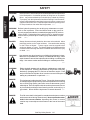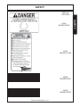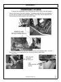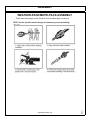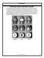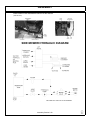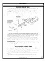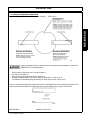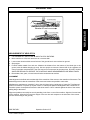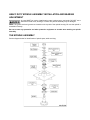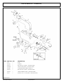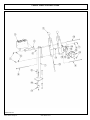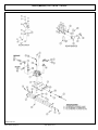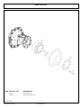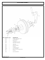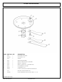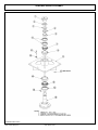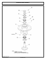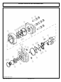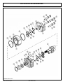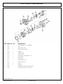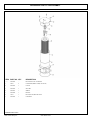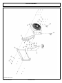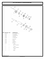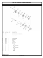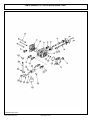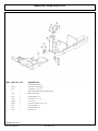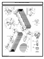
1
SIDE ROTARY
ASSEMBLIES
JD 5065 / 5085 - 5105M
Current as of 06/27/2011
PARTS LISTING WITH
MOUNTING AND OPERATING
INSTRUCTIONS
Tiger Corporation
3301 N. Louise Ave.
Sioux Falls, SD 57107
1-800-843-6849
1-605-336-7900
www.tiger-mowers.com
06010020
TO THE OWNER / OPERATOR / DEALER
All implements with moving parts are potentially hazardous. There is no substitute for a cautious,
safe-minded operator who recognizes the potential hazards and follows reasonable safety practices.
The manufacturer has designed this implement to be used with all its safety equipment properly
attached to minimize the chance of accidents.
BEFORE YOU START!! Read the safety messages on the implement and shown in this manual.
Observe the rules of safety and use common sense!
READ AND UNDERSTAND THIS MANUAL! Non–English speaking operators will need to GET
THE MANUAL TRANSLATED as needed!
Warranty Information: Read and understand the complete Warranty Statement found in this manual. Fill out the
Warranty Registration form in full and return it within 90 days. Make certain the Serial Number of the machine is
recorded on the Warranty Card, and form that you retain.
FORWARD
This manual contains information about many features of the Tiger mowing
and roadside maintenance equipment. Some of these include: Safety precautions,
Assembly instructions, Operations, Maintenance and Parts. This manual will also
assist you in the proper break-in, daily care, and troubleshooting of your new
mower.
We recommend that you read carefully the entire manual before operating the
unit. Also, time spent in becoming fully acquainted with its performance features,
adjustments, and maintenance schedules will be repaid in a long and satisfactory
life of the equipment.
Troubleshooting - Please, before you call, help us to help you!
Please look at the equipment to observe what is happening, then:
• Classify the problem
• Hydraulic, electrical or mechanical - Read the trouble shooting section
• Tractor or Truck chassis - Contact vehicle dealer
• If unable to correct the problem yourself, contact your local Tiger Dealer after
gathering:
• Machine model _______________________
• Serial number ________________________
• Dealer name _________________________
• Detailed information about the problem including results of troubleshooting
Attention Owner / Operator / Dealer: It is your obligation to read, and understand,
the warranty information section located at the back of this manual denoting that the
purchaser understands the safety issues relating to this machine and has received
and will read a copy of this manual.
If at any time, you have a service problem with your Tiger mower, Contact
your local dealer for service and parts needed.
MANUFACTURED BY:
Tiger Corporation
3301 N. Louise Ave.
Sioux Falls, SD 57107
1-800-843-6849
1-605-336-7900
www.tiger-mowers.com
DISTRIBUTED BY:
_____________________
_____________________
1-_____-_____-________
1-_____-_____-________
TABLE OF CONTENTS
SAFETY SECTION_____________________________________
1
ASSEMBLY / MOUNTING SECTION______________________
2
OPERATION SECTION_________________________________
3
MAINTENANCE SECTION______________________________
4
PARTS SECTION______________________________________
5
COMMON PARTS SECTION____________________________
6
WARRANTY INFORMATION_____________________________
7
This symbol means:
CAUTION – YOUR SAFETY IS AT RISK!
When you see this symbol, read and
follow the associated instructions carefully
or personal injury or damage may result.
Tiger is a registered trademark.
SAFETY
SECTION
SAFETY
SAFETY
General Safety Instructions and Practices
A safe and careful operator is the best operator. Safety is of primary importance to the
manufacturer and should be to the owner / operator. Most accidents can be avoided by
being aware of your equipment, your surroundings, and observing certain precautions.
The first section of this manual includes a list of Safety Messages that, if followed, will help
protect the operator and bystanders from injury or death. Read and understand these
Safety Messages before assembling, operating or servicing this mower. This equipment
should only be operated by those persons who have read the Manual, who are responsible
and trained, and who know how to do so safely and responsibly.
The Safety Alert Symbol combined with a Signal Word, as seen below, is used
throughout this manual and on decals which are attached to the equipment. The
Safety Alert Symbol means: “ATTENTION! BECOME ALERT! YOUR SAFETY
IS INVOLVED!” The symbol and signal word are intended to warn the owner /
operator of impending hazards and the degree of possible injury when operating
this equipment.
Practice all usual and customary safe working precautions and
above all -- remember safety is up to YOU! Only YOU can
prevent serious injury or death from unsafe practices.
Indicates an imminently hazardous situation that, if not avoided, WILL result in
DEATH OR VERY SERIOUS INJURY.
Indicates an imminently hazardous situation that, if not avoided, COULD result
in DEATH OR SERIOUS INJURY.
Indicates an imminently hazardous situation that, if not avoided, MAY result in
MINOR INJURY.
IMPORTANT!
NOTE:
Identifies special instructions or procedures that, if not strictly observed, could
result in damage to, or destruction of the machine, attachments or the
enviroment.
Identifies points of particular interest for more efficient or convienient operation
or repair. (SG-1)
READ, UNDERSTAND, and FOLLOW the following Safety Messages.
Serious injury or death may occur unless care is taken to follow the
warnings and instructions stated in the Safety Messages. Always use
good common sense to avoid hazards. (SG-2)
Side Rtry Safety Section 1-2
SAFETY
Si no lee Ingles, pida ayuda a alguien que
si lo lea para que le traduzca las medidas
de seguridad. (SG-3)
DANGER!
Never operate the Tractor or Implement until you have read and
completely understand this Manual, the Tractor Operator’s Manual,
and each of the Safety Messages found in the Manual or on the Tractor
and Implement. Learn how to stop the tractor engine suddenly in an
emergency. Never allow inexperienced or untrained personnel too
operate the Tractor and Implement without supervision. Make sure
the operator has fully read and understood the manuals prior to
operation. (SG-4)
WARNING!
Always maintain the safety decals in good readable condition. If the
decals are missing, damaged, or unreadable, obtain and install replacement decals immediately. (SG-5)
WARNING!
Make certain that the “Slow Moving Vehicle” (SMV) sign is installed in
such a way as to be clearly visible and legible. When transporting the
Equipment use the Tractor flashing warning lights and follow all local traffic
regulations. (SG-6)
WARNING!
Operate this Equipment only with a Tractor equipped with an
approved roll-over-protective system (ROPS). Always wear seat
belts. Serious injury or even death could result from falling off the
tractor--particularly during a turnover when the operator could be
pinned under the ROPS. (SG-7)
WARNING!
Do not modify or alter this Implement. Do not permit anyone to modify
or alter this Implement, any of its components or any Implement
function. (SG-8)
DANGER!
BEFORE leaving the tractor seat, always engage the brake and/or set
the tractor transmission in parking gear, disengage the PTO, stop the
engine, remove the key, and wait for all moving parts to stop. Place the
tractor shift lever into a low range or parking gear to prevent the tractor
from rolling. Never dismount a Tractor that is moving or while the engine
is running. Operate the Tractor controls from the tractor seat only.
Side Rtry Safety Section 1-3
LEA EL
INSTRUCTIVO!
SAFETY
(SG-9)
!
PELIGRO!
SAFETY
DANGER!
Never allow children or other persons to ride on the Tractor or Implement.
Falling off can result in serious injury or death.
SAFETY
(SG-10)
DANGER!
Never allow children to operate or ride on the Tractor or Implement.
(SG-11)
WARNING!
Do not mount the Tractor while the tractor is moving. Mount the Tractor
only when the Tractor and all moving parts are completely stopped.
(SG-12)
DANGER!
Start tractor only when properly seated in the Tractor seat. Starting a
tractor in gear can result in injury or death. Read the Tractor operators
manual for proper starting instructions. (SG-13)
DANGER!
Never work under the Implement, the framework, or any lifted component unless the Implement is securely supported or blocked up to
prevent sudden or inadvertent falling which could cause serious injury
or even death. (SG-14)
DANGER!
Do not operate this Equipment with hydraulic oil leaking. Oil is
expensive and its presence could present a hazard. Do not check for
leaks with your hand! Use a piece of heavy paper or cardboard. Highpressure oil streams from breaks in the line could penetrate the skin
and cause tissue damage including gangrene. If oil does penetrate the
skin, have the injury treated immediately by a physician knowledgeable and skilled in this procedure. (SG-15)
Side Rtry Safety Section 1-4
SAFETY
The operator and all support personnel should wear hard hats,
safety shoes, safety glasses, and proper hearing protection at all
times for protection from injury including injury from items thrown by
the equipment.
(SG-16)
CAUTION!
PROLONGED EXPOSURE TO LOUD NOISE MAY CAUSE PERMANENT HEARING LOSS! Tractors with or without an Implement
attached can often be noisy enough to cause permanent hearing
loss. We recommend that you always wear hearing protection if the
noise in the Operator’s position exceeds 80db. Noise over 85db
over an extended period of time will cause severe hearing loss.
Noise over 90db adjacent to the Operator over an extended period of
time will cause permanent or total hearing loss. Note: Hearing loss
from loud noise [from tractors, chain saws, radios, and other such
sources close to the ear] is cumulative over a lifetime without hope
of natural recovery. (SG-I7)
Transport only at safe speeds. Serious accidents and injuries can
result from operating this equipment at unsafe speeds. Understand
the Tractor and Implement and how it handles before transporting
on streets and highways. Make sure the Tractor steering and brakes
are in good condition and operate properly.
SAFETY
WARNING!
WARNING!
Before transporting the Tractor and Implement, determine the safe
transport speeds for you and the equipment. Make sure you abide by
the following rules:
1. Test the tractor at a slow speed and increase the speed slowly.
Apply the Brakes smoothly to determine the stopping
characteristics of the Tractor and Implement.
As you increase the speed of the Tractor the stopping distance
increases. Determine the maximum safe transport speed for
you and this Equipment.
2. Test the equipment at a slow speed in turns. Increase the speed
through the turn only after you determine that it is safe to operate at a higher speed. Use extreme care and reduce your speed
when turning sharply to prevent the tractor and implement from
turning over. Determine the maximum safe turning speed for
you and this equipment before operating on roads or uneven
ground.
Only transport the Tractor and Implement at the speeds that you
have determined are safe and which allow you to properly control the equipment.
3. Be aware of the operating conditions. Do not operate the Tractor
with weak or faulty brakes. When operating down a hill or on wet or
rain slick roads, the braking distance increases: use extreme care
and reduce your speed. When operating in traffic always use the
Tractor’s flashing warning lights and reduce your speed. Be aware of
traffic around you andwatch out for the other guy. (SG-19)
Side Rtry Safety Section 1-5
SAFETY
SAFETY
WARNING!
Never attempt to lubricate, adjust, or remove material from the
Implement while it is in motion or while tractor engine is running. Make
sure the tractor engine is off before working on the Implement.
(SG-20)
WARNING!
Periodically inspect all moving parts for wear and replace when
necessary with authorized service parts. Look for loose fasteners,
worn or broken parts, and leaky or loose fittings. Make sure all pins
have cotter pins and washers. Serious injury may occur from not
maintaining this machine in good working order. (SG-21)
WARNING!
Always read carefully and comply fully with the manufacturers instructions when handling oil, solvents, cleansers, and any other chemical
agent. (SG-22)
DANGER!
Never run the tractor engine in a closed building or without adequate
ventilation. The exhaust fumes can be hazardous to your health.
(SG-23)
DANGER!
KEEP AWAY FROM ROTATING ELEMENTS to prevent entanglement
and possible serious injury or death.
(SG-24)
DANGER!
Never allow children to play on or around Tractor or Implement. Children
can slip or fall off the Equipment and be injured or killed. Children can
cause the Implement to shift or fall crushing themselves or others. (SG-25)
DANGER!
DO NOT allow any person under a folded wing unless wing is securely
locked up or supported. DO NOT approach the Implement unless the
Tractor is turned off and all motion has ceased. Never work under the
frame work, or any lifted component unless the implement is securely
supported or blocked up. A sudden or inadvertent fall by any of these
components could cause serious injury or even death. (STI-3)
Side Rtry Safety Section 1-6
SAFETY
CAUTION!
On a fully-assembled unit, do not remove the Wing Retaining Strap
until hoses are attached to the tractor and the Wing Cylinders are
filled with oil. Lower the Wings slowly and carefully. Keep bystanders away during operations. (STI-5)
NEVER use drugs or alcohol immediately before or while operating the
Tractor and Implement. Drugs and alcohol will affect an operator’s
alertness and coordination and therefore affect the operator’s ability to
operate the equipment safely. Before operating the Tractor or Implement, an operator on prescription or over-the-counter medication must
consult a medical professional regarding any side effects of the medication that would hinder their ability to operate the Equipment safely.
NEVER knowingly allow anyone to operate this equipment when their
alertness or coordination is impaired. Serious injury or death to the
operator or others could result if the operator is under the influence of
drugs or alcohol. (SG-27)
DANGER!
Operate the Tractor and/or Implement controls only while properly seated
in the Tractor seat with the seat belt securely fastened around you.
Inadvertent movement of the Tractor or Implement may cause serious
injury or death. (SG-29)
WARNING!
Mow only in conditions where you have clear visibility in daylight or with
adequate artificial lighting. Never mow in darkness or foggy conditions
where you cannot clearly see at least 100 yards in front and to the sides of
the tractor and mower. Make sure that you can clearly see and identify
passersby, steep slopes, ditches, drop-offs, overhead obstructions, power
lines, debris and foreign objects. If you are unable to clearly see this type
of items discontinue mowing.
(SGM-1)
DANGER!
There are obvious and hidden potential hazards in the operation of this
Mower. REMEMBER! This machine is often operated in heavy brush
and in heavy weeds. The Blades of this Mower can throw objects if
shields are not properly installed and maintained. Serious injury or
even death may occur unless care is taken to insure the safety of the
operator, bystanders, or passersby in the area. Do not operate this
machine with anyone in the immediate area. Stop mowing if anyone
is within 100 yards of mower. (SGM-2)
DANGER!
All Safety Shields, Guards and Safety devices including
(but not limited to) - the Deflectors, Chain Guards, Steel
Guards, Gearbox Shields, PTO integral shields , and
Retractable Door Shields should be used and maintained in good working condition. All safety devices
should be inspected carefully at least daily for missing
or broken components. Missing, broken, or worn items
must be replaced at once to reduce the possibility of
injury or death from thrown objects, entanglement, or
blade contact. (SGM-3)
Side Rtry Safety Section 1-7
SAFETY
DANGER!
SAFETY
SAFETY
DANGER!
The rotating parts of this machine have been designed and tested for
rugged use. However, the blades could fail upon impact with heavy,
solid objects such as metal guard rails and concrete structures. Such
impact could cause the broken objects to be thrown outward at very
high velocities. To reduce the possibility of property damage, serious
injury, or even death, never allow the cutting blades to contact such
obstacles. (SGM-4)
WARNING!
Extreme care should be taken when operating near loose objects such
as gravel, rocks, wire, and other debris. Inspect the area before
mowing. Foreign objects should be removed from the site to prevent
machine damage and/or bodily injury or even death. Any objects that
cannot be removed must be clearly marked and carefully avoided by
the operator. Stop mowing immediately if blades strike a foreign
object. Repair all damage and make certain rotor or blade carrier is
balanced before resuming mowing. (SGM-5)
WARNING!
Many varied objects, such as wire, cable, rope, or chains, can become
entangled in the operating parts of the mower head. These items could
then swing outside the housing at greater velocities than the blades. Such
a situation is extremely hazardous and could result in serious injury or
even death. Inspect the cutting area for such objects before mowing.
Remove any like object from the site. Never allow the cutting blades to
contact such items. (SGM-6)
WARNING!
Mow at the speed that you can safely operate and control the tractor and
mower. Safe mowing speed depends on terrain condition and grass type,
density, and height of cut. Normal ground speed range is from 0 to 5 mph.
Use slow mowing speeds when operating on or near steep slopes,
ditches, drop-offs, overhead obstructions, power lines, or when debris and
foreign objects are to be avoided. (SGM-7)
WARNING!
Avoid mowing in reverse direction when possible. Check to make sure there
are no persons behind the mower and use extreme care when mowing in
reverse. Mow only at a slow ground speed where you can safely operate and
control the tractor and mower. Never mow an area that you have not
inspected and removed debris or foreign material. (SGM-8)
WARNING!
Do not put hands or feet under mower decks. Blade Contact can result
serious injury or even death. Stay away until all motion has stopped and
the decks are securely blocked up.
(SGM-9)
DANGER!
Replace bent or broken blade with new blades. NEVER ATTEMPT TO
STRAIGHTEN OR WELD ON BLADES SINCE THIS WILL LIKELY
CRACK OR OTHERWISE DAMAGE THE BLADE WITH SUBSEQUENT FAILURE AND POSSIBLE SERIOUS INJURY FROM THROWN
BLADES. (SGM-10)
WARNING!
Do not mow with two machines in the same area except with Cab tractors
with the windows closed. (SGM-11)
Side Rtry Safety Section 1-8
SAFETY
DANGER!
NOTE: Where there are grass and weeds high enough to hide debris
that could be struck by the blades, the area should be: inspected and large debris removed, mowed at an intermediate
height, inspected closely with any remaining debris removed,
and mowed again at desired final height. (SBM-1)
WARNING!
Each Rear Wheel must have a minimum of 1,000 pounds contact with
the surface to prevent lateral instability and possible tip-over which
could result in serious bodily injury or even death. Widen the wheel
tread and add weights if needed. Refer to the mounting instructions
or call Customer Service if you need assistance with Couterweight
Procedure. (SFL-3)
WARNING!
Do not operate Mower if excessive vibration exists. Shut down PTO
and the Tractor engine. Inspect the Mower to determine the source
of the vibration. If Mower blades are missing or damaged replace
them immediately. Do not operate the mower until the blades have
been replaced and the Mower operates smoothly. Operating the
Mower with excessive vibration can result in component failure and
broken objects to be thrown outward at very high velocities. To reduce
the possibility of property damage, serious injury, or even death, never
allow the Mower to be operated with blades missing. (SFL-4)
WARNING!
Do not let the Blades turn when the Mower Deck is raised for any
reason, including clearance or for turning. Raising the Mower
deck exposes the Cutting Blades which creates a potentially
serious hazard and could cause serious injury or even death from
objects thrown from the Blades. (SRM-7)
DANGER!
Use extreme caution when raising the Mower head. Stop the Blades
from turning when the Mower Head is raised and passersby are within
100 yards. Raising the Mower head exposes the Cutting Blades
which creates a potentially serious hazard and can cause serious
injury by objects thrown from the Blades or by contact with the Blades.
(SBM-2)
Side Rtry Safety Section 1-9
SAFETY
Rotary Mowers are capable under adverse conditions of throwing
objects for great distances
(100 yards or more) and causing
serious injury or death. Follow safety messages carefully.
STOP MOWING IF PASSERSBY ARE WITHIN 100 YARDS UNLESS:
-Front and Rear Deflectors are installed and in good,
working condition;
-Mower Head is running close to and parallel to the ground
without exposed Blades;
-Passersby are outside the existing thrown-object zone;
-All areas have been thoroughly inspected and all foreign
material such as rocks, cans, glass, and general debris
has been removed.
SAFETY
SAFETY
WARNING!
WARNING!
Never leave the Tractor and Implement unattended while the Implement is
in the lifted position. Accidental operation of lifting lever or a hydraulic
failure may cause sudden drop of unit with injury or death by crushing.
To properly park the implement when disconnecting it from the tractor,
lower the stand and put the retaining pin securely in place, or put a secure
support under the A-Frame. Lower the implement carefully to the ground.
Do not put hands or feet under lifted components. (S3PT-1)
Relieve hydraulic pressure prior to doing any maintenance or repair
work on the Implement. Place the Mower Head on the ground or
securely supported on blocks or stands, disengage the PTO, and turn
off the engine. Push and pull the control Levers or Joystick several
times to relieve pressure prior to starting any maintenance or repair
work.
(SBM-6)
DANGER!
Always disconnect the wire leads from the mower valve solenoid before
performing service on the Tractor or Mower. Use caution when working
on the Tractor or Mower. Tractor engine must be stopped before
working on Mower or Tractor. The Mower Blades could inadvertently be
turned on without warning and cause immediate dismemberment, injury
or death. (SBM-12)
WARNING!
Use extreme care when lowering or unfolding the implement’s wings.
Make sure no bystanders are close by or underneath the wings. Allow
ample clearance around the implement when folding or unfolding the
wings. Use extreme caution around buildings or overhead power lines.
(S3PT5)
WARNING!
Relieve hydraulic pressure prior to doing any maintenance or repair work
on the Implement. Place the Implement on the ground or securely
blocked up, disengage the PTO, and turn off the tractor engine. Push
and pull the Remote Cylinder lever in and out several times prior to
starting any maintenance or repair work. (S3PT-9)
DANGER!
This Implement is wider than the Tractor. Be careful when operating
or transporting this equipment to prevent the Implement from running
into or striking sign posts, guard rails, concrete abutments or other
solid objects. Such an impact could cause the Implement and Tractor
to pivot violently resulting in loss of steering control, serious injury, or
even death. Never allow the Implement to contact obstacles. (S3PT12)
DANGER!
The flail cutter shaft is designed for standard rotation(same rotation
as the tractor wheel during forward travel). Never operate the cutter
shaft in the reverse rotation. Operating this mower in reverse
rotation may cause objects to be thrown out the front of the mower
head.
Side Rtry Safety Section 1-10
SAFETY
The rotating parts of this machine continue to rotate even after the Tractor
has been turned off. The operator should remain in his seat for 60
seconds after the brake has been set, the PTO disengaged, the tractor
turned off, and all evidence of rotation has ceased. (SBM-5)
“Wait a minute...Save a life!”
WARNING!
Engine Exhaust, some of its constituents, and certain components
contain or emit chemicals known to the state of California to cause
cancer and birth or other reproductive harm.
WARNING!
Battery post, terminals and related accessories contain lean and lead
compounds, chemicals known to the state of California to cause cancer
and birth or other reproductive harm. Wash hands after handling!
Tiger mowers use balanced and matched system components for blade carriers, blades, cutter-shafts, knives, knife hangers, rollers, drive-train components and bearings. These parts are made and tested to Tiger specifications. Non-genuine
“will fit” parts do not consistently meet these specifications. The use of “will fit” parts may reduce mower performance,
void mower warranties and present a safety hazard. Use genuine Tiger mower parts for economy and safety.
SEE YOUR
DEALER
In addition to the design and configuration of this Implement, including Safety Signs and Safety Equipment, hazard
control and accident prevention are dependent upon the awareness, concern, prudence, and proper training of
personnel involved in the operation, transport, maintenance, and storage of the machine. Refer also to Safety
Messages and operation instruction in each of the appropriate sections of the Tractor and Equipment Manuals.
Pay close attention to the Safety Signs affixed to the Tractor and Equipment. (SG-18)
Side Rtry Safety Section 1-11
SAFETY
WARNING!
SAFETY
SAFETY
Side Rtry Safety Section 1-12
SAFETY
PART NO.
QTY.
DESCRIPTION
1
22839
1
INSTRUCT
Don Not Lubricate With Automatic Grease Gun
2
22840
1
WARNING
Foreign Objects Contacted
3
24028
1
WARNING
Inspect Rear Flap
4
31522
1
LOGO
TIGER MOWERS
5
31523
3
LOGO
TIGER MOWERS
6
42350
1
DANGER
Cuttershaft Direction
7
33743
1
INSTRUCT
Mowing Safet Tips
8
42399
1
REFLECT
Red Reflector
9
42400
1
REFLECT
Amber Reflector
10
6T3217
1
DANGER
Keep Hands and Feet Clear
11
6T3219
1
WARNING
Read Operators and Maintenance Manuals
12
6T3220
1
INTRUCT
Lubricate Pump, Driveshaft Daily
13
6T3221
1
CAUTION
Lubricate Spindle When Mower and Tractor Off
14
6T3222
1
INSTRUCT
Engine will not start when mower is engaged
15
1059
1
INSTRUCT
Mower Positions
16
6T3224
1
DANGER
Stay Clear, Discharge Opening
17
6T3230
1
WARNING
Don't Operate with Bystanders in Area
18
6T3233
1
CAUTION
DONOT Start or Run with Valves closed
19
6T3234
1
CAUTION
Check Crankshaft Adapter Daily
20
6T3236
1
LOGO
Made In USA
21
6T3243
1
WARNING
Replace Bolts and Locknut if damaged
22
6T3249A
1
INSTRUCT
Grease Inst. Cuttershaft Bearing
23
6T3261
1
INSTRUCT
Grease Inst. Ground Roller Bearing
24
TB1011
1
WARNING
Do Not Work Mower with Safety Shiel Removed
25
02962764
1
WARNING
Pinch Point
26
02965262
1
WARNING
Hydraulic Hose Repair
27
02967827
1
DANGER
Multi Warn Messages
28
34852
1
INSTRUCT
Hydraulic Specifications
29
00756059
1
WARNING
Check Hydraulic Hose with Cardboard
Side Rtry Safety Section 1-13
SAFETY
ITEM
SAFETY
PART NO.
LOCATION
SAFETY
22839
MOWER DECK
22840
INSIDE OF CAB
24028
MOWER DECK
10"X5.5"
31522
MOWER DECK
18.25"X10" 31523
HYDRAULIC TANK
Side Rtry Safety Section 1-14
SAFETY
PART NO.
LOCATION
33743
INSIDE OF CAB
5
42399
MOWER DECK
42400
MOWER DECK
Side Rtry Safety Section 1-15
SAFETY
42350
MOWER DECK
SAFETY
SAFETY
PART NO.
LOCATION
6T3217
MOWER DECK
6T3219
INSIDE OF CAB
6T3220
FRONT PUMP MOUNT
6T3221
INSIDE OF CAB
29-6T3221
Side Rtry Safety Section 1-16
SAFETY
PART NO.
LOCATION
6T3234
INSIDE OF CAB
6T3236
MOWER DECK
6T3243
INSIDE OF CAB
Side Rtry Safety Section 1-17
SAFETY
6T3233
INSIDE OF CAB
SAFETY
SAFETY
PART NO.
LOCATION
6T3233
HYDRAULIC TANK
6T3234
INSIDE OF CAB
6T3236
MOWER DECK
HYDRAULIC TANK
6T3243
INSIDE OF CAB
16
Side Rtry Safety Section 1-18
SAFETY
PART NO.
LOCATION
6T3261
MOWER DECK
TB1011
MOWER DECK
02962764
MOWER DECK
DRAFT BEAM
Side Rtry Safety Section 1-19
SAFETY
6T3249A
MOWER DECK
SAFETY
SAFETY
PART NO.
LOCATION
02965262
DRAFT BEAM
02967827
CAB FENDER
Side Rtry Safety Section 1-20
SAFETY
SAFETY
34852
HYDRAULIC TANK
00756059
MOWER DECK
Side Rtry Safety Section 1-21
SAFETY
SAFETY
ITEM
PART NO.
QTY.
DESCRIPTION
1
50023
00776031
33997
AVAIL
1
1
*
*
*
AVAIL
1
1
1
4
MANUAL CANISTER COMPLETE
Round Manual Canister
Decal, Sheet, Manual Canister
Decal
Decal
Decal
Specification Product Manual
EMI Safety Manual
Front Adhesive Pad
Rear Adhesive Pad
Zip Tie 14" Long
2
3
4
5
6
7
8
9
*
33753
34296
34297
6T1823
NOTE:
The manual canister can be bolted, zip tied or adhered to a variety of surfaces. Locate a protected area within
the view of the operator. Then select an installation method and attach the canister. CAUTION-AVOID DRILLING HOLES INTO UNKNOWN AREAS, wires and other parts may be located behind these areas. When
adhering the canister to a surface, thoroughly clean that surface before installing the canister.
Side Rtry Safety Section 1-22
SAFETY
FEDERAL LAWS AND REGULATIONS
This section is intended to explain in broad terms the concept and effect of federal laws and regulations concerning
employer and employee equipment operators. This section is not intended as a legal interpretation of the law and
should not be considered as such.
This Act Seeks:
“...to assure so far as possible every working man and woman in the nation safe and healthful
working conditions and to preserve our human resources...”
DUTIES
Sec. 5 (a) Each employer(1) shall furnish to each of his employees employment and a place of employment which are free
from recognized hazards that are causing or are likely to cause death or serious physical harm to
his employees;
(2) shall comply with occupational safety and health standards promulgated under this Act.
(b) Each employee shall comply with occupational safety and health standards and all rules,
regulations and orders issued pursuant to this Act which are applicable to his own actions and
conduct.
OSHA Regulations
OSHA regulations state in part: “At the time of initial assignment and at least annually thereafter,
the employer shall instruct every employee in the safe operation and servicing of all equipment with
which the employee is, or will be involved.”
Employer Responsibilities:
To ensure employee safety during Truck and Implement operation, it is the employer’s responsibility to:
1. Train the employee in the proper and safe operation of the Truck and Implement.
2. Require that the employee read and fully understand the Truck and Implement Operator’s manual.
3. Permit only qualified and properly trained employees to operate the Truck and Implement.
4. Maintain the Truck and Implement in a safe operational condition and maintain all shields and guards on the
equipment.
5. Ensure the Truck is equipped with functional seat belts and require that the employee operator securely
fasten the safety belts at all times.
6. Forbid the employee operator to carry additional riders on the Truck.
7. Provide the required tools to maintain the Truck and Implement in a good safe working condition and provide
the necessary support devices to secure the equipment safely while performing repairs and service.
Child Labor Under 16 Years of Age
Some regulations specify that no one under the age of 16 may operate power machinery. It is your responsibility
to know what these regulations are in your own area or situation. (Refer to U.S. Dept. of Labor, Employment
Standard Administration, Wage & Home Division, Child Labor Bulletin #102.)
Side Rtry Safety Section 1-23
SAFETY
Employer-Employee Operator Regulations
U.S. Public Law 91-596 (The Williams-Steiger Occupational and Health Act of 1970) OSHA
SAFETY
SAFETY
Side Rtry Safety Section 1-24
JD5XX5M - TM
ASSEMBLY SECTION
Assembly Section 2-1
ASSEMBLY
Before attempting to mount your Tiger mower, it is
important to read an understand all of the Safety Messages in
the Safety section of this manual.
Check complete shipment list against the packing list to make sure there are no
shortages. Make certain the tractor model is the appropriate one for the mower
received!
Always use a floor jack, hoist or fork lift to lift and raise heavy parts.
Read and understand the entire assembly section instructions before attempting
to mount your Tiger mower. Refer to the parts section of this manual for detailed
illustrations to locate all parts. (ASM-C-0001)
TRACTOR PREPARATION
A.
Remove right and left hand steps.
B.
Disconnect battery cables from both batteries.
C.
Remove engine side panels, or raise hood to access front pulley.
D.
Remove plugs from tractor casting where main frame and pump mount will be attached.
E.
Remove any front weights and weight supports.
F.
Raise the tractor onto jack-stands and remove the right and left rear wheels.
(ASM-JD-0001)
CRANKSHAFT ADAPTER
For JD5065M and 5075M tractors, remove the four capscrews from the crankshaft
pulley. Then install the crankshaft adapter and spacer to the pulley with the capscrews and
lockwashers as shown in the Parts Section.
For JD5085M - JD5105M tractors, install the John Deere kit LVB24989 and follow the
instructions. (ASM-JD-0085)
Assembly Section 2-2
ASSEMBLY
CRANKSHAFT ACCESS
To access the crankshaft of the JD5065M and 5085-105M, a hole will need to
be cut in the front of the tractor casting. The battery plate will need to be raised to
cut the hole and attach the crankshaft adapter. To do this, remove and save the
bolts holding the battery plate to the tractor frame.
After the bolts have been removed, use a pry bar to raise the battery plate. Once the
plate is raised, use an appropriate block to keep the battery plate raised.
(ASM-JD-0086)
USE PRY BAR
TO RAISE
BATTERY LTE
USE
APPROPRIATE
BLOCK
Assembly Section 2-3
ASSEMBLY
CRANKSHAFT ACCESS (continued)
Find the center punched marking on the front end of the tractor(shown below), and
use it as a guide for cutting. Use a 1-3/4” hole saw to cut a hole for the driveshaft. Once
the hole is cut you will be able to look through the hole and see the driveshaft cover.
The driveshaft cover is held on by two bolts. To remove these bolts take off the panel
covering the fan. Then you will have access to the bolts on the driveshaft cover.
The battery plate will need to stay elevated for the crankshaft adapter to be installed on the
crankshaft pulley. Tilt the crankshaft adapter and slide it into place.
Before inserting the driveshaft into the crankshaft adapter, apply Anti-Seize lubricant to
the splines of the driveshaft. Re-apply Anti-Seize once a year after that.
After the crankshaft adapter is installed & torqued, remove blocks and re-install bolts
that were removed to prop up the battery plate. (ASM-JD-0097)
Assembly Section 2-4
ASSEMBLY
DRIVESHAFT & FRONT PUMP MOUNTING
Thread the pump drive shaft into the crankshaft adapter.
Slide splined drive shaft coupler onto the pump drive shaft. Install the pump onto the
mounting bracket. NOTE: the pump is offset to one direction, the pump should be installed
with the offset side on top. Install hardware for securing pump to the pump mount, DO NOT
tighten.
Install pump and align so that splined coupling can be moved (FREE PLAY) back and
forth by hand. Rotate coupler and check free play every 1/4 turn. Tighten pump mounting
bolts in succession rechecking for spline coupling free play. Remove the pump mounting
bracket bolts one at a time and apply a thread locking agent. Tighten these bolts in
succession, again checking for free play in the drive shaft. After all bolts are torqued, the end
play on the drive shaft should be 1/16” to 1/8”, and coupler should move freely with hand
pressure. If end play is less than 1/16”, grind the end of the shaft to achieve the proper end
play. If there is more than 1/4” of end play, return the shaft with specifications for a longer
shaft.
CAUTION: DO NOT START THE TRACTOR UNTIL ALL HOSES ARE ATTACHED,
TANK IS FILLED WITH PROPER OIL AND BALL VALVES ARE OPEN! STARTING AT
THIS TIME WILL CAUSE SERIOUS DAMAGE TO THE PUMP.(ASM-C-0091)
ADJUSTING REAR WHEELS
Raise rear of tractor onto jack-stands. Follow the instructions in the tractor owners
manual for adjusting tires and rims. The back wheels MUST be adjusted to the widest
setting. NOTE: This may require switching the wheels to opposite sides of tractor. Also take
note of any width restrictions when transporting by trailer. (For ease of installation, it is best to
leave the rear wheels removed during installation of the mower.) (ASM-B-0001)
Assembly Section 2-5
ASSEMBLY
CABLE CONTROL LEVER STAND
Place the cable control bracket on the floor so that the bracket is 2-1/2” from the side
edge of the door, and 4-3/8” in front of the rear edge of the door. See images below. Be
sure that the location of the stand will allow the operation of all control levers in the tractor
and that the door will not strike the stand when shut. Before drilling double check location
of the stand for proper placement of holes. Make sure that all cables and wires are clear
of the area before drilling holes to mount the stand. Drill 3 holes to match control bracket
as shown below and secure with capscrews and nylock nuts noted in parts section..
The rubber boot under the rear window can be cut in a cross hair pattern and if
necessary the bottom cut through to allow it to slip over the cables and back into position.
These cables will be routed to the lift valve mounted on the valve mounting plate, and
should not have any sharp bends or kinks in them. Secure cables with zip ties and apply
RTV sealer in and around individual cables, inside and outside of the cab for a water tight
seal. Do not allow excess cable to hang unsecured on the outside of the cab. (ASM-JD0087).
Assembly Section 2-6
ASSEMBLY
SWITCH BOX WIRING
Route the green wires and the red wire (with the 10amp fuse) from the switchbox
to the front console panel. Refer to the parts section for wiring diagram to hook up
the switch box. Cover the wires from the switch box with plastic wire wrap provided.
Remove the console panel under the steering wheel to access wires. Locate the
neutral safety brown colored wire. Use a test light or meter to verify this wire is the
neutral safety wire. There are three brown wires. Cut the brown neutral safety wire
and connect the green wires from the switch box as shown in the wiring diagram.
Run the white and black wire to the solenoid valve. Route the wires through the
back window with the cable control wires. Use the rubber grommet in the window to
protect the wire, and route the wire out of the cab down to the 1/4” hydraulic hoses.
Follow the hydraulic hoses through the wheel well to the front of the tractor.
Route the Red 14ga wire, keyed hot, from the auxillary plug to the signal post of
the continuous duty solenoid. NOTE: Be certain that the power taken for the
switch box is “HOT” only when the tractor ignition is “ON”.
The black wire from the switchbox should be routed to the auxilary plug.
The wires from the switch box are longer than needed and should carefully cut and
spliced as required. Zip ties should be used to secure the wires to the tractor
framework and hoses to eliminate vibation and rubbing. (ASM-JD-0055)
Assembly Section 2-7
ASSEMBLY
WEATHER-PACK/METRI-PACK ASSEMBLY
These instructions apply to both Weather-Pack and Metri-pack connectors.
NOTE: Use the specific tool for the type of connector you are assembling.
(ASM-C-0009)
Assembly Section 2-8
ASSEMBLY
VALVE MOUNTING
Attach the rear valve mounting bracket to the fender of the tractor by removing the
two rear bolts on the left fender and the two rear bolts on the right fender. See
illustration below. Drill the square holes in the fenders to accept 3/8” capscrews. Use
the hardware noted in the parts section to attach the valve mounting bracket to the
tractor.
Next, attach the valve mounting plate to the mounting bracket. Align the holes on
the plate to the holes on the bracket. Use the hardware shown in the parts section to
attach the plate to the valve mounting bracket. Finally, place the valve on the valve
mounting plate as shown in the parts section. Align the holes on the valve assembly
to the holes on the plate. Use the hardware provided to secure the valve to the plate.
Refer to the parts section for the placement of the valve and the hardware used.
Please handle the lift valve with care. It is extremely heavy and contains small
parts. (ASM-JD-0065)
Assembly Section 2-9
ASSEMBLY
PRESSURE LINE INSTALLATION
The hydraulic pressure line will be plumbed into the tractors power beyond port.
Locate the power beyond port on the upper right side of the tractor rear remotes,
remove the plug (refer to the illustration below and the Parts Section). After the plug
is removed, connect the adapter and route the hose from the adapter to the lift valve,
as shown in the Parts Section. (ASM-JD-0089)
RETURN LINE INSTALLATION
The return line will be plumbed into the front of the Branch Tee, as shown in
previous illustration, which will be assembled into the adapter located below the
tractors’ power beyond port. Remove the elbow or plug from the rear remotes and
replace it with the supplied Branch Tee. Connect the line from the Mid-mount valve to
the Branch Tee. If your tractor does not have a Mid-mount valve, then install the
supplied cap on the back side of the Branch Tee. Plumb the return line from the front
ot the Branch Tee to the adapter on the lift valve. (ASM-JD-0090)
Assembly Section 2-10
ASSEMBLY
MANUAL LIFT VALVE PORTS
(ASM-C-0057)
MANUAL SWITCH BOX MOUNTING
The switch box is to be secured to the operators side of the control handles, or valve
stand. Refer to the parts section for assembly and components needed.
(ASM-C-0071)
Assembly Section 2-11
ASSEMBLY
*NOTE ON HUSCO CONTROL VALVES*
Manual, cable controlled (Husco control valve) boom mowers require check valves
with integral restricting orifice (#06502036) installed in the control valve work ports that
are connected to the gland ends of the main and secondary boom cylinders. This check
valve allows oil to free flow into the gland end of the main and secondary boom cylinders,
but restricts flow out of the cylinder, thereby providing proper boom control. This check
valve, #06502036(Vendor #1968R-.063) is similar in appearance to hose adapter #33271
and Adapter #34396, with.06 orifice. These components can be identified as follows, and
are to be installed per parts section for the lift valve. (ASM-HUSCO-0001)
Assembly Section 2-12
ASSEMBLY
HOSE AND WIRE ROUTING
Attach two clamps to the right rear wheel well for proper hose/wire routing. Drill
one hole for each clamp. Use the lower rear corner of the wheel well as an origin for
measuring. The holes should be 10mm or 3/8” reamed to accept 3/8” hardware.
Measure along the back edge of the wheel well 6” from the origin. Use a square to
measure 2-½” up, from the last mark. Refer to the image below to see the first hole.
The second hole should run parallel to the bottom edge of the wheel well. Mark
the hole 22” from the origin and 3-½” from the bottom edge. Use the images below
for reference.
NOTE: DO NOT CUT INTO TUBES / HOSES / WIRES WHEN DRILLING
THROUGH METAL OR PLASTIC!. (ASM-JD-0068)
Place as many hoses in the clamp that will fit without compromising pressure. Then
secure the (2) HOSE CLAMP (06520013) to the holes drilled with (1 EACH)
CAPSCREW,3/8 X 1 NC (21630) and (1 EACH) NYLOCK NUT,3/8 NC (21627). The
hoses that don’t fit into the clamp are to be secured to the others with zip-ties. For
protection of hoses in contact with metal edges, wrap hoses with spit hose sections
and fasten with hose clamps or zip ties as needed.
Assembly Section 2-13
ASSEMBLY
FENDER CUT FOR WHEEL WELL TANK
A notch will have to be cut into the left rear fender to allow room for the hydraulic
tank filler neck. The notch should start at 2 inches from the rear corner of the fender and
create a 1 inch deep arc that is 5 inches long. Trim lock should be used on the sharp
edges.. (ASM-JD-0092)
HOSE ROUTING
It is important to route the hoses as shown below from the brake valve, behind the
Assembly Section 2-14
ASSEMBLY
mast, and to the flail mowers. The hoses may get into the front and/or rear tires if not
properly routed and clamped. (ASM-C-0061)
FILLING HYDRAULIC RESERVOIR
Refer to the maintenance section for filling specifications and hydraulic oil
Assembly Section 2-15
ASSEMBLY
requirements.
(ASM-C-0004hydro resrv)
WHEEL SPACER WITH WHEEL WELL TANK
When the left wheel is off, a spacer kit is needed with the wheel well tank (part#
06200637.) Attach the spacer to the left wheel portion of the axle with the hardware
provided. When you are ready to re-attach the left wheel, the wheel goes on first then
the reinforcement ring and finally the hardware provided.
(ASM-JD-0070)
INSTALLING O-RING FITTINGS
Installing straight, 45º and 90º O-rings requires that the O-ring and washer be up against the
swivel body. Insert the swivel and turn in until the swivel is pointed in the desired direction and Oring contact is made. Hold swivel in set direction with a wrench and turn the O-ring nut away
from the swivel body and carefully tighten.
(ASM-C-0056)
INSTALLING NATIONAL PIPE FITTINGS
Whenever installing a pipe fitting, wrap the threads clockwise (looking at the end) with
teflon tape. In this way, the tape will be tightened when installed. NOTE: It is not
necessary to tape O-ring fittings, or those installed in swivels. (ASM-C-0088)
Assembly Section 2-16
ASSEMBLY
GENERAL HOSE INSTALLATION
Refer to the parts section for detailed information about hoses and fittings for this
application. (ASM-C-0011)
HOSE COVERING
Secure hoses together with zip ties wherever loose. Wrap the hoses between the
swivel and main boom with the hose cover provided. Wrap the hoses between the main
boom and secondary boom with the hose cover provided. Where hoses may contact the
frame or other edges, wrap with split hose and secure with hose clamps or zip ties.
On non cab units, the pressure and return hoses from the control valve will also need
to be routed inside the protective clear hose wrap. Cover the valve, valve fittings with the
yellow hose cover and secure with black string provided.
(ASM-C-0058)
SOLENOID BRAKE VALVE
Install a solenoid valve on the mounting bracket with the supplied hardware as shown
in the Parts Section in this manual. While installing the fittings to the brake valve, the
electical coil on the spool may have to be removed to make room. When reinstalling the
coil, it is important to use no more than 5 ft. lbs. (or 60in. lbs.) torque. WARNING: OVER
TORQUE TO THE COIL WILL RESULT IN HYDRAULIC FAILURE OF SPOOL. (ASM-C0025)
TEMPERATURE GAUGE MOUNTING (OPTIONAL)
Mount the temperature gauge where it is clearly visible to the operator. Attach the
green (-) wire from the negative post on the gauge to a grounded bolt on the tractor
frame. Remove paint if needed to make a good ground. Remove the pipe plug from the
side of the hydraulic reservoir and install the temperature sensor using thread sealing
tape. Run the white wire from the (s) sensor post of the gauge to the temperature sensor
on the hydraulic reservoir tank. (ASM-C-0051)
MAIN FRAME INSTALLATION
With an overhead hoist and / or jack-stands, raise one side of the frame up to the
correctly matching mounting holes. Install capscrews and all other hardware as shown in
main frame parts section to secure the sides of the main frame to the tractor casting, DO
NOT tighten at this time. Remove the capscrews one at a time and apply a thread locking
agent. Reinsert the capscrews and tighten / torque to values noted in the torque chart
located in the maintenance section of this manual. (ASM-C-0003)
AXLE BRACE MOUNTING
Position the right axle brace under the tractor right hand side. Raise the brace up to
the matching mounting holes in the main fame and rear axle housing. Note the right side
brace is installed on outside edge of the main frame and the left side brace is installed on
the inside edge of the main frame. Pictures below show right side brace installation.
Install the clamp plate with capscrews, washers and nuts as shown in the main frame
parts section. Apply Loc-Tite to the threads and torque to the values noted in the torque
Assembly Section 2-17
ASSEMBLY
chart located in the maintenance section of this manual.
(ASM-JD-0072).
SIDE MOWER HYDRAULIC DIAGRAM
(ASM-C-0090)
Assembly Section 2-18
ASSEMBLY
CONTINUOUS DUTY SOLENOID SWITCH
Mount the solenoid switch, drill holes to match if necessary, mount in dry and well protected
area. Secure as shown in the parts section.
A.) ORANGE 10 GA. wire from terminal (D) to +12V battery post on tractor starter solenoid.
B.) RED 14 GA. wire from terminal (C) to tractor plug in cab.
C.) BLACK 14 GA. wire from terminal (B) to tractor common ground.
D.) RED 10 GA. wire from terminal (A) to switch box.
E.) RED 14 GA. wire from terminal (A) to temperature gauge. (optional)
F.) GREEN 10 GA. wire from switchbox to (B) on cooler fan connector.
G.) ORANGE 10 GA. wire from switchbox to (A) on cooler fan connector.
H.) ORANGE 16 GA. wire from switchbox to (A) on Mower Run (Right) connector.
I.) BLACK 16 GA. wire from switchbox to (B) on Mower Run (Right) connector.
J.) WHITE 16 GA. wire from switchbox to (A) on Mower Run (Left/Rear) connector.
K.) BLACK 16 GA. wire from switchbox to (B) on Mower Run (Left/Rear)
connector. (ASM-C-0099)
COOLER MOUNTING
Mount the cooler mounting brackets on the top rear side of the side hydraulic tank.
Locate bolt plates on the top of the tank and secure the appropriate cooler bracket to
the tank with the hardware provided. Attach the screen and cooler to the brackets.
Refer to the parts section to connect the hoses to the cooler. (ASM-C-0092)
Assembly Section 2-19
ASSEMBLY
CONTINUOUS DUTY SOLENOID SWITCH
(MOUNTING)
(ASM-JD-0096)
Assembly Section 2-20
ASSEMBLY
DRAFT BEAM INSTALLATION
Install ½” O-ring breather into butt port of inboard cylinder. Install fittings in the rod
end of the cylinder according to the diagram in the Common Parts section. These
fittings should be positioned to face the butt end of the cylinder.
Next turn the clevis onto the rod of the cylinder until it is tight against the shoulder
and lock into place with locking bolt on clevis.
The inboard cylinder can now be installed into the main frame mast with the pin,
flat-washer and R-clip as shown below.
Install all fittings in the outboard cylinder and adjust to point towards the butt end
of the cylinder. Attach the hoses as specified in the parts book. Slide the cylinder
into the draft beam from the outside of the draft beam and attach cylinder to the draft
beam with clevis pin and rollpins. (ASM-C-0076)
DRAFT BEAM MOUNTING
Pull the inboard cylinder poston rod down to the extreme extended position. Slide the
draft beam under the cylinder
Using inboard cylinder as a pivot point, slide draft beam under tractor and install draft
beam pin. Align hole in draft beam pin with holes in main frame boss and install capscrew and nylock nut. (ASM-C-0078)
Assembly Section 2-21
ASSEMBLY
MOWER MOUNTING
Check that all grease zerks have been installed in the draft beams pivot arm, left
linkage arm, right linkage arm, and cylinder mounting ears.
Using a clevis pin and roll pins, connect the pivot arm to clevis on draft beam.
NOTE: Make sure the longer distance between the cutout and the end of the pivot
arm is closest to the draft beam pivot ears on the center tube as shown in the diagram
below. Also make sure the cutout on the pivot arm faces into tube of draft beam.
(ASM-C-0077)
Slide other end of pivot arm with short distance between the cut-out and the end
of the pivot arm, into the cylinder clevis. Next, line up the holes of the left and right lift
linkage arms outside of the cylinder clevis holes. Connect with linkage pin, shims (as
required), boss, cap-screw, lock-washer and hex nut as shown.
To connect the bonnet to the draft beam, slide the extension arms of the draft
beam between the mounting ears on the inner end of the bonnet. Line up the holes
and secure with swivel pin, cap-screw, lock-washer, and hex nut (both sides). See
parts book illustration.
Next, slide the left and right linkage arms up to the slotted ear on the side of the
deck. Secure with linkage pin, shims, boss, cap-screw, lock-washer and hex nut. See
illustration in Parts Section.
LIFT CONTROL FEEDLINES
Hose lengths will vary between tractor applications such as cab and non-cab units.
See the Parts Section that pertains to your tractor for hose applications.
Install a hose from the bottom or inner valve port (behind cab for cab units, on stand
for non-cab units) to the restrictor on the inboard cylinder gland.
Install a hose from the upper or outer valve port to the restrictor on the outboard
cylinder butt.
See Parts Section for part numbers and hose routing illustrations. (ASM-C-0093)
Assembly Section 2-22
ASSEMBLY
TRAVEL LOCK MOUNTING
Install the travel lock bracket with pin and clip on the draft beam. Slide the draft beam
and align the travel lock bracket hole with the mounting hole on the main frame. Install the
capscrew, lockwasher and hex nut as shown in the picture.
Raise the deck/flail to it’s upright position (Deck ear touches to stop bolt as shown in
the picture). Drill a 13/16” hole to the deck/flail ear through the draft beam as shown
below. Insert the supplied pin and clip through the hole. (ASM-SIDE TRVL LOCK-0001)
DECK / MOTOR FEEDLINE
Install the 1” hoses from the motor to the solenoid valve. Refer to the parts section for
detailed information about hoses and fittings for this application.
Install split hoses around hydraulic hoses where they contact sharp edges, or any other
edges that may rub hoses.
Be sure that all grease zerks are installed in the draft beam pin bosses. Grease all areas
of the draft beam according to the instructions in the maintenance section. Re-check all fittings
for tightness.
Fill hydraulic tank with fluid as recommended in the Maintenance Section. BE SURE TO
OPEN THE BALL VALVES. Start the tractor and operate the inboard cylinder through the
entire stroke and the outboard cylinder through the bottom ¾ stroke repeatedly to clear the
lines of air. DO NOT run outboard cylinder out to full stroke until stop bolt has been
adjusted!
Check for oil leaks at all fittings and connections using a piece of paper or cardboard. If a
leak is found, you must shut down the tractor and set the cutter head on the ground. Before
attempting to fix the leak, you must actuate the lift valve handles several times to relieve any
pressure in the lines. DO NOT USE HANDS TO CHECK FOR FLUID LEAKS!
Raise the three point hitch and check the tractor internal hydraulics, fill to proper level if
needed. (ASM-C-0079)
Assembly Section 2-23
ASSEMBLY
STOP BOLT ADJUSTMENT
Extend the outboard cylinder all the way out. Adjust the stop adjustment bolt (located
on the top of the draft beam) out until it is up against the bonnet. Lock the bolt down with
the ¾” hex nut.
NOTE: When the outboard cylinder is fully extended, the bonnet or deck should
either be up against the stop or if travel locks are installed, it should be up against the
travel lock. It may be necessary to use either external or internal slugs on the cylinder to
get the correct stroke. If the cutter head is against the stop and the cylinder has stoke
remaining, serious damage will occur.
Proceed to final preparation for operation instructions on the next page. (ASM-SIDE MNTS0003)
Assembly Section 2-24
ASSEMBLY
FINAL PREPARATION FOR OPERATION
Place operators safety and operation decals on the steering column and side counsel
where they are clearly visible to the operator. These decals should be understood by
each operator of the machine in conjunction with the safety and operation section of this
book. The decals are to be maintaned in good condition as a reminder to the operator,
and should be replaced if damaged.
Finally, all bosses, pins and pivot points will need to be greased as instructed in the
maintenance section of this manual. The hydraulic reservoir can also be filled with the
recommended fluid (see maintenance section) and the filter installed in the top of the
tank. Double check all fittings and fasteners BEFORE starting tractor. Also secure any
loose hoses together with zip ties and wrap with split hoses where friction may occur on
the hoses.
BEFORE starting or operating the tractor you must read and understand the
safety and operation sections of this manual completely.
BE SURE THE BALL VALVES ARE OPEN! Start tractor and allow instruments to
stabilize. Using a piece of paper or cardboard as noted in the safety and maintenance
sections, check all fittings and connections for hydraulic leaks.
If a leak is found, you must shut down the tractor, set the cutter on the ground.
Before attempting to fix the leak, you must actuate the lift valve handles several times to
relieve any pressure in the lines.
Before operating the mower, the cutter head and boom should be slowly moved
throughout the full range of motion. Watch for any condition that would cause pinching or
excess stress on the hoses. The steering and front axle travel should also be carefully
moved through their full range of motion. If any condition occurs in which the hoses
contact the tires, the steering and / or front axle travel may need to be limited as
described in the tractor operators manual. This should also be done if the tires rub, or
are extremely close to any other part of the mower such as the hydraulic tank or draft
beam. This may include adding shims, or adjusting stop bolts in the tractor front to solve
the problem. While checking motion, you should also check that the control circuits are
connected according to the operators decal for the valve handles.
MOWER TESTING
Take the tractor to a place free of loose objects on the ground. Operate the cylinders
through their full range of motion again, to clear the lines of air. Follow the instructions in
the operation section to operate the mower. Vibration of the mower should be minimal at
all times. After a 5 minute test run, the knife bolts should be retorqued and once again
after the first few hours of operation.
If any parts of this assembly section, or any other section of this manual
are not clearly understood you must contact your dealer or the address on
the front of this manual for assistance!(ASM-C-0010)
Assembly Section 2-25
ASSEMBLY
Assembly Section 2-26
OPERATION SECTION
Operation Section 3-1
© 2011 Alamo Group Inc.
OPERATION
OPERATION
TIGER SIDE ROTARY MOWER
OPERATING INSTRUCTIONS
Tiger Side Rotary Mowers are manufactured with quality material by skilled workers. The side mower positions
may optionally be controlled with the tractors remote hydraulic connections or a combination of lift valve and
remote hydraulics. If so, determine which position of the mower is to be controlled by each remote lever. The
mower is equipped with safety warning decals, protective deflectors, shields, and other safety features to
provide operator and passerby protection, however, no shielding is 100% accurate. ALL safety equipment and
safety warning decals must be maintained on the unit in good operational condition at all times.
It is the operator’s responsibility to be knowledgeable of all potential operating hazards and to take every
reasonable precaution to ensure oneself, others, animals, and property are not injured or damaged by the
mower, tractor or a thrown object. Do not operate the mower if bystanders, passersby, pets or livestock are
within 300 feet of the unit.
This section of the Operator’s Manual is designed to familiarize, instruct, and educate operators to the safe and
proper use of the mower. Pictures contained in this section are intended to be used as a visual aid to assist in
explaining the operation of a mower and are not specific. Some pictures may show shields removed to
enhance visual clarity. NEVER operate the unit without all safety equipment in place and in good operational
condition. The operator must be familiar with the unit and tractor operation and all safety practices before
beginning operation. Proper operation, as detailed in this manual, will help ensure years of safe and
satisfactory use of the mower.
READ AND UNDERSTAND THE ENTIRE OPERATING INSTRUCTIONS AND SAFETY SECTION OF THIS
MANUAL AND THE TRACTOR MANUAL BEFORE ATTEMPTING TO USE THE TRACTOR AND
IMPLEMENT. If you do not understand any of the instructions, contact your nearest authorized dealer for a
full explanation. Pay close attention to all safety signs and safety messages contained in this manual and
those affixed to the implement and tractor. OPS-U- 0001
READ, UNDERSTAND, and FOLLOW the following Safety Messages. Serious injury or
death may occur unless care is taken to follow the warnings and instructions stated in the
Safety Messages. Always use good common sense to avoid hazards. (SG-2)
Si no lee ingles, pida ayuda a alguien que si lo lea para que le traduzca las
medidas de seguridad. (SG-3)
SIDE ROTARY
© 2011 Alamo Group Inc.
Operation Section 3-2
OPERATION
1. STANDARD EQUIPMENT AND SPECIFICATIONS
SIDE ROTARY
60” and 72” Actual Cut
Spindle Drive
Direct Spline and Direct Flexible Coupler
Cutter Assembly
One-piece formed dish type with one-piece forged spindle assembly
Cutter Head Arc
180° on Cable Lift and 159° on Combo Draft Beam
Knives
Two full swinging high suction heat treated knives standard
Optional three, four or six knives available
Main Frame
*Solid mount design may include front, mid and rear braces
(May vary depending on tractor model)
Lift Control
Tractor Hydraulic or Optional Cable control and valves
* May vary depending on tractor model.
The Mower is designed for certain mowing applications and is rated to cut up to a specific
size vegetation (see Mower Standard Equipment and Specifications). DO NOT use this
mower to cut vegetation above the Mower’s rated capacity or to cut any type of nonvegetative material. Only operate this Mower on a properly sized and equipped Tractor.
Operating this Mower in an application for which it is not designed and/or operating the
Mower with the wrong size Tractor can cause Mower component damage and equipment
failure resulting in possible serious injury or death. (SGM-14)
SIDE ROTARY
© 2011 Alamo Group Inc.
Operation Section 3-3
OPERATION
Cutting Width
OPERATION
2. OPERATOR REQUIREMENTS
OPERATION
Safe operation of the unit is the responsibility of a qualified operator. A qualified operator has read and
understands the implement and tractor Operator’s Manuals and is experienced in implement and tractor
operation and all associated safety practices. In addition to the safety messages contained in this manual,
safety signs are affixed to the implement and tractor. If any part of the operation and safe use of this
equipment is not completely understood, consult an authorized dealer for a complete explanation.
If the operator cannot read the manuals for themselves or does not completely understand the operation of the
equipment, it is the responsibility of the supervisor to read and explain the manuals, safety practices, and
operating instructions to the operator.
Safe operation of equipment requires that the operator wear approved Personal Protective Equipment (PPE)
for the job conditions when attaching, operating, servicing, and repairing the equipment. PPE is designed to
provide operator protection and includes the following safety wear:
PERSONAL PROTECTIVE EQUIPMENT (PPE)
•
•
•
•
•
•
•
Always Wear Safety Glasses
Hard Hat
Steel Toe Safety Footwear
Gloves
Hearing Protection
Close Fitting Clothing
Respirator or Filter Mask (depends
operating conditions) OPS-U- 0002
on
NEVER use drugs or alcohol immediately before or while operating the
Tractor and Implement. Drugs and alcohol will affect an operator’s
alertness and coordination and therefore affect the operator’s ability to
operate the equipment safely. Before operating the Tractor or Implement,
an operator on prescription or over-the-counter medication must consult
a medical professional regarding any side effects of the medication that
would hinder their ability to operate the Equipment safely. NEVER
knowingly allow anyone to operate this equipment when their alertness or
coordination is impaired. Serious injury or death to the operator or others
could result if the operator is under the influence of drugs or alcohol. (SG-27)
SIDE ROTARY
© 2011 Alamo Group Inc.
Operation Section 3-4
OPERATION
3. TRACTOR REQUIREMENTS
In addition to tractor horsepower and size required to operate the boom unit, the tractor must also be properly
equipped to provide operator protection, to alert approaching vehicle drivers of the tractor’s presence, and to
ensure tractor stability when mowing with the boom fully extended.
Tractor Requirements and Capabilities
ASABE approved Roll-Over Protective Structure (ROPS) or ROPS cab and seat belt.
Tractor Safety Devices .................... Slow Moving Vehicle (SMV) emblem, lighting
Tractor Ballast ................................. 20% Minimum of total tractor weight on frot end of tractor.
Power Take Off................................. 540 RPM
3.1 ROPS and Seat Belt
The tractor must be equipped with a Roll-Over-Protective-Structure (ROPS) (tractor cab or roll-bar) and seat
belt to protect the operator from falling off the tractor, especially during a roll over where the driver could be
crushed and killed. Only operate the tractor with the ROPS in the raised position and seat belt fastened.
Tractor models not equipped with a ROPS and seat belt should have these life saving features installed by an
authorized dealer. OPS-U- 0003
Operate this Equipment only with a Tractor equipped with an approved rollover-protective system (ROPS). Always wear seat belts. Serious injury or
even death could result from falling off the tractor--particularly during a turnover
when the operator could be pinned under the ROPS. (SG-7)
3.2 Tractor Safety Devices
If transporting or operating the tractor and implement near a public roadway, the tractor must be equipped with
proper warning lighting and a Slow Moving Vehicle (SMV) emblem which are clearly visible from the rear of
the unit. Lights and a SMV emblem must be equipped directly on implements if the visibility of the tractor
warning signals are obscured.
Maintain all manufacturer equipped safety shields and guards. Always replace shields and guards that were
removed for access to connect, service, or repair the tractor or implement. OPS-U- 0004_A
3.3 Tractor Horsepower
The horsepower required to operate the mower depends on many factors including vegetation to be cut, terrain
condition, operator experience and condition of the mower and tractor. For most mowing conditions, the side
rotary works best on a tractor with at least 90 HP. Operating the mower with a tractor that does not have
adequate power may damage the tractor engine.
SIDE ROTARY
© 2011 Alamo Group Inc.
Operation Section 3-5
OPERATION
•
•
•
•
OPERATION
3.4 Front End Weight
A minimum of 20% total tractor weight must be maintained on the tractor front end at all times. Front end
weight is critical to maintain steering control and to prevent the tractor from rearing up while driving. If the
front end is too light, add weight until a minimum of 20% total weight is reached on the front tires. Front
weights and weight carriers can be purchased through an authorized tractor dealership. OPS-U- 0005
OPERATION
4. GETTING ON AND OFF THE TRACTOR
Before getting onto the tractor, the operator must read and completely understand the implement and tractor
operator manuals. If any part of either manual is not completely understood, consult an authorized dealer for
a complete explanation. OPS-U- 0007
Do not mount or dismount the Tractor while the tractor is moving. Mount
the Tractor only when the Tractor and all moving parts are completely
stopped. (SG-12)
4.1 Boarding the Tractor
Use both hands and equipped handrails and steps for support when boarding the tractor. Never use control
levers for support when mounting the tractor. Seat yourself in the operator’s seat and secure the seat belt
around you.
Never allow passengers to ride on the tractor or attached equipment. Riders can easily fall off and be
seriously injured or killed from falling off and being ran over. It is the operator’s responsibility to forbid all extra
riders at all times. OPS-U- 0008
Never allow children to operate, ride on, or come close to the Tractor or
Implement. Usually, 16-17 year-old children who are mature and
responsible can operate the implement with adult supervision, if they
have read and understand the Operator’s Manuals, been trained in
proper operation of the tractor and Implement, and are physically large
enough to reach and operate the controls easily. (SG-11)
Never allow children or other persons to ride on the Tractor or Implement.
Falling off can result in serious injury or death. (SG-10)
Do not mount or dismount the Tractor while the tractor is moving. Mount
the Tractor only when the Tractor and all moving parts are completely
stopped. (SG-12)
SIDE ROTARY
© 2011 Alamo Group Inc.
Operation Section 3-6
OPERATION
4.2 Dismounting the Tractor
Before dismounting, park the tractor and implement on a reasonably level surface, apply the parking brake,
idle the engine down and lower the implement to the ground. Shut down the tractor engine according to the
operator’s manual, remove the key, and wait for all motion to completely stop. Never leave the seat until the
tractor, its engine and all moving parts have come to a complete stop.
Use hand rails and steps when exiting the tractor. Be careful of your step and use extra caution when mud,
ice, snow or other matter has accumulated on the steps or hand rails. Use all handrails and steps for support
and never rush or jump off the tractor. OPS-U- 0009_A
5. STARTING THE TRACTOR
The operator must have a complete understanding of the placement, function, and operational use of all
tractor controls before starting the tractor. Review the tractor operator’s manual and consult an authorized
dealer for tractor operation instructions if needed.
Essential Tractor Controls:
• Locate the light control switch.
• Locate the engine shut off control.
• Locate the brake pedals and the clutch.
• Locate the PTO control.
• Locate the 3-point hitch control lever.
• Locate the hydraulic remote control levers.
Before starting the tractor ensure the following:
• Conduct all pre-start operation inspection and service according to the tractor operator’s manual.
• Make sure all guards, shields, and other safety devices are securely in place.
• The parking brake is on.
• The PTO control lever is disengaged.
• The 3-point hitch control lever is in the lowered position.
• The hydraulic remote control levers are in the neutral position.
• The tractor transmission levers are in park or neutral.
Refer to the tractor owner’s manual for tractor starting procedures. Only start the tractor while seated and
belted in the tractor operator’s seat. Never bypass the ignition switch by short circuiting the starter solenoid.
After the tractor engine is running, avoid accidental contact with the tractor transmission to prevent sudden
and unexpected tractor movement. OPS-U-0028
SIDE ROTARY
© 2011 Alamo Group Inc.
Operation Section 3-7
OPERATION
BEFORE leaving the tractor seat, always set the parking brake and/or set
the tractor transmission in parking gear, disengage the PTO, stop the
engine, remove the key, and wait for all moving parts to stop. Place the
tractor shift lever into a low range or parking gear to prevent the tractor
from rolling. Never dismount a Tractor that is moving or while the engine
is running. Operate the Tractor controls from the tractor seat only. (SG-9)
OPERATION
Never run the Tractor engine in a closed building or without adequate ventilation. The
exhaust fumes can be hazardous to your health. (SG-23)
OPERATION
Start tractor only when properly seated in the Tractor seat. Starting a
tractor in gear can result in injury or death. Read the Tractor operators
manual for proper starting instructions. (SG-13)
6. CONNECTING THE MOWER TO THE TRACTOR
Use extreme caution when connecting the mower to the tractor. The mower should be securely resting at
ground level or setting on blocks. Keep hands and feet from under the mower deck and clear of pinch points
between the tractor hitch arms and mower pins. OPS-R-0001
6.1 Connecting Mower Hydraulics
Attach the 1" Hoses from the Brake Valve to the
hydraulic motor on the Rotary Head. (Refer to
Figure Ops-1252). Secure the hose sleeves on
each hose with zip ties on both ends. OPS-R-0104
Avoid contact with hot surfaces including hydraulic oil tanks, pumps, motors, valves and
hose connections. Relieve hydraulic pressure before performing maintenance or repairs.
Use gloves and eye protection when servicing hot components. Contact with a hot surface
or fluid can cause serious injury from burns or scalding. (SG-34)
SIDE ROTARY
© 2011 Alamo Group Inc.
Operation Section 3-8
OPERATION
7. PRE-OPERATION INSPECTION AND SERVICE
Before each use, a pre-operation inspection and service of the implement and tractor must be performed.
This includes routine maintenance and scheduled lubrication, inspecting that all safety devices are equipped
and functional, and performing needed repairs. DO NOT operate the unit if the pre-operation inspection
reveals any condition affecting safe operation. Perform repairs and replacement of damaged and missing
parts as soon as noticed. By performing a thorough pre-operation inspection and service, valuable down time
and repair cost can be avoided. OPS-U-0029
Periodically inspect all moving parts for wear and replace when
necessary with authorized service parts. Look for loose fasteners, worn
or broken parts, and leaky or loose fittings. Make sure all pins have
attaching hardware. Serious injury may occur from not maintaining this
machine in good working order. (SG-21_A)
All Safety Shields, Guards and Safety devices including (but not
limited to) - the Deflectors, Chain Guards, Steel Guards, Gearbox
Shields, PTO integral shields, and Retractable Door Shields should
be used and maintained in good working condition. All safety devices should be
inspected carefully at least daily for missing or broken components. Missing, broken,
or worn items must be replaced at once to reduce the possibility of injury or death
from thrown objects, entanglement, or blade contact. (SGM-3)
SIDE ROTARY
© 2011 Alamo Group Inc.
Operation Section 3-9
OPERATION
Do not operate this Equipment with hydraulic oil or fuel leaking. Oil
and fuel are explosive and their presence could present a hazard. Do
not check for leaks with your hand! High-pressure oil streams from
breaks in the line could penetrate the skin and cause tissue damage
including gangrene. To check for a hose leak, SHUT the unit ENGINE
OFF and remove all hydraulic pressure. Wear oil impenetrable gloves,
safety glasses and use Cardboard to check for evidence of oil leaks. If
you suspect a leak, REMOVE the HOSE and have it tested at a Dealer.
If oil does penetrate the skin, have the injury treated immediately by a
physician knowledgeable and skilled in this procedure. (SG-15)
OPERATION
7.1 Tractor Pre-Operation Inspection/Service
OPERATION
Refer to the tractor operator’s manual to ensure a
complete pre-operation inspection and scheduled
service is performed according to the
manufacturers recommendations. The following
are some of the items that require daily service and
inspection:
•
•
•
•
•
•
•
•
•
•
•
•
•
•
•
•
•
•
Tire condition/air pressure
Wheel lug bolts
Steering linkage
PTO shield
SMV sign is clean and visible
Tractor’s lights are clean and functional
Tractor Seat belt is in good condition
Tractor ROPS is in good condition
ROPS is in the raised position
No tractor oil leaks
Radiator free of debris
Engine oil level and condition
Engine coolant level and condition
Power brake fluid level
Power steering fluid level
Fuel condition and level
Sufficient lubrication at all lube points
Air filter condition OPS-U-0030
•
Inspect mower blades and hardware for looseness and
excessive wear. Make sure the mower is securely blocked up
before crawling beneath or that the mechanical travel lock is
engaged. Replace damaged, worn, and missing knives as
complete sets to maintain mower balance.
Remove any grass or other debris which may be wrapped
around the spindle.
Inspect the condition of deck skid shoes chains, flaps and
hardware.
OPS-R- 205
•
•
SIDE ROTARY
© 2011 Alamo Group Inc.
Operation Section 3-10
OPERATION
Periodically inspect all moving parts for wear and replace when
necessary with authorized service parts. Look for loose fasteners, worn
or broken parts, and leaky or loose fittings. Make sure all pins have
attaching hardware. Serious injury may occur from not maintaining this
machine in good working order. (SG-21_A)
•
Ensure all safety signs are in place and legible.
Replace missing, damaged, and illegible
decals. OPS-U- 0011_A
NOTE: The mower Operator’s Manual and affixed Decals contain important instructions on the safe and proper
use of the mower. Maintain these important safety features on the mower in good condition to ensure the
information is available to the operator at all times.
FRAME ASSEMBLY
•
•
•
•
•
Inspect condition of mounting frame weldment.
Inspect condition of frame Assembly.
Ensure all bolts and screws are in position and
are properly torqued.
Ensure all pins are in place and fastened with
screws.
Ensure frame is properly mounted to tractor
and hardware is propely installed and
tightened. OPS-R-0099
SIDE ROTARY
© 2011 Alamo Group Inc.
Operation Section 3-11
OPERATION
The operator’s manual and safety signs affixed on
the unit contain important instructions on the safe
and proper use of the equipment. Maintain these
important safety features on the implement in good
condition to ensure the information is available to
the operator at all times.
OPERATION
HYDRAULIC LINE INSPECTION
•
OPERATION
•
•
•
Check for hydraulic leaks along hoses,
cylinders and fittings. IMPORTANT: DO NOT
use your hands to check for oil leaks. Use a
piece of heavy paper or cardboard to check for
hydraulic oil leaks.
Inspect the condition of the valve weldment.
Ensure fitting is properly connected
Inspect condition of bushings. OPS-R-0100_A
Do not operate this Equipment with hydraulic oil or fuel leaking. Oil
and fuel are explosive and their presence could present a hazard. Do
not check for leaks with your hand! High-pressure oil streams from
breaks in the line could penetrate the skin and cause tissue damage
including gangrene. To check for a hose leak, SHUT the unit ENGINE
OFF and remove all hydraulic pressure. Wear oil impenetrable gloves,
safety glasses and use Cardboard to check for evidence of oil leaks. If
you suspect a leak, REMOVE the HOSE and have it tested at a Dealer.
If oil does penetrate the skin, have the injury treated immediately by a
physician knowledgeable and skilled in this procedure. (SG-15)
SIDE ROTARY
© 2011 Alamo Group Inc.
Operation Section 3-12
OPERATION
HYDRAULIC PUMP/OIL RESERVOIR
•
•
•
Check the fluid level in the Hydraulic Tank on the Tractor, and add oil if required. As the air has been forced out
of the Cylinders and Hoses, it goes into the Hydraulic Tank and reduces the volume of oil. Maintain the oil level
within the sight gauge located on the side of the reservoir. Never fill the tank above the sight gauge to allow for
the expansion of the oil. The tank maintains pressure after the mower has been run. Stand off to one side when
removing the breather cap element to prevent possible injury.
OPS-R-215
Attention: Oil Filler Cap is also the Pressure Relief Cap.
Remove cap slowly to relieve pressure before removing cap completely. Stay clear to
prevent being scalded with hot oil that may spray out of the tank that is still pressurized and
may cause serious injury to eyes, face, and exposed skin. (Ops-0001-MISC)
Avoid contact with hot surfaces including hydraulic oil tanks, pumps, motors, valves and
hose connections. Relieve hydraulic pressure before performing maintenance or repairs.
Use gloves and eye protection when servicing hot components. Contact with a hot surface
or fluid can cause serious injury from burns or scalding. (SG-34)
SIDE ROTARY
© 2011 Alamo Group Inc.
Operation Section 3-13
OPERATION
•
•
Check oil reservoir level and oil condition. (Add
specific type oil if low)
Change hydraulic oil filter and hydraulic oil
according to maintenance schedule.
Ensure there are no oil leaks and fitting are
properly connected
Inspect overall condition of hydraulic pump.
Inspect pump drive shaft.
OPERATION
ROTARY HEAD INSPECTION
•
•
OPERATION
•
•
•
Inspect blades and blade bolts for looseness
and excessive wear. Rotate to 90° to make for
checking easier. Replace damaged, worn,
and missing blades as complete sets to
maintain rotary balance.
Ensure blade carrier nuts are torqued to
proper specifications.
Ensure rubber deflectors are in position and
not damaged. Replace worn, broken, and
missing sections immediately.
Ensure hydraulic lines are properly connected
to the hydraulic motor. Check for hydraulic
leaks along hoses and fittings. DO NOT use
your hands to check for oil leaks. Use a piece
of heavy paper or cardboard to check for
hydraulic oil leaks.
Inspect the condition of deck skid shoes and hardware. OPS-R-216
Do not put hands or feet under mower decks. Blade Contact can result
in serious injury or even death. Stay away until all motion has stopped
and the decks are securely blocked up. (SGM-09)
Do not put hands or feet under mower decks. Blade Contact can result
in serious injury or even death. Stay away until all motion has stopped
and the decks are securely blocked up. (SFL-2)
SIDE ROTARY
© 2011 Alamo Group Inc.
Operation Section 3-14
OPERATION
7.2 Cutting Component Inspection
Inspect blade pan and blade assembly for the following:
OPS-U-0031
OPERATION
Inspect the Blades daily for abnormal wear. REPLACE BOTH BLADES on that carrier
IMMEDIATELY if either blade has:
•
•
•
•
•
Become bent or deformed from it’s original shape or
Any cracks are visible, or
Deep gouges in the blade’s surface are present, or
Gouges or chipped areas in the cutting edge are larger than 1/2”(12.7mm), or
The material on the leading edge has been worn away by more than 1/2(12.7mm)”
Failure to replace abnormally worn blades may lead to catastrophic failure of the blades and ejection of the
broken part with tremendous force which may cause serious bodily injury or death. OPS-U-0032
SIDE ROTARY
© 2011 Alamo Group Inc.
Operation Section 3-15
OPERATION
7.3 Blade Bolt Inspection
OPERATION
Inspect Blade Bolt Head daily for wear as followed:
Inspect the Blade Bolt Heads daily for abnormal wear. REPLACE BOTH BLADE BOLTS on
the Blades IMMEDIATELY if either blade bolts has:
• Visible cracks or
• If the recessed area on blade bolt is worn off or
• If Blade Bolt has gouges or chipped areas.
Failure to replace abnormally worn blade bolts may lead to catastrophic failure of the blades and ejection of
the broken part which may cause serious bodily injury or death.
Always replace Blade Bolts with new bolts whenever replacing the Blades. OPS-U-0037
SIDE ROTARY
© 2011 Alamo Group Inc.
Operation Section 3-16
OPERATION
Tractor PRE-OPERATION Inspection
Mower ID#________________
Make ____________________
Date:
Shift
________________
____________________
Condition at Start
of Shift
Item
Specific Comments
if not O.K.
The flashing lights function properly
The SMV Sign is clean and visible
The tires are in good condition with proper pressure
The wheel lug bolts are tight
The tractor brakes are in good condition
The steering linkage is in good condition
There are no visible oil leaks
The hydraulic controls function properly
The ROPS or ROBS Cab is in good condition
The seatbelt is in place and in good condition
The 3-point hitch is in good condition
The drawbar pins are securely in place
The PTO master shield is in place
The engine oil level is full
The brake fluid level is full
The power steering fluid level is full
The fuel level is adequate
The engine coolant fluid level is full
The radiator is free of debris
The air filter is in good condition
Operator’s Signature:
DO NOT OPERATE an UNSAFE TRACTOR or MOWER
This Inspection Form may be freely duplicated for extra copies.
SIDE ROTARY
© 2011 Alamo Group Inc.
Operation Section 3-17
OPERATION
Before conducting the inspection, make sure the tractor engine is off, all rotation
has stopped and the tractor is in park with the parking brake engaged. Make sure
the mower is resting on the ground or securely blocked up and all hydraulic
pressure has been relieved.
OPERATION
OPERATION
Side Rotary Mower PRE-OPERATION Inspection
Mower ID#________________
Make ____________________
Date:
Shift
________________
____________________
Before conducting the inspection, make sure the tractor engine is off, all rotation
has stopped and the tractor is in park with the parking brake engaged. Make sure
the mower is resting on the ground or securely blocked up and all hydraulic
pressure has been relieved.
Table 1:
Condition at
Start of Shift
Item
Specific Comments if
not O.K.
The Operator’s Manual is in the tractor
All safety decals are in place and legible
The hydraulic cylinders pins are tight
There are no leaking or damaged hoses
The mower deck is clear of cut grass and debris
Chain guards/deflectors are in place & in good
Blade carrier retaining nut is tight
Blades are not chipped, cracked or bent
Blade bolts are tight
Wheel lug nuts are tight
Transport locks are in good condition
Operator’s Signature:
DO NOT OPERATE an UNSAFE TRACTOR or MOWER
SIDE ROTARY
© 2011 Alamo Group Inc.
Operation Section 3-18
OPERATION
DRIVING THE TRACTOR AND IMPLEMENT
Safe tractor transport requires the operator possess a thorough knowledge of the model being operated and
precautions to take while driving with an attached implement. Ensure the tractor has the capacity to handle the
weight of the implement and the tractor operating controls are set for safe transport. To ensure safety while
driving the tractor with an attached implement, review the following. OPS-U- 0012
Never run the Tractor engine in a closed building or without adequate ventilation. The
exhaust fumes can be hazardous to your health. (SG-23)
Before transporting the Tractor and Implement, determine the proper transport speeds for
you and the equipment. Make sure you abide by the following rules:
Test the tractor at a slow speed and increase the speed slowly. Apply the Brakes smoothly
to determine the stopping characteristics of the Tractor and Implement. As you increase
the speed of the Tractor the stopping distance increases. Determine the maximum
transport speed not to exceed 20 mph (30 kph) for transporting this equipment.
Test the equipment at a slow speed in turns. Increase the speed through the turn only after
you determine that the equipment can be operated at a higher speed. Use extreme care
and reduce your speed when turning sharply to prevent the tractor and implement from
turning over. Determine the maximum turning speed for you and this equipment before
operating on roads or uneven ground.
Only transport the Tractor and Implement at the speeds which allow you to properly control
the equipment.
Be aware of the operating conditions. Do not operate the Tractor with weak or faulty brakes
or worn tires. When operating down a hill or on wet or rain slick roads, the braking distance
increases: use extreme care and reduce your speed. When operating in traffic always use
the Tractor’s flashing warning lights and reduce your speed. Be aware of traffic around you
and watch out for the other guy. (SG-19)
SIDE ROTARY
© 2011 Alamo Group Inc.
Operation Section 3-19
OPERATION
Transport only at speeds where you can maintain control of the
equipment. Serious accidents and injuries can result from operating this
equipment at high speeds. Understand the Tractor and Implement and
how it handles before transporting on streets and highways. Make sure the Tractor steering
and brakes are in good condition and operate properly.
OPERATION
7.4 Starting the Tractor
OPERATION
The procedure to start the tractor is model specific.
Refer to the tractor operator’s manual for starting
procedures for your particular tractor. Consult an
authorized dealer if the starting procedure is
unclear. Ensure the 3-point control lever is in the
lowered position and the PTO is disengaged before
starting the tractor. OPS-U-0033
7.5 Brake and Differential Lock Setting
Make sure the tractor brakes are in good operating
condition. Tractor brakes can be set to operate
independently allowing single rear wheel braking
action or locked together to provide simultaneous
rear wheel braking. FOR MOST DRIVING AND
OPERATING CONDITIONS, THE BRAKE PEDALS
SHOULD BE LOCKED TOGETHER TO PROVIDE
THE MOST EFFECTIVE BRAKING ACTION.
Always disengage the tractor differential lock when
turning. When engaged the differential lock will
prevent or limit the tractor from turning. During
normal cutting conditions, locking the differential
provides no benefit and should not be used.
OPS-U- 0013
SIDE ROTARY
© 2011 Alamo Group Inc.
Operation Section 3-20
OPERATION
7.6 Driving the Tractor and Implement
Start off driving at a slow speed and gradually increase your speed while maintaining complete control of the
tractor and unit. Moving slowly at first will also prevent the tractor from rearing up and loss of steering control.
The tractor should never be operated at speeds that cannot be safely handled or which will prevent the
operator from stopping quickly during an emergency. If the power steering or engine ceases operating, stop
the tractor immediately as the tractor will be difficult to control.
To avoid overturns, drive the tractor with care and at safe speeds, especially when operating over rough
ground, crossing ditches or slopes, and turning corners. Tractor wheel tread spacing should be increased
when working on inclines or rough ground to reduce the possibility of tipping.
Use extreme caution when operating on steep slopes. Keep the tractor in a low gear when going downhill. DO
NOT coast or free-wheel downhill. OPS-U- 0014
7.7
When confronted with an incline or ditch, do not
approach from an angle which is perpendicular or
straight on as damage may occur.
When crossing such terrain, the implement should
be fully lowered for a lower center of gravity and
added stability. OPS-R-206
SIDE ROTARY
© 2011 Alamo Group Inc.
Operation Section 3-21
OPERATION
Perform turns with the tractor and units at slow speeds to determine how the tractor with an attached blade or
rake handles a turn. Determine the safe speed to maintain proper control of the tractor when making turns.
When turning with a towed implement, the overall working length of the unit is increased. Allow additional
clearance for the units when turning.
OPERATION
OPERATION
Inclines and ditches should be approached along a
line which is at an angle as shown. This type of
path will reduce the possibility of resulting damage.
If the gradient is so steep that such an approach
increases the possibility of a tractor roll-over, select
an alternate crossing path.
When operating the tractor and mower across
slopes and inclines, through ditches, and other
uneven terrain conditions, it is important to maintain
sufficient deck to ground clearance. Blade contact
with the ground may cause soil, rocks and other
debris to be thrown out from under the mower
resulting in possible injury and/or property damage.
Ground contact also produces a severe shock load
on the mower drive and to the mower blades
resulting in possible damage and premature wear.
OPS-R-207
8. OPERATING THE TRACTOR AND IMPLEMENT
THE OPERATOR MUST COMPLETELY UNDERSTAND HOW TO OPERATE THE TRACTOR AND
IMPLEMENT AND ALL CONTROLS BEFORE ATTEMPTING TO OPERATE. The operator must read and
understand the Safety and Operation Sections of the implement and tractor operator’s manuals. These
manuals must be read and explained to any operator who cannot read. Never allow someone to operate the
implement and tractor without complete operating instructions.
Before starting any operation, the operator must become familiar with the area to be worked in and any
obstacles and hazards contained within to ensure safety to the operator, bystanders, and equipment. Special
attention should be paid to foreign debris, rough terrain, steep slopes, and passersby and animals in the area.
OPS-U- 0015
Extreme care should be taken when operating near loose objects such
as gravel, rocks, wire, and other debris. Inspect the area before
mowing. Foreign objects should be removed from the site to prevent
machine damage and/or bodily injury or even death. Any objects that
cannot be removed must be clearly marked and carefully avoided by the
operator. Stop mowing immediately if blades strike a foreign object.
Repair all damage and make certain rotor or blade carrier is balanced
before resuming mowing. (SGM-05)
SIDE ROTARY
© 2011 Alamo Group Inc.
Operation Section 3-22
OPERATION
Many varied objects, such as wire, cable, rope, or chains, can become entangled in the
operating parts of the mower head. These items could then swing outside the housing at
greater velocities than the blades. Such a situation is extremely hazardous and could result
in serious injury or even death. Inspect the cutting area for such objects before mowing.
Remove any like object from the site. Never allow the cutting blades to contact such items.
(SGM-06)
8.1 Foreign Debris Hazards
If you hit a solid object or foreign debris, stop the
mower and tractor at once. Immediately idle the
engine speed. Wait for all mower rotating motion to
stop, then raise the mower and move the tractor
and implement off the object. Inspect the area and
remove, or mark the location of the debris. Inspect
the condition of the mower and make any needed
repairs immediately. Make sure the blades are not
damaged and the carrier is balanced before
resuming operation.
OPERATION
Before mowing, inspect the area to make sure
there are no foreign objects that the mower blades
could hit or become entangled with. Remove all
foreign objects and debris. If objects are too big to
remove, mark them clearly and be sure to prevent
the mower blades from contacting them.
Remove Foreign Material
Always wear your seat belt securely fastened and
only operate the tractor and mower with the ROPS
in the raised position. If the tractor or mower hits a
tree stump, rock, or bump, a sudden movement
could throw you off of the seat and under the
tractor and/or mower. The seat belt is your best
protection from falling off the tractor and the ROPS
provides protection from being crushed during a
tractor roll-over. OPS-R-208
Raise Mower over solid objects
8.2 Bystanders/Passersby Precautions
If a bystander comes within 300 feet of the tractor while the mower is being operated, stop the tractor at once,
stop the mower and idle the tractor engine. Do not engage the mower again until all bystanders are well past
the 300 foot distance. OPS-R-209
SIDE ROTARY
© 2011 Alamo Group Inc.
Operation Section 3-23
OPERATION
Rotary Mowers are capable under adverse conditions of throwing
objects for great distances (300 feet or more) and causing serious injury
or death. Follow safety messages carefully.
STOP MOWING IF PASSERSBY ARE WITHIN 300 Feet UNLESS:
-Front and Rear Deflectors, Chain Guards, or Bands are installed and in good, workable
condition;
OPERATION
-Mower sections or Wings are running close to and parallel to the ground without exposed
Blades;
-Passersby are outside the existing thrown-object zone;
-All areas have been thoroughly inspected and all foreign material such as rocks, cans,
glass, and general debris has been removed.
NOTE: Where there are grass and weeds high enough to hide debris that could be struck
by the blades, the area should be: inspected and large debris removed, mowed at an
intermediate height, inspected, closely with any remaining debris being removed, and
mowed again at desired final height. (This will also reduce power required to mow, reduce
wear and tear on the Mower drivetrain, spread cut material better, reduce streaking, and
make the final cut more uniform). (SRM-01)
Do not let the Blades turn when the Mower Deck is raised for any
reason, including clearance or for turning. Raising the Mower deck
exposes the Cutting Blades which creates a potentially serious hazard
and could cause serious injury or even death from objects thrown from
the Blades. (SRM-07)
BEFORE leaving the tractor seat, always set the parking brake and/or set
the tractor transmission in parking gear, disengage the PTO, stop the
engine, remove the key, and wait for all moving parts to stop. Place the
tractor shift lever into a low range or parking gear to prevent the tractor
from rolling. Never dismount a Tractor that is moving or while the engine
is running. Operate the Tractor controls from the tractor seat only. (SG-9)
SIDE ROTARY
© 2011 Alamo Group Inc.
Operation Section 3-24
OPERATION
8.3 Ground Speed
Ground speed for mowing will depend upon the height, type, and density of vegetation to be cut.
Recommended speed for efficient mower performance is between 2 and 5 mph(3-8 kph). Operate the mower
at the proper speed to maintain blade speed for a clean cut. Refer to the tractor operator’s manual or the
tractor instrument panel for the engine speed and gear to provide the desired ground speed. Make sure that
the mower is operating at its full rated speed before entering the vegetation to be cut. If it becomes necessary
to temporarily regulate engine speed, increase or decrease the throttle gradually.
Mow at the speed that you can safely operate and control the tractor and mower. The
correct mowing speed depends on terrain condition and grass type, density, and height of
cut. Normal ground speed range is from 2 to 5 mph(3-8 kph). Use slow mowing speeds
when operating on or near steep slopes, ditches, drop-offs, overhead obstructions, power
lines, or when debris and foreign objects are to be avoided. (SGM-07)
Operate the Tractor and/or Implement controls only while properly seated in the Tractor seat
with the seat belt securely fastened around you. Inadvertent movement of the Tractor or
Implement may cause serious injury or death. (SG-29)
9. Operating the Control Valves - Side Mount
POSITION CONTROL VALVE - The Valve is located to the right of the operator at a convenient height on a
non-cab unit. The Valve is located behind the rear window in a cab tractor. The Valve operation plate is
located on the fender for non-cab units and on the switchbox for cab units.
MOWER VALVE OPERATION
SIDE ROTARY
© 2011 Alamo Group Inc.
Operation Section 3-25
OPERATION
Ground speed is achieved by transmission gear selection and not by the engine operating speed. The
operator may be required to experiment with several gear range combinations to determine the best gear and
range which provides the most ideal performance from the mower and most efficient tractor operation. As the
severity of cutting conditions increase, the ground speed should be decreased by selecting a lower gear to
maintain the proper speed. OPS-R-210
OPERATION
MOWER LIFT
The handle nearest the center of the tractor, actuates the Lift Cylinder (Inboard).
Pulling the valve handle back, towards the operator, causes the Lift Cylinder to raise the Extension Arm.
If the handle is released, the valve will automatically return to center and the Extension Arm will be locked in
place.
OPERATION
Pushing the valve handle forward, away from the operator, causes the Lift Cylinder to lower the Extension Arm.
Pulling the handle all the way back until it locks places the mower lift function in float, allowing the unit to rise
and fall with the terrain.
MOWER TILT
The handle furthest to the center of the tractor, actuates the Tilt Cylinder (Outboard).
Pulling the valve handle back, toward the operator, causes the Tilt Cylinder to raise the Mower Head.
If the handle is released, the valve will automatically return to center and the head will be locked in place.
Pushing the valve handle forward, away from the operator, causes the Tilt Cylinder to lower the Mower Head.
HEAD PITCH
Incorrect head pitch and/or alignment can cause poor cutting performance in side rotary mowers.
Head Pitch is defined as the relationship of the front of the mower to the rear of the mower, as viewed from the
side. The desired head pitch for the Side Rotary mowers is for the blade at the front of the mower to be
between 3/4" and 1" lower than the blade at the rear.
SIDE ROTARY
© 2011 Alamo Group Inc.
Operation Section 3-26
OPERATION
OPERATION
MEASUREMENT OF HEAD PITCH
1.
CUT MOWER OFF AND ALLOW BLADES TO STOP ROTATING
2.
Move machine to a flat, level area such as a concrete slab
3.
Lower mower head to within several inches of the ground but do not rest head on ground.
4.
Stop engine.
5.
Position blades toward front and rear. Measure the distance from the bottom of the blade tips to the
ground, with the blades hanging (at rest). Use two people to measure. Normal drift of the cylinders will
cause inaccurate measurements if the front and rear not measured at the same time. DO NOT ALLOW
ANOTHER PERSON TO OPERATE THE CONTROLS WHILE MEASUREMENTS ARE BEING TAKEN.
6.
Bent blades, bars, pans, or loose bolts will make measurements useless.
ALIGNMENT
Head alignment is defined as the relationship of the centerline of the mower to the centerline of the tractor. The
desired alignment is that the centerlines of the tractor and mower are parallel to each other.
Misalignment contributes to “streaking” due to the skid shoe laying a wide strip of grass flat. This flattened
grass is sometimes not picked up by the mower on subsequent passes. Misalignment also contributes to
excessive power consumption because the side skirts tend to “doze” material against the side of the mower,
adding drag to the tractor.
Alignment problems can easily be seen by standing in the front or rear of the machine. Align the front and rear
of the machine. Align the front and rear edges of the rear tire and compare to the side skirt of the mower
(mower head resting on the ground).
SIDE ROTARY
© 2011 Alamo Group Inc.
Operation Section 3-27
OPERATION
9.1 Basic Troubleshooting Guide for First Start-up.
a. Electrical solenoid valve does not work - check wiring, possible faulty switch, possible faulty solenoid.
b. Pump is making noise - check for obstruction in suction hose and tank suction assembly, check alignment of
pump driveshaft.
c. Cylinders will not raise - hoses from cylinder incorrectly connected to valve bank, pump not suppling oil.
OPERATION
d. Cylinder raises slowly - hoses from cylinder incorrectly connected to valve bank, work port reliefs on valve
bank set too low - replace as required.
e. Filter reads in red - viscosity of oil too high - wait until oil heats up before checking filter gauge. If gauge
reads in red even after unit is hot, then filter must be replaced.
Never operate the Tractor or Implement until you have read and
completely understand this Manual, the Tractor Operator’s Manual, and
each of the Safety Messages found in the Manual or on the Tractor and
Implement. Learn how to stop the tractor engine suddenly in an
emergency. Never allow inexperienced or untrained personnel to operate
the Tractor or Implement without supervision. Make sure the operator
has fully read and understood the manuals prior to operation. (SG-4)
Always maintain the safety signs in good readable condition. If the safety signs are missing,
damaged, or unreadable, obtain and install replacement safety signs immediately. (SG-5)
BEFORE leaving the tractor seat, always set the parking brake and/or set
the tractor transmission in parking gear, disengage the PTO, stop the
engine, remove the key, and wait for all moving parts to stop. Place the
tractor shift lever into a low range or parking gear to prevent the tractor
from rolling. Never dismount a Tractor that is moving or while the engine
is running. Operate the Tractor controls from the tractor seat only. (SG-9)
SIDE ROTARY
© 2011 Alamo Group Inc.
Operation Section 3-28
OPERATION
9.2 Control Location and Functions
The side mower height is controlled with a two or three spool valve and is coordinated as shown below. The
optional three spool valve allows for the operation of a rear rotary mower or side ditcher. If the unit is equipped
with a three spool valve, do not operate the third spool handle unless a rear rotary or ditcher is mounted.
OPERATION
The rear mower height is controlled with the 3-point hitch control lever. Follow the instructions for this control in
the tractor operator’s manual. The tilt of the rear mower is controlled with the third spool of the lift valve, and is
coordinated as shown in Figure Ops-1246.
The side and rear mower positions may optionally be controlled with the tractor’s remote hydraulic connections
or a combination of lift valve and remote hydraulics. If so, determine which position of the side or rear mower is
to be controlled by each remote lever.
The side mower ON/OFF switch is located in a switch box mounted to the valve stand or cable controls for noncab and cab units respectively. If operating a rear mower, the ON/OFF switch is located in the switch box with
a side mower switch.
This machine may be equipped with an auxiliary oil temperature gauge, an amp gauge or oil pressure gauge. If
oil temperature reaches 200° F, stop mowers and see Troubleshooting Section for possible causes. Keep
and eye on all gauges for indication of problems.
SIDE ROTARY
© 2011 Alamo Group Inc.
Operation Section 3-29
OPERATION
9.3 Operating the Mower
Only operate the mower from the tractor operator’s seat with the seatbelt securely fastened. The tractor must
be equipped with a ROPS in the raised position or a ROPS cab.
OPERATION
The mower is designed to cut vegetation up to 2” in diameter. Sharp blades will produce a cleaner cut and
require less power. Travel at a speed that allows the mower sufficient time to cut through the vegetation to
prevent overloading the mower and tractor. Choose a driving pattern that provides the maximum pass length
and minimizes turning.
Under certain conditions, tractor tires may roll some grasses down preventing them from being cut at the
same height as the surrounding area. When this occurs, reduce the tractor ground speed while maintaining
the operating speed of the mower. A slower ground speed will permit grasses to at least partially rebound and
be cut. Taking a partial cut and/or reversing the direction of travel may also help produce a cleaner cut.
Avoid mowing in the reverse direction when possible. In situations where the mower must be backed to
access areas to be cut, make sure there are no persons or other foreign debris behind the mower before
mowing in reverse. When mowing in reverse, operate the tractor and mower at a reduced ground speed to
ensure tractor and mower control is maintained. OPS-R-211
Do not mow with two machines in the same area except with Cab tractors with the windows
closed. (SGM-11)
Mow only in conditions where you have clear visibility in daylight or with adequate artificial
lighting. Never mow in darkness or foggy conditions where you cannot clearly see at least
300 feet (90 m) in front and to the sides of the tractor and mower. Make sure that you can
clearly see and identify passersby, steep slopes, ditches, drop-offs, overhead obstructions,
power lines, debris and foreign objects. If you are unable to clearly see these type of items
discontinue mowing. (SGM-01)
Follow these guidelines to reduce the risk of equipment and grass fires
while operating, servicing, and repairing the Mower and Tractor:
-Equip the Tractor with a fire extinguisher in an accesible location.
-Do Not operate the Mower on a Tractor with an underframe exhaust.
-Do Not smoke or have an open flame near the Mower and Tractor.
-Do Not drive into burning debris or freshly burnt areas.
-Ensure slip clutches are properly adjusted to prevent excessive slippage and plate heating.
-Never allow clippings or debris to collect near drivelines, slip clutches, and gearboxes.
Periodically shut down the Tractor and Mower and clean clippings and collected debris from
the mower deck. (SGM-12)
SIDE ROTARY
© 2011 Alamo Group Inc.
Operation Section 3-30
OPERATION
When rotating parts are in motion, serious injury may occur if caution is not used or danger
is not recognized. Never allow bystanders within 300 feet of the machine when in
operation. Extreme care should be taken when operating near loose objects - such as
gravel, rocks and debris. These conditions should be avoided.
The rotating parts in this machine have been designed and tested for rugged use. However, they could fail
upon impact with heavy solid objects-such as steel guard rails, concrete abutments, etc., causing them to be
thrown at a very high velocity. Never allow cutter head to contact such objects. Inspecting the cutting area for
such objects prior to mowing can help eliminate these potential hazards.
The rotary mower deck should always be carried rather than dragged on the skid shoes when mowing on the
ground. Dragging the rotary mower heads causes an extreme side load on the tractor resulting in premature
tire wear. It also causes excessive horsepower consumption and drastically decreases blade life. Dragging the
rear mower can also cause damage to the road. Once the necessity skill is attained at controlling the height
and position of the side rotary mower, it will be easy to carry the mower head(s) and do a proficient job of
cutting.
When cutting tall shrubs or small trees (maximum recommended size of material to be cut is 2” diameter),
begin each pass at the top of the material and work down with each consecutive pass. Use a low speed to
allow the cutting blades time to mulch as well as cut the foliage. When the initial pass has been made,
disengage the mower and return the mower to the travel position. Return to the starting point and make next
pass.
When using the rotary cutting head for trimming trees and shrubs, let the mower saw into
them. Do not lower the mower head down directly onto a tree or stump. The mower blades
are designed to cut with the end, and misuse can cause damage to the blade and a
hazardous situation for the operator.
To ensure a clean cut, engine speed should be maintained at approximately 1800-2200 RPM. If the tractor
slows less than 1800 RPM, shift to the next lower gear. DO NOT ride the clutch, this will cause premature
clutch failure. The engine should not be operated at any time at more than 2400 RPM on the tractor
tachometer.
DO NOT use excessive force when positioning cutting head into heavy branches or small stumps (2”
diameter). Damage to the unit may result. It is best to let the cutter head “eat away” slowly at heavy cutting
jobs.
The mower will operate more efficiently in tougher conditions and with less power if the knives are kept sharp.
If the mower begins to vibrate, stop the tractor, check for wire wrapped in the spindle or damaged knives.
When replacing knives, replace all knives with new knives to ensure proper balance so the mower will not
vibrate. Severe vibration will result, if knives with unequal wear are used. Follow the instructions in the
Maintenance Section closely when replacing knife blades.
If bystanders approach within 300 feet while mower is in operation, turn mower switch
“OFF” immediately! After shutdown, never leave the tractor or allow bystanders to approach
within 300 feet of the unit until all motion stops completely.
SIDE ROTARY
© 2011 Alamo Group Inc.
Operation Section 3-31
OPERATION
Once on location, lower the mower deck slightly above the material to be cut, so the mower does not have to
start under a load. Bring the RPM of the tractor up to 1200 and engage the side mower. If a rear mower is
being used, allow the RPM to return to 1200 before engaging the rear mower.
OPERATION
When encountering a very severe condition which causes the tractor to stall, disengage mower, start tractor,
raise the mower from the cut. Shut tractor off and inspect the mower, blades and disk for damage before
engaging mower again.
OPERATION
If the blades jam or stop, disengage the clutch and raise the head slightly or back the tractor up. Normally, this
will clear the cutter head. If not, shut off the mower(s), raise the cutter heads, turn off the tractor and set the
parking brake. After all motion stops completely, leave the tractor and clear the cutting heads manually.
After the first day of operation, all bolts should be checked and tightened securely. This should be done
periodically to ensure the bolts do not become loose and cause damage to the tractor or mower, or injury to the
o p e r a t o r.
When you get to the end of a pass, slightly raise the
mower (2-4”) before turning. Never raise the
mower entirely while the blades are turning. If the
mower must be raised higher than 12” from ground
level, disengage the mower and wait for all mower
rotation to come to a complete stop before
proceeding to raise the mower. NEVER raise the
mower while the blades are turning.
OPS-R-212
Do not let the Blades turn when the Mower Deck is raised for any
reason, including clearance or for turning. Raising the Mower deck
exposes the Cutting Blades which creates a potentially serious hazard
and could cause serious injury or even death from objects thrown from
the Blades. (SRM-07)
Do not mow or drive the tractor into material that is burning or areas that recently burnt and may contain hot
spots. Burning material, sparks and coals could be thrown from the mower to areas of vegetation that might
ignite. Tire damage can occur when driving over hot material. Oil and grease on the tractor and mower could
ignite resulting in equipment destruction. Carry a fire extinguisher on the tractor at all times to extinguish
possible fires encountered.
SIDE ROTARY
© 2011 Alamo Group Inc.
Operation Section 3-32
OPERATION
All Safety Shields, Guards and Safety devices including (but not
limited to) - the Deflectors, Chain Guards, Steel Guards, Gearbox
Shields, PTO integral shields, and Retractable Door Shields should
be used and maintained in good working condition. All safety devices should be
inspected carefully at least daily for missing or broken components. Missing, broken,
or worn items must be replaced at once to reduce the possibility of injury or death
from thrown objects, entanglement, or blade contact. (SGM-3)
(SGM-06)
The rotating parts of this machine have been designed and tested for rugged use.
However, the blades could fail upon impact with heavy, solid objects such as metal guard
rails and concrete structures. Such impact could cause the broken objects to be thrown
outward at very high velocities. To reduce the possibility of property damage, serious
injury, or even death, never allow the cutting blades to contact such obstacles. (SGM-4)
SIDE ROTARY
© 2011 Alamo Group Inc.
Operation Section 3-33
OPERATION
Many varied objects, such as wire, cable, rope, or chains, can become entangled in the
operating parts of the mower head. These items could then swing outside the housing at
greater velocities than the blades. Such a situation is extremely hazardous and could result
in serious injury or even death. Inspect the cutting area for such objects before mowing.
Remove any like object from the site. Never allow the cutting blades to contact such items.
OPERATION
9.4 Shutting Down the Implement
OPERATION
To shut down attached mower head, first bring the
tractor to a complete stop. Decrease engine RPM
to idle then disengage cutterhead. The mower head
will come to a complete stop within a suitable
amount of time. Do not engage or disengage the
cutterheads at a high RPM unless there is an
emergency situation.
Park the tractor on a level surface, place the
transmission in park or neutral and apply the
parking brake, lower the attached implement to the
ground, shut down the engine, remove the key, and
wait for all motion to come to a complete stop
before exiting the tractor. OPS-U- 0016
BEFORE leaving the tractor seat, always set the parking brake and/or set
the tractor transmission in parking gear, disengage the PTO, stop the
engine, remove the key, and wait for all moving parts to stop. Place the
tractor shift lever into a low range or parking gear to prevent the tractor
from rolling. Never dismount a Tractor that is moving or while the engine
is running. Operate the Tractor controls from the tractor seat only. (SG-9)
10. DISCONNECTING THE MOWER FROM THE TRACTOR
Before disconnecting the mower, the mower must be disengaged and blade rotation at a complete stop.
Move the mower to a level storage location and place the mower head on the ground. If the mower is not
resting securely on the ground, block the mower up securely before attempting to disconnect it from the
tractor.
Use extreme care to keep feet and hands from under the mower and clear of any pinch points. OPS-R-213
Never stand or allow another person to stand between a running tractor and the mower
when disconnecting the implement from the tractor.
SIDE ROTARY
© 2011 Alamo Group Inc.
Operation Section 3-34
OPERATION
Always shut the Tractor completely down, place the transmission in park, and set the
parking brake before you or anyone else attempts to connect or disconnect the Implement.
(SRM-20)
11. MOWER STORAGE
Properly preparing and storing the mower at the end of the season is critical to maintaining its appearance
and to help ensure years of dependable service. The following are suggested storage procedures:
•
Thoroughly clean all debris off the mower to
prevent damage from rotting grass and
standing water.
• Lubricate all mower grease points and fill oil
levels as detailed in the maintenance section.
• Tighten all bolts and pins to the recommended
torque.
• Check the mower for worn and damaged
parts. Perform repairs and make repairs
immediately so that the mower will be ready
for use at the start of the next season.
• Store the mower in a clean, dry place with the
mower housing resting securely on blocks or
at ground level.
• Use spray touch-up enamel where necessary
to prevent rust and maintain the appearance of
the mower.
OPS-R-214
Never allow children or other persons to ride on the Tractor or Implement.
Falling off can result in serious injury or death. (SG-10)
12. TRANSPORTING THE TRACTOR AND IMPLEMENT
Inherent hazards of operating the tractor and implement and the possibility of accidents are not left behind
when you finish working in an area. Therefore, the operator must employ good judgement and safe operation
practices when transporting the tractor and implement between locations. By using good judgement and
following safe transport procedures, the possibility of accidents while moving between locations can be
substantially minimized. OPS-U- 0017
SIDE ROTARY
© 2011 Alamo Group Inc.
Operation Section 3-35
OPERATION
It is recommended that the mower be stored with the mower fully lowered to ground level. If the mower is
stored in the raised position, select a level area and place blocks under the mower to prevent the mower from
falling BEFORE disconnecting the mower from the tractor.
OPERATION
Make certain that the “Slow Moving Vehicle” (SMV) sign is installed in
such a way as to be clearly visible and legible. When transporting the
Equipment use the Tractor flashing warning lights and follow all local
traffic regulations. (SG-6)
12.1 Transporting Mower
OPERATION
TRANSPORTING UNDER THE UNIT’S OWN POWER
When transporting between job sites or between cutting passes, the following procedure should be followed:
1.
Shut off the power to the cutting head(s) and allow all motion to come to a complete stop.
2.
Raise the draft beam to its highest position.
3.
Raise the side mower until the deck stops against the draft beam.
4.
Raise the rear mower with the 3-point hitch control lever. The unit is now in position for self-transportation.
TRANSPORTING UNIT BY FLATBED TRAILER
Most tractors with a side mounted mower head attached will be over legal transporting width (102” wide). For
this reason, one of the following procedures must be followed:
1.
Transporting with side mower attached: Use a loading dock or ramp to load tractor onto trailer. Center the
tractor with mowers attached between the sides of the trailer. Make sure the draft beam and head are fully
raised and secured. Lower the rear mower onto the trailer. Secure the tractor and rear mower to the trailer
with chains. Obtain proper over-width permits and mark the vehicle and mower as over-width as required
by law. Check the tractor operator’s manual for any tractor requirements to transport by flatbed trailer.
2.
Transporting with side mower removed: Park the tractor and turn the engine off. Remove the key to avoid
accidental starting. Close ball valves on the hydraulic reservoir. To avoid contaminating the hydraulic
system, make sure all fittings on the side mower motor and solenoid control valve are clean. Disconnect
the motor pressure hose at the solenoid control valve are clean. Disconnect the motor pressure hose and
return hoses at the solenoid valve. See Figure Ops-1226.
Ops-1226
SIDE ROTARY
© 2011 Alamo Group Inc.
Operation Section 3-36
OPERATION
Next, cap or plug the hose ends and the ports on the solenoid valve and motor. For a cable lift mower
disconnect the lift cable from the head and secure the loose end back onto the cable with the cable clevis. For
a combo lift mower, disconnect the linkage from the mower and replace the pin and hardware with the draft
beam to prevent loss. For all mowers, remove the hardware and draft beam outer pivot pin. Separate the
mower head from the tractor. Now, reinstall the pivot pin and hardware into the draft beam to prevent loss.
OPEN THE BALL VALVES ON THE HYDRAULIC RESERVOIR BEFORE STARTING TRACTOR AGAIN!
Serious damage will be caused if tractor is started with the ball valves closed.
12.2 Transporting on Public Roadways
Extreme caution should be used when transporting the tractor and implement on public roadways. The tractor
must be equipped with all required safety warning features including a SMV emblem and flashing warning
lights to alert drivers of the tractor’s presence. Remember that roadways are primarily designed for
automotive drivers and most drivers will not be looking out for you, therefore, you must look out for them.
Check your side view mirrors frequently and remember that vehicles will approach quickly because of the
tractor’s slower speed. Be extremely cautious when the piece of equipment that you are towing is wider than
the tractor tire width and/or extends beyond your lane of the road. OPS-R-217
Make certain that the “Slow Moving Vehicle” (SMV) sign is installed in
such a way as to be clearly visible and legible. When transporting the
Equipment use the Tractor flashing warning lights and follow all local
traffic regulations. (SG-6)
SIDE ROTARY
© 2011 Alamo Group Inc.
Operation Section 3-37
OPERATION
Use a loading dock or ramps to load the tractor onto the trailer, centering the tractor between the sides of the
trailer. Make sure the tractor (and rear mower) and trailer are within legal transporting width. Lower the rear
mower onto the trailer and set the loose hide mower on the trailer. Secure the tractor and mowers to the trailer
with chains. Check the tractor operator’s manual for any requirements to transport by flatbed trailer. Reverse
this procedure to unload and remount the mowers after transporting. Be sure all pins are secure, all
connections are tight and any lost fluid is replaced before using mowers. Use teflon tape when connecting all
pipe style fittings.
OPERATION
OPERATION
The SMV (Slow-Moving Vehicle) emblem is
universal symbol used to alert drivers of the
presence of equipment traveling on roadways at a
slow speed. SMV signs are a triangular bright
orange with reflective red trim for both easy day
and night visibility. Make sure the SMV sign is
clean and visible from the rear of the unit before
transporting the tractor and implement on a public
roadway. Replace the SMV emblem if faded,
damaged, or no longer reflective. OPS-U- 0020
Make sure that all tractor flashing warning lights,
headlights, and brake/tail lights are functioning
properly before proceeding onto public roads. While
newer model tractors have plenty of lighting to
provide warning signals and operating lighting, most
older models are only equipped with operating lights.
Consult an authorized tractor dealer for lighting kits
and modifications available to upgrade the lighting on
older tractor models. OPS-U- 0021
When operating on public roads, have
consideration for other road users. Pull to the side
of the road occasionally to allow all following traffic
to pass. Do not exceed the legal speed limit set in
your country for agricultural tractors. Always stay
alert when transporting the tractor and implement
on public roads. Use caution and reduce speed if
other vehicles or pedestrians are in the area. OPSU- 0022
Never allow children or other persons to ride on the Tractor or Implement.
Falling off can result in serious injury or death. (SG-10)
SIDE ROTARY
© 2011 Alamo Group Inc.
Operation Section 3-38
OPERATION
Make certain that the “Slow Moving Vehicle” (SMV) sign is installed in
such a way as to be clearly visible and legible. When transporting the
Equipment use the Tractor flashing warning lights and follow all local
traffic regulations. (SG-6)
Reduce speed before turning or applying the brakes.
Ensure that both brake pedals are locked together
when operating on public roads. OPS-U- 0023
OPERATION
12.3 Hauling the Tractor and Implement
Before transporting a loaded tractor and implement,
measure the height and width dimensions and gross
weight of the complete loaded unit. Ensure that the
load will be in compliance with the legal limits set for
the areas that will be traveled through. OPS-U- 0024
SIDE ROTARY
© 2011 Alamo Group Inc.
Operation Section 3-39
OPERATION
OPERATION
Use adequately sized and rated trailers and
equipment to transport the tractor and implement.
Consult an authorized dealer to determine the proper
equipment required. Using adequately sized chains,
heavy duty straps, cables and/or binders, securely tie
down both the front and rear of the tractor utilizing the
proper tie down locations as specified by the tractor
manufacturer. OPS-U- 0025
Arrange the chains so that when tightened, the
chains are pulling downward and against
themselves. Carefully tighten the securing chains or
other fasteners using boomers or binders to apply
maximum tension. Use extreme care when
attaching and removing the securing devices as the
extreme tension involved when released has the
potential to inflict serious injury.
While hauling the tractor and implement, make
occasional stops to check that the tractor and
implement have not moved or shifted and that the
securing chains have maintained tension. If during
transport a hard braking, sharp turning, or swerving
action was performed, stop at the next safe location
to inspect the security of the load. OPS-U- 0026
SIDE ROTARY
© 2011 Alamo Group Inc.
Operation Section 3-40
OPERATION
13. TROUBLESHOOTING GUIDE
HYDRAULIC CYLINDER NOT WORKING - Check level of hydraulic fluid (see sight gauge on tank). Check to
see if pump is functioning properly by attempting to use another cylinder or pressure gauge. If pump is working
properly, check the pressure on the line. The relief valve may be by-passing fluid at too low pressures. If
cylinder is still not functioning properly, check the line for stoppage. The pistons in hydraulic cylinders are
virtually trouble-free, but occasionally one will have a scored wall and allow oil to flow around the piston. In this
case, replace the cylinder.
NOTE: Refer to repair parts section on valve bank settings on individual relief cartridges.
HYDRAULIC VALVE - Failures in the hydraulic system are almost always caused by other elements in the
system other than the valve; so the entire system should be checked before the valve is changed. A
malfunction In any hydraulic valve section will require replacement of that section (but not the replacement of
the valve bank) since the insides are honed to fit individually. Attachments such as the relief valves and detent
may be serviced individually.
STRUCTURAL MEMBERS
Failure in structural members generally results from rough treatment. While they are constructed to withstand
abuse, they cannot be made strong enough to withstand abnormal abuse. The factory does not warrant these
parts to any extent other than in normal use in grass, weeds, brush, small bushes, and small trees which the
unit is designed to cut. This mounted implement removes weight from front wheels and can cause loss of
steerage with possible overturn. Add front end weight until 20% of tractor original weight is on front wheels
when boom is in transport position for steering safety & prevention of bodily injury. Transport slowly on rough
surface to prevent bouncing front wheels off surface with loss of steerage and possible injury
SIDE ROTARY
© 2011 Alamo Group Inc.
Operation Section 3-41
OPERATION
HYDRAULIC MOTOR NOT WORKING - Check lines for kinks or if they are pinched. If the motor is “bogging
down” under load, recheck the relief valve setting on the cutter valve.
OPERATION
OPERATION
SIDE ROTARY
© 2011 Alamo Group Inc.
Operation Section 3-42
MAINTENANCE SECTION
Maintenance Section 4-1
© 2011 Alamo Group Inc.
MAINTENANCE
GENERAL INSTRUCTIONS
Tiger Mowers are designed for high performance and rugged durability, yet with simplified maintenance. The
purpose of this section of the manual is to help the operator in the regular servicing of the mower. Regular
maintenance at the intervals mentioned will result in the maximum efficiency and long life of the Tiger Mower.
MAINTENANCE
When you purchase a Tiger Mower you also acquire another valuable asset, Tiger’s parts organization. Our
rapid and efficient service has guaranteed the customer satisfaction for many years. Tiger parts keep up with
the demands for efficiency, safety and endurance expected of the Tiger Mower.
MAINTENANCE PRECAUTIONS
•
Be sure end of grease gun and zerks are clean before using. Debris injected into bearings, etc. with grease
will cause immediate damage.
•
DO NOT use a power grease gun to lubricate bearings. These require very small and exact amounts of
lubrication. Refer to the detailed maintenance section for specific lubrication instructions. DO NOT overgrease bearings.
•
Lexan windows should be washed with mild soap or detergent and luke warm water, using a soft clean
sponge or soft cloth. DO NOT use abrasive or alkaline cleaners or metal scrapers on lexan windows!
•
Be alert to maintenance indicators such as the in-tank filter pressure gauge, hydraulic reservoir sight
gauge, etc. Take the required action to correct any problems immediately.
•
Release of energy from pressurized systems may cause inadvertent actuation of cylinders, or sudden
release of compressed springs. Before disconnecting any hoses relieve pressure by shutting tractor off,
setting cutter on ground and actuating lift valve handles.
DO NOT use hands to check for suspected leaks in hydraulic hoses! Hydraulic fluid
escaping under pressure can have sufficient force to penetrate skin and cause serious
injury. If fluid is injected into skin, it must be surgically removed within a few hours or
gangrene may result. Use a small piece of wood or cardboard, not hands, to search for pin
hose leaks. Be sure all connections are tight and hoses and lines are not damaged before
applying pressure.
BREAK IN PERIOD
In addition to following the break in instructions for your particular tractor, the in-tank hydraulic fluid filter should
be replaced after the first 50 hours of service. Thereafter the filter should be replaced every 500 hours, or
yearly, whichever comes first.
Re-torque wheel lugs after first five hours of operation and periodically thereafter. See torque specifications
listed in the tractor’s service manual for your particular model. Wheel lugs must always be re-torqued
whenever a wheel is removed and reinstalled.
Never work under the Implement, the framework, or any lifted
component unless the Implement is securely supported or blocked up
to prevent sudden or inadvertent falling which could cause serious
injury or even death. (SG-14)
SIDE ROTARY
© 2011 Alamo Group Inc.
Maintenance Section 4-2
MAINTENANCE
Do not modify or alter this Implement. Do not permit anyone to modify or alter this
Implement, any of its components or any Implement function. (SG-8)
Always disconnect the wire leads from the mower pump solenoid
before performing service on the Tractor or Mower. Use caution when
working on the Tractor or Mower. Tractor engine must be stopped
before working on Mower or Tractor. The Mower Blades could inadvertently be turned on
without warning and cause immediate dismemberment, injury or death. (SBM-12a)
SIDE ROTARY
© 2011 Alamo Group Inc.
Maintenance Section 4-3
MAINTENANCE
Relieve hydraulic pressure prior to doing any maintenance or repair work on the Implement.
Place the Mower Head on the ground or securely supported on blocks or stands, disengage
the PTO, and turn off the engine. Push and pull the control Levers or Joystick several times
to relieve pressure prior to starting any maintenance or repair work. (SBM-6)
MAINTENANCE
REGULAR MAINTENANCE
The intervals at which regular servicing should be done are based on hours of operation. Use the tractors hour
meter to determine when regular servicing is required.
MAINTENANCE
Daily or Every 8 Hours
ITEM
SERVICE
COMMENTS
Drive Shaft Yoke, U-Joint
& Stub Shaft
Grease
Grease as instructed in
detailed Maintenance Section
Pump Drive Shaft
Check and Lube
Insure drive shaft end play
Crankshaft Adapter
Check rubber grommets
Replace grommets if damaged
or missing
Pivot Points
Lubricate
Inject grease until it appears at end
Hydraulic Fittings
Check for leaks
Tighten when needed.
Do Not use hands to check for leaks.
See Maintenance Precautions
Knives
Check
Inspect for missing or damaged
knives,change or sharpen as needed
Spindle mounting bolts
(spindle to deck)
Check
3/4” x 2” torque to 331ft./lbs.
Knife mounting bolts
(knife to disk)
Check
Pre-lubricate threads, then
torque to 800 ft. lbs.
Disk mounting bolts
(disk to spindle)
Check
5/8” X 1-3/4” bolt torque to
204 dry or 184 oiled ft. lbs.
Belts
Check/Adjust
Check if broken, tighten as required
Main Frame and Deck
Check
Retorque bolts to torque
specifications in this section
Hydraulic Fluid Level
Check
Add if required per
fluid recommendations
SIDE ROTARY
© 2011 Alamo Group Inc.
Maintenance Section 4-4
MAINTENANCE
WEEKLY OR EVERY 40 HOURS
ITEM
SERVICE
COMMENTS
Rotary Spindle
Lubricate
Every 40 hours or weekly
ITEM
SERVICE
COMMENTS
In Tank Hydraulic Fluid
Filter (10 micron filter)
Change
Change after first 50 hours only
then every 500 hours or yearly
In-Line High Pressure
Filter (10 micron filter)
Change
Change after first 50 hours only
then every 500 hours or yearly
MONTHLY OR EVERY 150 HOURS
ITEM
SERVICE
COMMENTS
Hydraulic Fluid Level
Check
Add as needed
Hydraulic Tank Breather
Clean/Check/Replace
Clean or replace
Element as required
Rear Tire Type
480/80R38
18.4-34
18.4-38
Max P.S.I.
29
26
26
SIDE ROTARY
© 2011 Alamo Group Inc.
Maintenance Section 4-5
MAINTENANCE
WEEKLY OR EVERY 50 HOURS
MAINTENANCE
MAINTENANCE
YEARLY OR EVERY 500 HOURS
ITEM
SERVICE
Spindle Grease
Change
Motor to Spindle Spline
Change
Hydraulic Tank Fluid
Change
In Tank Hydraulic Fluid Filter
(10 micron filter)
Change
In-Line HP Filter
(10 micron filter)
Change
Hydraulic Tank Breather
Change
SIDE ROTARY
© 2011 Alamo Group Inc.
COMMENTS
or
Maintenance Section 4-6
Change when indicated
by restriction indicator.
MAINTENANCE
TROUBLESHOOTING
CAUSE
REMEDY
Vibration
Loose Bolts
Check all bolts and tighten to
recommended torque specifications in this
section
Cutter assembly
a. Check for damaged blades, disc,
unbalanced or cutter shaft.
b. Replace if needed.
c. Check for wire, rope, etc. entangled in
the cutter assembly
Mower will not lift
Hydraulic Fluid Low
Leaks in line
Faulty relief valve
Check and refill Hyd Fluid
Tighten or replace fittings and hoses
Check pressure in line. Line
pressure in Control Valve should be at
least 2500 P.S.I.
Kinked or blocked
Clean or replace lines
Faulty cylinder
Inspect, repair or replace cylinder
Oil Temperature rises
Low oil level above 200°F
Kinked/blocked hoses
Worn pump/motor
Bring oil to proper level.
Inspect / Repair / Replace
Disable and Repair
Mower will not start or run
Blown fuse
Check fuse between mower switch
and ignition / replace
Ball valves closed
Low oil level
Line leak
Make sure valves are open
Check Hyd. tank and fill
Check all fittings and lines,
re-tighten or replace
Electronic solenoid faulty
a. Without the tractor running, turn the
mower switch to on. A low audible click is
not heard if the solenoid is engaging the
solenoid spool. If click is not heard, leave
switch in on position and with a
screwdriver or other steel object, touch the
small nut on the end of the solenoid. If the
metallic object is not attracted to the nut,
check the fuse and wiring for an open
circuit. If the object is attracted but no
“click” is heard, replace the solenoid.
SIDE ROTARY
© 2011 Alamo Group Inc.
Maintenance Section 4-7
MAINTENANCE
SYMPTOMS
MAINTENANCE
TROUBLESHOOTING (CONTINUED)
b. Remove the four bolts holding the small
block to the main block. Lift and remove
small block being careful not to damage Orings/filter.
MAINTENANCE
c. Clean filter and re-install.
d. Remove large nut on side of large valve
block. Remove spring, and use needle
nose vise grip to pull spool from block,
check block and spool for contaminants
and scratches. Clean parts or replace if
scratched.
Motor runs but
will not cut
Belts
Tensioner
Mower turns slowly
or not at all
Contaminants restricting
spool movement in
valve body
Inspect belts and pulleys. Replace
belts and repair as needed.
Adjust tensioner nut flat washer
washer is flush with top of guide.
Remove large nut on side of large
valve block. Remove spring, and use
needle nose vise grip to pull spool
from block. Check block and spool for
contaminants and scratches.
Clean parts or replace if scratched.
Suction lines obstructed
Check for kinks or obstruction in
suction hose.
Low oil level
Check Hyd. tank level and fill.
Pump will not work
Excessive wear on
internal parts
Disassemble and repair.
Motor will not work
Excessive wear on
internal parts
Disassemble and repair
NOTE: If flow meter is available, check pressure and flow volume for all suspected hydraulic problems.
If the solution to your problem cannot be found in this section, call the Technical Service representative at the
number shown on the front cover of this manual.
SIDE ROTARY
© 2011 Alamo Group Inc.
Maintenance Section 4-8
MAINTENANCE
TORQUE SPECIFICATIONS
MAINTENANCE
SIDE ROTARY
© 2011 Alamo Group Inc.
Maintenance Section 4-9
MAINTENANCE
MAINTENANCE
LUBRICATION RECOMMENDATIONS
DESCRIPTION
APPLICATION
Tractor Hydraulics
Reservoir
Mower Hydraulics
Reservoir
Cold Temperatures 0°F Start-Up
Normal Temperatures 10°F Start-Up
Normal Temperatures 15°F Start-Up
High Operating Temp. Above 90°F
GENERAL SPECIFICATION
RECOMMENDED
MOBIL LUBRICANT
JD-20C
MF M1135, M1141
FNHM2C134D (FNH201)
Mobilfluid® 424
ISO 46 Anti-Wear-Low Temp
JD-20C
MF M1135, M1141
FNH M2C134D (FNH201)
ISO 46 Anti-Wear
ISO 100 Anti-Wear
Mobil DTE 15M
Mobilfluid 424
Mobil DTE 25
Mobil DTE 18M
Flail Rear Gearbox
Grease
PAO Synthetic Extreme
Pressure Gear Lube
Mobil SHC 75W-90
Mobil 1Synthetic Gear
Cutter Shaft & Ground
Roller Shaft (Flail)
Grease Gun
Lithium-Complete
Extreme Pressure
NLGI - ISO 320
Mobilgrease CM-S
Drive Shaft Coupler
(Flail and Rotary)
Grease Gun
Lithium-Complex
Extreme Pressure
NLGI 2 - ISO 320
Mobilgrease CM-S
Drive Shaft Yoke,
U-joint & Stub Shaft
Grease Gun
Lithium-Complex
Extreme Pressure
NLGI 2 - ISO 320
Mobilgrease CM-S
Deck Spindle (Rotary)
Grease Gun
Tiger Part Spindle Lubricant
Part Number 06540000
Mobilith SHC 220
SIDE ROTARY
© 2011 Alamo Group Inc.
Maintenance Section 4-10
MAINTENANCE
POLYCARBONATE CARE & MAINTENANCE
The proprietary UV and Abrasion Resistant surface coating on SHIELDS SUPERCOATED polycarbonate
significantly improves performance. Periodic cleaning using proper procedures and compatible cleaners are
recommended to prolong service life. Tiger Corp. polycarbonate is SUPERCOATED on both sides.
CLEANING THE SUPERCOAT HARD-COAT
1. Wash with a mild solution of soap or detergent and lukewarm water.
3. To prevent water spotting, thoroughly dry with chamois or cellulose sponge.
4. Avoid the use of abrasive cleaners, squeegees and/or other cleaning implements that may mar or gouge
the coating.
CLEANING AGENTS WHICH HAVE BEEN FOUND TO BE COMPATIBLE UNDER LABORATORY
CONDITIONS:
•
Aqueous Solutions of Soaps and Detergents
Windex
Fantastik
•
Joy
Sumalight D12
Mr. Clean
Brucodecid
Kerosene
Turco 5042
Hexel, F.O. 554
Naphtha (VM&P Grade)
Organic Solvents
Butyl Cellosolve
Neleco-Placer
•
Top Job
Formula 409
Alcohols
Methanol
Isopropyl
All residual organic solvents should be removed with a secondary rinse.
GRAFFITI REMOVAL
Butyl cellosolve (for removal or paints, marking pen inks, lipstick, etc.) The use of masking tape, adhesive tape
or link removal tools work well for lifting off old weathered paints.
To remove labels, stickers, etc., the use of kerosene of VM&P naphtha are generally effective. When the
solvent will not penetrate sticker material, apply heat (hair dryer) to soften the adhesive and promote removal.
If a material is found to be incompatible in a short-term test, it will usually be found to be incompatible in the
field. The converse, however, is not always true. Favorable performance is no guarantee that actual end-use
conditions have been duplicated. Therefore, these results should be used as a guide only and it is
recommended that the user test the products under actual end-use conditions.
SIDE ROTARY
© 2011 Alamo Group Inc.
Maintenance Section 4-11
MAINTENANCE
2. Using a soft cloth or sponge, gently wash the sheet to loosen dirt and grime and rinse well with clean
water.
MAINTENANCE
MAINTENANCE
RECOMMENDED FILLING INSTRUCTIONS FOR HYDRAULIC
RESERVOIRS
When filling or checking the oil level, the unit should
be parked on a level surface., shut “OFF”, and
allow sufficient time to cool to ambient temperature.
Use caution when removing the pressurized
breather. Do not place face over opening when
removing breather.
If your reservoir has two sight glasses: The
reservoir should be filled to the top of the lower
sight glass on the side of the tank. Do not over-fill.
The reservoir has been over-filled when oil is visible
in the upper sight glass. If tank has too much oil, the
excess may be expelled through the pressurized
breather.
If your reservoir has one sight glass/temperature
gage: The reservoir should be filled to the center
of the sight glass on the side of the tank. Do not
over-fill. If the tank has too much oil, the excess
may be expelled through the pressurized breather
REPLACING IN-TANK HYDRAULIC FILTER
Loosen the four bolts on the top cover of the filter
housing. Turn cover counter-clockwise until cover is
free. Remove and replace filter. Replace top cover
and cover bolts in opposite order as removed.
SIDE ROTARY
© 2011 Alamo Group Inc.
Maintenance Section 4-12
MAINTENANCE
REPLACING HIGH PRESSURE HYDRAULIC FILTER ELEMENT
WARNING: Bowl will be full of oil! Pour the oil from the bowl into a container, this oil should be considered
contaminated due to the flow direction through the element is outside-in. Clean the inside of the bowl if “dirt” is
present. Remove the old element from the filter head by pulling with a rotation motion. Dispose of the used
element properly. Remove the new element from the packaging. Using your finger, dab and lubricate the o-ring
in the top of the new element. Install the new element into and on the mounting boss within the head; assure
that the element is fully seated on the boss. Clean and inspect the o-ring that is affixed in the bowl, lubricate
with oil. Using a clockwise rotation, screw the bowl back into the head, assuring that the bowl has not been
cross threaded into the head. Continue to “tighten” the bowl into the head, using the spanner wrench-orratchet, the rotation of the bowl will become tighter once the o-ring engages the sealing flats. Once the bowl
has bottomed out, “back-off” the bowl by 1/6 turn, this assures that the o-ring is seated properly with in the
sealing flats. Element change out and re-assembly is now complete. Start the machine and inspect the filter
area checking that there is no oil leaking from the filter assembly. This is first to be done at 50 hours of
operation, then yearly (500 hours) or when indicated by restriction indicator.
SIDE ROTARY
© 2011 Alamo Group Inc.
Maintenance Section 4-13
MAINTENANCE
Assure system has been shut down and
depressurized. Locate High Pressure Filter
housing. Confirm that the element that is about to
be installed matches the element p/n on the filter
model tag. Example: V3.0510-06 (world line 100,
HD049 model) Locate the bottom of the High
Pressure Bowl, and use the appropriate spanner
wrench-or-ratchet and turning in a counterclockwise
rotation, (looking at the bottom of the bowl) remove
the bowl from the head, The first couple rotations
will seem tight as the o-ring passes the sealing flats.
Once the o-ring has cleared the sealing flats, the
bowl should spin freely. Taking care not to drop the
bowl, finish removing the bowl from the head.
MAINTENANCE
MAINTENANCE
GREASING THE UPPER AND LOWER SHEAVES
Locate the grease zerks on the ends of the upper
and lower sheave pins as shown below. Inject
Lithium-Complex
Extreme
Pressure
grease
conforming to NLGI2-ISO 320 specifications into
each pin until it protrudes from the ends. These
should also be greased daily or for every 8 hours of
service.
TIGHTENING BLADE BOLTS AND DISK BOLTS
After every 8 hours of operation or daily, the knife
bolts and disk bolts should be tightened as follows:
Knife Mounting Bolts (3 ea.) torque to 800 oiled ft.
lbs.
Disk Mounting Bolts (6 ea.) torque to 204 dry or 180
oiled ft./lbs.
SIDE ROTARY
© 2011 Alamo Group Inc.
Maintenance Section 4-14
MAINTENANCE
GREASING INNER AND OUTER DRAFT BEAM PIVOT POINTS
Locate the grease zerks on the inner and outer draft
beam pivot bosses. Inject Lithium-Complex
Extreme Pressure grease conforming to NLGI2-ISO
320 specifications into each zerk until grease
protrudes from joints. Grease all pivots daily or
every 8 hours of service.
GREASING PUMP DRIVE SHAFT COUPLER
With engine stopped, ensure drive shaft alignment
by grasping coupler and sliding back and forth.
Coupler should slice freely with approximately 1/8”
of end play. If coupler does not slide freely, inspect
for loose pump mount bolts, or damaged or loose
crank shaft adapter. Inject-Lithium Complex
Extreme Pressure grease conforming to NLGI2-ISO
320 specifications into coupler until grease begins
to protrude from ends. Grease daily or every 8
hours. Do not over grease.
SIDE ROTARY
© 2011 Alamo Group Inc.
Maintenance Section 4-15
MAINTENANCE
With the cutter head lowered, locate the grease
zerks on the linkage and pivot bosses. Inject
Lithium-Complex
Extreme
Pressure
grease
conforming to NLGI2-ISO 320 specifications until it
protrudes from the ends. With the cutter head in this
position it is also possible to grease the draft beam
cylinder anchors and pins. Now raise the cutter
head expose the remaining zerks on the deck tilt
linkages and on the other end of the cylinder.
MAINTENANCE
DRIVE SHAFT YOKE, U-JOINT & STUB SHAFT
MAINTENANCE
With engine stopped, inject Lithium-Complex extreme pressure grease conforming to NLGI2-ISO 320
specifications into universal joints and slip yoke until grease appears at the seal. Grease them daily or every 8
hours.
ADJUSTING THE CABLE LIFT
Extend the outboard cylinder until the mower deck
touches its stop on the draft beam as shown.
NOTE: Make sure the cable turnbuckle is loose
enough to allow the cylinder to reach full extension
before the head reaches the stop.
Now hold the head against the stop and tighten the
turnbuckle until the cable is tight. Lower and raise
the head to check the adjustment. The head should
touch its stop at the same time the cylinder reaches
full extension. Tighten turnbuckle lock nuts securely
after adjustment is complete.
SIDE ROTARY
© 2011 Alamo Group Inc.
Maintenance Section 4-16
MAINTENANCE
BALL VALVES
GREASING SPINDLE
Locate grease fitting on inside of deck housing.
Inject Tiger Spindle Lubricant, part number
06540000 into spindle housing. Fill with lubricant
until lubricant weeps out of top spindle seal.
Lubricate spindle weekly or every 40 hours of use.
TIGHTENING SPINDLE BOLTS
The spindle mounting bolts should be checked and
retorqued daily or every 10 hours of service. Torque
the (6) bolts shown below to 357 dry or 315 oiled
ft. lbs.
SIDE ROTARY
© 2011 Alamo Group Inc.
Maintenance Section 4-17
MAINTENANCE
The ball valves at the hydraulic reservoir may need
to be closed during certain maintenance or repair
procedures. THE BALL VALVES MUST BE OPEN
(handle parallel with valve) WHEN TRACTOR IS
RE-STARTED OR WHEN THE PUMP IS
COUPLED TO MOTOR OR P.T.O.! Failure to do so
will result in component failure!
MAINTENANCE
GREASING MOTOR SPLINE TO SPINDLE SPLINE
MAINTENANCE
For direct drive mowers, locate motor spline and spindle spline on the mower deck. Grease splines with Mobil
moly 52. Use about 4 ounces of grease. Change grease yearly or every 500 hours.
SIDE ROTARY
© 2011 Alamo Group Inc.
Maintenance Section 4-18
MAINTENANCE
Blades
Check the Blades for cracks and wear and Blade Bolts for tightness, daily. Blades should be replaced when
they are worn excessively, bent, deformed, or out of balance.
Blades should always be replaced in pairs. Blades of different weights can cause serious
imbalance and damage to the machine and personnel. When replacing blades, take care to
replace the blade bolts, nuts, and washers.
If the leading edge of the mower blades are rotating backwards they
can discharge material toward the operator. If this occurs discontinue
mowing immediately and revers the direction of the motor rotation by
correctly installing the motor pressure and return hoses. Contact
your dealer or Alamo Industrial for specific information on the hose
routing.
BLUE
SIDE ROTARY
© 2011 Alamo Group Inc.
Maintenance Section 4-19
RED
MAINTENANCE
Make sure the mower blades are turning clockwise when looking
down from the top of the mower. Follow the color coding on the
hydraulic hoses and fittings to make sure the motor and hydaulics
hoses are assembled properly. Connect the red hose connection only
to red fitting. Connect the blue hose connection only to the blue
fitting. The blade rotation on the leading edge of the mower should
discharge the cut material away from the tractor and operator.
MAINTENANCE
ROTARY KNIFE REPLACEMENT
1. Be sure you have a complete matching set of new knives for replacement.
2. Remove knives and inspect holes for damage. Also watch for cracks in the disk around the holes.
3. Lube threads with anti-seize, motor oil or grease. Install bolts through knife and disk from bottom side of
disk. Install new self-locking nuts and torque them to 800 ft. lbs.
MAINTENANCE
4. The knives should swing freely to absorb shocks from impact when striking objects.
WHEN CUTTING HEAVY BRUSH, KNIFE BOLTS SHOULD BE INSPECTED HOURLY AND
RETORQUED TO 1070 DRY OR 800 OILED FT./LBS.
REPLACEMENT OF ROTARY DISK
Failure to follow the following warnings and instructions may result in serious injury or
damage to the equipment or property!
The bolts that attach the knife mounting disk to the spindle must be grade 8. These 5/8 inch bolts are to be
torqued according to the chart in this section.
A thread locking agent may be applied to threads of all mounting bolts before they are installed.
Disks must be inspected daily for hairline cracks between spindle mounting bolts or around the knife
mounting bolts. These cracks indicate metal fatigue caused by severe abuse. If cracks are present. the
disk must be replaced.
Inspect the disk mounting bolts daily when checking tightness of blade mounting bolts. If a disk mounting bolt is
loose, it must be removed, threads cleaned, fresh thread locking agent applied, and tightened to proper torque
value.
If a knife mounting bolt is loose, the self locking nut must be replaced as a safety precaution. Lubricate threads
with anti-seize, grease or motor oil. Place bolts through knife and disk from bottom side of disk. Install self
locking nuts and torque them to 800 ft. lbs.
1. WARNING: The disk alone weighs over 100 lbs. Be sure its weight can be supported before attempting
to replace. The use of a lift mechanism will ease replacement.
2. Remove the six disk mounting bolts and the disk from the spindle.
3. Install new disk and align with mounting bolt holes.
4. Apply a thread locking agent to all of the mounting bolts and install the bolts through the disk.
NOTE: Disk bolts must be Grade 8.
5. Tighten bolts down and torque to values noted.
6. See knife replacement instructions for replacing the knives onto the new disk.
SIDE ROTARY
© 2011 Alamo Group Inc.
Maintenance Section 4-20
HEAVY DUTY SPINDLE ASSEMBLY INSTALLATION AND BEARING
ADJUSTMENT
A press MUST be used to install bearing cups, bearing cones, and seals. DO NOT use a
hammer to install races, bearings, or seals. The parts of assembly may be damaged.
NOTE: The grease zerk and gussets are located on the top side of the spindle housing. Be sure the spindle is
assembled correctly.
Be sure to wear eye protection and other protective equipment as needed when working on spindle
assembly.
THE SPINDLE ASSEMBLY
See the diagram below for identification of spindle parts, while servicing.
MAINTENANCE
MAINTENANCE
BEARING INSTALLATION
1. Press upper bearing cup into the spindle
housing
2. Turn the spindle housing over and press in the
lower bearing cup.
3. Place the lower bearing cone in the bearing
cup. Next press the seal into the spindle
housing. The inner lip of the seal must be
DOWN, towards the bearing, so lubricant is
sealed inside the housing.
4. Install the spindle in the housing. Lightly press
the end of the spindle to seat the spindle
against the bearing inner race.
5. Turn the spindle housing over (up position) and fill with Tiger Spindle Lubricant (part number 06540000) to
the top edge of the upper bearing cup.
6. Support the bottom of the spindle and press the upper bearing cone and bearing adjustment sleeve onto
the spindle.
NOTE: The spindle housing must turn freely when seating the bearing cone and sleeve.
7. Press the two upper seals into the spindle housing. The inner lip of the seals must be UP, away from the
bearing, so excess lubricant can escape.
8. Install the bearing adjustment nut (thin nut) so there is 1-1/6” clearance between the nut and the sleeve.
Install the jam washer, placing the tab into the key-way. Install the bearing lock nut (thin nut) and hand
tighten against jam washer and adjustment nut. See the following section for bearing adjustment.
BEARING ADJUSTMENT
1. Clamp the bottom end of the spindle securely in
a vise so the spindle housing turns freely.
2. Position a magnetic base dial indicator on the
outer diameter of the spindle housing. Locate
the end of the dial indicator against the flat end
of the spindle shaft. The dial indicator will now
measure accurately bearing end play.
3. Tighten the bearing adjustment nut until there is
0.012 inch movement when the spindle housing
is pried upward away from the vise jaws.
4. When there is 0.012 inch free play between the
spindle and housing, install the bearing lock nut
(thick nut). Hold the adjusting nut securely and
tighten the lock nut to 300 ft. lbs. of torque.
5. After the lock nut is tightened, there must be 0.001 inch to 0.003 inch of free play when lightly prying up on
the spindle housing.
If the end play is correct, 0.001 inch to 0.003 inch, bend tabs up on jam washer to prevent the lock nut from
loosening.
If the end play is NOT correct, loosen the lock nut and turn the adjustment nut as required and re-tighten the
lock nut. Repeat first part of step 5.
SIDE ROTARY
© 2011 Alamo Group Inc.
Maintenance Section 4-22
MAINTENANCE
DAILY MAINTENANCE SCHEDULE
The following services should be performed daily or every 8 hours of service, following the detailed
maintenance instructions in the operators manual.
_______ Pump Drive Shaft: Check for end play in driveshaft / coupler and lubricate at zerks.
_______ Crankshaft adapter: If equipped with rubber grommets check condition, replace if missing or
damaged.
_______ Hydraulic fittings: Check for leaks with paper or cardboard. Tighten fittings or replace hoses
immediately
_______ Knives: Inspect for missing or damaged knives, change (only complete sets) as needed.
_______ Belts: Check/Tighten/Replace belts as needed.
_______ Main Frame/Deck: Unless otherwise specified retorque bolts according to torque specifications in
this section.
_______ Hydraulic Fluid Level: Add, if required, per fluid recommendations.
_______ Rear Flail Drive, Bearing Flange and Shaft Couplers (if applicable): Grease as instructed in the
detailed maintenance section.
_______ Cutter Shaft and Ground Roller: Grease as instructed in the detailed Maintenance Section.
Service performed by:________________________________Date:____/____/____ Hour
Meter:_____________________
Maintenance Section
**This page may be copied and used as part of the daily maintenance routine.
SIDE ROTARY
© 2011 Alamo Group Inc.
Maintenance Section 4-23
MAINTENANCE
_______ Pivot points: Inject grease until it appears at ends.
MAINTENANCE
MAINTENANCE
SIDE ROTARY
© 2011 Alamo Group Inc.
Maintenance Section 4-24
JD 5XX5M - TM/TSR
PARTS SECTION
NOTES
PART NAME INDEX
PARTS ORDERING GUIDE......................................................................................................................................................................... 4
NOTES........................................................................................................................................................................................................... 5
TRACTOR MOUNT KIT.............................................................................................................................................................................. 6
TRACTOR MOUNT KIT - HYDRAULICS................................................................................................................................................. 8
2 SPOOL CABLE CONTROL STAND...................................................................................................................................................... 10
CABLE (MANUAL) LIFT VALVE - 2 SPOOL......................................................................................................................................... 12
CABLE (MANUAL) LIFT VALVE BREAKDOWN - 06502058............................................................................................................. 14
CABLE (MANUAL) LIFT VALVE BREAKDOWN - 24500................................................................................................................... 16
WHEEL SPACER........................................................................................................................................................................................ 18
HOSE GUIDE ON HD DRAFT BEAM...................................................................................................................................................... 19
NOTES 1...................................................................................................................................................................................................... 20
JD5XX5 TM,TSR
©2011 Alamo Group Inc.
Parts Section 5-3
PARTS ORDERING GUIDE
JD5XX5 TM,TSR
©2011 Alamo Group Inc.
Parts Section 5-4
NOTES
JD5XX5 TM,TSR
©2011 Alamo Group Inc.
Parts Section 5-5
TRACTOR MOUNT KIT
JD5XX5 TM,TSR
©2011 Alamo Group Inc.
Parts Section 5-6
TRACTOR MOUNT KIT
Continued...
ITEM
PART NO. QTY.
DESCRIPTION
1
06300109
1
MAIN FRAME
---
06300124
1
MNFRM,LDR (LOADER MOUNT)
2
06410898
1
UPRIGHT,LH
3
06410899
1
UPRIGHT,RH
4
06300111
1
AXLE BRC,LH
5
06300110
1
AXLE BRC,RH
6
06380015
1
TANK,RES,WHEEL WELL
7
23152
1
PUMP,P350-1-3/4 GEAR
8
06401034
1
MOUNT,PUMP
9
06380031
1
GUARD,PUMP
10
21639
2
CAPSCREW,3/8" X 3-1/4",NC
11
22016
8
FLATWASHER,3/8"
12
21627
6
NYLOCK NUT,3/8",NC
13
33764
12
FLATWASHER,5/8",SAE
14
22421
12
CAPSCREW,16MM X 40MM,2.0P
15
21832
10
CAPSCREW,3/4" X 2",NC
16
33880
32
FLATWASHER,3/4",SAE
17
21825
10
HEX NUT,3/4",NC
18
24860
8
CAPSCREW,20MM X 40MM,2.5P
19
27282
4
CAPSCREW,20MM X 55MM,2.5P
20
24849
4
SPACER,7/8"ID X 1-1/4"OD X 5/8"
21
23293
4
PLOW,BOLT,1/2" X 1-3/4",NC
22
21725
4
HEX NUT,1/2",NC
23
21631
4
CAPSCREW,3/8" X 1-1/4",NC
JD5XX5 TM,TSR
©2011 Alamo Group Inc.
Parts Section 5-7
TRACTOR MOUNT KIT - HYDRAULICS
ITEM
PART NO. QTY.
DESCRIPTION
1
23152
1
PUMP
2
06370109
1
COUPLER
3
06420118
1
DRV SHFT,23.75" (JD5095 - 5105M TRACTORS)
4
LVB24989
1
JD PULLEY KIT (JD5095 - 5105M TRACTORS)
5
06530002
4
CAPSCREW,SKT HD,10MM X 75MM,1.5P
6
06420119
1
DRV SHFT,24.65" (JD5065 - 5085M TRACTORS)
7
06420120
1
ADPTR,CRNKSHFT (JD5065 - 5085M TRACTORS)
8
6T3013
1
ROLLPIN,1/4" X 1-3/4",SS (JD5065 - 5085M TRACTORS)
JD5XX5 TM,TSR
©2011 Alamo Group Inc.
Parts Section 5-8
TRACTOR MOUNT KIT - HYDRAULICS
Continued...
ITEM
PART NO. QTY.
DESCRIPTION
---
06700091
1
TANK,RES,ASSY,WHEEL WELL
9
06380015
1
TANK,RES,WHEEL WELL
10
06505067
1
SIGHT GAUGE
11
06505044
1
FLTR ASSY,IN-TANK CPLT,SAE10MP
12
21627
4
NYLOCK NUT,3/8",NC
13
06505127
1
PLUG,SAE,#20
14
6T0649
1
FILTER GAUGE
15
TF4888
1
STREET ELBOW,1/8" X 90º
16
06505077
1
CAP,BREATHER,O-RING
17
06503084
1
ELBOW,1-1/2"FOR X 1-1/2"FOR,MACH
18
06503083
1
ADAPTER,1-1/2"MOR X 1-1/2"MOR
19
34309
1
BALL VALVE,1-1/2"FOR
20
34710
1
ADAPTER,1-1/2"MOR X 1-1/2"MJ
21
06500428
1
HOSE,1-1/2" X 90"
---
06500470
1
HOSE,1-1/2" X 96" (LOADER MOUNT)
22
TF4852
2
KIT,FLANGE,#20
23
06506023
1
HOSE/TUBE,1" X 62"
---
06500430
1
HOSE,1" X 82" (LOADER MOUNT)
24
34117
1
ELBOW,1"MOR X 1"MJ90,FORGED
25
06510083
1
VALVE,BRAKE,SOL,3000PSI,METRI
26
33554
3
ELBOW,1"MOR X 1"MJ,45º
27
06500398
1
HOSE,1" X 114"
---
06500096
1
HOSE,1" X 120" (LOADER MOUNT)
28
34064
1
ADAPTER,1-1/4"MOR X 1"MJ
29
------
1
AXLE BRC,LH *REFER TO TRACTOR MOUNT KIT PAGE
30
32382
3
BRACKET,HOSE
31
21782
2
CAPSCREW,5/8" X 1-3/4",NC
32
33764
5
FLATWASHER,5/8",SAE
33
21775
2
HEX NUT,5/8",NC
34
22421
1
CAPSCREW,16MM X 40MM,2.0P
35
34076
1
CLAMP KIT,TUBE,1",2PST,BOLT
36
34626
1
BRKT,TUBE,CLAMP
37
22425
1
CAPSCREW,16MM X 60MM,2.0P
38
30255
2
SPACER,1-1/4"OD X 3/4"ID X 3/4"
39
21644
2
CAPSCREW,3/8" X 5",NC
40
22016
2
FLATWASHER,3/8"
41
21627
2
NYLOCK NUT,3/8",NC
42
------
-
MAIN FRAME *REFER TO TRACTOR MOUNT KIT PAGE
43
06500431
2
HOSE,1" X 99" (60" TM COMBO)
---
06500198
2
HOSE,1" X 105" (72" TM COMBO)
JD5XX5 TM,TSR
©2011 Alamo Group Inc.
Parts Section 5-9
2 SPOOL CABLE CONTROL STAND
JD5XX5 TM,TSR
©2011 Alamo Group Inc.
Parts Section 5-10
2 SPOOL CABLE CONTROL STAND
Continued...
ITEM
PART NO. QTY.
DESCRIPTION
1
31923
1
BRKT,CTRL,CBL
2
6T1251
2
CBL CTRL BOX,180 DEG
3
06510102
1
SWITCH BOX,SIDE
4
34496
1
BRKT,SWITCH BOX
5
6T3951
2
SCREW,MACHINE,8-32 X 1/2"
6
21986
3
LOCKWASHER,1/4"
7
21525
3
HEX NUT,1/4",NC
8
21542
2
CAPSCREW,1/4" X 4",NC
9
21635
3
CAPSCREW,3/8" X 2-1/4",NC
10
27082B
3
SPACER
11
21627
3
NYLOCK NUT,3/8",NC
12
06505100
2
CBL,CNTRL,108"
13
21544
1
CAPSCREW,1/4" X 5",NC
14
21527
5
NYLOCK NUT,1/4",NC
15
06411086
2
BRKT,MNT
16
22014
1
FLATWASHER,1/4"
17
21534
1
CAPSCREW,1/4" X 2",NC
18
21529
2
CAPSCREW,1/4" X 3/4",NC
19
06411087
1
BRKT,STABILIZER
20
21528
2
CAPSCREW,1/4" X 1/2",NC
JD5XX5 TM,TSR
©2011 Alamo Group Inc.
Parts Section 5-11
CABLE (MANUAL) LIFT VALVE - 2 SPOOL
JD5XX5 TM,TSR
©2011 Alamo Group Inc.
Parts Section 5-12
CABLE (MANUAL) LIFT VALVE - 2 SPOOL
Continued...
ITEM
PART NO. QTY.
DESCRIPTION
1
06502058
1
VALVE,2SP,OC (COMBO LIFT DRAFT BEAM)
---
24500
1
VALVE,2SP,OC (CABLE LIFT DRAFT BEAM)
2
06340033
1
VALVE MNT
3
34622
1
PLATE,VALVE,REAR MNT
4
21632
9
CAPSCREW,3/8" X 1-1/2",NC
5
6T2615
4
WASHER,FENDER,3/8"
6
21627
13
NYLOCK NUT,3/8",NC
7
21630
4
CAPSCREW,3/8" X 1",NC
8
22016
4
FLATWASHER,3/8"
9
06505100
2
CBL,CNTRL,108"
10
6T4411
2
CLEVIS,CBL CTRL,3/16"
11
6T3017
2
ROLLPIN,3/16" X 1"
12
21500
4
HEX NUT,1/4",NF
13
34396
2
ADAPTER,.06" RSTRCTR,1/2"MOR X 3/8"MJ
14
33271
6
ADAPTER,1/2"MOR X 3/8"MJ
15
33652
1
HOSE,1/4" X 130"
16
33364
2
HOSE,1/4" X 120"
17
33293
1
ELBOW,LONG,1/2"MOR X 1/2"MJ 90
18
32678
1
ADAPTER,5/8"MOR X 1/2"FOR
19
33383
1
ELBOW,5/8"MOR X 1/2"MJ X 90
20
06500467
1
HOSE,1/2" X 31"
21
06500468
1
HOSE,1/2" X 33"
22
06503130
1
TEE,BRANCH
23
------
-
PRFRMD TUBE (TRACTORS WITH MID-MOUNT VALVE)
24
06503129
1
CAP,3/4"FS (TRACTORS W/OUT MID-MOUNT VALVE)
25
RE267820
1
ADAPTER,PB
26
21529
2
CAPSCREW,1/4" X 3/4",NC
27
22014
2
FLATWASHER,1/4"
28
6T3927
1
SOLENOID,CONTINUOUS DUTY
29
06411085
1
BRKT,MNT,SOLENOID
30
21527
2
NYLOCK NUT,1/4",NC
31
32724
2
FLATWASHER,10MM
32
27513
2
CAPSCREW,10MM X 35MM,1.5P
JD5XX5 TM,TSR
©2011 Alamo Group Inc.
Parts Section 5-13
CABLE (MANUAL) LIFT VALVE BREAKDOWN - 06502058
JD5XX5 TM,TSR
©2011 Alamo Group Inc.
Parts Section 5-14
CABLE (MANUAL) LIFT VALVE BREAKDOWN - 06502058
Continued...
ITEM
PART NO. QTY.
DESCRIPTION
1
TB1017S
1
INLET END COVER
2
TB1701
1
END COVER,OPEN CENTER
3
TB1017P
1
VALVE SECTION (SINGLE ACTING,SPRING DETENT)
4
06502091
1
VALVE SECTION (DOUBLE ACTING,CENTER SPRING)
5
N/A
-
N/A
6
31861
1
RELIEF VALVE, 360 PSI
7
TB1017E
1
RELIEF VALVE, 2250 PSI
8
TB1017M
1
SHUT-OFF PLUG
9
TB1017M
1
SHUT-OFF PLUG
10
TB1017L
2
LEVER KIT (FOR ONE SECTION)
10A
------
1
LEVER KNOB
10B
------
1
LEVER
10C
------
2
LEVER WASHER
10D
------
1
LEVER CLIP
10E
------
2
LINKAGE
10F
------
1
LEVER PIN
10G
------
1
ROLL PIN
10H
------
1
LEVER BOOT
10J
------
1
LEVER BOLT
10K
------
1
LEVER DUST COVER
10L
------
1
LEVER NUT
11
TB1017A
2
11A
------
2
VALVE SEAL KIT (FOR ONE SECTION)
WIPER
11B
------
2
O-RING SMALL
11C
------
2
O-RING LARGE
11D
------
1
SPRING
11E
------
1
PUCKET
12
TB1017X
1
TIE ROD KIT
13
24214
1
O-RING, LARGE
JD5XX5 TM,TSR
©2011 Alamo Group Inc.
Parts Section 5-15
CABLE (MANUAL) LIFT VALVE BREAKDOWN - 24500
JD5XX5 TM,TSR
©2011 Alamo Group Inc.
Parts Section 5-16
CABLE (MANUAL) LIFT VALVE BREAKDOWN - 24500
Continued...
ITEM
PART NO. QTY.
DESCRIPTION
1
TB1017S
1
INLET END COVER
2
TB1701
1
END COVER,OPEN CENTER
3
TB1017P
1
VALVE SECTION (SINGLE ACTING,SPRING DETENT)
4
TB1017P
1
VALVE SECTION (SINGLE ACTING,SPRING DETENT)
5
N/A
-
N/A
6
N/A
-
N/A
7
TB1017E
1
RELIEF VALVE, 2250 PSI
8
TB1017M
1
SHUT-OFF PLUG
9
TB1017M
1
SHUT-OFF PLUG
10
TB1017L
2
LEVER KIT (FOR ONE SECTION)
10A
------
1
LEVER KNOB
10B
------
1
LEVER
10C
------
2
LEVER WASHER
10D
------
1
LEVER CLIP
10E
------
2
LINKAGE
10F
------
1
LEVER PIN
10G
------
1
ROLL PIN
10H
------
1
LEVER BOOT
10J
------
1
LEVER BOLT
10K
------
1
LEVER DUST COVER
10L
------
1
LEVER NUT
11
TB1017A
2
11A
------
2
VALVE SEAL KIT (FOR ONE SECTION)
WIPER
11B
------
2
O-RING SMALL
11C
------
2
O-RING LARGE
11D
------
1
SPRING
11E
------
1
PUCKET
12
TB1017X
1
TIE ROD KIT
13
24214
1
O-RING, LARGE
JD5XX5 TM,TSR
©2011 Alamo Group Inc.
Parts Section 5-17
WHEEL SPACER
ITEM
PART NO. QTY.
DESCRIPTION
1
06770025
1
KIT,SPCR,WHL,JD
2
06400919
2
RING,SPACER,WHEEL,JD
JD5XX5 TM,TSR
©2011 Alamo Group Inc.
Parts Section 5-18
HOSE GUIDE ON HD DRAFT BEAM
ITEM
PART NO. QTY.
DESCRIPTION
1
28955D
1
HD COMBO DRAFT BEAM
2
21627
2
NYLOCK NUT,3/8",NC
3
06370164
1
HOSE GUIDE
4
21632
2
CAPSCREW,3/8" X 1-1/2",NC
JD5XX5 TM,TSR
©2011 Alamo Group Inc.
Parts Section 5-19
NOTES 1
JD5XX5 TM,TSR
©2011 Alamo Group Inc.
Parts Section 5-20
COMMON SIDE ROTARY
PARTS SECTION
NOTES
PART NAME INDEX
PARTS ORDERING GUIDE......................................................................................................................................................................... 5
CABLE DRAFT BEAM ASSEMBLY.......................................................................................................................................................... 6
COMBO DRAFT BEAM ASSEMBLY........................................................................................................................................................ 8
60IN SIDE CABLE TM ROTARY MOWER............................................................................................................................................. 10
72IN SIDE CABLE TM ROTARY MOWER............................................................................................................................................. 12
60IN SIDE COMBO TM ROTARY MOWER............................................................................................................................................ 14
72IN SIDE COMBO TM ROTARY MOWER............................................................................................................................................ 16
60IN SIDE TM CHAIN GUARDS.............................................................................................................................................................. 18
72IN SIDE TM CHAIN GUARDS.............................................................................................................................................................. 20
60IN SIDE TSR ROTARY MOWER.......................................................................................................................................................... 22
60IN SIDE TSR REAR GUARDS............................................................................................................................................................... 24
SIDE ROTARY CASTER WHEEL ASSEMBLY...................................................................................................................................... 26
CASTER WHEEL ASSEMBLY................................................................................................................................................................. 28
ROTARY DISK AND KNIVES.................................................................................................................................................................. 29
TM MOWER SPINDLE ASSEMBLY........................................................................................................................................................ 30
TSR MOWER SPINDLE ASSEMBLY....................................................................................................................................................... 32
60IN AND 72IN ROTARY MOTOR BREAKDOWN............................................................................................................................... 34
60IN TSR ROTARY MOTOR BREAKDOWN.......................................................................................................................................... 36
FRONT HYDRAULIC PUMP BREAKDOWN.......................................................................................................................................... 38
RESERVOIR TANK FILTER ASSEMBLY............................................................................................................................................... 39
COOLER ASSEMBLY................................................................................................................................................................................ 40
3IN X 10IN HYDRAULIC CYLINDER BREAKDOWN.......................................................................................................................... 42
3IN X 12IN HYDRAULIC CYLINDER BREAKDOWN.......................................................................................................................... 43
3IN X 18IN HYDRAULIC CYLINDER BREAKDOWN.......................................................................................................................... 44
NOTES 1...................................................................................................................................................................................................... 45
CABLE (MANUAL) LIFT VALVE BREAKDOWN - 30801................................................................................................................... 46
CABLE (MANUAL) LIFT VALVE BREAKDOWN - 31320................................................................................................................... 48
CABLE (MANUAL) LIFT VALVE BREAKDOWN - 31321................................................................................................................... 50
CABLE (MANUAL) LIFT VALVE BREAKDOWN - 31752................................................................................................................... 52
CABLE (MANUAL) LIFT VALVE BREAKDOWN - 06502040............................................................................................................. 54
CABLE (MANUAL) LIFT VALVE BREAKDOWN - 06502042............................................................................................................. 56
BRAKE VALVE ASSEMBLY.................................................................................................................................................................... 58
BRAKE VALVE HYDRAULIC SCHEMATIC......................................................................................................................................... 59
CABLE DRAFT BEAM TRAVEL LOCK.................................................................................................................................................. 60
COMBO DRAFT BEAM TRAVEL LOCK................................................................................................................................................ 61
SWITCH BOX............................................................................................................................................................................................. 62
SWITCH BOX SCHEMATIC..................................................................................................................................................................... 63
NOTES 2...................................................................................................................................................................................................... 64
FIRE SUPRESSION SYSTEM.................................................................................................................................................................... 65
FIRE SUPRESSION SYSTEM PARTS...................................................................................................................................................... 66
COMMON SIDE ROTARY
©2011 Alamo Group Inc.
Parts Section 6-3
PART NAME INDEX
FIRE SUPRESSION SYSTEM ELECTRICAL SCHEMATIC.................................................................................................................. 68
WETCUT..................................................................................................................................................................................................... 69
WETCUT 50 GALLON TANK MOUNT................................................................................................................................................... 70
WETCUT 100 OR 150 GALLON TANK MOUNT.................................................................................................................................... 71
WETCUT TANK PLUMBING................................................................................................................................................................... 72
WETCUT SPRAYER HEAD ASSEMBLY................................................................................................................................................ 74
WETCUT CABLES..................................................................................................................................................................................... 76
COMMON SIDE ROTARY
©2011 Alamo Group Inc.
Parts Section 6-4
PARTS ORDERING GUIDE
COMMON SIDE ROTARY
©2011 Alamo Group Inc.
Parts Section 6-5
CABLE DRAFT BEAM ASSEMBLY
COMMON SIDE ROTARY
©2011 Alamo Group Inc.
Parts Section 6-6
CABLE DRAFT BEAM ASSEMBLY
Continued...
ITEM
PART NO. QTY.
DESCRIPTION
1
6T0105
-
DRAFT BEAM (STD WITH TRAVEL LOCK)
-------
27241
-
DRAFT BEAM (EXTENDED 6”)
2
6T0150
1
CYLINDER 3” X 18”
3
6T0151R
1
HYD. CYLINDER 3” X 10”
4
6T0100
1
LOWER SHEAVE BRACKET
5
6T0101
1
UPPER SHEAVE BRACKET
6
33768
2
SHEAVE
7
6T0110
1
LIFT CABLE (STD 1/2” X 87 1/2”)
-------
6T0110E
-
LIFT CABLE (EXTENDED 6”)
8
6T0115
1
TURN BUCKLE
9
6T0112
1
SHACKLE WITH PIN
10
6T2999
1
OUTER DRAFT BEAM PIN 1 1/2” X 14 1/2”
11
6T3001
1
INNER DRAFT BEAM PIN 1 1/2” X 15 3/4”
12
6T3005
1
CYLINDER PIN 1” X 6 5/8”
13
TB1033
2
CLEVIS PIN 1” X 4”
14
6T3004
1
R - CLIP 3/16”
15
6T3010
1
UPPER SHEAVE PIN WITH ZERK 3/4” X 3”
16
6T3009
1
LOWER SHEAVE PIN WITH ZERK 3/4” X 2 1/2”
17
6T3020
2
R - CLIP 5/32”
18
6T2272
1
SET SCREW 3/8” X 1/2”
19
6T3211
1
GREASE ZERK 1/8” STRAIGHT
20
21837
1
CAPSCREW 3/4” X 3 1/4”
21
21688
2
CAPSCREW 7/16” X 3 1/4”
22
21825
2
HEX NUT 3/4”
23
21677
2
NYLOCK NUT 7/16”
24
22023
1
FLAT WASHER 1”
25
6T0104N
2
SHEAVE PIN BUSHING 1” OD X 3/4” ID
26
21833
1
CAPSCREW 3/4” X 2 1/4”
27
22021
1
FLAT WASHER 3/4”
28
21993
1
LOCK WASHER 3/4”
29
06537021
4
ROLL PIN
30
6T0106
1
TRAVEL LOCK BRACKET
31
6T4258
2
BREATHER 1/2”
32
34396
2
RESTRICTOR
33
34244
2
ELBOW FITTING 1/2”
34
------
-
MAIN FRAME *REFER TO TRACTOR PARTS SECTION
COMMON SIDE ROTARY
©2011 Alamo Group Inc.
Parts Section 6-7
COMBO DRAFT BEAM ASSEMBLY
COMMON SIDE ROTARY
©2011 Alamo Group Inc.
Parts Section 6-8
COMBO DRAFT BEAM ASSEMBLY
Continued...
ITEM
PART NO. QTY.
DESCRIPTION
1
06350001
1
COMBO DRAFT BEAM - STD DTY ROTARY
---
31063
-
COMBO DRAFT BEAM - HVY DTY ROTARY
2
6T0151R
1
HYD. CYLINDER 3” X 10”
3
32215
1
HYD. CYLINDER 3” X 12” - STD DTY
---
25343
-
HYD. CYLINDER 3" X 12" - HVY DTY
4
TF4500A
1
PIVOT ARM
5
TF4507B
1
RIGHT LINKAGE ARM
6
TF4506B
1
LEFT LINKAGE ARM
7
30126B
2
PIN, HEAD PIVOT - STD DTY
---
TF4514A
-
PIN, HEAD PIVOT - HVY DTY
8
6T3001
1
PIN, BEAM PIVOT
9
TF4519
2
PIN, LINKAGE
10
TB1033
3
PIN, CLEVIS
11
06537021
6
ROLLPIN
12
6T3005
1
PIN,1” W/ CAP
13
6T3004
1
R-CLIP HAIRPIN
14
6T2614
1
FLATWASHER 1”
15
TB3010
8
BUSHING 1”
16
22847
2
BOSS, LINKAGE PIN
17
22076
1
SPACER, HYD. CYLINDER 1/4”
18
22077
1
SPACER, HYD. CYLINDER 5/16”
19
6T3207
6
GREASE ZERK 1/4”
20
6T3211
3
GREASE ZERK 1/8”
21
6T4258
1
BREATHER 1/2”
22
34244
3
ELBOW FITTING 1/2”
23
34396
3
SWIVEL RESTRICTOR
24
21688
3
CAPSCREW 7/16” X 3 1/4”
25
21677
3
NYLOCK NUT 7/16”
26
21635
2
CAPSCREW 3/8” X 2 1/4”
27
21625
2
HEX NUT 3/8”
28
21831
1
CAPSCREW 3/4” X 1 3/4”
29
21825
1
HEX NUT 3/4”
30
06700095
1
CYLINDER SPACER W/SET SCREW
31
------
-
MAIN FRAME *REFER TO TRACTOR MOUNT PAGE
COMMON SIDE ROTARY
©2011 Alamo Group Inc.
Parts Section 6-9
60IN SIDE CABLE TM ROTARY MOWER
COMMON SIDE ROTARY
©2011 Alamo Group Inc.
Parts Section 6-10
60IN SIDE CABLE TM ROTARY MOWER
Continued...
ITEM
PART NO. QTY.
DESCRIPTION
1
32099
1
RTRY, 60" DECK, CABLE
2
31773
1
GAURD,CHAIN,FRONT,SR60
3
6T1001
1
BRKT, MOTOR MTG, 60"SIDE RTRY
4
6T0820H
2
SKID SHOE, TM60
5
22592
1
FLAP, DEFLECTOR, TM60
6
6T0823
1
BAR, FLAP, TM60
7
6T1024H5
1
SPINDLE ASSY,CPLT,HD,5/8" HOLES
8
21223
1
SPROCKET, 1-1/4" BORE
9
6T2277
6
CAPSCREW,3/4" X 2",NF
10
21993
6
LOCKWASHER,3/4",GR 8
11
6T2413
6
HEX NUT,3/4",NF,GR 8
12
6T2270
10
PLOW BOLT,3/8" X 1",NC
13
22016
29
FLATWASHER,3/8"
14
21625
29
HEX NUT,3/8",NC
15
21631
11
CAPSCREW, 3/8" X 1-1/4",NC
16
21783
4
CAPSCREW, 5/8" X 2",NC
17
21992
4
LOCKWASHER, 5/8"
18
21775
4
HEX NUT, 5/8"
19
25270
8
FLATWASHER,5/8",GR 8
20
6T0822
2
SHIM, MOTOR MOUNT, 14GA. (AS NEEDED)
21
6T0822A
2
SHIM, MOTOR MOUNT, 18 GA. (AS NEEDED)
22
06504011
1
MOTOR,(M365-2 1/4" GEAR)
23
6T1029
1
CHAIN, COUPLING
24
6T1033
1
COVER, COUPLING
25
21733
4
CAPSCREW, 1/2" X 2",NC
26
21990
4
LOCKWASHER,1/2"
27
21725
4
HEX NUT, 1/2",NC
28
21632
8
CAPSCREW,3/8" X 1-1/2",NC
29
21988
8
LOCKWASHER,3/8"
30
21727
1
NYLOCK NUT,1/2",NC
31
27005
1
SPRING,PUSHOFF,SIDE RTRY
32
22018
1
FLATWASHER,1/2",WIDE
33
21745
1
CAPSCREW,1/2" X 7",NC
34
6T3211
1
GREASE ZERK
COMMON SIDE ROTARY
©2011 Alamo Group Inc.
Parts Section 6-11
72IN SIDE CABLE TM ROTARY MOWER
COMMON SIDE ROTARY
©2011 Alamo Group Inc.
Parts Section 6-12
72IN SIDE CABLE TM ROTARY MOWER
Continued...
ITEM
PART NO. QTY.
DESCRIPTION
1
21225B
1
RTRY,72" DECK, CABLE
2
31931
1
GAURD,CHAIN,FRONT,SR72
3
6T1001
1
BRKT, MOTOR MTG, 60"SIDE RTRY
4
21248
2
SKID SHOE, TM72
5
21295B
1
FLAP, DEFLECTOR, TM72
6
21242A
1
BAR, FLAP, TM72
7
6T1024H5
1
SPINDLE ASSY,CPLT,HD,5/8" HOLES
8
21223
1
SPROCKET, 1-1/4" BORE
9
6T2277
6
CAPSCREW,3/4" X 2",NF
10
21993
6
LOCKWASHER,3/4",GR 8
11
6T2413
6
HEX NUT,3/4",NF,GR 8
12
6T2270
10
PLOW BOLT,3/8" X 1",NC
13
22016
29
FLATWASHER,3/8"
14
21625
29
HEX NUT,3/8",NC
15
21631
11
CAPSCREW, 3/8" X 1-1/4",NC
16
21783
4
CAPSCREW, 5/8" X 2",NC
17
21992
4
LOCKWASHER, 5/8"
18
21775
4
HEX NUT, 5/8"
19
25270
8
FLATWASHER,5/8",GR 8
20
6T0822
2
SHIM, MOTOR MOUNT, 14GA. (AS NEEDED)
21
6T0822A
2
SHIM, MOTOR MOUNT, 18 GA. (AS NEEDED)
22
06504018
1
MOTOR,(M365-2 1/2" GEAR)
23
6T1029
1
CHAIN, COUPLING
24
6T1033
1
COVER, COUPLING
25
21733
4
CAPSCREW, 1/2" X 2",NC
26
21990
4
LOCKWASHER,1/2"
27
21725
4
HEX NUT, 1/2",NC
28
21632
8
CAPSCREW,3/8" X 1-1/2",NC
29
21988
8
LOCKWASHER,3/8"
30
21727
1
NYLOCK NUT,1/2",NC
31
27005
1
SPRING,PUSHOFF,SIDE RTRY
32
22018
1
FLATWASHER,1/2",WIDE
33
21745
1
CAPSCREW,1/2" X 7",NC
34
6T3211
1
GREASE ZERK
COMMON SIDE ROTARY
©2011 Alamo Group Inc.
Parts Section 6-13
60IN SIDE COMBO TM ROTARY MOWER
COMMON SIDE ROTARY
©2011 Alamo Group Inc.
Parts Section 6-14
60IN SIDE COMBO TM ROTARY MOWER
Continued...
ITEM
PART NO. QTY.
DESCRIPTION
1
30087D
1
RTRY, 60" DECK, COMBO - STD DUTY
---
32617
1
RTRY, 60” DECK, COMBO - HEAVY DUTY
2
31773
1
GUARD,CHAIN,FRONT,SR60
3
6T1001
1
BRKT, MOTOR MTG, 60"SIDE RTRY
4
6T0820H
2
SKID SHOE, TM60
5
22592
1
FLAP, DEFLECTOR, TM60
6
6T0823
1
BAR, FLAP, TM60
7
6T1024H5
1
SPINDLE ASSY,CPLT,HD,5/8" HOLES
8
21223
1
SPROCKET, 1-1/4" BORE
9
6T2277
6
CAPSCREW,3/4" X 2",NF
10
21993
6
LOCKWASHER,3/4",GR 8
11
6T2413
6
HEX NUT,3/4",NF,GR 8
12
6T2270
10
PLOW BOLT,3/8" X 1",NC
13
22016
29
FLATWASHER,3/8"
14
21625
29
HEX NUT,3/8",NC
15
21631
11
CAPSCREW, 3/8" X 1-1/4",NC
16
21783
4
CAPSCREW, 5/8" X 2",NC
17
21992
4
LOCKWASHER, 5/8"
18
21775
4
HEX NUT, 5/8"
19
25270
8
FLATWASHER,5/8",GR 8
20
6T0822
2
SHIM, MOTOR MOUNT, 14GA. (AS NEEDED)
21
6T0822A
2
SHIM, MOTOR MOUNT, 18 GA. (AS NEEDED)
22
06504011
1
MOTOR,(M365-2 1/4" GEAR)
23
6T1029
1
CHAIN, COUPLING
24
6T1033
1
COVER, COUPLING
25
21733
4
CAPSCREW, 1/2" X 2",NC
26
21990
4
LOCKWASHER,1/2"
27
21725
4
HEX NUT, 1/2",NC
28
21632
8
CAPSCREW,3/8" X 1-1/2",NC
29
21988
8
LOCKWASHER,3/8"
COMMON SIDE ROTARY
©2011 Alamo Group Inc.
Parts Section 6-15
72IN SIDE COMBO TM ROTARY MOWER
COMMON SIDE ROTARY
©2011 Alamo Group Inc.
Parts Section 6-16
72IN SIDE COMBO TM ROTARY MOWER
Continued...
ITEM
PART NO. QTY.
DESCRIPTION
1
34260
1
RTRY, 72" DECK, COMBO - STD DUTY
---
31408A
1
RTRY, 72” DECK, COMBO - HEAVY DUTY
2
31931
1
GUARD,CHAIN,FRONT,SR72
3
6T1001
1
BRKT, MOTOR MTG, 60"SIDE RTRY
4
21248
2
SKID SHOE, TM72
5
21295B
1
FLAP, DEFLECTOR, TM72
6
21242A
1
BAR, FLAP, TM72
7
6T1024H5
1
SPINDLE ASSY,CPLT,HD,5/8" HOLES
8
21223
1
SPROCKET, 1-1/4" BORE
9
6T2277
6
CAPSCREW,3/4" X 2",NF
10
21993
6
LOCKWASHER,3/4",GR 8
11
6T2413
6
HEX NUT,3/4",NF,GR 8
12
6T2270
10
PLOW BOLT,3/8" X 1",NC
13
22016
29
FLATWASHER,3/8"
14
21625
29
HEX NUT,3/8",NC
15
21631
11
CAPSCREW, 3/8" X 1-1/4",NC
16
21783
4
CAPSCREW, 5/8" X 2",NC
17
21992
4
LOCKWASHER, 5/8"
18
21775
4
HEX NUT, 5/8"
19
25270
8
FLATWASHER,5/8",GR 8
20
6T0822
2
SHIM, MOTOR MOUNT, 14GA. (AS NEEDED)
21
6T0822A
2
SHIM, MOTOR MOUNT, 18 GA. (AS NEEDED)
22
06504018
1
MOTOR,(M365-2 1/2" GEAR)
23
6T1029
1
CHAIN, COUPLING
24
6T1033
1
COVER, COUPLING
25
21733
4
CAPSCREW, 1/2" X 2",NC
26
21990
4
LOCKWASHER,1/2"
27
21725
4
HEX NUT, 1/2",NC
28
21632
8
CAPSCREW,3/8" X 1-1/2",NC
29
21988
8
LOCKWASHER,3/8"
COMMON SIDE ROTARY
©2011 Alamo Group Inc.
Parts Section 6-17
60IN SIDE TM CHAIN GUARDS
COMMON SIDE ROTARY
©2011 Alamo Group Inc.
Parts Section 6-18
60IN SIDE TM CHAIN GUARDS
Continued...
ITEM
PART NO. QTY.
DESCRIPTION
---
31773
-
GUARD,CHAIN,TM60,FRONT,ASSY
1
31762
1
GUARD,CHAIN,TM60,FRONT
2
28407
12
CABLE,5/16",BULK (QTY IN FEET)
3
22993
77
CHAIN,5/16",GR30,9 LINK
4
28408
4
U-BOLT,CABLE,5/16" (NOT SHOWN)
---
31774
-
GUARD,CHAIN,TM60,REAR,ASSY
5
31763
1
GUARD,CHAIN,TM60,REAR
6
31879
1
ROD,SHORT,TM60
7
31878
1
ROD,LONG,TM60
8
22016
2
FLATWASHER,3/8",GR8
9
6T3028
2
COTTER PIN,1/8" X 1"
10
22992
69
CHAIN,5/16",GR30,10 LINK
COMMON SIDE ROTARY
©2011 Alamo Group Inc.
Parts Section 6-19
72IN SIDE TM CHAIN GUARDS
COMMON SIDE ROTARY
©2011 Alamo Group Inc.
Parts Section 6-20
72IN SIDE TM CHAIN GUARDS
Continued...
ITEM
PART NO. QTY.
DESCRIPTION
---
31931
-
GUARD,CHAIN,TM72,FRONT,ASSY
1
31863
1
GUARD,CHAIN,TM72,FRONT
2
28407
14
CABLE,5/16",BULK (QTY IN FEET)
3
22993
91
CHAIN,5/16",GR30,9 LINK
4
28408
4
U-BOLT,CABLE,5/16" (NOT SHOWN)
---
31932
-
GUARD,CHAIN,TM60,REAR,ASSY
5
31864
1
GUARD,CHAIN,TM60,REAR
6
31934
1
ROD,LONG,TM72
7
31933
1
ROD,SHORT,TM72
8
22016
2
FLATWASHER,3/8",GR8
9
6T3028
2
COTTER PIN,1/8" X 1"
10
22992
83
CHAIN,5/16",GR30,10 LINK
COMMON SIDE ROTARY
©2011 Alamo Group Inc.
Parts Section 6-21
60IN SIDE TSR ROTARY MOWER
COMMON SIDE ROTARY
©2011 Alamo Group Inc.
Parts Section 6-22
60IN SIDE TSR ROTARY MOWER
Continued...
ITEM
PART NO. QTY.
DESCRIPTION
1
34975
1
HEAVY DUTY GRASSKAT COMBO
------
06320005
1
STD DUTY GRASSKAT COMBO
-------
06320008
1
HEAVY DUTY GRASSKAT CABLE
2
34980
1
SPINDLE ASSY,TM 60"
3
06504016
1
CURRENT MOTOR,(M365-1 1/4" 14-SPLINE)
4
06410254
2
SKID,OUTBOARD,TM60
5
22992
156
CHAIN,10 LINK
6
6T2270
14
PLOW BOLT,3/8" X 1" NC
7
22016
26
FLATWASHER,3/8"
8
21625
30
HEX NUT,3/8",NC
9
06320011
2
SPACER,TSF,SPINDLE
10
6T1025
4
CAPSCREW, 1/2 X 2,GR 8,NC
11
06533006
4
FLATWASHER,1/2,SAE,GR 8
12
06370029
1
TIRE GUARD, LEFT
13
21725
8
HEX NUT, 1/2”,NC
14
21990
8
LOCKWASHER, 1/2"
15
22018
8
FLATWASHER, 1/2”,WIDE
16
21731
4
CAPSCREW, 1/2” X 1-1/2” NC
17
21732
4
CAPSCREW, 1/2” X 1-3/4” NC
18
21745
1
NYLOCK NUT, 1/2
19
21727
1
SPRING, PUSHOFF, SIDE RTRY
20
27005
1
CAPSCREW, 1/2 X 7,NC
21
22018
1
FLATWASHER,1/2",WIDE
22
34972
4
PLATE,CAP,CHAIN
23
21631
16
CAPSCREW, 3/8 X 1-1/4,NC
24
21988
16
LOCKWASHER, 3/8"
25
34974
2
ROD,CHAIN,INNER,TM60
26
34973
2
ROD,CHAIN,OUTER,TM60
COMMON SIDE ROTARY
©2011 Alamo Group Inc.
Parts Section 6-23
60IN SIDE TSR REAR GUARDS
COMMON SIDE ROTARY
©2011 Alamo Group Inc.
Parts Section 6-24
60IN SIDE TSR REAR GUARDS
Continued...
ITEM
PART NO. QTY.
DESCRIPTION
1
34973
2
ROD,CHAIN,OUTER,TM60
2
34974
2
ROD,CHAIN,INNER,TM60
3
21631
16
CAPSCREW, 3/8 X 1-1/4,NC
4
34972
4
PLATE,CAP,CHAIN
5
21625
30
HEX NUT,3/8",NC
6
21988
16
LOCKWASHER, 3/8"
7
22992
156
CHAIN,10 LINK
20
06410947
1
MNT,FLAP,RH,EXT,TSR
21
06401184
2
STRAP,FLAP,EXT,TSR
22
06410948
1
COVER,FLAP,EXT,TSR
23
21632
10
CAPSCREW,3/8" X 1-1/2" NC
24
22016
20
FLATWASHER,3/8",GR8
25
06410946
1
MNT,FLAP,LH,EXT,TSR
26
21580
6
CAPSCREW,5/16 X 1 NC
27
22015
12
FLATWASHER,5/16
28
21575
6
HEX NUT, 5/16,NC
29
21625
10
HEX NUT,3/8",NC
30
06520331
2
FLAP,EXT,TSR
COMMON SIDE ROTARY
©2011 Alamo Group Inc.
Parts Section 6-25
SIDE ROTARY CASTER WHEEL ASSEMBLY
COMMON SIDE ROTARY
©2011 Alamo Group Inc.
Parts Section 6-26
SIDE ROTARY CASTER WHEEL ASSEMBLY
Continued...
ITEM
PART NO. QTY.
DESCRIPTION
1
25214C
1
FRAME,CASTER,WHL (TM60)
---
28297A
-
FRAME,CASTER WHL (TM72)
2
22057
1
SPINDLE,CASTER AXLE,ASSY
3
6T2617
2
BUSHING,MACH,1-1/2IDX 2-1/4OD
4
28548
1
CASTER WHEEL,SOLID TIRE
---
22065
1
HUB,ASSY,CASTER
22066
1
HUB,CASTER
22070
1
DUST CAP
22071
5
HUB STUD
22073
1
HEX NUT,1”,NF (SLOTTED)
22533
1
COTTER PIN,3/16” X 2”
6T0830
2
BEARING,CONE,CASTER WHEEL
6T0838
1
SEAL
23329
1
WHEEL,CPLT,SOLID TIRE
21416
1
TIRE,SOLID
22697
1
RIM,OUTER
22696
1
RIM,CASTER
5
6T3014
1
ROLL PIN,1/4" X 2"
6
21925
4
HEX NUT,1",NC
7
22023
5
FLATWASHER,1"
8
22753
1
TUBE,PROTECTOR
9
22058
1
SPRING,REAR RTRY
10
22059B
1
ADJ ROD,TRR
11
21775
2
HEX NUT,5/8"
12
21992
2
LOCKWASHER,5/8"
13
21782
2
CAPSCREW,5/8" X 1-3/4",NC
14
22060
2
CASTER FRAME PIN
15
TF1143
2
PIN,LYNCH,7/16" X 2"
16
TB3010
2
BUSHING,1"
17
------
1
RTRY,CPLT,TM
18
6T3207
2
GREASE ZERK,1/4" X STR
19
6T3211
1
GREASE ZERK,1/8" X STR
20
21441
2
CASTER FRAME ANCHOR (TM60)
---
42527
2
CASTER FRAME ANCHOR (TM72)
21
21442
2
CASTER FRAME ANCHOR (TM60)
---
42527
2
CASTER FRAME ANCHOR (TM72)
COMMON SIDE ROTARY
©2011 Alamo Group Inc.
Parts Section 6-27
CASTER WHEEL ASSEMBLY
ITEM
PART NO. QTY.
DESCRIPTION
1
21459
1
SPINDLE,CASTER WHEEL AXLE
2
21987
5
LOCKWASHER,5/16”
3
21575
5
HEX NUT,5/16”
4
28548
5
CAPSCREW,5/16” X 3/4”,NC
5
22697
1
RIM,OUTER,CASTER ASSY
6
21416
1
TIRE,SOLID
7
22696
1
RIM,CASTER WHEEL
8
22070
1
DUST CAP
9
22533
1
COTTER PIN,3/16” X 2”
10
6T0836
2
CUP,CASTER WHEEL
11
22073
1
HEX NUT,1",NF (SLOTTED JAM NUT)
12
22071
5
HUB STUD
13
22066
1
HUB,CASTER WHEEL
COMMON SIDE ROTARY
©2011 Alamo Group Inc.
Parts Section 6-28
ROTARY DISK AND KNIVES
ITEM
PART NO. QTY.
DESCRIPTION
1
34876
1
BLADE MOUNTING DISK
2
6T1023R
2
NYLOCK NUT,1-1/8”
3
34878
2
SPACER
4
34497
2
KNIFE MOUNTING BOLT
5
34685
2
KNIFE,60" HIGH SUCTION - STANDARD
5A
34684
2
KNIFE,60" - OPTIONAL
6
34682
2
KNIFE 72” (MOUNT ON 72” MOWER ONLY)
7
25270
6
FLATWASHER,5/8",USS,GR8
8
6T2290
6
CAPSCREW,5/8" X 2"
------
6T1825
-
LOCTITE - USED ON ALL DISK MOUNTING BOLTS
-----
27167
-
BOLT KIT (INCLUDE ITEMS 7 & 8)
------
06700002
-
KIT,60/72,DISK,KNF MTG (INCLUDE ITEM 1, 3,7 & 8)
COMMON SIDE ROTARY
©2011 Alamo Group Inc.
Parts Section 6-29
TM MOWER SPINDLE ASSEMBLY
COMMON SIDE ROTARY
©2011 Alamo Group Inc.
Parts Section 6-30
TM MOWER SPINDLE ASSEMBLY
Continued...
ITEM
PART NO. QTY.
DESCRIPTION
------
6T1024H5
-
SPINDLE ASSEMBLY COMPLETE
1
6T1031
1
SPROCKET
2
6T1016
1
BEARING LOCK NUT - THICK
3
22596
1
JAM WASHER
4
6T1015
1
BEARING ADJUSTMENT NUT - THIN
5
6T1014
1
BEARING ADJUSTMENT SLEEVE
6
6T1011
1
UPPER SEAL - SET OF 2
7
6T1012
1
BEARING CONE
8
6T1013
1
BEARING CUP
9
6T1010H
1
SPINDLE HOUSING
10
30570
1
FITTING STREET ELBOW
11
33990
1
GREASE ZERK
12
6T1013H
1
BEARING CUP
13
6T1012H
1
BEARING CONE
14
6T1011H
1
LOWER SEAL
15
6T1019
1
SPINDLE KEY
16
PT1018H-5
1
SPINDLE
17
06503064
1
O-RING PLUG, 1/8”
------
32572
-
SPINDLE REBUILD KIT (INCLUDES ITEMS 2 - 8 AND 12 - 15)
COMMON SIDE ROTARY
©2011 Alamo Group Inc.
Parts Section 6-31
TSR MOWER SPINDLE ASSEMBLY
COMMON SIDE ROTARY
©2011 Alamo Group Inc.
Parts Section 6-32
TSR MOWER SPINDLE ASSEMBLY
Continued...
ITEM
PART NO. QTY.
DESCRIPTION
------
34980
-
SPINDLE ASSEMBLY COMPLETE
1
34978
1
SPINDLE MOUNT
2
34979
1
SPINDLE,TM60
3
6T1013
1
BEARING CUP
4
6T1012
1
BEARING CONE
5
6T1011
1
UPPER SEAL - SET OF 2
6
6T1014
1
BEARING ADJUSTMENT SLEEVE
7
6T1013H
1
BEARING,CUP,HD
8
6T1012H
1
BEARING CONE,HD
9
6T1011H
1
SEAL,LOWER,HD
10
34985
1
NUT W/SETSCREW
11
6T2275
1
SETSCREW,5/16" X 1/2",NC
12
34988
1
RELIEF,1PSI,1/8" NPT
13
6T3207
1
ZERK,1/4" X STR
14
06503064
1
O-RING PLUG, 1/8”
COMMON SIDE ROTARY
©2011 Alamo Group Inc.
Parts Section 6-33
60IN AND 72IN ROTARY MOTOR BREAKDOWN
COMMON SIDE ROTARY
©2011 Alamo Group Inc.
Parts Section 6-34
60IN AND 72IN ROTARY MOTOR BREAKDOWN
Continued...
ITEM
PART NO. QTY.
DESCRIPTION
06504011
-
MOTOR ASSEMBLY,TM60
06504018
-
MOTOR ASSEMBLY,TM72
1
22790
1
END,COVER
2
06504088
1
HOUSING, PEC
3
06504062
1
HOUSING, GEAR
4
06504090
1
SET, GEAR SHAFT,TM60
------
06504105
-
SET, GEAR SHAFT,TM72
5
06504104
4
CAP SCREW,TM60
------
06504106
-
CAP SCREW,TM72
6
06504078
2
SCREW, DRIVE
7
06504092
1
KEY
8
06504093
4
PIN, DOWEL
9
06504094
1
NAME PLATE
10
06504095
2
THRPL
11
2961940
1
PLUG, ODT
12
2962200
1
RING, SNAP
13
06504096
1
O RING
14
6T5101
1
SEAL, LIP
15
06504097
1
SEAL, LIP
16
22797
2
SEAL, SQ-R
17
06504098
4
SEAL, SIDE CHAN
18
06504099
4
SEAL, END CHAN
19
06504100
2
SEAL, BK-UP
20
06504101
1
RTNR, SEAL
21
6T5809
2
CHECK ASS’Y
22
06504102
4
WASHER
------
06504103
-
SEAL KIT
COMMON SIDE ROTARY
©2011 Alamo Group Inc.
Parts Section 6-35
60IN TSR ROTARY MOTOR BREAKDOWN
COMMON SIDE ROTARY
©2011 Alamo Group Inc.
Parts Section 6-36
60IN TSR ROTARY MOTOR BREAKDOWN
Continued...
ITEM
PART NO. QTY.
DESCRIPTION
06504016
-
MOTOR(M365-1 1/4SPLINE),SEALED
1
22790
1
COVER,END
2
06504088
1
HOUSING,PEC
3
06504111
1
HOUSING,GEAR
4
06504110
1
SET,GEAR SHAFT
5
06504104
4
CAP SCREW
6
06504078
2
SCREW,DRIVE
7
06504093
4
PIN,DOWEL
8
06504094
1
NAME PLATE
9
06504095
2
THRPL
10
02961940
1
PLUG,ODT (0.25)
11
6T5200
1
RING,SNAP
12
06504097
1
SEAL,LIP
13
22797
2
SEAL,SQ-R
14
06504098
4
SEAL,SIDE CHAN
15
06504099
4
SEAL,END CHAN
16
06504100
2
SEAL,BK-UP
17
06504112
1
SPACER
18
06504113
1
RTNR,SEAL
19
6T5809
2
CHECK ASS’Y
20
06504102
4
WASHER
COMMON SIDE ROTARY
©2011 Alamo Group Inc.
Parts Section 6-37
FRONT HYDRAULIC PUMP BREAKDOWN
ITEM
PART NO. QTY.
DESCRIPTION
------
23152
-
PUMP ASSEMBLY 1 3/4” COMPLETE
1
22765
1
SEAL
2
22766
1
SHAFT END COVER
3
22767
2
CHECK AND END COVER
4
22768
2
BUSHING
5
22769
2
CHANNEL SEAL
6
22770
2
THRUST PLATE
7
22771
1
DRIVE SHAFT AND GEAR SET 1 3/4”
8
22772
2
GASKET SEAL
9
22773
4
DOWEL PINS
10
22774
1
GEAR HOUSING 1 3/4”
11
22779
1
PORT END COVER
12
23824
4
STUDS
13
22781
1
WASHER
14
6T5322
-
SEAL APPLICATOR TOOL (NOT SHOWN)
------
24150
-
SEAL KIT (INCLUDES 1, 5, 6 AND 8)
COMMON SIDE ROTARY
©2011 Alamo Group Inc.
Parts Section 6-38
RESERVOIR TANK FILTER ASSEMBLY
ITEM
PART NO. QTY.
DESCRIPTION
------
06505044
-
FILTER ASSY SAE 10 MICRON
1
28583
4
CAPSCREW,8MM X 25MM(1.25 PITCH)
2
06505045
1
COVER
3
06505046
1
SEAL KIT
4
06505047
1
SPRING
5
06505048
1
BYPASS
6
35259
1
FILTER,10 MIC,RETURN LINE
7
06505049
1
CAN/BODY
COMMON SIDE ROTARY
©2011 Alamo Group Inc.
Parts Section 6-39
COOLER ASSEMBLY
COMMON SIDE ROTARY
©2011 Alamo Group Inc.
Parts Section 6-40
COOLER ASSEMBLY
Continued...
ITEM
PART NO. QTY.
DESCRIPTION
1
21530
10
CAPSCREW,1/4 X1 NC
2
21986
10
LOCKWASHER,1/4
3
22014
10
FLATWASHER,1/4
4
35176
10
1/4 U-NUT
5
06370015
1
SCREEN,COOLER,FRNT
6
06380006
1
MNT,COOLER,BUMPER TANK,RH
7
06380007
1
MNT,COOLER,BUMPER TANK,LH
8
06510026
1
COOLER,FRONT MNT
9
21629
4
CAPSCREW,3/8 X 3/4 NC
10
21988
4
LOCKWASHER,3/8
11
22016
4
FLATWASHER,3/8
12
34117
2
ELBOW,1MOR X 1MJ90,FORGED
COMMON SIDE ROTARY
©2011 Alamo Group Inc.
Parts Section 6-41
3IN X 10IN HYDRAULIC CYLINDER BREAKDOWN
ITEM
PART NO. QTY.
DESCRIPTION
------
6T0151R
-
HYD. CYLINDER 3" X 10"
1
6T0167
1
CYLINDER BUTT
2
6T0170
1
CYLINDER GLAND
3
6T0178
1
CLEVIS END
4
6T0164
1
CYLINDER TUBE
5
6T0161
1
PISTON ROD
6
6T0173
1
PISTON
7
6T0179
1
LOCKNUT
8
6T0176
4
TIE ROD ASY
------
6T0187
-
SEAL KIT
9
------
2
O - RING
10
------
2
BACK - UP WASHER
11
------
1
O - RING
12
------
2
BACK - UP WASHER
13
------
1
O - RING
14
------
1
U - CUP
15
------
1
WIPER
COMMON SIDE ROTARY
©2011 Alamo Group Inc.
Parts Section 6-42
3IN X 12IN HYDRAULIC CYLINDER BREAKDOWN
ITEM
PART NO. QTY.
DESCRIPTION
------
32215
-
HYD. CYLINDER 3" X 12" (STD DUTY)
25343
-
HYD. CYLINDER 3" X 12" (HVY DUTY)
1
6T0167
1
CYLINDER BUTT
2
6T0170
1
CYLINDER GLAND
3
6T0178
1
CLEVIS END
4
6T0204
1
CYLINDER TUBE
5
6T0203
1
PISTON ROD
6
6T0173
1
PISTON
7
6T0179
1
LOCKNUT
8
6T0205
4
TIE ROD ASY
------
6T0187
-
SEAL KIT
9
------
2
O - RING
10
------
2
BACK - UP WASHER
11
------
1
O - RING
12
------
2
BACK - UP WASHER
13
------
1
O - RING
14
------
1
U - CUP
15
------
1
WIPER
COMMON SIDE ROTARY
©2011 Alamo Group Inc.
Parts Section 6-43
3IN X 18IN HYDRAULIC CYLINDER BREAKDOWN
ITEM
PART NO. QTY.
DESCRIPTION
------
6T0150
-
CYLINDER 3" X 18"
1
6T0167
1
CYLINDER BUTT
2
6T0170
1
CYLINDER GLAND
3
6T0178
1
CLEVIS END
4
6T0165
1
CYLINDER TUBE
5
6T0162
1
PISTON ROD
6
6T0173
1
PISTON
7
6T0179
1
LOCKNUT
8
6T0177
4
TIE ROD ASY
------
6T0187
-
SEAL KIT
9
------
2
O - RING
10
------
2
BACK - UP WASHER
11
------
1
O - RING
12
------
2
BACK - UP WASHER
13
------
1
O - RING
14
------
1
U - CUP
15
------
1
WIPER
16
6T0206
1
SPACER
COMMON SIDE ROTARY
©2011 Alamo Group Inc.
Parts Section 6-44
NOTES 1
COMMON SIDE ROTARY
©2011 Alamo Group Inc.
Parts Section 6-45
CABLE (MANUAL) LIFT VALVE BREAKDOWN - 30801
COMMON SIDE ROTARY
©2011 Alamo Group Inc.
Parts Section 6-46
CABLE (MANUAL) LIFT VALVE BREAKDOWN - 30801
Continued...
ITEM
PART NO. QTY.
DESCRIPTION
1
TB1017S
1
INLET END COVER
2
TB1702
1
END COVER, POWER BEYOND
3
TB1017P
1
VALVE SECTION (SINGLE ACTING, SPRING DETENT)
4
06502091
1
VALVE SECTION (DOUBLE ACTING, CENTER SPRING) (NO AUX VALVE PORTS)
5
N/A
-
N/A
6
N/A
-
N/A
7
TB1017M
1
SHUT-OFF PLUG
8
TB1017E
1
RELIEF VALVE, 2250 PSI
9
TB1017M
1
SHUT-OFF PLUG
10
N/A
-
N/A
11
VALVE SEAL KIT (FOR ONE SECTION)
TB1017A
2
11A
------
2
WIPER
11B
------
2
O-RING SMALL
11C
------
1
O-RING LARGE
11D
------
1
SPRING
11E
------
1
PUCKET
TB1017L
2
12A
------
1
LEVER KNOB
12B
------
1
LEVER
12C
------
2
LEVER WASHER
12D
------
1
LEVER CLIP
12E
------
2
LINKAGE
12F
------
1
LEVER PIN
12G
------
1
ROLL PIN
12H
------
1
LEVER BOOT
12J
------
1
LEVER BOLT
12K
------
1
LEVER DUST COVER
12L
------
1
LEVER NUT
13
TB1017X
1
TIE ROD KIT
14
24214
1
O-RING, LARGE
12
LEVER KIT (FOR ONE SECTION)
COMMON SIDE ROTARY
©2011 Alamo Group Inc.
Parts Section 6-47
CABLE (MANUAL) LIFT VALVE BREAKDOWN - 31320
COMMON SIDE ROTARY
©2011 Alamo Group Inc.
Parts Section 6-48
CABLE (MANUAL) LIFT VALVE BREAKDOWN - 31320
Continued...
ITEM
PART NO. QTY.
DESCRIPTION
1
31595
1
INLET END COVER
2
31594
1
END COVER, LOAD SENSE
3
31597
1
VALVE SECTION (DOUBLE ACTING, CENTER SPRING)
4
31597
1
VALVE SECTION (DOUBLE ACTING, CENTER SPRING)
5
06503067
1
RELIEF PLUG
6
06503067
1
RELIEF PLUG
7
N/A
-
N/A
8
6T4209
1
RELIEF PLUG
9
31862
1
RELIEF VALVE, 2175 PSI
10
31862
1
RELIEF VALVE, 2175 PSI
11
VALVE SEAL KIT (FOR ONE SECTION)
31593
2
11A
------
2
WIPER
11B
------
2
O-RING SMALL
11C
------
1
O-RING LARGE
11D
------
1
SHUTTLE DISC
11E
------
1
SPRING
TB1017L
2
12A
------
1
LEVER KNOB
12B
------
1
LEVER
12C
------
2
LEVER WASHER
12D
------
1
LEVER CLIP
12E
------
2
LINKAGE
12F
------
1
LEVER PIN
12G
------
1
ROLL PIN
12H
------
1
LEVER BOOT
12J
------
1
LEVER BOLT
12K
------
1
LEVER DUST COVER
12L
------
1
LEVER NUT
13
31603
2
COMPENSATOR
14
TB1017X
1
TIE ROD KIT
15
24214
1
O-RING, LARGE
12
LEVER KIT (FOR ONE SECTION)
COMMON SIDE ROTARY
©2011 Alamo Group Inc.
Parts Section 6-49
CABLE (MANUAL) LIFT VALVE BREAKDOWN - 31321
COMMON SIDE ROTARY
©2011 Alamo Group Inc.
Parts Section 6-50
CABLE (MANUAL) LIFT VALVE BREAKDOWN - 31321
Continued...
ITEM
PART NO. QTY.
DESCRIPTION
1
31595
1
INLET END COVER
2
31594
1
END COVER, LOAD SENSE
3
31597
1
VALVE SECTION (DOUBLE ACTING, CENTER SPRING)
4
31597
1
VALVE SECTION (DOUBLE ACTING, CENTER SPRING)
5
06503067
1
RELIEF PLUG
6
31861
1
RELIEF VALVE, 360 PSI
7
N/A
-
N/A
8
6T4209
1
RELIEF PLUG
9
31862
1
RELIEF VALVE, 2175 PSI
10
31862
1
RELIEF VALVE, 2175 PSI
11
VALVE SEAL KIT (FOR ONE SECTION)
31593
2
11A
------
2
WIPER
11B
------
2
O-RING SMALL
11C
------
1
O-RING LARGE
11D
------
1
SHUTTLE DISC
11E
------
1
SPRING
TB1017L
2
12A
------
1
LEVER KNOB
12B
------
1
LEVER
12C
------
2
LEVER WASHER
12D
------
1
LEVER CLIP
12E
------
2
LINKAGE
12F
------
1
LEVER PIN
12G
------
1
ROLL PIN
12H
------
1
LEVER BOOT
12J
------
1
LEVER BOLT
12K
------
1
LEVER DUST COVER
12L
------
1
LEVER NUT
13
31603
2
COMPENSATOR
14
TB1017X
1
TIE ROD KIT
15
24214
1
O-RING, LARGE
12
LEVER KIT (FOR ONE SECTION)
COMMON SIDE ROTARY
©2011 Alamo Group Inc.
Parts Section 6-51
CABLE (MANUAL) LIFT VALVE BREAKDOWN - 31752
COMMON SIDE ROTARY
©2011 Alamo Group Inc.
Parts Section 6-52
CABLE (MANUAL) LIFT VALVE BREAKDOWN - 31752
Continued...
ITEM
PART NO. QTY.
DESCRIPTION
1
TB1017S
1
INLET END COVER
2
TB1702
1
END COVER, POWER BEYOND
3
TB1017P
1
VALVE SECTION (SINGLE ACTING, SPRING DETENT)
4
TB1017P
1
VALVE SECTION (SINGLE ACTING, SPRING DETENT)
5
N/A
-
N/A
6
N/A
-
N/A
7
TB1017M
1
SHUT-OFF PLUG
8
TB1017E
1
RELIEF VALVE, 2250 PSI
9
TB1017M
1
SHUT-OFF PLUG
10
TB1017M
1
SHUT-OFF PLUG
11
VALVE SEAL KIT (FOR ONE SECTION)
TB1017A
2
11A
------
2
WIPER
11B
------
2
O-RING SMALL
11C
------
1
O-RING LARGE
11D
------
1
SPRING
11E
------
1
PUCKET
TB1017L
2
12A
------
1
LEVER KNOB
12B
------
1
LEVER
12C
------
2
LEVER WASHER
12D
------
1
LEVER CLIP
12E
------
2
LINKAGE
12F
------
1
LEVER PIN
12G
------
1
ROLL PIN
12H
------
1
LEVER BOOT
12J
------
1
LEVER BOLT
12K
------
1
LEVER DUST COVER
12L
------
1
LEVER NUT
13
TB1017X
1
TIE ROD KIT
14
24214
1
O-RING, LARGE
12
LEVER KIT (FOR ONE SECTION)
COMMON SIDE ROTARY
©2011 Alamo Group Inc.
Parts Section 6-53
CABLE (MANUAL) LIFT VALVE BREAKDOWN - 06502040
COMMON SIDE ROTARY
©2011 Alamo Group Inc.
Parts Section 6-54
CABLE (MANUAL) LIFT VALVE BREAKDOWN - 06502040
Continued...
ITEM
PART NO. QTY.
DESCRIPTION
1
31595
1
INLET END COVER
2
31594
1
END COVER, LOAD SENSE
3
31597
1
VALVE SECTION (DOUBLE ACTING, CENTER SPRING)
4
31597
1
VALVE SECTION (DOUBLE ACTING, CENTER SPRING) (REMOVE SHUTTLE DISC)
5
06503067
1
RELIEF PLUG
6
06503067
1
RELIEF PLUG
7
06503068
1
RELIEF PLUG
8
N/A
-
N/A
9
31862
1
RELIEF VALVE, 2175 PSI
10
31862
1
RELIEF VALVE, 2175 PSI
11
VALVE SEAL KIT (FOR ONE SECTION)
31593
2
11A
------
2
WIPER
11B
------
2
O-RING SMALL
11C
------
1
O-RING LARGE
11D
------
1
SHUTTLE DISC
11E
------
1
SPRING
TB1017L
2
12A
------
1
LEVER KNOB
12B
------
1
LEVER
12C
------
2
LEVER WASHER
12D
------
1
LEVER CLIP
12E
------
2
LINKAGE
12F
------
1
LEVER PIN
12G
------
1
ROLL PIN
12H
------
1
LEVER BOOT
12J
------
1
LEVER BOLT
12K
------
1
LEVER DUST COVER
12L
------
1
LEVER NUT
13
31603
2
COMPENSATOR
14
TB1017X
1
TIE ROD KIT
15
24214
1
O-RING, LARGE
12
LEVER KIT (FOR ONE SECTION)
COMMON SIDE ROTARY
©2011 Alamo Group Inc.
Parts Section 6-55
CABLE (MANUAL) LIFT VALVE BREAKDOWN - 06502042
COMMON SIDE ROTARY
©2011 Alamo Group Inc.
Parts Section 6-56
CABLE (MANUAL) LIFT VALVE BREAKDOWN - 06502042
Continued...
ITEM
PART NO. QTY.
DESCRIPTION
1
31595
1
INLET END COVER
2
31594
1
END COVER, LOAD SENSE
3
31600
1
VALVE SECTION (DOUBLE ACTING, DETENT FLOAT)
4
31600
1
VALVE SECTION (DOUBLE ACTING, DETENT FLOAT) (REMOVE SHUTTLE DISC)
5
06503067
1
RELIEF PLUG
6
31861
1
RELIEF VALVE, 360 PSI
7
06503068
1
RELIEF PLUG
8
6T4209
1
RELIEF PLUG
9
31862
1
RELIEF VALVE, 2175 PSI
10
31862
1
RELIEF VALVE, 2175 PSI
11
VALVE SEAL KIT (FOR ONE SECTION)
31593
2
11A
------
2
WIPER
11B
------
2
O-RING SMALL
11C
------
1
O-RING LARGE
11D
------
1
SHUTTLE DISC
11E
------
1
SPRING
TB1017L
2
12A
------
1
LEVER KNOB
12B
------
1
LEVER
12C
------
2
LEVER WASHER
12D
------
1
LEVER CLIP
12E
------
2
LINKAGE
12F
------
1
LEVER PIN
12G
------
1
ROLL PIN
12H
------
1
LEVER BOOT
12J
------
1
LEVER BOLT
12K
------
1
LEVER DUST COVER
12L
------
1
LEVER NUT
13
31603
2
COMPENSATOR
14
TB1017X
1
TIE ROD KIT
15
24214
1
O-RING, LARGE
12
LEVER KIT (FOR ONE SECTION)
COMMON SIDE ROTARY
©2011 Alamo Group Inc.
Parts Section 6-57
BRAKE VALVE ASSEMBLY
ITEM
PART NO. QTY.
DESCRIPTION
*
06510083
-
BRAKE VALVE, ASSY
1
34092
1
BRAKE VALVE, BLANK
2
34094
2
LOGIC ELEMENT
3
34095
1
RELIEF VALVE, 3000 PSI
4
06510095
1
METRI PAK COIL
5
34093
1
CARTRIDGE, 2 POSITION, 3 WAY (WITH NUT & WASHER)
6
34091
1
RELIEF VALVE, 2600 PSI
COMMON SIDE ROTARY
©2011 Alamo Group Inc.
Parts Section 6-58
BRAKE VALVE HYDRAULIC SCHEMATIC
COMMON SIDE ROTARY
©2011 Alamo Group Inc.
Parts Section 6-59
CABLE DRAFT BEAM TRAVEL LOCK
ITEM
PART NO. QTY.
DESCRIPTION
1
------
-
CABLE DRAFT BEAM
2
6T0106
1
TRAVEL LOCK BRACKET
3
6T0107
2
TRAVEL LOCK PINS 3/4” X 3 1/4”
4
6T3020
2
R - CLIP 5/32”
5
21833
1
CAPSCREW 3/4” X 2 1/4”
6
21825
1
HEX NUT 3/4”
7
21993
1
LOCK WASHER 3/4”
8
22021
1
FLAT WASHER 3/4”
9
22600
1
TRAVEL LOCK EAR
10
22604
2
PIN HOLDER
11
22601C
1
TRAVEL LOCK ASY
12
------
-
MAIN FRAME *REFER TO PARTS SECTION
COMMON SIDE ROTARY
©2011 Alamo Group Inc.
Parts Section 6-60
COMBO DRAFT BEAM TRAVEL LOCK
ITEM
PART NO. QTY.
DESCRIPTION
1
------
-
COMBO DRAFT BEAM
2
6T0106
1
TRAVEL LOCK BRACKET
3
21833
1
CAPSCREW 3/4” X 2 1/4”
4
------
-
MAIN FRAME *REFER TO PARTS SECTION
5
33856
1
BRKT,PIN HOLDER
6
21988
2
LOCK WASHER 3/8”
7
21629
2
CAPSCREW 3/8” X 3/4”
8
6T3020
2
R - CLIP 5/32”
9
6T0107
2
TRAVEL LOCK PINS 3/4” X 3 1/4”
10
22021
1
FLAT WASHER 3/4”
11
21993
1
LOCK WASHER 3/4”
12
21825
1
HEX NUT 3/4”
COMMON SIDE ROTARY
©2011 Alamo Group Inc.
Parts Section 6-61
SWITCH BOX
ITEM
PART NO. QTY.
DESCRIPTION
1
06514013
1
SWBX,ALUM,BLK,06510102
2
35226
1
SWITCH,MOWER,COLEHERSEE
3
33811
1
SWITCH,MASTER/DECK FLOAT
4
6T3923
1
INDICTATOR LIGHT,ON,RED
5
06514014
1
BREAKER,10A,SWBX
6
34540
1
STRAIN RELIEF,3/4,BLACK,NYLON
7
06550018
1
DECAL,SWTCHBX,TM/TSF,CG
8
35227
1
RELAY,DP,DT,12V,LY2F,35226
COMMON SIDE ROTARY
©2011 Alamo Group Inc.
Parts Section 6-62
SWITCH BOX SCHEMATIC
COMMON SIDE ROTARY
©2011 Alamo Group Inc.
Parts Section 6-63
NOTES 2
COMMON SIDE ROTARY
©2011 Alamo Group Inc.
Parts Section 6-64
FIRE SUPRESSION SYSTEM
COMMON SIDE ROTARY
©2011 Alamo Group Inc.
Parts Section 6-65
FIRE SUPRESSION SYSTEM PARTS
COMMON SIDE ROTARY
©2011 Alamo Group Inc.
Parts Section 6-66
FIRE SUPRESSION SYSTEM PARTS
Continued...
ITEM
PART NO. QTY.
DESCRIPTION
1
06520357
1
TANK,FIRE SUPRESS SYS
2
06520358
1
MNT,TANK,FIRE KIT
3
06520359
1
PUMP,FIRE SUPRESS SYS
4
6T2181
4
CAPSCREW,SKT HD,10/24 X 3/4
5
24890
4
HEX NUT,10-24 NYLOCK
6
06520360
1
HOSE REEL,FIRE KIT
7
21630
4
CAPSCREW, 3/8 X 1,NC
8
21627
8
NYLOCK NUT,3/8",NC
9
06520361
1
FILTER,FIRE KIT
------
06520365
-
FILTER ELEMENT (AVAILABLE)
10
06520366
1
GUN,FIRE KIT
11
06370120
1
STAND,FIRESYS
12
06370121
1
HOLSTER,FIRESYS
13
06430090
1
SLEEVE,GUN,FIRE SYS
14
21525
1
HEX NUT, 1/4" NC
15
06520380 - A
1
HOSE,.88O.D.X.50I.D.,BULK
16
06520380 - B
1
HOSE,.88O.D.X.50I.D.,BULK
17
06520380 - C
1
HOSE,.88O.D.X.50I.D.,BULK
18
35091
6
CLAMP, HOSE #10
19
21640
4
CAPSCREW,3/8" X 3-1/2" NC
20
22016
8
FLATWASHER,3/8"
21
06520367
1
ELBOW,3/4COUPLERX1/2BARB,NYLON
22
06520368
1
ELBOW,3/4COUPLERX1/2BARB,NYLON
23
06503108
2
ADAPTER,BARB,1/2X1/2MP
24
6T3222
1
DECAL,CONTROL,ON-OFF SWITCH
25
PT3905A
1
SWITCH,MOWER
------
06520364
-
FILTER SEAL (AVAILABLE)
COMMON SIDE ROTARY
©2011 Alamo Group Inc.
Parts Section 6-67
FIRE SUPRESSION SYSTEM ELECTRICAL SCHEMATIC
COMMON SIDE ROTARY
©2011 Alamo Group Inc.
Parts Section 6-68
WETCUT
COMMON SIDE ROTARY
©2011 Alamo Group Inc.
Parts Section 6-69
WETCUT 50 GALLON TANK MOUNT
ITEM
PART NO. QTY.
DESCRIPTION
1
06370128
1
MNT,3PNT,UNI
2
06370136
1
MNT,TANK,50GAL,WETCUT
4
06520342
1
TANK,50GA.,WETCUT
7
RD1032
3
PIN,LYNCH 1/4" X 2"
8
TB1036
1
PIN,SEC BOOM SWIV 1X4-11/16"
9
06520343
4
ANCHOR,STRAP,WETCUT
10
06520344
4
BOLT,STRAP,TANK,WETCUT
11
06520345
2
STRAP,TANK,WETCUT
COMMON SIDE ROTARY
©2011 Alamo Group Inc.
Parts Section 6-70
WETCUT 100 OR 150 GALLON TANK MOUNT
ITEM
PART NO. QTY.
DESCRIPTION
1
06370128
1
MNT,3PNT,UNI
2
06370138
1
MNT,TANK,100GAL,WETCUT
------
06370139
-
MNT,TANK,150GAL,WETCUT
4
06520372
1
TANK,100GA.,WETCUT
------
06520373
-
TANK,150GA.,WETCUT
5
21527
2
HEX NUT,NYLOCK,1/4" NC
6
21530
2
CAPSCREW,1/4" X 1" NC
7
RD1032
3
PIN,LYNCH 1/4" X 2"
8
TB1036
1
PIN,SEC BOOM SWIV 1X4-11/16"
9
06520345
2
STRAP,TANK,WETCUT
10
06520344
4
BOLT,STRAP,TANK,WETCUT
11
06520343
4
ANCHOR,STRAP,WETCUT
COMMON SIDE ROTARY
©2011 Alamo Group Inc.
Parts Section 6-71
WETCUT TANK PLUMBING
COMMON SIDE ROTARY
©2011 Alamo Group Inc.
Parts Section 6-72
WETCUT TANK PLUMBING
Continued...
ITEM
PART NO. QTY.
DESCRIPTION
1
06370128
1
MNT,3PNT,UNI
2
06520336
1
CNTRLR,SENSOR,06520333
3
06520341
1
PUMP,WETCUT
4
06520346
1
FITTING,BULKHEAD,WETCUT
5
06520347
1
FITTING,ELBOW,WETCUT
6
06520348
1
VLV,BALL,WETCUT
7
06520349
6
FITTING,BARB,HOSE,WETCUT
8
06520352
4
FITTING,NIPPLE,1/2X3/8,WETCUT
9
06520353
1
FITTING,TEE,WETCUT
10
06520374
2
ELBOW,1/2X3/8BARB,POLY
11
06520361
1
FILTER,FIRE KIT,RAILKUT
12
06520400
2
QUIK CPLR,MALE,1/2,WETCUT
13
06520401
2
QUIK CPLR,FEM,1/2,WETCUT
14
27329
2
U-BOLT,1/4" X 1" X 2"
15
35176
4
U-NUT,1/4,3/4 TO CENTER
16
35091
13
CLAMP, HOSE #6
17 - 20
------
-
1/2" HOSE INCLUDED WITH TANK
21 - 23
06520316
-
3/8" HOSE INCLUDED WITH SPRAYER
24
06510051
4
SEAL,16-18GA,METPAK
25
06510052
1
CONN.,BODY,MALE,METRIPACK 150
26
06510053
1
CONN.,BODY,FEM,METRIPACK 150
27
06510054
2
TERMINAL,MALE,16/18GA.METPAK
28
06510055
2
TERMINAL,FEM,16/18GA.METPAK
29
06510056
2
TPA
30
06520337
1
INCLUDED WITH CONTROLLER
31
06401133
1
SPACER,Ø.31X1.75X.38
COMMON SIDE ROTARY
©2011 Alamo Group Inc.
Parts Section 6-73
WETCUT SPRAYER HEAD ASSEMBLY
COMMON SIDE ROTARY
©2011 Alamo Group Inc.
Parts Section 6-74
WETCUT SPRAYER HEAD ASSEMBLY
Continued...
ITEM
PART NO. QTY.
DESCRIPTION
1
06370105
1
HOOD,SPRAYER
2
06370106
1
HINGE,LH,SPRAYER
3
06370107
1
HINGE,RH,SPRAYER
4
06370108
1
HINGE,CNTR,SPRAYER
5
06410668
1
GUARD,SPRAYER,WETCUT
6
06410753
1
MNT,RH,WET CUT
7
06410754
1
MNT,LH,WET CUT
8
06410796
1
GUARD,HOSE,WETCUT
9
06420069
3
PIN,HINGE,WET CUT
10
06497003
1
TUBE,LG,SPRAYER
11
06499012
1
SKIRT,ANTI SPRAY,50
12
06499013
2
SKIRT,ANTI SPRAY,7
13
06520314
2
TUBE,CAP,SPRAYER
14
06520316
1
HOSE,SPRAYER
15
06520317
5
NOZZLE,SPRAYER
16
06520319
4
TIP,NOZZLE,SPRAYER
17
06520320
4
FILTER,NOZZLE,SPRAYER
18
06520321
4
NUT,NOZZLE,SPRAYER
19
06520322
49
CHAIN..18X1.31X13LINKS
20
06520381
1
ADAPTER,1/4NPT,WETCUT
21
06520382
1
ELBOW,BARB,3/8X1/4NPT
22
06520383
8
SPACER,.50O.D.X.252I.D.X.38,NYLON
23
32550
4
U-BOLT,1/4"X1"X1"X1 3/4"
24
21527
29
HEX NUT,NYLOCK,1/4",NC
25
21528
12
CAPSCREW,1/4" X 1/2",NC
26
21529
13
CAPSCREW,1/4" X 3/4",NC
27
21625
11
HEX NUT,3/8",NC
28
21630
2
CAPSCREW, 3/8 X 1,NC
29
21634
7
CAPSCREW, 3/8 X 2,NC
30
21632
2
CAPSCREW,3/8" X 1-1/2",NC
31
21986
4
LOCKWASHER, 1/4"
32
22014
15
FLATWASHER,1/4"
33
22016
9
FLATWASHER,3/8",GR8
34
34698
6
ROLL PIN, PLAIN, 3/16 X 7/8"
35
35091
1
CLAMP, HOSE #6
36
35176
4
U-NUT,1/4,3/4 TO CENTER
37
06520376
5
CABLE,3/16
38
06537022
2
U-BOLT,CABLE,3/16
COMMON SIDE ROTARY
©2011 Alamo Group Inc.
Parts Section 6-75
WETCUT CABLES
COMMON SIDE ROTARY
©2011 Alamo Group Inc.
Parts Section 6-76
WARRANTY
SECTION
Warranty Section 7-1
.
WARRANTY INFORMATION
Tiger Corporation, 3301 N. Louise, Sioux Falls, South Dakota, warrants to the
original Retail Customer, the new Tiger equipment is free of defects in material and
workmanship. Any part of equipment that in Tiger’s judgement, show evidence of
such defects will be repaired or replaced without charge, provided that the failure of
part(s) shall have occurred within twelve (12) months from the date of delivery of
said equipment to the Retail Customer. Expendable components such as knives,
oil, chain sprockets, skid shoes, knife mounting disks and the like are excluded but
not limited to this warranty.
The Retail Customer must pay the transportation cost to and from the Tiger
Dealer’s service shop for warranty service. Warranty service will be performed by
the Tiger Dealer from whom the equipment was purchased, during service shop
regularly scheduled days and hours of operation.
All Tiger obligation under this warranty shall be terminated if the equipment is
modified or altered in ways not approved in writing by Tiger, if repair parts other than
genuine Tiger repair parts have been used, or if the equipment has been subject to
misuse, neglect, accident, improper maintenance or improper operation.
Tiger Corporation reserves the right to make improvements in design or
changes in specification at any time without incurring any obligation to owners of
equipment previously sold.
No agent or person has authority to alter, add to or waive the above warranties
which are agreed to be in the only warranties, representations or promises,
expressed or implied, as to the quality or performance of the products covered and
which do not include any implied warranty of merchantability or fitness. In no event
will Tiger be liable for incidental or consequential damages or injuries, including, but
not limited to, loss of profits, rental or substitute equipment or other commercial
loss.
THERE ARE NO WARRANTIES WHICH EXTEND
BEYOND THOSE EXPRESSED HEREIN.
It is the Purchasers obligation to sign the warranty registration form AFTER he /
she has Read and Understands the Operation and Safety Instructions stated
within this manual.
ONE LAST WORD
This manual cannot possibly cover all of the
potentially hazardous situations you will
encounter. By being familiar with the
safety rules, operating and maintenance
instructions in this manual you can help prevent
accidents. The objective of this manual is to
help make you a better operator. Remember,
SAFETY IS YOU!
Your safety and the safety of those around you
depends on YOU. Common sense should
play a large role in the operation of this machine.
Since we at Tiger Corporation are constantly striving to improve out products, we
reserve the right to change specifications or design at any time.
TO THE OWNER / OPERATOR / DEALER
To keep your implement running efficiently and safely, read your manual thoroughly and follow
these directions and the Safety Messages in this manual and on the machine. The table of
contents clearly identifies each section where you can easily find the information you need.
The Occupational Safety and Health Act (OSHA 1928.51 subpart C) makes the following
minimum requirements for tractor operators.
OWNER REQUIREMENTS:
1.
2.
3.
4.
Provide a Roll-Over-Protective Structure that meets the requirements of this Standard; and
Provide Seatbelts that meet the requirements of this Standard and SAE J3C; and
Ensure that each employee uses such Seatbelt while the tractor is moving; and
Ensure that each employee tightens the Seatbelt sufficiently to confine the employee to the
protected area provided by the ROPS.
OPERATOR REQUIREMENTS:
1.
2.
3.
4.
5.
6.
7.
8.
9.
Securely fasten seatbelt it the tractor has a ROPS.
Where possible, avoid operating the tractor near steep ditches, embankments, and holes.
Reduce speed when turning, crossing slopes, and on rough, slick, or muddy surfaces.
Stay off slopes too steep for safe operation.
Watch where you are going – especially at row ends, on roads, and around trees.
Do Not permit others to ride.
Operate the tractor smoothly – no jerky turns, starts, or stops.
Hitch only to the draw-bar and hitch points recommended by the tractor manufacturer.
When the tractor is stopped, set brakes securely and use park lock, if available
Printed in USA
© Tiger Corporation