1
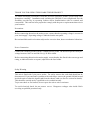
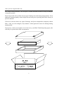
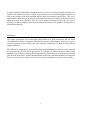
Operators & Service
Manual
DN3600C
Version 3.0C
TELEX PRO AUDIO GROUP
Klark Teknik Building
Walter Nash Road, Kidderminster
Worcestershire DY11 7HJ
England
Tel: (01562)741515 Fax: (01562)745371
CONTENTS
DECLARATION OF CONFORMITY
3
INTRODUCTION
INSTALLATION
INSTRUMENT FAMILIARISATION
GETTING STARTED
Q SWITCHING
MEMORY OPERATION
AUTO EQ
AUTO GAIN
MASTER/SLAVE OPERATION
7
8
9
10
12
13
14
17
18
REFERENCE SECTION:
DETAILS OF OPERATION
DEFAULT/START UP
FADER ADJUSTMENT
GAIN ADJUSTMENT
CURVE/FADER
MORE EQ
A : B : LINK
UTILITIES
BYPASS AND RESET
MORE EQ MENU AND DISPLAY
FILTERS
A : B : LINK
IN/OUT
EXIT
FILTER ADJUST
NOTCH1/2
20
20
20
20
20
21
21
21
21
22
22
22
22
22
23
23
23
24
24
24
24
24
24
25
25
25
25
25
BACK
UTILITIES MENU
AUTO/Q
MEMORY
MORE...
EXIT
AUTO/Q MENU
AUTO GAIN
AUTO EQ
Q TYPE
EXIT
1
MEMORY/LOCKOUT MENU
RECALL
SAVE
LOCK
FULL
PARTIAL
EXIT
MORE... MENU
SLAVES
STAND ALONE
ALL
SLAVES 1 TO 64
MIDI CHAN
ADJ. LCD
INV LCD
FREQUENCY ENCODER
LEVEL ENCODER
EXIT
26
26
26
27
27
27
27
28
28
28
28
28
29
29
29
29
29
29
TECHNICAL SPECIFICATION
MENU STRUCTURE
30
31
SERVICE INFORMATION:
FUSE SPECIFICATION
MIDI CONNECTIONS
VOLTAGE CHANGE OVER
34
34
34
SCHEMATIC DIAGRAMS
36
2
DECLARATION OF CONFORMITY
The Directive Covered by this Conformity
89/336/EEC Electromagnetic Compatibility Directive, amended by 92/31/EEC & 93/68/EEC.
73/23/EEC Low Voltage Directive, amended by 93/68/EEC.
The Products Covered by this Declaration
Equipment Type
Graphic Equaliser
Preset Equaliser
Parametric Equaliser
Dynamics Processor
Audio Analyser
Crossover
Delay Line
Programmable Equaliser
Remote Control System
Crossover
Programmable Equaliser
Product Name
DN300
DN320
DN405
DN500
DN6000
DN800
DN7204
DN3600
DN3698
DN8000
DN4000
Variants
DN360, DN301, DN332
DN330
DN410
DN504, DN510, DN514
DN7103
DN3601
DN3603
The Basis on which Conformity is being Declared
The Products named above and hence the Variants thereof listed above comply with the requirements of the above EU directives by meeting the following standards:
EN 50081-1 (EN55022 class B)
EN 50082-1 (IEC801 Part 2, 4 / ENV 50140 / ENV 50141
EN 60065.
Signed:
Authority:
Date:
.
..........................
N. G. Tembe
Head of Engineering, EVI Audio (U.K.) Plc
1st January 1997
Attention!
The attention of the specifier, purchaser, installer or user is drawn to the special limitations to
use which must be observed when these products are taken into service to maintain compliance
with the above directives. Details of these special measures and limitations to use are available
on request, and are also contained in product manuals.
3
Attention!
Cables:
This product should only be used with high quality, screened twisted pair audio cables, terminated with metal bodied 3-pin XLR connectors. The cable should be connected to pin 1. Any
other cable type or configuration for the audio signals may result in degraded performance due
to electromagnetic interference.
Electric Fields:
Should this product be used in an electromagnetic field that is amplitude modulated by an
audio frequency signal (20Hz to 20KHz), the signal to noise ratio may be degraded. Degradation of up to 60dB at a frequency corresponding to the modulation signal may be experienced
under extreme conditions (3V/m, 90% modulation).
4
THANK YOU FOR USING THIS KLARK TEKNIK PRODUCT
To obtain maximum performance from this precision electronic product, please study these
instructions carefully. Installation and operating the DN3600 is not complicated, but the
flexibility provided by its operating features merits familiarisation with it's controls and
connections. This unit has been prepared to comply with the power requirements that exist in
your location.
Precautions
Before connecting the unit to the mains power, ensure that the operating voltage is correct for
your local supply. Operating voltage is indicated on the rear panel.
Do not install this unit in a location subjected to excessive heat, dust or mechanical vibrations.
Power Connection
Connection is made by means of an IEC standard power socket. The unit will operate off any AC
voltage between 100 Vac and 240 Vac @ 50 Hz to 60Hz.
Before connecting this unit to the mains supply, ensure that the fuse fitted is the correct type and
rating, as indicated on the rear panel, adjacent to the fuse holder.
Safety Warning
This unit is fitted with 3-pin power socket. For safety reasons the earth lead should not be
disconnected. If you encounter a problem with earth-loops, remove the ground-lift link located
inside the unit to isolate the signal earth from the chassis earth (see Service section for details).
This should be carried out by a qualified service technician only.
To prevent shock or fire hazard, do not expose the unit to rain or moisture.
To avoid electrical shock, do not remove covers. Dangerous voltages exist inside. Refer
servicing to qualified personnel only.
5
After you have unpacked the unit
Save all the packing materials - they will prove valuable should it become necessary to transport
or ship this product.
Please inspect this unit carefully for any signs of damage incurred during transportation. It has
undergone stringent quality control inspection and tests prior to packing and left the factory in
perfect condition.
If, however, the unit shows any signs of damage, notify the transportation company without
delay. Only you, the consignee, may institute a claim against the carrier for damage during
transportation.
If necessary, contact your supplier or as a last resort, your Klark Teknik importing agent, who
will fully co-operate under such circumstances.
6
INTRODUCTION
Designed to meet and exceed the needs of the recording, broadcast, installation and live sound
industries, the Klark Teknik DN3600 Programmable Graphic Equaliser is an extremely high
quality, digitally controlled, two-channel, third-octave equaliser that combines state-of-the-art
audio performance with unprecedented ease of use. The two channels may either be used
independently or linked for stereo use. To further extend the flexibility of the equaliser, the unit
also incorporates variable frequency low and high-pass filters, two notch filters with variable
frequency and depth and overall gain adjustment.
Featuring a very large backlit LCD display window, the DN3600 may store up to 66 equaliser
programs and the inclusion of a Pro MIDI interface enables several other DN3600s or DN3601
slave units (64 maximum) to be controlled from a single DN3600. The slave units are electrically
identical to the DN3600 but have limited control and display facilities. A 16-pin connector is
provided for use in conjunction with the DN60/DN6000 Real Time Spectrum Analyser enabling
room analysis and equalisation to be accomplished automatically.
The proprietary analogue filters are based around the Klark Teknik “MELT” hybrid filter circuits
which offer far greater headroom and dynamic range than is possible using standard 20-bit linear,
digital systems. Benefiting from revised circuitry, these filters are exceptionally reliable and
offer greater stability than discrete designs. They are also relatively immune to electromagnetic
interference, unlike coil-based filters. Separate supply rails are used for the digital and analogue
circuitry which, in combination with rigorous internal screening, ensures the cleanest possible
audio signal path.
In order to provide maximum operational flexibility, the system includes a switchable Q mode.
The Low Q setting (Q:360) provides an accurate emulation of the industry-standard DN360
equaliser. In High Q mode (Q:27), the performance emulates the DN27.
To maintain the optimum signal to noise ratio and headroom at all equaliser settings, the gain
control acts on the equaliser sections themselves rather than being a simple pre or postequalisation gain stage. Additionally, an Auto gain mode is included in the system which
automatically scales the gain of the individual equaliser bands as cut or boost is applied to reduce
the risk of accidental clipping and to maintain a safe working headroom.
Both the input and output circuitry is electronically balanced with a nominal operating level of
+4dBu. The output circuitry is based on the Midas XL3 output stage, giving exceptionally high
drive capability. A transformer option is available for both inputs and outputs.
7
In order to make the DN3600 as straightforward to use as a conventional graphic equaliser, the
backlit LCD window provides a ‘virtual’ representation of a conventional graphic equaliser as
well as the settings of the shelving high and low-pass filters and the notch filters. The use of
multi-function buttons for regularly accessed functions has been avoided to enable the unit to be
adjusted quickly and efficiently while the Curve display function provides the user with a
frequency response display based on the combined operation of the graphic, shelving filters,
notch filters and gain.
Installation
The inputs and outputs are electronically fully balanced on XLR connectors and are wired
conventionally with pin 1 as ground. Because the system is fully floating, either pin 2 or pin 3
can be designated as hot so long as the same protocol is adhered to for both the input and the
output connectors.
The DN3600 is designed for use in both fixed and mobile installations where it can be mounted
in a conventional 19 inch rack occupying just 2U of height. In mobile situations where rough
handling is a possibility, it is advisable to support the rear of the unit to prevent undue stress being
placed on the front panel. Ensure that the unit has sufficient ventilation and that it is not placed
directly over any device which runs hot such as a power amplifier or console power supply.
8
Instrument Familiarisation
Front panel functions
DISPLAY SCREEN: This is a large, backlit "Supertwist"-type LCD which shows white/green
legend on a blue background. Menu options are listed down the left hand end. Various status
information is shown along the top edge. In normal operating mode, the largest part of the screen
displays the "Virtual" graphic equaliser faders for one channel. LCD contrast is adjusted via a
menu option. See the Adj. LCD section for more details. In addition the LCD backlight features
a bright up feature which increases the LCD backlight brightness when the controls are operated.
The bright up period can be set under software control via the Adj. LCD menu from 2 seconds
to 60 seconds.
FREQUENCY BUTTONS: These 30 dedicated keys, each labelled with a separate ISO centre
frequency, are used to select graphic frequency bands and to set low pass, high-pass and notch
filter positions. A number of adjacent bands may be selected by pressing two keys either at once
or in quick succession. The selected ‘fader’ or 'faders' in the display window may be adjusted by
means of the LEVEL control. An alternative method of frequency selection is to use the FREQ
rotary control.
FREQ: This rotary control may be used to select any of the equaliser bands for adjustment as
an alternative to using the Frequency buttons. Also, a number of adjacent faders may be selected
by holding a single button until it flashes and then using the FREQ rotary control. The FREQ
rotary control may also be used to set the frequency of Notch filters and of the High pass filter.
LEVEL: This rotary control is used to adjust the level of any selected faders - including the Gain
fader. It may also be used to set the attenuation of the Notch filters and the frequency of the Low
pass filter.
BUTTONS 1-4: These “soft keys” are used to select and operate the various functions of the
equaliser. The functions immediately available depend on the current operating mode of the unit.
The current function attached to each key is shown on the LCD display beside it.
CURVE/FADER: This button is used to switch between the virtual fader display and a
composite frequency response curve, calculated from the positions and shapes of all Graphic,
High pass, Low pass and Notch filters and gain control. The curve changes in real time with any
adjustments made.
9
GAIN: This button selects the Gain fader for adjustment. The Gain fader is highlighted and can
be adjusted in 0.5dB steps from +6 to -18dB. One step below the -18dB point mutes the selected
channel. To deselect the Gain fader press GAIN a second time.
The Gain control on the DN3600 scales the actual frequency bands. This achieves optimization
of signal to noise ratio from one simple control and avoids the disadvantages of conventional pre
EQ or post EQ gain controls.
NUMERIC WINDOW: Displays the number of the currently operating Memory and, in the
appropriate operating modes, the Slave address number or the MIDI channel number. A flashing
number indicates access by a remote control device, such as another DN3600.
METERS: Separate 10-segment bargraph level meters monitor the signal level in channels A
and B over the range -12dB to +15dB. The Clip warning LED monitors seven different points
within the circuitry of the DN3600 and flashes if the level at any point comes within 2dB of
clipping.
POWER SWITCH: Switches the unit on and off. When the unit is off, there is a hard relay bypass
which connects the input signal directly to the output.
Rear Panel Functions
Balanced Input XLR Sockets
Balanced Output XLR Sockets
Pro MIDI XLR Connectors: These follow the same wiring convention as conventional MIDI
DIN sockets. These are used for performing system exclusive data transfer and for linking
multiple units in a master/slave configuration. See service section for wiring convention.
16-Pin IDC Interface: Interfaces directly with the DN60/DN6000 Real Time Spectrum Analyser
for automatic equalisation and may be used to interface with future products.
IEC Mains Socket with integral fuse.
10
GETTING STARTED WITH THE DN3600
The operation of the virtual faders is much like that of a conventional graphic equaliser in that
a ‘fader’ is selected and then moved. Faders may be selected directly by pressing any one of the
Frequency buttons or the bands may be ‘scanned’ through using the FREQ rotary control. The
selected fader is then adjusted by use of the LEVEL rotary control.
More than one band may be selected by pressing and holding one of the Frequency keys until it
flashes and then either pressing another Frequency key or rotating the FREQ control. A bank
of faders can also be selected be pressing two keys at the same time or in quick succession.
Moving the LEVEL control will now adjust all selected bands simultaneously.
Exit from bank selection is by pressing a single frequency key.
SELECTING CHANNELS: The user may adjust channels A and B independently or both
together. Channels are selected by pressing the A : B : Link key. The Link mode may be selected
by pressing and holding the A : B : Link key. In Link mode, any adjustments made to the fader
positions affect both channels. If Link mode is entered from channel A, the screen continues to
display channel A. Channel B will follow changes to channel A. If Link mode is entered from
channel B, the screen continues to display channel B. Channel A will follow changes to channel
B.
FILTERS: Access to the high and low pass filters and notch filters is via the More EQ key. Filter
and notch positions are displayed on a frequency response curve that changes in real time with
any adjustments. The user may select the filters of either channel for adjustment by pressing the
A : B key, and may switch the filters in or out of circuit by use of the In/Out key. Pressing the
Filters key allows the individual filters to be adjusted.
The High-Pass filter covers the range 20Hz to 400Hz in one third octave steps while the LowPass filter covers the range 1.6kHz to 30kHz, again in one third octave steps. These filters have
a 12dB/octave slope characteristic. When selected by pressing the
key, the High pass
and Low pass filter frequencies are displayed at the top of the screen. They may be adjusted either
by use of the FREQ and LEVEL rotary controls respectively, or by pressing the Frequency keys.
Both Notch filters cover the range 20Hz to 20kHz in one twelth octave steps and provide up to
12dB of attenuation. When a notch filter is selected, its attenuation and frequency are displayed
at the top of the screen. The Notch may be adjusted by use of the LEVEL control and either the
FREQ control or the Frequency keys.
11
Q SWITCHING
Over the last 15 years, Klark Teknik's graphic equalisers have become "industry standards" with
audio professionals around the world - some preferring the smooth, averaging quality of the
DN360 - others, the sharper, tighter Q character of the DN27. To satisfy these individual
preferences, the DN3600 incorporates two "Q" options - 360 and 27.
The DN3600 utilises 30 "combining" 1/3 octave filters. This combining action allows adjacent
filters to act over the area in between their own centre frequencies to create smooth but complex
frequency response curves with minimal ripple and phase error.
Q:360
On this setting, at low boost or cut the filters exhibit a relatively wide Q which results in a smooth
response with very low ripple and phase error. At high boost or cut, the filter Q sharpens to allow
notching/accentuation of particular frequencies with just enough combining to provide cut/boost
in between adjacent bands.
Q:27
At full boost or cut, this setting is the same as Q:360. At lower settings of boost or cut, although
the filter Q widens, it remains sharper than the Q:360 at an equivalent gain. This gives more
precise control of the EQ curves, but means that careful setting of the filters is required to create
smooth curves with minimal ripple and phase error.
To change Q, press the soft keys labeled Utilities, Auto/Q and Q Type in turn. Pressing the Q
Type key toggles between Q:27 and Q:360 and the Q mode is shown at the top of the screen.
12
MEMORY OPERATION
Equalisation programs may be created from scratch or existing programs may be called up and
modified.
To start from scratch, switch OUT the More EQ and reset the unit by pressing and holding the
Bypass key for more than 5 seconds.
RECALLING A MEMORY
Select Utilities, Memory and Recall in turn on the soft keys. Then use the FREQ rotary control
to select the required memory by number (shown in the NUMBER window) or name (shown,
together with the fader positions, on the LCD screen). Press the Recall key a second time to
complete the procedure. The number of the current memory remains in the NUMBER window.
SAVING A MEMORY
Select Utilities, Memory and Save in turn on the soft keys. The memory number defaults to that
last used, although a new memory location may be entered if desired. Use the FREQ or LEVEL
rotary controls to select the memory location by number, and use the Frequency keys to give the
new memory a name, or to overwrite the previous name. The < key has a backspace function.
The SHIFT key gives access to the numbers 0 to 9. To complete the storage procedure, press the
Save key a second time. The data from both channels is saved to the new location, regardless
of the Link status.
Note: Whenever parameters are adjusted, the revised data is placed in a temporary store so that
the original memory data is not overwritten until it is deliberately saved. When the unit is
switched off, the temporary store is not lost. On switch on, the unit will return exactly to the state
at switch off.
13
AUTO EQUALISATION - THE DN3600/DN60 CONNECTION
The DN3600 can be interfaced with the Klark Teknik model DN60 Real Time Spectrum
Analyser. The combination can then be used to perform an Automatic Equalisation function, to
compensate for the sound system frequency response. To do this, proceed as follows:
1. Make certain that both units are switched OFF. Connect the DN60 to the DN3600. The
interconnection is made using the pin-to-pin 16-way cable supplied with the DN3600. The
cable should be used to connect the DN60 "PLOTTER INTERFACE" to the DN3600 "DN60
INTERFACE". Switch ON the DN60 first, let initialise, then switch ON the DN3600.
2. Feed the signal from the DN60 pink noise source through a level control device, such as a
mixing console, into the DN3600 input - whichever channel is to be equalised. Keep the pink
noise level down at this point. Make certain that any other equalisation in the pink noise
signal path, such as on a mixing console input channel, is set to a flat position.
3. Set the DN60 microphone at the desired listening/measurement position in the venue.
4. Slowly bring up the level of the pink noise through the sound system to an average listening
level.
5. Set the DN60 controls to Avg., Cont., Resp 3., 1 dB resolution, mic input. Adjust the DN60
Reference Level until the full frequency response display is seen.
5. Switch the More EQ section OUT (More EQ, In/Out, Exit if required).
6. Enter the DN3600 Auto/Q menu (Utilities, Auto/Q). Repeatedly press the Auto EQ button
allowing sufficient time between presses for the DN60 display to settle. Continue until a flat
response is obtained on the DN60 display. Six to eight iterations are usually enough. It may
be necessary to adjust the DN60 Reference Level between iterations.
What happens is this. On each iteration the DN3600 obtains the measured room response from
the DN60, calculates the room response correction, limits it to +/-4 dB and adds this to the current
Graphic settings. With each iteration the measured response gets closer and closer to flat until
finally all the DN3600 is doing is to correct minor random variations.
Note. The DN3600 should not be in bypass mode. If it is the room correction curve will still be
added to the DN3600 settings but the measured response will not be affected and the Auto EQ
function will not perform as specified.
14
Equalising to a Preferred Curve
Whilst the Auto EQ function tries to equalise to flat (as measured by the DN60) it is possible to
perform an approximate Auto EQ to a preferred house curve by making use of the Bypass setting
of the DN3600.
To do this set up the house curve on the DN3600, or Recall the desired curve from memory (the
memory itself will not be modified by the Auto EQ function). Connect the DN60 and DN3600
as defined in 1. above. Inject pink noise into the system as defined in 2. above. Measure the room
response as described in the DN60 operators manual. Bypass the DN3600. Perform the Auto
EQ function once and once only. Do not iterate.
Note. The spectrum display may be"frozen" by saving it to a DN60 memory and switching to
mem. mode.
The room response is corrected subject to the Auto EQ adjustment limit of +/-4 dB. This Auto
EQ adjustment limit is the reason for the approximate room correction.
The reason for performing the Auto EQ function only once is because the measured spectrum
of
the pink noise is not modified by the DN3600. With the equalise to flat connection defined above
each iteration brings the overall system response (including the DN3600) closer to flat. With the
DN3600 bypassed this cannot happen. Hence the same correction factor would be added each
time.
15
AUTO EQUALISATION - THE DN3600/DN6000 CONNECTION
The DN3600 can be interfaced to the Klark Teknik model DN6000 Audio Analyser or DN60
Real
Time Spectrum Analyser. The combination can then be used to perform an Automatic
Equalisation
function to compensate for the room or system frequency response. To do this with the DN6000
proceed as follows:
1.
2.
3.
4.
5.
6.
7.
8.
Connect the DN6000 to the DN3600. The interconnection is made using the pin-to-pin 16
way cable supplied with the DN3600. The cable should be used to connect the DN6000
"DN3600 INTERFACE" to the DN3600 "DN60 INTERFACE". This connection should
be made with the DN6000 switched OFF.
Set up the DN6000 in Frequency mode.
Set the output utility to unfiltered pink noise.
Switch weighting to Flat.
Switch off Peak Hold.
Set Scale to 60dB.
Set resptime to 1 second or more.
Feed the signal from the DN6000 output into the DN3600 input - whichever channel is to
be equalised.
Set the DN6000 microphone at the desired listening/measurement position.
Switch the More EQ section OUT (More EQ, In/Out, Exit if required).
Make sure that the DN6000 is not muted and is running.
Adjust the Level and Level Trim controls of the DN6000 so that the spectrum analysis is
displayed as much as possible in the upper half of the LCD.
Enter the DN3600 Auto/Q menu (press Utilities, Auto/Q). Repeatedly press the Auto EQ
button allowing sufficient time between presses for the DN60 display to settle. Continue
until a flat response is obtained on the DN6000 display. Six to eight iterations are usually
enough. It may be necessary to adjust the DN6000 Level Trim control between presses.
What happens is this. On each iteration the DN3600 obtains the measured room response from
the DN6000, calculates the room response correction, limits it to +/- 4dB and adds this to the
current Graphic settings. With each iteration the measured response gets closer and closer to flat
until finally all the DN3600 is doing is to correct minor random variations.
Note: The DN3600 should not be in bypass mode. If it is the room correction curve will still be
added to the DN3600 settings but the measured response will not be affected and the Auto EQ
function will not perform as specified.
16
Equalising to a Preferred Curve
Whilst the Auto EQ function tries to equalise to a flat response (as measured by the DN6000),
it is possible to perform an approximate Auto EQ to a preffered house curve by making use of
the Bypass setting of the DN3600.
To do this set up the house curve on the DN3600 faders, or Recall the desired curve from memory
(the memory itself will not be modified by the Auto EQ function). Connect and set up the
DN6000 and DN3600 as defined above. NOTE: The spectrum display may be "frozen" by
switching off Run on the DN6000. Press Bypass on the DN3600. Perform the Auto EQ function
once and once only. Do not iterate.
The room response is corrected subject to the Auto EQ adjustment limit of +/- 4dB. This Auto
EQ adjustment limit is the reason for the approximate room correction.
The reason for performing the Auto EQ function only once is that the measured spectrum of the
pink noise is not modified by the DN3600. With the equalise to flat connection defined above
each iteration brings the overall system response (including the DN3600) closer to flat. With the
DN3600 bypassed this cannot happen. Hence the same correction factor would be added each
time.
AUTO GAIN
The Auto Gain function, when activated, assists in making the best use of the dynamic range and
headroom of the DN3600. When frequency bands are boosted, the average signal level rises and
it is advisable to reduce the gain of the equaliser to prevent overload. When frequency bands are
cut, the average signal level falls and it is advisable to increase the gain of the equaliser to
maintain the optimum signal to noise ratio. When some bands are boosted and some bands are
cut, the situation becomes more complicated, especially as the energy spectrum of a typical
musical or vocal signal is far from flat across all the frequency bands.
The Auto Gain function is activated by pressing Utilities, Auto/Q, Auto Gain, and deactivated
in the same way. When activated, the DN3600 compares any new filter adjustments to a model
of the energy response of a typical musical signal, and adjusts the Gain control to compensate
- thus helping to make optimum use of the headroom. The Gain fader will flash as it moves to
show its operation. Auto gain status is indicated by text at the top of the Gain fader.
17
MASTER/SLAVE OPERATION
The Klark Teknik Pro MIDI Master/Slave system allows up to 65 DN3600 and DN3601
units to be operated, either individually or together, from the front panel of one DN3600.
The system is simple to connect, simple to operate and protects itself from the dangers of
unreliable power supply and damaged connections.
Once programmed, the equaliser program memories resident in the slaves may be selected via
ordinary MIDI program change commands without the need for a DN3600 master unit. This
provides an economical way of managing a large installation as the slave system is both cost
effective and secure from inadvertent tampering.
Master/Slave configuration is automatic when two or more DN3600 and/or DN3601 units are
linked in a closed loop via their Pro MIDI interfaces - MIDI OUT to MIDI IN.
Note: The loop must be closed. Each MIDI OUT must be connected to the next MIDI IN. If
MIDI program change messages from some other device are to be injected onto the Klark Teknik
loop, this must be done via a MIDI MERGE unit.
MIDI Signal Flow:
MIDI Merge
Optional
Master
Slave
Slave
Slaves
18
Any DN3600 in the loop can be designated as the Master by entering the Slaves sub menu (press
Utilities, More..., Slaves). The other DN3600 and DN3601 units in the loop will automatically
configure themselves as slaves, with the first being number 1, the second being number 2 and
so on. A maximum of 64 slaves may be connected in this way (65 units including the Master).
To address an individual slave unit, enter the Slaves sub-menu of the Master. The slave address
number can now be changed using the FREQ rotary control. Press the Slaves soft key a second
time to initiate control of the selected device.
All the controls and display modes now affect only the selected slave unit. The number of the
selected Slave is displayed as highlighted text at the top of the LCD screen. Only the Slaves, Lock
and Adj. LCD sub menus relate to the Master unit. To address another slave, enter the Slaves
sub menu and select a new slave number.
To address all the units in the loop, enter the Slaves sub menu and select SELECT ALL. All
functions and controls now affect all units including the Master. For example, performing an
Auto EQ function now will adjust all the units in the loop to equalise the spectrum of the DN60/
DN6000 connected to the master.
To return to normal operation, ie adjustment of the Master itself, the Slaves selection must be
returned to “STAND ALONE”. The slave units will retain their current settings until changed.
All controls and display modes now affect only the Master unit.
Note: A MIDI loop can only have one Master. Initiation of another master by entering its Slaves
menu will cancel the original master and renumber the loop.
OPERATION FROM THE FRONT PANEL WHEN UNDER REMOTE CONTROL
There are two responses to front panel input when under remote control:
If the unit is individually selected - the front panel controls are disabled.
If all the units are selected i.e. SELECT ALL - the front panel controls are enabled but the first
action is used to override the remote control.
VISUAL INDICATION OF REMOTE CONTROL
A unit when selected will respond by changing its operating mode and displaying the following:
DN3600 V3.0 software and DN3600C V3.0C software - Dynamic screen operation i.e.the fader
knobs etc. will move in response to remote control messages. The NUMBER window displays
the slave number during the selection operation. At all other times it displays the current memory
number and flashes when unit is individually selected.
19
DETAILS OF OPERATION
Initial, Default Display
Soft key options: More EQ
A : B : Link
Utilities
Bypass
Fader adjustment
The ‘Virtual’ Graphic Equaliser faders are selected either by pressing the appropriate frequency
key or by rotation of the FREQ rotary control.
There are several ways to select a range of adjacent faders.
1.
Hold a single Frequency key until it starts to flash. This sets one end of the range. Define
the other end of the range by pressing a second Frequency key, or by use of the FREQ
rotary control. The selected fader or faders becomes highlighted.
2.
Press two Frequency keys at the same time.
3.
Press two Frequency keys in quick succession.
The frequency or frequency range of the selected fader or faders is shown in text at the top of the
screen.
The selected fader or faders are adjusted by use of the LEVEL rotary control. The adjustment
range is +/-12dB in half dB steps. The fader level or, in the case of a range of faders, the average
fader level, is shown as text at the top of the screen.
Also shown at the top of the screen are current Memory name, Q-mode and Channel being
addressed.
Gain Adjustment
Pressing the GAIN key at any time toggles between gain adjustment and fader adjustment. When
gain adjustment is selected, the gain fader is highlighted. Gain may be adjusted by use of the
LEVEL rotary control.
The range of adjustment is +6 to -18dB in half dB steps. Below -18dB the unit is muted. While
in Gain Adjust mode, the gain setting is shown in text at the top of the screen. Mute status is
shown by a Muted icon at the top of the screen.
CURVE/FADER
The CURVE/FADER key toggles the screen between Curve and Fader displays. While the
Fader display shows the positions of the 30 Graphic faders for the addressed channel, Curve
display calculates the actual frequency response of the unit, taking into account fader positions,
filter Q and interaction, low and high pass filters, notches and gain. Graphic faders can be
selected and adjusted while viewing the Curve display, which changes to show the adjustments
in real time.
20
More EQ
Soft key 1 is accompanied by the text More EQ. Pressing this key selects the More EQ menu
and the Filter Adjust display. See below. The More EQ menu text will be highlighted if the More
EQ filters for the selected channel are in circuit.
A : B : Link
Soft key 2 is accompanied by the text A : B : Link. Pressing this key toggles between addressing
channels A and B. If the key is held for more than 1 second, the Link mode is selected. In Link
mode, all fader adjustments affect both channels. If Link mode is entered from channel A,
channel A is displayed and channel B follows it. If Link mode is entered from channel B, channel
B is displayed, and channel A follows. The A : B : Link status is shown at the top of the screen
as =A=, =B=, A+B or B+A.
Utilities
Soft key 3 is accompanied by the text Utilities. Pressing this key selects the Utilities menu. See
below.
Bypass and Reset
Soft key 4 is accompanied by the text Bypass. Pressing this key engages a bypass of the graphic
equaliser section. The Gain control and More EQ filters and Notches remain in circuit. If the
Bypass key is held pressed for more than 5 seconds, all the graphic faders of the addressed
channel are reset to the 0dB position.
21
More EQ Menu and Display.
Accessed by pressing the More EQ key from the Start-up menu.
Soft key options: Filters
A : B : Link
In/Out
Exit
More EQ Display
In More EQ mode, the display shows the frequency response curve calculated from the Notch
filter and High Pass and Low Pass filter settings.
CURVE/FADER
When the CURVE/FADER key is pressed, the display incorporates the Graphic fader positions
into the calculated frequency response curve.
Filters
Soft key 1 is accompanied by the text Filters. Pressing this key selects Filter Adjust mode. See
below.
A : B : Link
Soft key 2 is accompanied by the text A : B : Link. Pressing this key toggles between addressing
channels A and B. If the key is held for more than 1 second, the Link mode is selected. In Link
mode, all fader adjustments affect both channels. If Link mode is entered from channel A,
channel A is displayed and channel B follows it. If Link mode is entered from channel B, channel
B is displayed and channel A follows. The A : B : Link status is shown at the top of the screen
as =A=, =B=, A+B, or B+A.
Selection of Link only links the operation of the two channels, it does not copy details between
the channels except when changes are made to certain settings. Full details are provided below
in the section headed Filter Adjust Menu and Display.
In/Out
Soft key 3 is accompanied by the text In/Out. When pressed, the High and Low pass filters and
two Notch filters are switched in or out of circuit. When the channels are linked the currently
displayed channel acts as the master with new settings copied to the alternate channel. The In/
Out status is highlighted on the menu. When the filters are out of circuit, the Filters key is
disabled and the display shows a flat frequency response.
Exit
Soft key 4 is accompanied by the text Exit. When pressed, the key returns the unit to the start
up display and menu.
22
Filter Adjust Menu and Display.
Access by pressing the More EQ key followed by the Filters key.
Soft key options: Notch 1
Notch 2
Back
Display
In Filter adjust mode, the display shows the frequency response curve calculated from the Notch
filter and High Pass and Low Pass filter settings.
CURVE/FADER
When the CURVE/FADER key is pressed, the display incorporates the graphic fader positions
into the calculated frequency response curve.
Notch 1
Soft key 1 is accompanied by the text Notch 1. When pressed and highlighted, the key selects
Notch 1 for adjustment. The Notch filter frequency is set by use of the Frequency keys (1/
3 octave ISO frequencies) or by the FREQ rotary control (1/12 octave steps). When linked the
new frequency setting of the displayed channel is copied to the alternate channel. Notch
frequency is shown as text at the top of the screen.
Notch filter depth is adjusted by the LEVEL rotary control over a range of 0 to -12dB in 1dB
steps. When linked, the settings of the two channels are incrementally linked i.e. the settings of
both channels are increased or decreased by 1dB per click of the rotary control. Notch depth is
shown as text at the top of the screen.
Notch 2
Soft key 2 is accompanied by the text Notch 2. When pressed and highlighted, the key selects
Notch 2 for adjustment. The Notch filter frequency is set by use of the Frequency keys (1/3 octave
ISO frequencies) or by the FREQ rotary control (1/12 octave steps). When linked, the new
frequency setting of the displayed channel is copied to the alternate channel. Notch frequency
is shown as text at the top of the screen.
Notch filter depth is adjusted by the LEVEL rotary control over a range of 0 to -12dB in 1dB
steps. When linked the, the settings of the two channels are incrementally linked i.e. the settings
of both channels are increased or decreased by 1dB per click of the rotary control. Notch depth
is shown as text at the top of the screen.
Soft key 3 is accompanied by the text
. When pressed and highlighted this key selects
the High and Low pass filters for adjustment. The High pass filter frequency is set by the
frequency keys or by the FREQ rotary control. The Low pass filter frequency is set by the
frequency keys or by the LEVEL rotary control. When linked, the setting of the currently
23
displayed channel is copied to the alternate channel during adjustment. High and Low pass filter
frequencies are shown as text at the top of the screen.
Back
Soft key 4 is accompanied by the text Back. When pressed, this key returns the unit to the More
EQ menu.
Utilities menu.
Accessed by pressing the Utilities key from the Start-up menu.
Soft key options: Auto/Q
Memory
More. . .
Exit
Curve/Fader
The Curve/Fader key toggles the screen between Curve and Fader displays. While the
Fader shows the positions of the 30 Graphic faders for the addressed channel, Curve display
calculates the actual frequency response of the unit, taking into account fader positions, filter
Q and interaction, low pass and high pass filters, notches and gain.
Auto/Q
Soft key 1 is accompanied by the text Auto/Q. When pressed, this key selects the Auto/Q menu.
See below.
Memory
Soft key 2 is accompanied by the text Memory. When pressed, this key selects the Memory/Lock
menu. See below.
More. . .
Soft key 3 is accompanied by the text More. . ., meaning “More Utilities”. When pressed, this
key selects the MIDI channel, Slave selection and LCD invert facilities. See below.
Exit
Soft key 4 is accompanied by the text Exit. When pressed, this key returns the unit to the Start
up menu.
24
Auto/Q menu.
Accessed by pressing the Utilities key followed by the Auto/Q key.
Soft key options: Auto Gain
Auto EQ
'Q' type
Exit
Curve/Fader
The Curve/Fader key toggles the screen between Curve and Fader displays. While the
Fader display shows the positions of the 30 Graphic faders for the addressed channel, Curve
display calculates the actual frequency response of the unit, taking into account fader positions, filter Q and interaction, low pass and high pass filters, notches and gain.
Auto Gain
Soft key 1 is accompanied by the text Auto Gain. When pressed, this key toggles the Auto Gain
function on or off and returns the unit to the start up screen.
When Auto Gain is on, the Gain fader will move automatically to compensate for any further
adjustments made to the graphic faders in order to maintain unity gain for an average audio signal.
Auto EQ
Soft key 2 is accompanied by the text Auto EQ. This function is used when the DN3600 is
connected to a Klark Teknik model DN60/DN6000 Real Time Spectrum Analyser via their
respective “DN60 Interface” and “Plotter/Data” ports.
When the key is pressed, the DN3600 reads the frequency spectrum as displayed at that moment
by the DN60/DN6000 analyser. Fader adjustments are then applied to the selected channel (A,
B or - in LINK mode - both) to compensate for the analysed room or system response.
The unit remains in Auto/Q menu, allowing repeated triggering of the Auto EQ function.
Q Type
Soft key 3 is accompanied by the text Q Type. When the key is pressed, the addressed channel
toggles between the Q modes: 360 and 27. The Q mode is shown as text at the top of the screen.
The Q mode determines the shape, and hence the sound and interaction, of the graphic filters.
Q:360 emulates the wide and hence smoothly combining and easy to use filters of the industry
standard Klark Teknik DN360 Graphic Equaliser. Q:27 emulates the narrower and hence less
interactive LCR filters of the older Klark Teknik model DN27 Graphic Equaliser.
Exit
Soft key 4 is accompanied by the text Exit. When this key is pressed, the unit returns to the start
up menu.
25
Memory/Lockout menu
Accessed by pressing the Utilities key followed by the Memory key.
Soft key options: Recall
Save
Lock
Exit
Curve/Fader
The Curve/Fader key toggles the screen between Curve and Fader displays. While the
Fader display shows the positions of the 30 Graphic faders for the addressed channel, Curve
display calculates the actual frequency response of the unit, taking into account fader positions, filter Q and interaction, low pass and high pass filters, notches and gain.
Recall
Soft key 1 is accompanied by the text Recall. This key allows any of the 66 named memories
to be recalled. To recall a memory:
1. Press the Recall key once.
2. The NUMBER window shows the selected memory number while the LCD shows the
memory name and fader positions. Select the required memory by name and/or number
by use of the FREQ or LEVEL rotary control.
3. The procedure may be aborted at any time by pressing the Exit or Save keys.
4. Press the Recall key once more. At this point all the fader, filter, Gain, Q and channel
settings are updated. The unit returns to the start up screen.
The current memory name is shown as text at the top of the screen. The current memory
number is shown in the NUMBER window unless any manual changes are made.
Save
Soft key 2 is accompanied by the text Save. This key allows the current equaliser settings to be
stored in any of the 66 memory locations. Each memory may be given an 8 character name. To
Save a memory:
1. Press the Save key once.
2. Select the memory number by use of the FREQ or LEVEL rotary control. Memory
number is shown in the NUMBER window. Memory name - if any - is shown on the
LCD.
3. If desired, enter a new memory name or edit the old memory name using the Frequency
keys. These correspond to the letters A to Z. By pressing the SHIFT key, the numbers 0
to 9 may also be accessed. The < key is a backspace or delete function.
4. The procedure may be aborted at any time by pressing the Exit or Recall keys.
5. Press the Save key a second time.
All fader, filter, Gain, Q and channel settings together with the name are stored at the selected
memory location. The unit returns to the start up screen.
26
Lock
Soft key 3 is accompanied by the text Lock. This key allows access to the two lock modes. When
the key is pressed, the menu options change to:
Full
Partial
Exit
Full
Full lock prevents access to all controls. After Full Lock has been set, the only action possible is to press the Unlock key and type in a password. If the correct password is typed in, the
Full Lock is defeated.
To set Full Lock:
1. Type in the desired password of up to 8 letters, using the frequency keys.
2. The procedure can be aborted by pressing the Exit key.
3. Press the Full key.
Partial
Partial lock prevents access to all controls except for Memory Recall. After Partial Lock has been
set, the only action possible is to Recall a memory (press the Recall key) or unlock the unit by
pressing the Unlock key and typing in the correct password. If the correct password is typed in,
the Partial Lock is defeated.
To set Partial Lock:
1. Type in the desired password of up to 8 letters, using the frequency keys.
2. The procedure can be aborted by pressing the Exit key.
3. Press the Partial key.
Exit
Soft key 4 is accompanied by the text Exit. Pressing this key returns the unit to the start-up menu.
27
More. . . Utilities menu
Accessed by pressing the Utilities key followed by the More. . . key.
Soft key options: Slaves
MIDI Chan
Adj. LCD
Exit
Curve/Fader
The Curve/Fader key toggles the screen between Curve and Fader displays. While the Fader
display shows the positions of the 30 Graphic faders for the addressed channel, Curve display
calculates the actual frequency response of the unit, taking into account fader positions, filter Q
and interaction, low pass and high pass filters, notches and gain.
Slaves
Soft key 1 is accompanied by the text Slaves. Pressing this key enables the selection of
Slave devices to be addressed. Pressing this key also causes the DN3600 to assume the roll
of Master over any connected DN3600/DN3601 units. Use the FREQ or LEVEL rotary
control to cycle through the various options:
STAND ALONE
The normal mode of operation. All controls and adjustments affect only the one, local DN3600
unit. The DN3600 must always be returned to STAND ALONE mode in order to control itself.
ALL
All controls and adjustments affect all the compatible slave devices connected into the network,
including the local, Master DN3600 unit.
Slaves 1 to 64
The Master/Slave mode of operation. Select a single slave device to address. When a slave is
selected, all controls and adjustments affect that slave only. There are no changes to the local,
master DN3600 unit. The DN3600 must be returned to STAND ALONE mode in order to control
itself.
The procedure may be aborted at any time by pressing the Exit key.
Press the Slaves key a second time to complete the selection. The unit then returns to the start
up screen and provides control over the selected unit(s).
28
MIDI Chan
Soft key 2 is accompanied by the text MIDI Chan. Pressing this switch enables the selection
of MIDI send and receive channels. By use of the FREQ or LEVEL rotary control, select either
OMNI ON mode (receive all channels, send on channel 1) or OMNI OFF mode and one of MIDI
channels 1 to 16.
The procedure may be aborted at any time by pressing the Exit key.
To complete the selection, press the MIDI Chan key a second time. The unit updates its MIDI
channel number and returns to the start up screen.
The DN3600 recognises MIDI program change messages 1 to 66 on its assigned channel, and
maps them to recall memories 1 to 66.
Also, the DN3600 sends MIDI program change messages 1 to 66, mapped to memory recall
commands entered via the front panel.
Adj. LCD
Soft key 3 is accompanied by the text Adj. LCD. This key allows access to the LCD adjustment
screen. When this key is pressed, the menu options change to:
Inv LCD
Exit
Inv LCD
When pressed, this switch toggles the LCD screen between Normal display (white or green
characters and graphics on a blue screen) and Inverted display (blue characters and graphics on
a white or green screen). After toggling the display the unit remains in the Adj. LCD screen.
Frequency Encoder
The frequency encoder may be used to adjust the display brightup time out. The time can be
adjusted between 2 and 60 seconds. The setting is retained in power down.
Level Encoder
The level encoder is used to adjust contrast of the LCD. The setting is retained on power down.
Exit
Soft key 4 is accompanied by the text Exit. When this switch is pressed, the unit returns to
the start up menu.
29
TECHNICAL SPECIFICATION
INPUTS
Type
Impedence (ohm)
Balanced
Unbalanced
Max. level
TWO
Balanced (electronically)
OUTPUTS
Type
Min. load impedence
Source impedence
Max. level
TWO
Balanced (electronically)
600ohm
50ohm
+22dB into >2kohms
PERFORMANCE
Frequency response /EQ flat
Distortion @ +4dBm
Equivalent input noise
(20Hz to 20kHz unweighted)
Overload indicator
Gain
FILTERS
Type
Graphic ISO Centre Frequencies
Tolerance
Maximum Boost/Cut
Step size
High pass filter slope
Step size
Low pass filter slope
Step size
Notch filters
Maximum cut
Step size
20k
10k
+22dBu
+/-0.5dB (20Hz to 20kHz)
<0.02% @ 1kHz
< -94dBu
+19dBu
-18 to +6dB
Revised MELT hybrid
30, 25Hz - 20kHz 1/3 Octave
+/-5%
12dB
1/2dB
12dB/Octave 20Hz - 400Hz
1/3 Octave
12dB/Octave 30kHz - 1.6kHz
1/3 Octave
Two per channel, varying Q
12dB
1/12 Octave and 1dB
POWER REQUIREMENTS
Voltage
Consumption
100 - 240 Vac @ 50 - 60 Hz
<53 VA
DIMENSIONS
Width
Height
Depth
482mm (19 inch)
88mm (3.5 inch)
306mm (12.25 inch)
WEIGHT
Net
Shipping
5 kg
7 kg
30
DN3600C SOFTWARE V3.0C MENU STRUCTURE
MORE EQ
FILTERS
A : B : LINK
A : B IN/OUT
UTILITIES
BYPASS
EXIT
NOTCH 1
NOTCH 2
BACK
AUTO/Q
MEMORY
AUTO GAIN
AUTO EQ
Q TYPE
EXIT
MORE
MIDI CHAN
EXIT
SLAVES ADJ. LCD
INV LCD
EXIT
RECALL
SAVE
FULL
PARTIAL
UNLOCK
UNLOCK
LOCK
EXIT
EXIT
RECALL
31
EXIT
32
Service
Information
33
SERVICE INFORMATION
Caution: These servicing instructions are for use by qualified personnel only. To reduce the risk
of electric shock, do not perform any servicing other than that contained in the Operating
Instructions unless you are qualified to do so. Refer all servicing to qualified service personnel.
Klark Teknik PLC accepts no liability for damage or injury arising from incorrect servicing.
Fuse ratings:
Rear panel fuse holder:
500mAT
Battery Replacement
Caution!:
Danger of explosion if battery is incorrectly replaced. Replace only with the same or equivalent
type recommended by the manufacturer. Discard used batteries according to the manufacturer's
instructions.
Advarsel!:
Lithiumbatteri. Ekxplosionsfare ved feijlagtig handtering af samme fabrikat og type. Lever det
brugte batteri tilbage till leverandoren.
MIDI Connections
DN3600 Pro MIDI XLRs correspond to standard MIDI 5-pin DIN connectors thus:
DIN
Pin 5
Pin 4
Pin 2
XLR
-
data
+5V
GND
-
Pin 3
Pin 2
Pin 1
Voltage Change-Over
The unit automatically adjusts to any input voltage in the range 100 to 240 Vac @ 50 to 60 Hz.
34