1
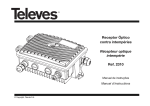
MS11-20-1.qxd
20.09.00 12:57
Seite 1
GigaSwitch 11/20G
GigaSwitch 11/20K
Installation Manual and User
Instructions
MS11-20-1.qxd
20.09.00 12:57
Seite 2
Contents
1
2
3
3.1
3.2
3.3
3.4
4
4.1
4.2
5
5.1
5.2
5.3
5.4
5.5
6
7
8
9
F un ct io n . . . . . . . . . . . . . . . . . . . . . . . 2
S a fe ty Ad v ice . . . . . . . . . . . . . . . . . . . 3
I nt r od uc ing t h e co m p on e n t s . . . . . . . . . 3
GigaSwitch 11/20G . . . . . . . . . . . . . . . . . . . . . . . . . . . . . . .3
GigaSwitch 11/20K . . . . . . . . . . . . . . . . . . . . . . . . . . . . . . .3
Intermediate Amplifier 9Z . . . . . . . . . . . . . . . . . . . . . . . . . .4
Distributor 9V . . . . . . . . . . . . . . . . . . . . . . . . . . . . . . . . . . .4
S et t in gs . . . . . . . . . . . . . . . . . . . . . . . 4
Switchable ouputs for each party, 22 kHz or DiSEqC . . . . .4
Settings for terrestrial inputs . . . . . . . . . . . . . . . . . . . . . . . .5
I ns t a llat io n . . . . . . . . . . . . . . . . . . . . . 5
General . . . . . . . . . . . . . . . . . . . . . . . . . . . . . . . . . . . . . . .5
Selecting an external unit . . . . . . . . . . . . . . . . . . . . . . . . . .6
LNBs . . . . . . . . . . . . . . . . . . . . . . . . . . . . . . . . . . . . . . . . .6
Cable . . . . . . . . . . . . . . . . . . . . . . . . . . . . . . . . . . . . . . . . .6
Selecting Antenna Connectors . . . . . . . . . . . . . . . . . . . . . .7
I ns t a llatio n H int s . . . . . . . . . . . . . . . . . 7
I ns t a llatio n exa m p les . . . . . . . . . . . . . . 8
Tr o ub le s ho ot in g G uid e . . . . . . . . . . . . . 1 1
Te ch nic al Dat a . . . . . . . . . . . . . . . . . . . 1 2
1 Function
The GigaSwitch 11/20 multiswitch is used to supply between 20 and 120 receiving participants with a satellite intermediate frequency as well as with a terrestrial signal.
The following combinations can be distributed by this piece of equipment::
>
two full bands of the Astra satellite Low and High Band plus the EUTELSAT Low and
High Band;
or
>
four satellites of your choice with two polarisation planes each;
or
>
eight individually selected polarisation planes.
>
In addition, FM, VHF and UHF inputs are available for distribution of terrestrial signals.
The GigaSwitches comply fully with the Astra IES concept (integrated reception system).
The star-form distribution provided by the GigaSwitch 11/20 multiswitch provides the advantage of permitting reception of other satellite services to receiving parties without any additional installation.
2
MS11-20-1.qxd
20.09.00 12:57
Seite 3
2 Safety Hints
For your own protection, you should read the safety hints carefully before installing the
GigaSwitch multiswitch. The manufacturer accepts no responsibility for damage caused by
non-observance of the safety hints, or by inappropriate handling.
>
>
>
The components must be mounted in dry rooms on flat, non-flammable surfaces.
Air circulation slots on the components must permit unimpeded circulation.
The installation must be carried out while the unit is not connected to the power
mains.
>
The multiswitch must be connected to ground (earthed).
>
The antenna installation must comply with local regulations relating to lightning protection.
>
The relevant EU standards as well as VDE or national regulations relating to electrical
safety must be observed.
>
National regulations relating to broadcast reception equipment must be observed.
>
Never open the unit cover, as you may be subject to an electrical shock!!!
>
If it becomes necessary to open the unit, this should only be carried out by trained
personnel.
In the following cases, you should disconnect the unit from the power mains, and call an
expert/trained personnel:
>
When the unit has been subject to extreme humidity, or when liquid has entered the
unit;
>
When the unit malfunctions;
>
If the unit shows severe external damage.
3 Introducing the components
3.1 GigaSwitch 11/20G (Part No. 0000/3229)
The GigaSwitch 11/20G is the basic unit in the multiswitch range. The GigaSwitch 11/20G
provides distribution of the Intermediate Frequency signal to 20 participants, including provision of power to the LNBs. In larger installations it also provides the power for the cascade
multiswitch GigaSwitch 11/20K, for the distributor 9V and for the intermediate amplifier 9Z.
When installing a cascade system of several components, please ensure that the maximum
power voltage is not exceeded (see technical specifications).
3.2 GigaSwitch 11/20K (Part No. 0000/3228)
The GigaSwitch 11/20K is the cascade unit in the multiswitch range. This unit receives its
power supply from the basic unit GigaSwitch 11/20G. The GigaSwitch 11/20K unit can thus
only be used in conjunction with the basic unit. The GigaSwitch 11/20K is inserted between
the LNBs and the basic unit, with each additional 11/20K unit providing connections for 20
participants.
The function of the cascade is to distribute the eight polarisation planes as well as the terrestrial signal further along the main connection, and to provide up to 20 participants with independent access to the selected band.
3
MS11-20-1.qxd
20.09.00 12:57
Seite 4
3.3 Intermediate Amplifier 9Z (Part No. 000/3231)
The intermediate amplifier 9z has been designed to compensate for the damping effect of
25m of multimedia cable, or of 40m of CoaxSat 2150 cable, when used to transmit satellite
signals. The amplification of terrestrial signals can be adjusted.
3.4 Distributor 9V
This is used to achieve a three-way split of main-line connections, while providing a high
degree of insulation.
A cascade switch can be connected directly to the lower outputs. The outputs at the front
can be used to feed a further 2 cascade units, using up to 20m of multimedia cable.
One or more distributors can thus be used to assemble fairly large installations.
>
Where the damping of the main line connection is less than 5 dB (at 2150 MHz), no
intermediate amplifier is required. The intermediate amplifier 9Z is only required
where higher damping levels are present.
4 Settings
4.1 Switchable outputs for each party, 22 kHz or DiSEqC control
On the side panels of the unit, above each of the uppermost participant output connections
you will find a switch with which you may set the reaction of the specific output connector
with regard to 22 kHz or DiSEqC control. These switches relate exclusively to parties 1 and
2, as well as to parties 11 and 12. They are provided for receivers that do not provide a
DiSEqC control facility. For such receivers you must select individually the inputs you wish to
address with the 22 kHz control.
a) Position A/B
If the switch is in this position, the Low Band of Position A will be received without the 22
kHz control signal, and the Low Band of Position B will be received with the aid of the 22
kHz control signal.
b) Band Low/High
If the switch is in this position, the Low Band of Position A will be received without the 22
kHz control signal, and the High Band of Position B will be received with the aid of the 22
kHz control signal.
22kHz schalten
Position A/B
Band Low/High
< Abzweig 2
The switches are preset to Position A/B at the factory so that receivers which do not have
4
MS11-20-1.qxd
20.09.00 12:57
Seite 5
DiSEqC control functions can utilise the 22KHz control signal to switch to the Low Band setting of Eutelsat 13°. All other outputs are fixed in terms of their switching position.
The setting of this switch is irrelevant for and not applicable to DiSEqCcompatible receivers.
4.2 Setting of terrestrial Inputs
Terrestrial signals can be fed into the system in separate bands, or as a broad band signal.
Use the switch provided to set the required function:
a) Switch in up position
Separate inputs for VHF, UHF and FM are activated.
b) Switch in down position
The VHF and UHF inputs are deactivated, and should be terminated with 75 Ohm resistors.
The broad band signal is fed into the system via the FM (UKW) connector.
VHF
UHF
/
/
UKW
Breitband
The distribution system is designed to cope with the damping effect of cable up to about 20
dB (between LNBs and antenna connector) at 2150 MHz. An active diagonal plane compensation is implemented in order to compensate for cable damping in the satellite range. The
high level of decoupling of the satellite signals means that damping compensators in the
main line connections are not required. The required level of damping can be achieved by
varying the cable type, dependent on the cable length.
The input level should be at 75 dBµV
It is possible to configure the terrestrial frequency range with 42 channels in accordance with
CENELEC regulations. Likewise, due to the carefully designed low-damping system for terrestrial reception with diagonal compensation there will be no problem in future to accommodate DVB-T or DVB-C (terrestrial or cable-fed digital television).
5 Installation
5.1 General
>
>
>
>
>
We recommend that the star-form distribution should originate in the attic, or near the
centre of the house/building.
Should the distribution originate in the cellar/basement, we recommend you fit an interim amplifier Type 9Z between the basic unit multiswitch and the LNBs.
Please ensure that the levels of the various satellite systems are approximately equal.
We recommend, particularly with relatively large installations, that you check all
cables for short circuiting before fitting contacts/connectors, as it will take much longer
to search for faults at a later stage.
Ensure that main connections are not mixed up in any way. You may find it easier to
make the connections in the distribution system using multi-coloured cable.
5.2 Selecting an external unit
>
Ensure that your satellite dish is of adequate size for local conditions. We recommend
a minimum diameter of 85 cm, and of 1m in the eastern regions of Germany. This
means that satellite reception will generate a picture with a signal-to-noise ratio of 48
dB.
5
MS11-20-1.qxd
20.09.00 12:57
Seite 6
5.3 LNBs
>
>
>
You may choose quattro, dual output or twin LNBs, but not universal twin types.
Use only high-quality LNBs from reputable manufacturers, such as TechniSat Part.
No. 0000/8880, providing either linear or diagonal frequency compensation. The output level should be >75 dBµV.
The LNBs receive their mains power supply via the basic unit GigaSwitch 11/20G.
Please note the maximum power supply as per the technical specifications.
5.4 Cables
>
>
>
>
We recommend that you use crimp-type connectors only!
We recommend CoaxSat 2150 cable for your connections leading to the LNBs. If the
circumstances within the house/building permit, this type of cable should also be used
for the connections to the individual participants.
For systems distributing to more than 40 participants we recommend the use of multimedia cable for the main line connections (1 x 4-strand, 1 x 5-strand).
Cables must be insulated as follows:
Damping (dB/x/metre) of suitable cable types
Type
CoaxSat 2150
At MHz 40 300 860 2150 40
10m
20m
30m
40m
50m
60m
70m
0.3
0.6
0.9
1.2
1.5
1.8
2.1
1
2
3
4
5
6
7
1.8
3.6
5.4
7.2
9
10.8
12.6
3
6
9
12
15
18
21
0.5
1
1.5
2
2.5
Mini Coax
Multimedia 4 u. 5
300 860
2150 40 300 860
2150
1.5
3
4.5
6
7.5
2.5
5
7.4
10
12.5
4.2 0.7
8.4 1.4
12.6 2.1
16.8
21
1.7
3.4
5.1
3
5
9
4.9
8.4
14.7
5.5 Selecting the antenna connectors
The individual participants are connected by means of antenna connectors, e.g. types SV
500, SVT 500. This allows terrestrial programmes to be received without any need to change
the connectors. At the same time, this type of connector also protects the receiver from faults
occurring outside the bandwidth.
Output levels of a SV 500 antenna connector:
Sat-bands
UKW
VHF
UHF
Damping of connector
(dB)
minimal
47
2
50
5
55
4
55
6
Level (dBµV)
recommended maximal
58
79
63
70
63
70
63
70
MS11-20-1.qxd
20.09.00 12:57
Seite 7
6 Installation Hints
>
>
>
>
>
>
>
>
>
>
>
We recommend a star-form distribution originating in the attic, or near the centre of
the house/building.
Please ensure that the levels of the various satellite signals fed into the system are
approximately equal in strength.
The outputs for participants 5…10 and 16…20 supply a higher output level in the
satellite band. You should use these outputs to connect participants with longer cable
connections.
Checking all cable connections before connectors are fitted (to identify short circuits)
saves a lot of time possibly searching for faults once everything has been installed.
Ensure that connections coming from the LNB are not mixed up.
If you are installing a fairly large set-up, draw up an input level diagram before you
start.
Make your calculations based on the amplification values given in the technical specifications as well as the appropriate cable damping factors as set out above.
Try to use single uninterrupted lengths of coaxial cable to make your connections. Fconnector plugs may cause interference of DVB signals.
Ensure the covers of the F-connectors are secured moderately tight. You should use
the adjustable spanner Art. No. 0000/3407.
Do not use snap-tight F-connector covers!
Some older models of LNB require an operating current of 12 V. In this case, be sure
to switch on the voltage limiter provided by the LNB manufacturer between the LNB
and the input of the multiswitch.
Distribution of terrestrial programmes:
>
>
>
>
>
>
>
>
Ensure that output levels are approximately equal (recommended 75 dBµV/Maximal
90dBµV)
When receiving several terrestrial channels from the same direction, you can utilise
one or more interference filters, eg. TSF 2169/2, Part. No. 000/6042 in order to adjust
signal levels. You will have to know the band allocation, and use an antenna (signal
strength) measuring instrument in order to set the levels of the interference filters in
such a way that weaker signals are not lost against the background noise.
If additional diagonal compensation is required, TechniSat manufactures a BK compensator, Part No. 0000/3166.
It may be beneficial to insert a damping unit each at the FM input if FM or cable signals are being fed into the system.
Signal strengths of < 55 dBµV are not suitable for distribution systems.
Where input signals are weak, a low-noise pre-amplifier with high damping should be
employed.
If a 11/20K unit is cascaded directly with a 11/20G basic unit it may be necessary,
depending on input levels, to insert a damping controller in the terrestrial signal path
between the two units.
If it is your intention to supply a number of participants with only terrestrial signals,
you should distribute only the combined terrestrial input signal. If necessary, a preamplifier can be included in the circuit before the signal reaches the multiswitch.
7
MS11-20-1.qxd
20.09.00 12:57
Seite 8
7 Installation examples
Installation for up to 20 participants
Distribution from attic;
Input Levels
60
60
Output levels at connector from unit
Recommended
8
9
220V AC,
max. 40W
Max. 20m
multimedia cable
9 terminators 75 Ohm
F-toF connector
20.09.00 12:57
Max. cable length with 9Z: 35m multimedia cable
Max. cable length without 9Z 10m multimedia cable
Installation for 80 participants
MS11-20-1.qxd
Seite 9
Max. 20m multimedia cable
If greater length required, insert
Intermediate amplifier 9Z
10m multimedia cable
Max. 20m multimedia cable
10m multimedia cable
20.09.00 12:58
10m multimedia cable
Adjustable damping unit
Part No. 0000/3145
To adjust terrestrial signal level
Installation for 120 participtans
MS11-20-1.qxd
Seite 10
10
MS11-20-1.qxd
20.09.00 12:58
Seite 11
8 Troubleshooting guide
Problem
Possible cause
Solution
No reception on any
polarisation plane
> green LED blinking
Short circuit in LNB
Remove each cable individually, until
green LED remains on.
Fix short circuit cable section
No reception on any
polarisation plane
> green LED on
Antenna adjustment faulty
Check signal incoming to LNB.
Check that correct LOF setting is set
at receiver.
Check power supply of LNB at 11/20.
No reception or wrong
programme at specific
polarisation planes
LNB connections mixed up,
or core cable too short
Check allocation of cables and
connectors.
Check the LNB connection directly.
Note however that power is not
supplied to all outputs of quatro
LNBs
Individual participant
outputs not working
LNB voltage and/or
switching criteria of the
receiver incorrect
See what happens if the receiver is
connected to a different participant`s
output. Be sure to switch on the
receiver after connecting it, in order
to reset switching criteria.
Check LNB voltage and switching
criteria with a testing unit.
See technical specifications
Wavy lines in terrestrial Input level too high
TV picture
Your equipment bears the CE-logo and complies with all relevant EU regulations!
Subject to change and printing errors. Last revised 10/00.
TechniSat is a registered trademark of
TechniSat Digital GmbH
P.O. Box 560
D-54541 Daun Germany
www.technisat.de
460/99
11
12
VSWR: on main connections < 2.5, derivatives < 3
from 11/8 G)
v. 11/8G: 70mA/13V, 220mA/18V
11/20: 310 x 220 x 50mm 11/20K: 310x305x50mm
-
>70 dB
<4 dB
85 dBµV
90 dBµV
75 dBµV
240 x 85 x 60 mm
Ambient temperature: 25...55°C, use inside buildings only, overload protection of inputs and outputs: >/= 5kV
2x300mA and/or
2 x 300 mA
from receiver: <50 mA
Mains supply 230 V, +/-10%, 50...60 Hz, 25 VA, overload protection and indicator
11.5 V....14 V/ 16 V...20 V; 0/22 KHz +/- 4 kHz with >0,4Vpp and Simple DiSEqCtoneburst or DiSEqC 1.0 to 2.1 (feedback by switching cell)
1) all other main connections and derivatives with signal
2) according to 1R8-15: 24 x FM, 36 x terr. TV, ctb 72 dB
3) according to DIN EN 50083-3, IMA 35 dB
D im en si on s W x H D
Op er at in g c o n d it io n s
M a x . L NC p owe r f low
at 14V:
at 18V:
Power suppl y:
To switch cells
To lNCs and amplifier
Contr ol
<4 dB
>70 dB
Damping level
88 dBµV
90 dBµV
75 dBµV
Ma x. I n p u t l eve l s:
Sat-range (at 2150MHz) (3)
Terrestrial (antenna)
Terrestrial Broad band (2)
7...13 dB
10...15 dB (-20 dB adj.)
> 50 dB
950...2150 MHz
Broad band 48...862 MHz
A m plifier 9Z
20.09.00 12:58
S ig na l to n o i se ( Te r r.)
11/20K: 2dB (+/-1dB)
11/20K: 1...3dB (+/-1dB)
-6 dB...+2 dB (+/- 3 dB)
-4 dB...0 dB (+/- 2 dB)
>40 dB
>35 dB
30dB at 862 MHz
25dB at 1000 MHz
950...2150 MHz
VHF 48...68, 118...300 MHz/ UKW 87,5...108 MHz/ UHF 470...862 MHz
or (switchable) Broad band 48...862 MHz
A mp lif i cat i on :
Main connections Sat
Terrestrial
Participant Sat
Terrestrial
D ec ou pl i ng :
Main connections (1)
Participant outputs
Terrestrial/Sat
Sat/Terrestrial
Fr eq ue ncy r a ng e:
Satellite
Terrestrial
G i gaS w i t ch 1 1/ 20, 11/ 20K
MS11-20-1.qxd
Seite 12