1
Technics
_
AV control stereo receiver
SA-GX 19O
Operating
Instructions
Before connecting, operating of adjusting this product,
please read these instructions completely.
RQT2694-P
Dear Customer
The model number and serial number of this product
found on either the back or the bottom of the unit.
Thank you for purchasing this Technics product.
For optimum performance and safety, please read
these instructions carefully.
can be
Please note them in the space provided below and retain
them for future reference.
MODEL NUMBER ........
S..A.G.X.I.9.0.
......................
SERIAL NUMBER .......................................
CAUTION:
This phrase is applied only for U.S.A.:
Table
Any unauthorized changes or modifications to this equipment
would void the user's authority to operate this device.
of con tents
Before
WARNING:
use
Precautions ........................................
Accessories ........................................
Front panel controls ..............................
3
4
5
TO REDUCE THE RISK OF FIRE OR
ELECTRIC SHOCK, DO NOT EXPOSE THIS
APPLIANCE TO RAIN OR MOISTURE.
CAUTION:
Connections
TO PREVENT ELECTRIC
Equipment connections ..........................
Antenna connections .............................
Speaker connections .............................
6
7
9
Listening
10
To adjust the tone quality ..............................
To adjust the sound balance ...........................
To mute the sound level ...............................
11
11
11
When listening
through
headphones .....................
Direct access tuning ..................................
Sequential tuning ......................................
Preset tuning .........................................
12
12
13
14
16
Tape recording on the tape deck or digital compact
cassette deck (DCC) ...................................
VCR (VCR 1) recording from an audio source ............
16
16
,_The
Using
the remote
control
Remote control operation
When
there
seems
.......................
17
to be a
problem
Product service ....................................
Troubleshooting guide ...........................
22
23
Reference
Technical
specifications
.............
Back cover
TO REDUCE THE RISK OF
ELECTRIC SHOCK, DO NOT
REMOVE SCREWS.
NO USER-SERVICEABLE
PARTS INSIDE.
REFER SERVICING TO QUALIFIED
SERVICE PERSONNEL.
The lightning
flash
with
arrowhead
symbol,
within
an equilateral
triangle,
is intended
to
alert the user to the presence
of uninsulated
"dangerous
voltage"
within
the
product's
enclosure
that may be of sufficient
magnitude
to constitute
a risk of electric shock to persons.
Recording
Making a recording ...............................
CAUTION
CAUTION:
11
Listening to radio broadcasts ...................
MATCH
WIDE BLADE OF PLUG TO WIDE SLOT,
FULLY INSERT.
A
Basic operations ..................................
SHOCK
triangle
is intended
to alert
the user to the
presence
of important
operating
and maintenanceexclamation
(servicing)
instructions
literature
point
within inantheequilateral
accompanying
the appliance.
i
I
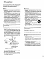
Precautions
Before using this umt please read these operating instructions
carefully. Take special care to follow the warnings indicated on
the unit itself as well as the safety suggeshons listed below.
Afterwards keep them handy for future reference.
Safety
Placement
1. Power Source -- The umt should be connected to power supply only of the type described in the operating instructions or
as marked on the unit.
1. Ventilation -- The unit should be s_tuated so that its location
or position does not interfere with its proper ventilation. Allow
10 cm (4") clearance from the rear of the unit.
2. Foreign Material -- Care should be taken so that objects do
not fall into and liquids are not spilled into the unit. Do not subject this unit to excessive smoke, dust, mechanical vibration,
or shock
2. Polarization -- If the unit is equipped with a polarized AC
power plug (a plug having one blade wider than the other),
that plug will fit into the AC outlet only one way. This is a safety feature If you are unable to insert the plug fully into the
outlet, try reversing the plug. If the plug should still fail to fit,
contact your electrician to replace your obsolete outlet. Do
not defeat the safety purpose of the polarized plug.
3. Power Cord Protection -- AC power supply cords should be
routed so that they are not likely to be walked on or pinched
by items placed upon or against them Never take hold of the
plug or cord If your hand is wet, and always grasp the plug
body when connecting or disconnecting
it.
4. Nonuse Periods -- When the unit is not used, turn the power
off When left unused for a long period of time, the unit should
be unplugged from the household AC outlet.
3.
Magnetism -- The unit should be situated away from equipment or devices that generate strong magnetism.
4. Stacking -- Do not place heavy objects, other than system
components, on top of the unit.
5. Surface -- Place the unit on a flat, level surface.
6. Carts and Stands -- The unit should be used only with a cart
or stand that is recommended
by the
manufacturer. The unit and cart combination
should be moved with care.
Quick stops, excessive force, and uneven
surfaces may cause the unit and cart combination to overturn.
7. Wall or Ceiling Mounting
Installation
-- The unit should not be mounted
to a wall or ceiling, unless specified in this operating instructions.
Environment
Maintenance
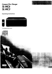
1. Outdoor Antenna Grounding -- If an outs,de antenna _sconnected to the receiver, be sure the antenna system is grounded so as to provide some protection against voltage surges
and built-up static charges. Section 810 of the National Electrical Code, ANSlINFPA No. 70-1990,
provides information
with respect to proper grounding of the mast and supporting
structure,
grounding
of the lead-in wire to an antenna
discharge
unit, size of grounding conductors,
location of
antenna-discharge
and requirements
below
unit, connection to grounding electrodes,
for the grounding electrode. See figure
Clean the cabinet, panel and controls with a soft cloth
moistened with mild detergent solution.
Do not use any type of abrasive pad, scouring
such as alcohol or benzine.
powder or solvent
Service
1.
ANTENNA
lightly
Damage Requiring Service -- The umt should be serviced by
qualified service personnel when:
(a) The AC power supply cord or the plug has been damaged,
or
LEAD IN
WIRE
CLAMP
(b) Objects have fallen or liquid has been spilled into the unit;
or
|
.ANTENNA
DISCHARGE
UNIT
(NEC SECTION 810-20)
3ONDUCTORS
810-21)
(c) The unit has been exposed to rain; or
(d) The unit does not appear to operate normally or exhibits a
marked change in performance; or
(e) The unit has been dropped, or the enclosure damaged.
2. Servicing -- The user should not attempt to service the unit
beyond that described in the operating instructions. All other
servicing should be referred to qualified service personnel.
POWER SERVICE GROUNDING
ELECTRODE SYSTEM
(NEC ART 250, PART H)
NEC-
NATIONAL
ELECTRICAL
CODE
2. Water and Moisture -- Do not use this unit near water - for example, near a bathtub, washbowl, swimming pool, or the like.
Damp basements should also be avoided.
3. Heat -- The unit should be situated away from heat sources
such as radiators and the like.
It also should not be placed in temperatures
(41° F) or greater than 35°C (95 ° F).
less than 5°C
3
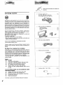
_iiiiiiiiiiiiii_ii_i_ii_iiiiiiL_iii_iiiiii;iiiiii!_!_!;!_!;!i!_!i!i!iiiii_iii_i_i_i_ii_!_iiii_iiiiiiiiiiiiiiiii_iiiii_iii_i_iii_i_ii_i_ii_
Please check and identify the supplied accessories
Listening
caution
[_
AC power supply cord
(For USA: SJA172-A or SJAr 72-1)
(For Canada: SJA172-A or SJA172)
[_
AM loop antenna set (RSA0010)
• AM loop antenna ........................
• AM antenna holder ......................
• Screw ..................................
1 pc.
1 pc.
1 pc.
[_
FM indoor antenna (SSA272) .................
1 pc.
_
Remote control transmitter
1 pc.
@
Selecting fine audio equipment such as the unit you've just purchased is only the start of your musical enjoyment. Now it's time
to consider how you can maximize the fun and excitement your
equipment
offers. This manufacturer
and the Electronic
Industries Association's Consumer Electronics Group want you to
get the most out of your equipment by playing it at a safe level.
One that lets the sound come through loud and clear without annoying blaring or distortion-and,
most importantly, without affecting your sensitive hearing.
Sound can be deceiving.
Over time your hearing "comfort
1 pc.
level"
adapts to higher volumes of sound. So what sounds "normal"
can actually be loud and harmful to your hearing.
Guard against this by setting your equipment at a safe level
BEFORE your hearing adapts.
To establish a safe level:
• Start your volume control at a low setting.
• Slowly increase the sound until you can hear it comfortably and
clearly, and without distortion.
Once you have established a comfortable
• Set the dial and leave it there.
sound level:
Taking a minute to do this now will help to prevent hearing
damage or loss in the future. After all, we want you listening for a
lifetime.
We Want You Listening
For A Lifetime
Used wisely, your new sound equipment will provide a lifetime of
fun and enjoyment. Since hearing damage from loud noise is
often undetectabte until it is too late, this manufacturer
and the
Electronic Industries Association's Consumer Electronics Group
recommend you avoid prolonged exposure to excessive noise.
This list of sound levels* is included for your protection.
*The level used here is different from that displayed on the
system's display.
Decibel
Level
30
40
50
60
70
80
(EUR643850)
Example
Quiet library, soft whispers
Living room, refrigerator, bedroom away from traffic
Light traffic, normal conversation, quiet office
Air conditioner at 20 feet, sewing machine
Vacuum cleaner, hair dryer, noisy restaurant
Average city traffic, garbage disposals, alarm clock at
two feet
Batteries
THE FOLLOWING
NOISES
CONSTANT EXPOSURE
90
100
120
140
180
BE DANGEROUS
UNDER
Subway, motorcycle, truck traffic, lawn mower
Garbage truck, chain saw, pneumatic drill
Rock band concert in front of speakers, thunderclap
Gunshot blast, jet plane
Rocket launching pad
Information
4
CAN
courtesy
of the Deafness
Research
Foundation.
(UM-4, "AAA",
R03) ...............
2 pcs.
/
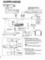
No.
Name
Re?. page
No.
Name
Re?. page
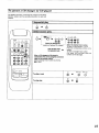
_) Power switch (POWER)
10
(_ Bass control (BASS)
11
_) Tuning buttons (TUNING)
13
_) Treble control (TREBLE)
11
(_) Band select button (BAND)
12
(_) Volume control (VOLUME)
10
_) FM mode select button
(FM AUTOIMONO)
(_) Headphone jack (PHONES)
11
12
_) Speaker select buttons (SPEAKERS)
10
(_) Memory button (MEMORY)
14
Direct tuning button
(DIRECT TUNING)
TapeNCR 21DCC monitor button
(TAPE/VCR 21DCC IMONITOR] )
10,16
12
Input select
(_ Numeric buttons (1 - 0)
12,15
Muting button (MUTING)
11
buttons
_) Balance control (BALANCE)
10
11
5
I White
Stereo (L)_
connection
Red
(R)
cable (not included)
IC_
I
Tape deck, second VCR (audio line only) or digital compact cassette deck
(DCC) (not included)
CD changer (or CD player)
(not included)
REC (IN)
i
i
I
t
OUTPUT
AC power cord
(included)
Household
AC outlet
Only for turntable
with ground terminal
(AC 120 V/60 Hz)
\
Connect this
cord after all
other cables
and cords are
connected.
REMOTE
CONTROL
OU]
I
Antenna
terminals
i_
A_,
I"v
At.. OtJlL[]
Speaker terminals
See page 9.
_b
TV (not included)
J
See pages 7-8.
YOUTPUT
/
/
/
"_L Turntable
GND
/""/
,
.
r
/-_--_
_
/
ANUDIO
I IAUDIO
OUT
IN
VIDEO
VIDEO I
OUT
[(not included)
_
I°_°°"°_"
I
VCR (not included)
[]
I
REMOTE
CONTROL
i
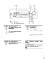
This unit
"REMOTE
CONTROL
Connect
connection
the
OUT" terminal
cable
for remote
control
to a
Technics tape deck andlor CD changer (or CD player) which
has the appropriate remote control terminal as shown at the
left.
If a tape deck is not being used, the CD changer (or CD
player) can be connected directly (dotted line).
For a tape deck and/or CD changer (or CD player) with a
remote control sensor, this connection is not necessary.
Connection
cable for
remote control
(not included)
_-_ "SWITCHED"
cord
(not included)
(or CD player)
I CD changer
(not included)
AC outlet
Power to the outlet is controlled by the power switch of this
unit Audio equipment rated up to the indicated power
ratings can be connected here.
For proper remote.control
operation
Connect the power cords of the tape deck and CD changer
(or CD player) as shown at the left.
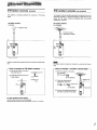
FM indoor
This antenna
casts.
antenna
is normally
sufficient
i.cl. ed)
for reception
_FM outdoor
of FM broad-
The outdoor antenna should be used when using the main unit in
mountainous areas or in spaces enclosed by reinforced concrete
where the FM indoor antenna (included) does not provide
satisfactory
reception.
FM Indoor antenna
FM outdoor antenna
(included)
(not included)
/"-_,,--
Adhesive
.ot i,,cl.dem
antenna
tape
75-ohms coaxial
included)
Attach to a wall (using a tape) facing in the direction of best reception.
--How
to connect an FM indoor
antenna--
(_ Pull off the plastic on the tip of
the antenna wire.
ZZ:E],,--1_EE:_Z_ --_
(_ Twist the wire and connect as
shown below.
_"
--_'_"_
Twist
An outdoor antenna
only.
--How
should be installed
by a qualified
technician
to connect a 75-ohms coaxial cable--
(_ Remove a piece of the outer
vinyl insulator.
20 mm (25132")
Shield braid
(_ Twist the shield braid to
expose the core wire.
wire
q_).__
q_l__,,,_
Core wire
10 mm (3/8")
wire
(_ Connect the shield braid and the
core wire as shown at the right.
For best reception sound quality:
An FM outdoor antenna is recommended.
Disconnect the antenna if an FM outdoor antenna is installed.
?
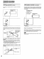
AM
loop
This antenna
casts.
antenna
is normally
AM
J.cl.ded)
sufficient
for reception
of AM broad-
outdoor
antenna
The outdoor antenna should be used when using the main unit in
mountainous areas or in spaces enclosed by reinforced concrete
where the AM loop antenna (included) does not provide satisfactory reception.
AM loop antenna
(included)
AM outdoor antenna
(not included)
Vinyl-covered wire
(not included)
AM ANT
AM loop antenna
(included)
AM AI_
AM LOOPANT
AM LOOPANT
L.
(noti.eJ.d )
,.J
Install the AM antenna holder (included) at the rear panel of this
unit and then attach the AM loop antenna to the AM antenna
holder.
Insert the tab into
the hole and then
Use 5- 12 m (16-40
ft.) of vinyl-covered
window, or convenient location.
wire horizontally
at the
When the unit is not in use, disconnect the outdoor antenna to
prevent possible damage that may be caused by lightning. Never
use an outdoor antenna during an electrical storm.
push the holder
Rear
of this unit
Be sure to connect the AM loop antenna even when an outdoor
antenna is used.
AM antenna holder
(included)
Pay attention
to the following points when mounting the
antenna.
• Do not mount it horizontally (Doing so will impair reception).
• Do not mount it close to power cords, speaker wires or metal
surfaces (Doing so will result in noise).
• Do not mount it close to a tape deck. When the tape deck is being used, chirping or beeping sounds may result.
When mounting
or rack
the antenna to a column, a wall
antenna
holder
(included)
Screw (included)
8
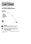
Right
speaker Leftspeaker
(not included)
1
,i,Twist
3
2
15 mm
(not included)
j
m!
To prevent damage to circuitry,
never short-circuit positive (+) and
negative (-) speaker wires.
• "B" terminals
For connection
to a second pair of speakers.
•Speakerimpedance
The impedance
ohms.
of any speaker
used with this unit must be 8
9
]
3
2
5
I o
'.'':
......
O
0
O-
,,.c_a
©
__J
L__
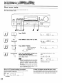
POWER
Before operation,
VOLUME
TAPE/VCR 21DCC
set VOLUME to the "0"
position.
..... _WER..... Press PovvER
Start the desired source.
to Switch on
(Refer to the appropriate
structions for details.)
the power.
_
S_AKE_ .... Press A and/or
('_
Bt0
the speaker system(s) to be
_J
used.
_
VOLU'ME
........ Turn voLUME
A and B reler to the speaker terminals
at the rear of the unit.
FM
I_1
IIII I__1, I I
in-
Select
A
_"''_
operating
to adjust
the
volume level.
..,
Illuminates
If the button is pressed once more, the
indicator will switch off and no sound
will be heard from the speakers.
__PreSS
_
_
\
_>
After listening is finished
Be sure to reduce the volume level, and switch the power to the
standby condition by pressing POWER.
tO seiecithe desirea
source.
/
VCR 1: TO listen to video tapes (VCR 1)
TAPFJVCR
_OCC
_
: To listen to tape, video
tapes (VCR 2) or digital
compact cassette (DCC).
The
tape monitor
indicator will appear.
(See below.)
CD: To listen to compact discs
TUNER: To listen to radio broadcasts
PHONO: To listen to phono discs
When tape monitor indicator
fleshing (approx. 3 seconds)
illuminates
or is
This indicates that the tape monitor function of this unit is ON.
To listen to sources other than a tape, VCR 2 or DCC, be sure to
turn off the indicator by pressing TAPENCR 21DCC _.
Illuminates
FM
LI/_1
/._1
/ I,
I/
._
or _lashing
SPEAKERS
MUTING
VOLUME
©
t
I
J
I
tJ ....J
i
I-1
TM
......
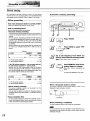
1-BALANCE
BASS
Headphones (not included)
Plug type:
1/4 inch phone plug stereo type
To adjust
BASS
Q_
the
tone
quency
To mute
quality
Turn BASS to adjust
©
the Iow-fro-
(3
TREBLE
©
the sound
MUTING
Press MUTING.
sound.
FM
TREBLE
©
level
I II
I,
I
MHz MLITING
flashing
Turn TREBLE to adjust the high.fre.
quency sound.
Press once again to return to the previous
volume level. (The muting indicator will turn
off.)
To
adjust
the
_LANCE
Turn
sound
balance
BALANCE
to
adjust
leftlright sound balance.
the
When
phones
listening
through
Use VOLUME to reduce the volume
connect the headphones.
headlevel, and
If sound from speakers is not wanted, press SPEAKERS (A)
and/or (B) to turn off the speaker select indicators.
j v_?/;J'FJ.
Avoid listening for prolonged periods of time to prevent hearing
damage.
11
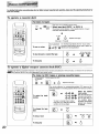
Direct
access
tuning
Specify the frequency using the numeric
to the desired broadcast station.
buttons
to directly tune
0
!r-q
I ........
5
i _ ....
66
!,I,;0,
1
I
!:
C)L_____J'
2 AUTO/MONO
FM 3
Press TUNER.
TUNER
L
BANO J
Press BAND to select "FM"
or "AM".
_
T
IIII
I
I._1I._l,
I
..,
III1,11
I I I
I
...
Illuminates
DIRECT
TUNING
[_
Press DIRECT TUNING.
........................................................................................................................
[.
^
While' cursor display is
flashing (approx. 10
J
"_
Press the appropriate numeric
tons to enter the frequency.
but-
If the frequency has been input correctly, the frequency display will blink.
1. If no button is pressed while the cursor display
is flashing, the display will return to the frequency which is currently being received. To respecify the frequency, repeat the procedure
from step 3.
2. If the frequency has not been input correctly,
an error message will be displayed. In this
case, re-enter the frequency.
When the FM stereo broadcast
is received:
This unit will automatically switch to FM stereo reception and the
FM stereo indicator will illuminate.
--
--
[QEI
FM
/1\_---I/
M,=
If the desired
MHz
[]
"-'* []
LOCK
(33
rM
r QUARTZ
Ium
FM frequency
"-* []
is 107.9
-_ []
II II
I I._1
I I__I
I, _1
MHz
nates when tuned
If noise is excessive in the FM stereo mode
Press FM AUTO/MONO. (The FM stereo indicator will switch off.)
The broadcast will be monaural, but noise will be reduced. If the
button is pressed once more, stereo mode will be resumed.
OUARTZ
STiREO
Illuminates
12
--
,__conds)
i-TI3-1_c_]
L_K
[--
I' I._1
I,' _1
'
' I
I. I
..=
Sequential
If the frequency
ching.
tuning
is not known, use the tuning control
for sear-
....
0
5b
_B
©
I -, I_1 .... l_I _
t__.__j'
_2
"-t
,.,
2
TUNER
p,
I 'r°'"
[
gO
%
L
BAND
Press BAN D to select "FM" or "AM",
I
[
gO
FM
I II
I II
iM
I_lllllll_ll
I
I,
I
I
MS,
I
MHz
!
!
Illuminates
r
/
v
TUNING
^
n
-,,
-
Press V or A to tune to the desired
_-_.,z--
_____
I_
/J
oroaacasz,
lgO
II I
_
.
Tuning intervals
FM: 200 kHz interval
AM: 10 kHz interval
I Lock STEREO II
F,
II
--
I I I
I "-I
' --
--
I
,.,
If either button is pressed and held down until the
frequency begins to change, the broadcast stations can be tuned automatically
when a broadcast station is found.
Tuning may stop automatically
encountered.
if any jamming
is
13
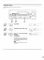
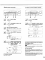
Preset
tuning
By presetting the desired broadcast stations into the memory
channels of this unit, broadcast stations can be selected simply
by pressing numeric button(s). (Refer to page 15 for tuning.)
-Before
Automatic
memory
presetting
J
presetting
How many broadcast stations can be preset?
A total of 30 FM and AM stations can be preset.
How is presetting
done?
The two following methods are available.
• Automatic
memory
presetting
Automatic memory presetting allows this unit to automatically search for broadcast stations and then preset them into
memory.
With this function, searching proceeds from the frequency
currently being displayed and continues through higher frequencies, (up to 107.9 MHz for FM, up to 1710 kHz for AM)
and broadcast stations are preset in the order in which they
are located.
Press TUNER.
With this method, the channel ranges that can be preset into
the memory for different bands (FM or AM) are set as
follows.
....... e'_'N'D
..... Press BAN Dto
L
Channel
_
FM
For FM broadcast
For AM broadcast
stations ........................
stations .......................
seiect ,_FM ;,
_l
3_
'settothe
whichpresetyou
want to startfrequency
automatic from
memory
ting. (Follow steps 3 and 4 on page 12.)
1-30
21 -30
If the FM stations (channels 1-30) are preset and then
the AM stations (channels 21 -30) are preset:
Because this unit can accommodate
a total of 30 preset
channels, the settings for FM channels 21-30 will be replaced by the AM settings which were subsequently preset, and
the channel allotment will be as shown below.
..... "E_:;R_.... Press MEMoRYontiithe
ire.
[
_
j quency begins to change.
'_'k_-"
(Automatic
memory
presetting
will
start.)
To stop press MEMORY once again.
Channel
For FM broadcast
For AM broadcast
stations ........................
stations .......................
1-20
21-30
When a broadcast
• Manual
memory
presetting
The desired broadcast stations can be preset
desired channels by the user.
This can also be used as a method for changing
broadcast stations that were preset in "Automatic
presetting".
into the
selected
memory
channel
number
will be
MEMORY
r-_
Please remember this:
If a new broadcast station is preset into a channel, the setting for the broadcast station which was previously entered
in that channel will be automatically erased.
station is preset
The memory indicator and the preset
displayed for approximately 1 second.
I
i
L_/
/
I
II
I
-
I
Illumi!ates
When presetting
The last broadcast
is completed
station to be preset will be displayed.
e errJ
Correct presetting may not be possible in cases where.the broadcast waves are too strong or too weak. In such cases, carry out
presetting manually.
14
Manual
memory
presetting
To listen
660
5
db
rlm]W
Io-
I
24
_
to preset
5
d-o[
-I='1
2
Q-
1
[
.................
Press BAND to select "FM"
I__
_JI11213
";"Tu"E":
...............
........ SpecifY ihe preset channel
I\ 9_L__gJusing the numeric button(s).
(Example: Channel 12)
[]
Set to the desirod
br0adcast.
i
_'
L_ I
i
I_'1-1
'L___J
" _'Press'TuNERI
[ 3
stations
_-_--_E_I
I 6(3.
_1::_::___
i_ .....................
15
BANV
broadcast
(Within 2 sec.)
=%
............
(FOllow steps 3 and 4 on page 12 or step 3 on page
13.)
You can also set the stereo mode to the monaural
position.
I I
LI-- t-I
.... M'E"
"MORY
..... Press M E M0 RY m0mentari.
I
1 I
L t_
I \_/
I/1_
I
I
IIZ
QUARTZ
Illuminates
I
K"TZsTE,EOII
FM
I!
I /._1
•OCK S_.EO // // / /._/
I LI
I. _1
I /.__1
/, __1
,.,
To cancel the memory function,
MEMORY again.
_._l-Tl-_-_...............
press
Specify ihe desi;ed channei
_to
be preset
using the
numeric
button(s)
(completes presetting).
To confirm the channel number of the broadcast
station being received
(Example: Channel
(The channel number
[]
MEMORY
Off
(Within
I /._1
/_-- I I
12)
2 sec.)
I\l_/
I/1\
Preset channel
,._1_.
r'_
"---'=
I
I._
II-- II_I
II_I--I
_ []
Press TUNER.
will be displayed
presetting
Repeat steps 2 through
5.
for about one second.)
J_r
The channel number is not displayed
frequency or FM mode setting.
if you change the reception
For your reference:
Even it the power is switched to the standby condition or the
power cord is disconnected
from the household AC outlet, the
contents of the memory
imately one month.
will continue to be stored for approx-
If frequency presettlngs
To continue
,,,
are accidentally
erased
Make the frequency presettings once again.
The power cord should remain connected for one hour or more
for the memory back-up to be effective.
15
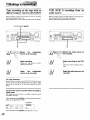
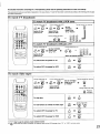
Tape recording
digital
compact
on the
cassette
tape deck or
deck (DCC)
Before recording, prepare the tape deck or DCC for recording
(recording level adjustment, etc.).
See the tape deck's or DCC's operating instructions for details.
VCR. (VCR
audio source
1) recording
from
an
Before recording, prepare the VCR (VCR1) for recording
ding level adjustment, input selector setting, etc.).
See the VCR's operating instructions for details.
(recor-
TAPENCR 21DCC
J
I°0
_;
(5-o [_[-I_
I _ I-l
II
O.L_____J
'L.____J
L_____J"
1
1
]___S...€,
.....ih;....,U;_.oivid;0
S;;,ect
t"e;..d,oSo"roe
io
source to be recorded.
be recorded.
_'
................
Begin recordingl ..............
Follow your tape deck's
operating instructions.
or
DCC's
For your reference
to the TAPE/VCR 2/DCC
terminals
on
the rear of this unit, sound recording from an audio or video
source can be carried out by the same procedure as given
above.
To check the sound recorded while recording is
being made
With a tape deck with 3 heads, it is possible to check the sound
recorded on the tape.
Press TAPENCR 2/DCC _
on this unit and set the monitor
button on the tape deck to "TAPE".
Illuminates
QUARTZ
LOCK S_E_eO
(_
FM
II
II
I/._1
Press TAPENCR 2/DCC _
16
I /__1
_ __1
Begin recoiding
1.
on the VCR
Follow your VCR's operating
tions.
Begin
the
audiolvideo
source to be recorded.
When a VCR is connected
................
MH,
once again to turn it off.
instruc-
................
aeoin;he"udiosouice
tobe
recorded.
,ilililililiiii_ii,
i,_i,
_iiiiiiiiiiiil
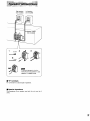
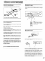
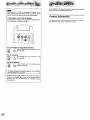
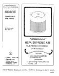
Battery
installation
Insert the batteries
Method
included with this unit as shown below.
for
use
Use the remote control within 60 degrees and within 7 meters (23
ft.) facing directly toward the receiver's remote control signal
receptor.
J
.................,.,
[_
T ......'..
Check the (+)
1-) sides.
When
you need
to replace
Use two UM-4 "AAA",
Use
these
batteries
IEC R03 (1.5 V) or equivalent
batteries.
About 7 meters in front of the
sensor
(The actual range will depend on
the angle at which the remote
control is used.)
of batteries
Do not mix old and new batteries,
(carbon and alkaline, etc.).
or batteries
of different
Always remove old, weak or worn-out batteries
dispose of them properly.
The battery
promptly
types
and
life is about one year.
Although the battery life varies depending on how often the
device is used, the batteries should be replaced about once
every year on the average.
Operation
notes
The batteries should be replaced if commands from the remote
control transmitter do not operate the unit even when transmitter
is held close to the front panel.
Never subject batteries
tempt to disassemble
cuited.
to excessive
heat or flame; do not at-
them; and be sure they are not short-cir-
If the remote control is not to be used for a long period of time,
remove the batteries and store them in a cool, dark place.
Aim the remote control's
transmission
window toward the unit's
sensor. Avoid any obstacles.
If a battery leaks, remove all batteries and dispose of them properly. Thoroughly clean the battery compartment
before inserting new batteries.
If the electrolyte comes into contact with skin or clothes, flush
with water immediately.
Keep batteries
l ==lsoOl
_°oo°o
_t/t
o
t
t t i°1_
out of reach of children.
Do not use rechargeable
(nickel-cadmium)
Do not attempt to recharge
type batteries.
alkaline or carbon batteries.
Avoid dust
Be sure the transmission
Avoid dust
window and the unit's sensor are free
from dust. Excessive dust might affect performance.
The operation may not be correct if direct sunlight or another
strong light source strikes the receiving sensor of this unit. If
there
is a problem,
place the unit away from the light source.
When operating a TV, VCR, digital compact cassette deck
(DCC) or a CD changer (or CD player) with a remote control
sensor, face this remote control toward the remote control
sensor of the unit to be operated.
]7
i!_!_!i!i!'!ii!i!iiiiiiiiiiiiiiiiiiiiiiill
_!i __iiiiiiiii
_iiiiiiiiiiiiiiiiiiiiiiii!ii!ii!!iL_
__i_i iiiiiiiii!!ii!iiiiii!iii
!iiii
Remote
_
This remote control transmitter can be used to operate otl'ier
units manufactured
by this company in addition to this receiver
If a tape deck andlor CD changer (or CD player) has the appropriate remote control terminal, be sure to connect the connection cables for the remote control as shown on page 6.
unit, including TVs and VCRs manufactured
since 1985, CD
changers (or CD players), tape decks and DCC decks.
Preparations
before use
Connect the power cords of a CD changer
(or CD player) and a
tape deck as shown on page 6.
If the connections are made and the power supply switches of
each unit are set to ON, the power supply for each unit will
simultaneously
turn ON and OFF when the power supply of the
receiver is turned ON and OFF.
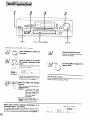
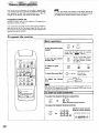
To operate
the receiver
Basic operations
POWER
TUNER
o
To turn the power supply
ONIOFF
f
I
POWER
TV
VCR
TUNER
CO
I Occ
©oo
©©@
VCR
1
TAPE
••/F
SKIP <1/4•
CH
0
_
r-TVNCR
0
4
_
--
TUNER
CD
o
]
VCR 1
@
®
Press once more to
To mute
the sound
level
_
MUTING
return to the
original volume.
•
CD'"
5
6
__10
8
9
0
--
To
adjust
the
VOLUME
+
volume
level
I
@
©
•
__0
7
To turn off the tape monitor
function, press one of the input select buttons (TUNER,
CD, VCR 1).
TAPE
To turn the tape monitor
function ON
]
o 0"'0 IO
V
Once the power has been set to ON, it can be
turned ON and OFF simply by pressing
POWER. (See
gg_
below.)
To select an Input
source
0000
<HI/RSKIP
'* @
MUTING
1
After carrying out the operation on page 21 for turning the power of the TV or
VCR ON or OFF, always press TUNER before pressing POWER when turning
the power of the receiver ON and OFF.
To listen to radio broadcasts
To select the desired channel sequentialy
L
vCH^
J
TUNER
©
@Q
Select the
desired
preset channel.
To select the desired channel directly
1
TUNER
_
4
7
2
_
5
8
Specify the preset channel
using the numeric button(s).
3
_
6
9
_"(Example:
Channel 12) _
0
1
2
Within 2 sec.
18
,
a CD changer
To operate
(or CD player)
For detailed information concerning CD changer (or CD player)
operation, please read the operating instructions
for each unit
carefully.
Sequential
play
CD
©
Direct
),
-_ Q
access
play
1
CD
_/DECK
O
Q-l,
r
POWER
TV
VCR
CD
II_
1
2
3
_/DECK
7
8
9
0
-
7
MUTING
8
9
0
disc.
(only for a Technics CD changer)
Play will start from
the selected track.
OQ
3
5
_DCC
/R.SKIP IHIz'/F.SKIP _/<lll_
2
3
o_o
Select the desired
TAPE
2
GO
00@
@
0
-I,
1
4
TUNER
Oooo
MCR 1
112
_m
When a CD changer (or CD player) Is
connected to this unit by using the connection
cable for the remote control:
Select the desired track number.
To select a track between 1 and 9:
Press the corresponding number on the
keypad.
To select a two-digit track number:
First press >10, and then press the
numbers for the two digits.
Select a two-digit track number by pressing
I_I_/F.SKIP.
1
CD
To skip a track
@ "_
_1<1/R.SKIP
Q
I_I_/F.SKIP
0
To stop play
19
For detailed
Information
concerning
tape deck or digital compact
cassette
deck operation,
please
read the ol)eretlng
Instructions
for
each unit carefully.
o
To operate
a cassette
deck
To listen to tapes
Only when using a double cassette
TAPE
f
FC_ER
W
_)/DECK
1/2
deck
Select tape deck (DECK 1 or DECK 2)
The remote control indicator of the cassette deck is changed
TUNER "_
over each time the button is pressed.
0o_@!
©co
vcn i
_
_lP
T_pI:
_
cD
4/4k
k
e_eo
,
_
3
_ECK
4
_
S
2m
0000
66
c:bcb
•
@
Q
(Reverse)
(Forward)
During playback
TAPE
To cue or review
(o ......
4/41_
_)
/
Playback will begin.
For Technics tape decks with the "music
._,.SK,P="_.S_J uncti°ns'
m), O
O
desired
these buttons
tune during playback.
TAPE
To fast-forward
\
J
To operate
a digital
or rewind the tape
In the stop mode
Q
4<1/R.SKIP
-,
@
TAPE
compact
cassette
deck
I_ll,/F.SKIP
@
•
©
To stop play
select"
can be used to select the
,,
@
(DCC)
The explanation below is an example of operation in the case where a DCC has been connected to the "TAPENCR 21DCC" terminals on the rear of this unit.
The Technics RS-DC10 can not be operated by this remote control.
To listen to DCC tapes
VCR I
Facing toward the DCC
TAPE
_
ml_
TAPE
Ooo_
OeO
_
®_ee
To select
number
__(D
by
track
_
8
cassette
tapes
Playback will begin.
This is only effective for commercially-available
DCC tapes and for
other DCC tapes for recording purposes which have had track numbers
recorded.
Select
the desired
1
2
3
track number.
After the desired track
7
8
9
'_
oogl
5
or analog
Facing toward
the receiver
i
To select a two-digit track number:
First press > 10, and then press the
numbers for the two digits.
/
'1o...... /
To change
side
the tape
0
has been searched for,
the unit will return to
the condition before
the button was pressed
(playing back, stopped
or paused).
©
4 / 41k"
441
To skip a track
To stop play
20
0
/R.SKIP
©
I_ I_ IF.SKIP
©
For detailed
information
concemlng
The explanations below are examples
6 of these instructions.
To watch
TV
TV or VCR operation,
please
read the operetlng
instructions
for each unit carefully.
of operation in the case where a TV and VCR have been connected
according
to the method given on page
broadcasts
To watch
TV broadcasts
Facing toward the TV
POWER
TM
F
with a VCR tuner
Facing toward the receiver
Facing toward the VCR
POWER
MCR
Switch ON the
Switch ON the
power for TV.
power for VCR.
Set the
TVIVIOEO
mode on the
TV to "VIDEO".
VCR 1
-_
1
2
3
4
5
6
7
8
9
©
Facing toward the VCR
vCH
^
@@
O000
,o.e._._l16
Select the desired
To watch
TV broadcasts
or
with just a TV
Facing toward the TV
TV
_
[© ......
POWER
_
_
1
0
channel.
Facing toward the TV
1
2
3
7
8
9
Set the TVIVIDEO
mode on the
m_
TV to "TV".
0
Switch ON the
Select the desired
power for TV.
TV
\
/
POWER
To switch OFF the power for TV
POWER
VCR
•, @
To switch OFF the power for VCR
To watch
video
tapes
Facing toward the TV
"IV
POWER
TV
Facing toward the receiver
Facing toward the VCR
VCR
Set the TVIVIDEO
mode on the TV
to "VIDEO".
POWER
f
_ER
channel.
VCR 1
-_ @
TUN_
®'o6
Switch ON the
Switch ON the
power for TV.
power for VCR.
Facing toward the VCR
oeoe
o o"'®lie •
_
VCR
© c5 c_ 85
6cb_
*
To stop play
[0 ......
]
or rewind
the video
•
©
In the stop mode
VCR
To fast-forward
Playback
will begin.
tape
I_
44/R.SKIP
I_I_/F.SKIP
@ @
POWER
TV
J
\
/
To switch
OFF
the
power
for TV
To switch
OFF
the
power
for VCR
VCR
r--TV/VCR How to use the antenna Input selection button
ANT_
Each time the button is pressed, the antenna input at the VCR changes
from "TV" to "VCR"
-,@
-, @
POWER
and vice versa.
21
Do notattempt to removethe cover(s)or repair the unityourself.
Refer servicingto qualified personnelonly.
Bm"=!
If you operate a TV, VCR or alternative CD changer (or CD
player) using this remote control, the unit may fail to operate
due to the differing nature of the remote control signal.
If the remote
control
falls
It is necessary to reprogram the signal within the remote control by following this simple procedure.
VCR
!
000
POWER
TAPE
CD
TV
VCR
TUNER
For CD changer (or CD player) operation
POWER
CD Press POWERand CD simultaneously,hold
for 2 seconds.
For TV operation
POWER
TV
Press POWER and TV simultaneously,
hold
for 2 seconds.
For VCR
POWER
operation
VCR Press
O
POWER and
VCR simultaneously,
hold for 2 seconds.
To restore the previous memory
same operations one more time.
contents,
carry
out the
Depending on ihe model, there may be cases where operation is still not possible even if the remote control signal is
switched
over due to differences
in frequency
range
characteristics.
22
Product
information
to operate:
For product service, product information or assistance
duct operation, refer to the servicenter directory.
with pro-
Before requesting service for this unit, check the chart below for
a possible cause of the problem you are experiencing. Some simple checks or a minor adjustment on your part may eliminate the
problem and restore proper operation.
If you are in doubt about some of the check points, or if the
remedies indicated in the chart do not solve the problem, refer to
the directory of authorized service centers (enclosed with this
unit) to locate a convenient
service center, (_'r consult your
Technics dealer for instructions.
(In U.S.A. consult
structions.)
I
Problem
While
Probable cause(s)
listening
Noise Is excessive in both
stereo and monaural broadcasts.
Poor location and/or direction
The FM stereo indicator
Poor location and/or direction
or
Transmitting
station
Transmitting
Excessive distortion in the
sound of stereo broadcasts.
Nearby building or mountain.
listening
sound
noted
Power will not switch
remedy
I
• Try reducing the treble sound by using the treble control.
• Try changing
the antenna.
the location, height andlor direction
• If an indoor antenna is being used, change
outdoor antenna.
of
to an
• Try using an antenna with more elements.
of the antenna.
station is too far away.
• Try changing
the antenna.
the location,
height and/or direction
• If an indoor antenna is being used, change
outdoor antenna.
of
to an
• Try using an antenna with more elements.
Unit is being used at the same time as the
television set.
• Turn off the television set, or use this unit farther
Interference
• Try reducing the treble sound by using the treble control.
from adjacent
broadcast
The AM loop antenna connection
close to the power cord.
signal.
wires are too
away from it.
• Place the antenna connection
cord farther apart.
The power supply frequency from the power cord
is modulated and heard from the speakers.
• Install a special
Caused by the "discharge
• Try placing this unit farther
ment.
phenomenon"
and the
"oscillation
phenomenon"
of electric appliances
(such as fluorescent lights, TV, small series-type
motors, rectification
equipment, etc.).
wires and the power
outdoor antenna.
• Install noise-prevention
the electric appliance.
away from such equip-
equipment
on this unit or on
at all times
ON.
No sound is heard when the
power is switched
in-
to AM broadcasts
sound is
A strange hissing noise is
produced continuously or
Intermittently.
Problems
of the antenna.
is too far away.
the quartz lock indicator
flickers, without completely
illuminating.
A low-pitched "hum"
is heard when the
broadcast is tuned.
for detailed
to FM broadcasts
A slight noise may be heard because the method
used for modulation of FM stereo broadcasts is
different than that used for monaural broadcasts.
An unusual "beat"
heard.
Servicenters
Suggested
An unusual hissing noise is
heard when listening to the
broadcast in stereo, but not
heard when listening
monaurally.
While
MSC Authorized
ON.
The power cord plug is not completely
inserted.
Connections are incomplete
speaker systems, etc.
or incorrect
The incorrect
has been pressed.
input selector
to the
• Confirm that the power cord plug is connected
completely.
• Check to be sure that all connection
correctly
wires are
connected.
• Check to be sure that the correct
selector
is
pressed.
The speaker select indicators
Sound stops during a
performance, or no sound
Is heard when the power is
switched ON.
(The word "OVERLOAD"
appears on the display.)
Remote control transmitter
does not function,
are turned off.
• Turn on the speaker select indicator(s).
The protection circuitry has functioned because
the positive and negative speaker connection
wires are "shorted",
speaker systems with an
impedance less than the indicated rated
impedance of this unit are used or under severe
use, such as loud volume, excessive power and in
an excessively hot environment.
• Switch off the power, and after determining and
correcting the cause, switch on the power once
again.
• Use a speaker system of the proper impedance
rating.
Batteries
• Insert the batteries so that the positive (+)
negative (-) polarities are correct.
are incorrectly
installed.
The remote control transmitter batteries are
drained.
• Replace them with new batteries.
There is an obstruction between the remote
• Remove the obstruction.
control transmitter
and
and the receiver, TV or VCR.
The remote control transmitter is not correctly
facing the receiver, TV or VCR.
• Face the remote control transmitter correctly toward
the signal receptor of each unit.
23
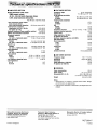
•
AMPLIFIER
Rated
SECTION
minimum
•
sine wave
Frequency
Sensitivity
RMS power output
40 Hz-20
kHz both channels
driven
0.8% total harmonic
distortion
100 W per channel (8 Q)
1 kHz continuous power output
both channels driven
0.8% total harmonic distortion
103 W per channel(8 Q)
Total harmonic distortion
rated power at 40 Hz-20 kHz
0.8% (8 _)
half power at 1 kHz
0.07% (8 L3)
Dynamic headroom (Power amplifier section)
2 dB (8 Q)
SMPTE intermodulation distortion
0.5% (8 _)
Frequency response
PHONO
RIAA standard curve +0.8 dB
CD, VCR 1, TAPE/VCR 21DCC
10 Hz-70 kHz, +3 dB
Input sensitivity
PHONO
CD, VCR 1, TAPENCR
SIN (IHF, A)
PHONO
CD, VCR 1, TAPE/VCR
Input Impedance
PHONO
CD, VCR 1, TAPEIVCR
Tone controls
BASS
TREBLE
Low frequency damping
Load impedance
AorB
A and B
2/DCC
0.4 mV (3 mY, IHF '66)
27 mV (200 mV, IHF '66)
2/DCC
68 dB (71 dB, IHF '66)
70 dB (85 dB, IHF '66)
47 k_
2/DCC
factor
FM TUNER
SECTION
range
87.9-107.9
M Hz
11.2 dBf (2 HV, IHF '58)
50 dB quieting sensitivity
MONO
STEREO
Total harmonic distortion
MONO
STEREO
SIN
MONO
STEREO
18.3 dBf (4.5 HV, IHF '58)
38.3 dBf (45 IJV, IHF '58)
0.2%
O.3%
75 dB
7O dB
Frequency response
20 Hz-15
Alternate channel selectivity
Capture ratio
Image rejection at 98 MHz
IF rejection at 98 MHz
Spurious response rejection at 98 MHz
AM suppression
Stereo separation
1 kHz
10 kHz
Carrier leak
19 kHz
38 kHz
Antenna
terminal
kHz, +1 dB, -2
65
1
45
80
75
50
dB
dB
dB
dB
dB
dB
dB
40 dB
30 dB
-35
-50
dB
dB
75 Q (unbalanced)
22 kQ
50 Hz, +10 dB to -10 dB
20 kHz, +10 dB to -10 dB
30 (8 Q)
8_
8
•
AM TUNER
SECTION
Frequency range
Sensitivity
Selectivity
Image rejection at 1000 kHz
IF rejection at 1000 kHz
•
530-1710
kHz
20 IJV, 330 pV/m
55 dB
40 dB
60 dB
GENERAL
160 W
Power consumption
Power supply
Dimensions (W x H x D)
AC 120V, 60Hz
430 x 136 x 305 mm
(16-15116" x 5-11132" x 12")
6.6 kg (14.5 lb.)
Weight
Notes:
1. Specifications
are subject to change
and dimensions are approximate.
2. Total harmonic distortion is measured
analyzer.
Matsushita Consumer Electronics
Company, Division of Matsushita
Electric Corporation of America
One Panasonic Way Secaucus,
New Jersey 07094
Printed in Singapore
Panasonic Sales Company,
Division of Matsushita Electric of
Puerto Rico, Inc. ("PSC")
Ave. 65 de Infanteria. Km. 9.5
San Gabriel Industrial
Puerto Rico 00985
Matsushita
without notice.
Weight
by the digital spectrum
Electric of Canada
Limited
5770 Ambler Drive, Mississauga,
Ontario L4W 2T3
Park, Carolina,
RQT2694-P
H 1094J0