1
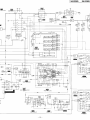
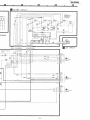
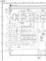
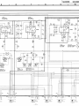
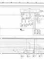
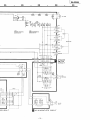
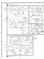
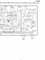
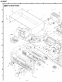
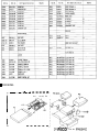
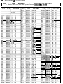
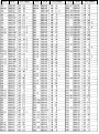
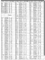
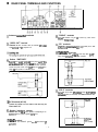
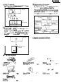
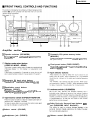
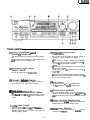
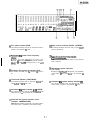
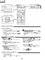
WI415
sJs9233A
ICCasllEr
Ccm
II
I
I
I
I
wo xu.
VU301
NNDxAMoEi3 V. R RI I
VRYll
bWJTF25BlS V. R MIN WLIME
ww2
NJLxsm1GIs v. rl WC2
WI1
NWQ2Q22240 V. R CENTER FREM
I PACKING
rI
_ _
_- _-----A4
AI-A3, P4
1
I
F.B.Ass’y
s2
I
I
I
I
I
I
I
I
L
__---(P2 @ @ 0 0 : Part No. RPN0324-21
n
RESISTORS & CAPACITORS
Wotes : l Capacity valuse are in microfarads (uF) unless specified other.ise.P=Pico~farads(pF) F=Farads(F)
l Resistance values are in ohms. unless specified otherwise, lK=l. OOO(OW) , lY=l. 000k@lM01)
RlD7
ERC62TJ103
RlD8
IERDSTJ151
1 l/d!?
1,4W
1OOK
1/4w
68
1,4W
2.7K
1/4w
33
1,4W
56
1/4w
68
1,4w
33
1,4W
56
1/W
47K
1,4W
2.7K
IRzll
/ERDSZTJ222
AZ12
~ERDSZTJ153
1 1,4W
1,4w
iOK
R213
iERDSZTJ104
'5K
1 1/4W
1,4W
47K
1
1/4W
2.2K
h367.368 1ERDSZTJ272T
1,4W
iK
1,4w
10K
,,4W
3.3K
1/4W
82K
1,4W
47-
1,4W
1K
1NW
2.2K
R603.604
ERL62TJ563
1,4W
56K
R605.606
ERDSZTJ182
1,4W
1.8K
R601.608
ERDSZTJ663
1,4W
66K
ERC62TJ470
1,4w
47
47K A
R616m618
1,4w
ERC62TJ473
1,4w
ERESlFVJZZlT
I/Z+
ERG2ANJP331S
2.t
330
ERDSZTJ684
1,4w
680K
ERNFVJMT
1mV
180
_
mi
._~,
A
Printed in Japan
H910503570 NHIYUITN
n REAR PANEL TERMINALS AND FUNCTIONS
@ “PHONO” terminals
C~nnec, a turntable only DO not
@ Antenna connectlon terminals
connect any other sound
source to tnese terminals.
@ “VIDEO OUT” terminal
Connect a video connection cable
@ “CD” terminals
Connect a ~,ere~ CO”~~C,IO~
(not Included) lo the video
cable (not Included) to the “LINE
OUT’ termma, of the compact disc player
input termmal of TV or projection TV
@Z “TAPEIDAT” terminals
Connect a tape deck 01 a d&!,al audio tape deck (DAT) by
using stereo c~nnec,lon cables (not included).
@ Outlets “SWITCHED”
Power to these wflets IS cOntrOlled
by the power swtch of fhls
un,,. Audw equ,pmen, rated up to 80 W (total for all outlets)
can be connected here For proper remote-control operation.
connect the power cords of the ape deck and compacf disc
player 10 these outlets as indicated below:
0 “VCR 2” terminals
Conner, a second VCR or a “ldeo disc
player DY “Sl”g SlereO
connec,,on cable (not Included) and video conneCtIOn cable
(not included)
Th,s ““I,
@ AC IN socket (AC IN)
@ Speaker impedance selector
Before use, se, lo fhe correct Impedance
corresponding to the
wnpedance of the speaker systems be,“g used
@ “GND” terminal
Connect the turntable’s
V,deo d,sc
player
(not included)
ground wire to this terminal (lf
applicable).
-
3
1SA-GX505
@ “VCR 1” terminals
Connect a “CR by us,ng stewa ~~nne~t,cr cables (not
ed) and wdeo connectlo”
@ Remote-control OUT terminal
(REMOTE CONTROL OUT)
tnclud-
cables (not included)
This terminal can be used only with Technics components
which have the appropriate remole-co”lro1 terminal
(Consul, your dealer for deta,Is
proper cO”“eC,lO” w,ttl remote-control COnneCtlO” cables
SJP2257T WIII allow control of some functions from thls unll’s
remote-control transmitter
Connect to a tape deck and/or compact disc player as shown
)
Connechon
c a b l e for remoteoxtrol
(Included wlfh
compact disc
@ “CENTER OUT” terminal
Th,s ,erm,“al IS used lo en,oy the Dolby Pro-Lo!& Surround
and the Dolby 3 stereo swnd
Connec, a Y-adaptor cable (not Included) to the audio l”p”t
terminal(s) of the external amplifier or T”
When us,“g the speakers, after sett,ng the center level 01 the
thus ““II to MAX. adjust fhe volume on the external ampllfler or
the TV
q
rirkr
TV (not included)
INPUT
I
n ACCESSORIES
8
a
power supply
AC
(SJA172-I)’ (P)
(SJA172) (PC)
cord
Remote-control tra”Smlttel
(RAK-SASOl P,,
1pc.
AM loop antenna
(SPBI 163T)
1 pc.
FM ,ndoor antenna
(SSA272t.q..
1
AM
anfenna
(SMA233-1 M)
holder
PC
-
4
. ..lpc
.I
pc
BafterleS
( “ M - 4 “AAA” R03)
Screws
(XTN3+10AFZ)
2
pcs
2 pcs
/
SA-GX505
Amplifier section
33 Speaker selectors (SPEAKERS)
These S&?C,‘xS are used 10 Select the speaker svstem(s)
(n an&x B,
@ Parametric EQ system memory button
(MEMORY)
ThlS button enabies the C”w?S 10 be Stored I” the palamefllc
EQ system memory
20 Fixed preset button (FIXED PRESET)
ThIS button IS used l0 ,eca,, a ‘fIxed preset” C”l”e from ,Ile
mall. ““It’s memlxy
38; Parametric EC band select buttons
These buttonS are “S&v3 to Select ,tle band 10 be ad,“sted
$9 Equalization preset buttons
(MANUAL PRESET)
These buttons are used f0l stowlg 01 recallI”g ,tle C”lw?S
made by the parametric EQ system
@ Dolby Pro-Logic Surround input balance con.
trol (SURROUND INPUT BALANCE)
@Volume control (VOLUME)
s@ Headphones jack (PHONES)
@ Balance control (BALANCE)
SA-GX505
1
Amplifier section
@ Parametric EC system ON/OFF button
(P. EQ SYS)
Dolby Pro-Logic Surround ON/OFF button
(SURROUND)
T~!s button IS used t0 actuate the Dolby Pro-Logic Surround
This button IS used tc turn the parametnc ED system ON or
OFF
@ Fine mode select button (FINE)
Th,s button IS used to Me-adjust the center
effect
@I Dolby 3 stereo ON/OFF button (3 STEREO)
frequency Of the
This button is used tc activate the Dolby 3 sterec effect
parametric EQ.
@ Slope changeover button [SLOPE (Q)j
@ Center mode select button (CENTER MODE)
This button is used 10 increase or decrease the slope of the
parametric EC) curves
Each bme you press ,hls button, the center mode will change
as fcllcws: NORMAL- PHANTOM- CENTER OFF.
@ Parametric EQltone mode select button
(P.EQ/TONE)
@I Test slgnal button (TEST)
When “s,ns the center speaker and
the rear speakers, press
,h!s buttcn tc activate the test signal Then adjust the volume
balance of the center speaker and rear speakers.
This buftcn IS used tc select parametnc ED mode or tone
mode
@$ Center frequency select/bass control
(CENTER FRED/BASS)
8 Center speaker level adjustment buttons
(CENTER LEVEL)
This control is used lc select the center frequency in the
parametric EQ mode or tc adjust the low-frequency sounds in
the tone mode
These buttcns are used 10 adjust the vclume level of the
center speaker
@ Frequency level/treble control
(LEVEL/TREBLE)
@ Rear speaker level adjustment buttons
(REAR LEVEL)
This control is used tc adjust the frequency level in the
parametric ED mcde or the high-frequency sounds in the tone
mode.
These buttons are used tc adjust the volume level of the rear
speakers.
-6
1
SA-OX505
@ Tunbqmode selector/indicator
(TUNING MODE)
@ Power “0 STANDBY/ON” switch
(POWER, 6 STANDBY/ON)
Each time this selector is pressed, the selection changes, in
sequence. to “AUTO”, “MANUAL” and “LOCK”.
AUTO:
In this position. broadcast channels are automatically
selected when the tuning control is momentarily turned to the
left or right to start the frequency changing.
MANUAL:
In this position, the tuning control can be used to locate the
desired channel manually.
The frequency changes only as the tuning control is turned to
the right to left.
LOCK:
In this position, the broadcast channel presently being heard is
locked in, and other broadcast stations cannot be tuned to,
even if the tuning control is turned.
This switch is used to turn the power to the main unit ON and
OFF.
Selecting “OFF” from the remote control transmitter actually
sete the main unit to the “STANDBY” mode.
@ Remotetontrol signal receptor
(REMOTE SENSOR)
Receives the signals from the remotecontrol.
@ “STANDBY” indicator (STANDBY)
This indicator illuminates when the “STANDBY” mode is se,
by the main unit or the remote control transmitter.
@
FM: Press this button to listen to an FM broadcast.
AM: Preee this button to lieten to an AM broadcast.
@I
8 Preset.tuning buttons (1-O)
(30 CHANNEL RANDOM PRESET TUNING)
Band selectors
FM mode selector (FM MODE)
This unit automatically switches to the stereo mode when an
FM stereo broadcast is received This eelecfor is used to
eetec, the mode (stereo or monaural) of FM broadcast signals.
These bunons are used to preset broadcast frequencies into
the memory of this unit and to recall the desired preset
stations.
@
Memory scan button (MEMORY SCAN)
This button is used to kete e desired broadcast station: each
broadcast station is selected for about 3 seconds.
@Tuning control (TUNING)
This control is used to select an FM or AM broedcas,.
When turning the control to the Mt. the frequency changes
downward. When turning the control to the right. the
frequency changes upward.
-7-
@$J
Memory button (MEMORY)
This button is used when presetting broadcae, station
frequencies into fnemory
SA-GX505
1
Display section
@ Audio input selector/frequency display
(INPUT SELECTOR/FREQUENCY)
0 FM stereo indicator (STEREO)
This indicator automatically illuminates when an FM stereo
broadcast is being received.
Displays the selected source or broadcasf frequency.
It will not illuminate if the FM mode selector is sel 10 the
monaural mode.
@
Tape indicator (TAPE)
This indicator will illuminafe when the fape-monitor switch is
pressed.
6j
@
Spectrum analysis/parametric EQ level display
(SPECTRUM ANALYZER/PARAMETRIC EQ)
This display shows the specfrum analysis level (“Bar-type
display” or “DO , display”) or equalization level.
@
Quartz-lock indicator (QUARTZ LOCK)
CfJ
Displays the selected VCR.
@
Channel display
Muting indicator (MUTING)
This indicator will illuminate when the muting button (on the
remotexontrol transmitter) is pressed.
This display shows the channel number selected by one of Ihe
preset4”ning buttons.
Also this display shows the channel number for about 3
seconds during memory scan operation.
@I
Loudness indicator (LOUDNESS)
This indicator will illuminate when the loudness switch is
pressed.
This indicator illuminates when the “nit is tuned precisely 10 a
broadcast station.
@
VCR display (VCR)
@I
Center mode indicators
These indicators show the center mode selected by the center
mode select button.
Band indicators (AM, FM)
Indicates the selected band.
@
@
Rear/center level indicator
Displays the level adjusted by fhe center speaker level
adjustment button or rear speaker level adjustment button.
Memory indicator (MEMORY)
This indicator illuminates when the memory button is pressed.
@
@
Memory scan indicator (M. SCAN)
Test signal indicator (H TEST)
This indicator illuminates when the test signal button is
pressed in the Dolby ProLogic Surround mode and the
Dolby 3 stereo mode.
This indicator illuminates when the memory scan button is
pressed.
a
@ Dolby 3 stereo indicator (DOLBY 3 STEREO)
@ Fine mode indicator (FINE)
This indicator illuminates when the Dolby 3 stereo ON/OFF
button is switched ON.
This indicator illuminates when the line mode select button is
pressed in the parametric EO mode.
@ ;;;,;;tric EQ system center frequency
@$ Dolby Pro-Logic Surround indicator
(MIDOLBY SURROUNDS, PRO-LOGIC)
It displays the center lrequency of the curves in the
parametric EQ mode arranged by the user with the parametric
EQ system 01 the curve* pre-programmed in this unirs
ml?mqry.
This indicator illuminates when the Dolby Pro-Logic Surround
mode is selected.
0 Manual/fixed preset indicators
(1 2 3 FLAT)
It displays the Type of curve selected with the equalization
@ Parametric EQ system off indicator (OFF)
This indicator illuminates when the parametric EO system is
Off.
preset buttons or fixed preset button in the parametric EO
mode.
@0 Tone mode indicator (TONE MODE)
0 Parametric EC4 system memory indicator (M)
This indicator illuminates when the parametric EQltone mode
select button is set lo the tone mode.
This indicator illuminates when the parametric EQ system
memory button is pressed in the parametric EQ mode.
@I Parametric EQ mode indicator (P.EQ MODE)
This indicator illuminates when the parametric EQltone mode
select button is set 10 the parametric EO mode.
0 Parametric EQ system operation select
indicators (MANUAL/FIXED)
One of these indicators will illuminate in accordance with the
fixed preset button or equalization preset buttons setting.
9-
SA-GX505
1
Tuner controls
Function selector controls-
Cassette deck controls
Remote control section
Tuner controls (Fig 1)
$ Preset-tuning buttons (1-O)
@Power switch (POWER)
This power switch is used for controlling the power (ON/OFF) of
this system as well as any Panasonic remote controlled TV
andlor VCR.
When switching the power of each unit ON and OFF, be sure to
first press the appropriate function selector button 0” the
remote co”trol transmitter.
Cassette deck
@
@
These button* are used to tune lo broadcast stations mat have
bee” preset to the unit’s memory.
When these buttons are used, be sure to first press the
“TUNER” button of the function selector buttons on the remote
control transmitter.
COfItrOlS (Fig. 2)
@$ Playback buttons (4 PLAY .)
Record button (0 REC)
Pm?% this button lo change lo the recording stand-by mode.
To begin playback or recording, press one of these buttons carresponding lo the side of the tape to be played (or recorded).
.: For the “A”-side 01 the tape
4: For the “Wside of the tape
Deck l/Deck 2 selector
This button is used to select the deck lo be operated by
remote control when a double cassett deck is connected With
this unit.
@Pause button (II PAUSE)
Press this button lo temporarily stop playback or recording.
@$ [qGf;;rd/cue/rewind/review buttons
Press the playback button lo resume the play or recording.
Press this button lo advance or rewind the tape while the unit
is in the stop mode.
Press this button to cue or review the contents at high speed,
while the unit is in the play mode.
Function selector controls
@Stop button (m STOP)
T O stop tape mwement.
(Fig. 3)
selector buttons
(TUNER, TV, VCR, CD)
@Function
These buttons are used lo change the functions 01 this remote
control.
- 10
1
SA-GX505
-Amplifier
Compact disc player controls.
controls
Fig. 6
Amplifier controls
@
(Fig. 4)
8 Rear speaker level adjustment buttons
(v REAR LEVEL A)
Dolby Pro-Logic Surround ONIOFF button
(SURROUND)
These buttons are used 10 adjust the volume le”el 01 the rear
speaker systems.
This button is us?d to activated the Dolby Pro-Logic Surround
effect.
@Volume control (v VOLUME A)
@Muting button (MUTING)
This button is used lo temporarily attenuate (“mute”) the
volume level.
Compact disc player controls
These buttons are used lo adjust the “ol”me le”el
V: TO reduce the volume le”el~
A: To increase the volume level.
(Fig. 5)
@ N u m e r i c buttons (I-O, +10)
These buttons are used to select the track or the disc number
(only 1-5).
When these buttons are used, be sure lo first press the “CD”
@Program/continue button
(PROGRAM/CONTINUE)
This button is used to select either the sequential play or program play mcde.
8
Disc button (DISC)
This button is used to select the disc when a multi compact
disc player is connected with this unit.
@3 Stop button (M STOP)
To stop compact disc play.
@ Pause button (II PAUSE)
@ Play button 0 PLAY)
To temporarily stop compact disc play
To start compact disc play.
@ Skip buttons (144 SKIP ..I)
Press one 01 these buttons briefly lo move the pickup
(backward or forward) lo the beginning of a specific track.
- 11
SA-GX505
1
Video controls
Remote control section
TV
COfItrOlS (Fig 6)
@Preset channel buttons (1-O)
These b”tfons are used lo select TV channels.
Video
@Channel up/down buttons (v CH A)
These b”tfons are used 10 select 77 channels.
COfItrOlS (Fig. 7)
@Preset channel buttons (1-O)
These buttons are used lo select video channels.
@‘Fast.forward/rewind buttons
(44 REW, . . FF)
Press one of these buttons lo advance or rewind the tape while
the “nit is in the stop mode.
@Channel up/down buttons (r CH A)
These b”ttons are used to select video channels.
@Playback button (b PLAY)
This button is used for video playback.
buttons (SELECTOR)
VCR 1: Press this buttm to ~elecf the “VCR” 1 input selector
@Selector
position on the main “nit.
“ C R 2 : Press this button to select the “ V C R 2 ” i n p u t
~eiectol position on the main “nit.
@Record buttons (0 REC)
These b”,,ons are used to record.
@t
Pause button (II PAUSE)
This button is used lo pause during playback or video recording.
@Stop button (W STOP)
This button is used to stop playback or video recording.