1
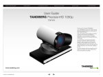
TANDBERG PrecisionHD 1080p/720p camera
Contents
Contents
Introduction
Introduction
Physical
Physical interface
interface
Cables
Cables
Camera User Guide
Connecti
Connect to
to codec
codec
Video
Video formats
formats
Daisy
Daisy chaining
chaining
Appendices
Appendices
Contact
Contact us
us
Software version TC3.0
MARCH 2010
PrecisionHD 1080p
12X/4X
PrecisionHD 720p
PrecisionHD Camera User Guide
D14640.01—MARCH 2010
1
www.tandberg.com
TANDBERG PrecisionHD 1080p/720p camera
Contents
Contents
Contents
Introduction
Introduction
Physical
Physical interface
interface
What’s in
this guide?
TA - ToC - Hidden
text anchor
The top menu bar and the entries in the Table
of Contents are all hyperlinks, just click on
them to go to the topic.
We recommend you visit the TANDBERG
web site regularly for updated versions of this
guide. Go to: http://www.tandberg.com/docs
Cables
Cables
Camera User Guide
Connecti
Connect to
to codec
codec
Video
Video formats
formats
Daisy
Daisy chaining
chaining
Appendices
Appendices
Contact
Contact us
us
Table of Contents
Connecting the camera to the codec
Introduction
Introduction............................................................................. 5
The purpose of this document............................................. 5
Products covered in this guide............................................ 5
Disclaimers and Notices...................................................... 5
Other documents you might find useful............................... 5
The physical interface
The PrecisionHD 1080p 12X/4X camera................................. 7
HDMI and HD-SDI*.............................................................. 7
Camera control.................................................................... 7
Power.................................................................................. 7
Extra camera*...................................................................... 7
Ethernet............................................................................... 7
Kensington lock................................................................... 7
The PrecisionHD 720p camera................................................ 8
HDMI................................................................................... 8
Camera control.................................................................... 8
Power.................................................................................. 8
Extra camera....................................................................... 8
Kensington lock................................................................... 8
About cables
Camera cables...................................................................... 10
HDMI cable........................................................................ 10
HD–SDI cable.................................................................... 10
HDMI to DVI–D adapter..................................................... 10
Making your own cables.................................................... 10
Codec C20 configurations..................................................... 12
Using the camera with Quick Set C20/C20plus................ 12
How to connect the camera.......................................... 12
Using the camera with Profile having Codec C20.............. 12
How to connect the camera.......................................... 12
Codec C40 configurations..................................................... 12
Using the camera with Codec C40.................................... 12
How to connect the camera.......................................... 12
Codec C60 configurations..................................................... 12
Using the camera with Codec C60.................................... 12
How to connect the camera.......................................... 12
Using the camera with Profile having Codec C60.............. 12
How to connect the camera.......................................... 12
Codec C90 configurations..................................................... 13
Using the camera with Codec C90.................................... 13
How to connect the camera.......................................... 13
Using the camera with Profile having Codec C90.............. 13
How to connect the camera.......................................... 13
Video output formats
TANDBERG PrecisionHD 1080p 12X/4X............................... 15
Video output formats......................................................... 15
DIP switch settings for video output formats..................... 15
Line voltage frequency....................................................... 15
The PrecisionHD 1080p video formats DIP switch table.... 15
Daisy chaining of the cameras
Daisy chaining of the PrecisionHD 1080p 12X/4X................. 17
Daisy chaining of the PrecisionHD 720p................................ 18
D14640.01—MARCH 2010
2
www.tandberg.com
TANDBERG PrecisionHD 1080p/720p camera
Contents
Contents
Contents
Introduction
Introduction
Physical
Physical interface
interface
Cables
Cables
Camera User Guide
Connecti
Connect to
to codec
codec
Video
Video formats
formats
Daisy
Daisy chaining
chaining
Appendices
Appendices
Contact
Contact us
us
Appendices
TANDBERG PrecisionHD 1080p 12X/4X camera.................. 20
Controlling cameras using the VISCA™ protocol............... 20
RS–232 Parameters.......................................................... 20
RS–232 Commands and inquiries..................................... 20
The VISCA™/RS–232 control protocol.................................. 21
VISCA message format...................................................... 21
Network and interface commands.................................... 22
Push messages................................................................. 22
Camera commands........................................................... 23
PTZF - movement commands........................................... 24
Inquiries............................................................................. 25
Software upload commands............................................. 26
Debug commands for TANDBERG cameras..................... 26
Other commands............................................................... 26
Video mode selection........................................................ 27
DIP Switch..................................................................... 27
Technical specifications......................................................... 28
TANDBERG PrecisionHD 1080p 12X/4X cameras............. 28
TANDBERG PrecisionHD 1080p 12X............................. 28
TANDBERG PrecisionHD 1080p 4X............................... 28
TANDBERG PrecisionHD 720p camera............................. 28
D14640.01—MARCH 2010
3
www.tandberg.com
TANDBERG PrecisionHD 1080p/720p camera
Contents
Contents
Introduction
Introduction
Introduction
Physical
Physical interface
interface
Camera User Guide
Cables
Cables
Connecti
Connect to
to codec
codec
Video
Video formats
formats
Daisy
Daisy chaining
chaining
Appendices
Appendices
Contact
Contact us
us
Chapter 1
Introduction
PrecisionHD 1080p
12X/4X
PrecisionHD 720p
www.tandberg.com
D14640.01—MARCH 2010
4
www.tandberg.com
TANDBERG PrecisionHD 1080p/720p camera
Contents
Contents
Introduction
Introduction
Introduction
Physical
Physical interface
interface
Introduction
You may already be familiar with the administrator guides
for the Profiles and Codec C–series. To help you find
the information you need, TANDBERG has split the
information into smaller and more accessible parts listed
on the right of this page.
Cables
Cables
Camera User Guide
Connecti
Connect to
to codec
codec
The purpose of this document
The purpose of this document is to describe the camera
matters specific to the PrecisionHD 1080p/720p
cameras, used together with the TANDBERG endpoints.
The guide is mainly focused on the PrecisionHD 1080p
12X/4X cameras, which are used together with the Profile
42”/52”/65”, the QuickSet C20/C20plus and the Codec
C–series. Some information about the PrecisionHD 720p
is also included.
Video
Video formats
formats
Daisy
Daisy chaining
chaining
Appendices
Appendices
Contact
Contact us
us
Products covered in this guide
• TANDBERG PrecisionHD cameras:
• TANDBERG PrecisionHD 1080p 12X/4X cameras
• TANDBERG PrecisionHD 720p camera
Other documents you might find useful
• Video conference room primer guide
• Getting started guide for Profile Series, Codec C Series, Quick Set C20
Disclaimers and Notices
The objective of this documentation is to provide the
reader with assistance in using and configuring the
product. The capabilities of TANDBERG products and
other manufacturers’ products change over time and
so the required configuration may be different from
that indicated here. If you have any suggestions for
changes to this document, please feed them back
to TANDBERG through your TANDBERG Authorized
Service Representative.
If you need technical support, please contact your
TANDBERG Authorized Service Representative.
The specifications for the product and the information
in this Guide are subject to change at any time, without
notice, by TANDBERG. Every effort has been made to
supply complete and accurate information in this Guide;
however, TANDBERG assumes no responsibility or
liability for any errors or inaccuracies that may appear in
this document.
• User Guide for Profile Series, Codec C Series and Quick Set C20
• Administrator guide for Profiles using Codec C20 and Quick Set C20
• Administrator guide for Profiles using Codec C60 and Codec C60
• Administrator guide for Profiles using Codec C90 and Codec C90
• Administrator guide for Codec C40
• Safety instructions for Profile Series, Codec C Series and Quick Set C20
• Legal information for Profile Series, Codec C Series and Quick Set C20
• Camera user guide for PrecisionHD 1080p/720p
• API guides for Codec C90, C60, C40
• Physical interfaces guides for Codec C90, C60, C40
Download the user documentation
Go to:
http://www.tandberg.com/docs
TANDBERG® is a registered trademark belonging to
Tandberg ASA. Other trademarks used in this document
are the property of their respective holders.
This Guide may be reproduced in its entirety, including
all copyright and intellectual property notices, in limited
quantities in connection with the use of this product.
Except for the limited exception set forth in the previous
sentence, no part of this Guide may be reproduced,
stored in a retrieval system, or transmitted, in any
form, or by any means, electronically, mechanically, by
photocopying, or otherwise, without the prior written
permission of TANDBERG.
www.tandberg.com
© 2010 TANDBERG
D14640.01—MARCH 2010
5
www.tandberg.com
TANDBERG PrecisionHD 1080p/720p camera
Contents
Contents
Introduction
Introduction
Physical
interface
Physical
interface
Interface
Camera User Guide
Cables
Cables
Connecti
Connect to
to codec
codec
Video
Video formats
formats
Daisy
Daisy chaining
chaining
Appendices
Appendices
Contact
Contact us
us
Chapter 2
The physical interface
PrecisionHD 1080p
12X/4X
PrecisionHD 720p
www.tandberg.com
D14640.01—MARCH 2010
6
www.tandberg.com
TANDBERG PrecisionHD 1080p/720p camera
Contents
Contents
Introduction
Introduction
Physical
interface
Physical
interface
Interface
Cables
Cables
Camera User Guide
Connecti
Connect to
to codec
codec
Video
Video formats
formats
Daisy
Daisy chaining
chaining
Appendices
Appendices
Contact
Contact us
us
The PrecisionHD 1080p 12X/4X camera
The orange LED illuminates while in
a call and flickers when there is an
incoming call.
The lens hood is
detachable.
We recommend that you
mount it to prevent stray
light from disturbing your
video experience.
Snap it on gently.
Kensington lock
Power
Supply
HDMI
Video Out
Camera
Control
Extra Camera
Out and for Daisy
Chaining*
The green LED is continuously
illuminated when power is On, but
it flickers when receiving signals
from the remote control.
When mounted (upside down) in
the Profile 65” and the Profile 65”
Dual, the LED is not visible.
HD-SDI Out*
HDMI and HD-SDI*
Extra camera*
• HDMI is the main video source. The maximum resolution is
1080p60.
If you want to connect cameras in a daisy chain:
• HD-SDI is the secondary video source. The maximum
resolution is 1080p30.
• The HDMI and HD-SDI can be used simultaneously. The
maximum resolution is 1080p30, if you want both to run with
the same resolution.
• The first camera in the chain is powered by the camera
control cable. The next must use the 12V DC Power in.
• Use an extra camera cable between the Extra Camera
sockets.
Ethernet
Camera control is used for controlling the pan, tilt and zoom,
and for powering up the camera.
For software upgrades on daisy chained cameras. Requires
software version TC3.0 or higher on the Codec C–series. See
the TANDBERG PrecisionHD 12x Ethernet Upgrade Application
Note for details. Go to: http://www.tandberg.com/docs
Power
Kensington lock
• When the camera is used with a TANDBERG Codec, power
will be supplied through Camera Control cable.
The Kensington lock may be used to prevent the camera to be
moved from its place or to prevent theft.
Camera control
• When the camera is used with non-TANDBERG codecs, you
may have to connect power separately.
D14640.01—MARCH 2010
Ethernet
RJ45
7
* Not supported with Codec C20
www.tandberg.com
TANDBERG PrecisionHD 1080p/720p camera
Contents
Contents
Introduction
Introduction
Physical
interface
Physical
interface
Interface
Cables
Cables
Camera User Guide
Connecti
Connect to
to codec
codec
Video
Video formats
formats
Daisy
Daisy chaining
chaining
Appendices
Appendices
Contact
Contact us
us
The PrecisionHD 720p camera
The orange LED illuminates while in
a call and flickers when there is an
incoming call.
The lens hood (not
mounted on the camera in
the picture) is detachable.
We recommend that you
mount it to prevent stray
light from disturbing your
video experience.
Snap it on gently.
VISCA
Daisy
chain
The green LED is continuously
illuminated when power is On, but
it flickers when receiving signals
from the remote control.
Power in
12 V DC
HDMI
video
out
Camera
control &
Power
Kensington
lock
HDMI
Extra camera
• HDMI is the main video source. The maximum resolution is
720p30.
If you want to connect cameras in a daisy chain*:
Camera control
Camera control is used for controlling the pan, tilt and zoom,
and for powering up the camera.
Power
• When the camera is used with a TANDBERG Codec, power
will be supplied through Camera Control cable.
• The first camera in the chain is powered by the camera
control cable. The next must use the 12V DC Power in.
• Use an extra camera cable between the Extra Camera
sockets.
Kensington lock
The Kensington lock may be used to prevent the camera to be
moved from its place or to prevent theft.
• When the camera is used with non-TANDBERG codecs, you
may have to connect power separately.
* Not supported with Codec C20
D14640.01—MARCH 2010
8
www.tandberg.com
TANDBERG PrecisionHD 1080p/720p camera
Contents
Contents
Introduction
Introduction
Physical
Physical interface
interface
Camera User Guide
Cables
Cables
Cables
Connecti
Connect to
to codec
codec
Video
Video formats
formats
Daisy
Daisy chaining
chaining
Appendices
Appendices
Contact
Contact us
us
Chapter 3
About cables
PrecisionHD 1080p
12X/4X
PrecisionHD 720p
www.tandberg.com
D14640.01—MARCH 2010
9
www.tandberg.com
TANDBERG PrecisionHD 1080p/720p camera
Contents
Contents
Introduction
Introduction
Physical
Physical interface
interface
Camera cables
Cables
Cables
Cables
Camera User Guide
Connecti
Connect to
to codec
codec
Video
Video formats
formats
Daisy
Daisy chaining
chaining
Appendices
Appendices
Contact
Contact us
us
Making your own cables
If you must assemble your own cables, the tables show the pin-out required.
HDMI cable
The HDMI cable delivered with the camera is 5 meters.
Pin-out—VISCA Camera control
Maximum length is 15 meter with a category 2 certified good
quality HDMI cable.
Pin-out—VISCA Daisy chain
RJ 45 8 pins shielded modular jack
RJ 11 6 pins modular jack
Pin
Signal name
Pin
Signal name
8
+12V (2.8mA current source when
connected in daisy chain)
6
GND
5
GND
7
GND
4
RXD (in)
6
TXD (out)
3
TXD (out)
5
NC (no connect)
HDMI to DVI–D adapter
2
Presence (12V in daisy chain)
4
NC (no connect)
The HDMI to DVI–D adapter is used when connecting to a
TANDBERG MXP Codec or TANDBERG Video Switch.
1
GND
3
RXD (in)
2
GND
1
+12V
HD–SDI cable
The HD-SDI cable must be purchased separately. The maximum
recommended length of HD–SDI cable is 100 meters.
Pin-out—TANDBERG camera cable
RJ45 (8 pin) to D-SUB
D14640.01—MARCH 2010
Signal
name
RJ45 pin
D-SUB pin
+12Vdc
1
4
GND
2
Twisted
pair
RX
3
2
TX
6
Twisted
pair
NC
4
1
NC
5
Twisted
pair
GND
7
5
+12Vdc
8
Twisted
pair
10
5
3
6
4
www.tandberg.com
TANDBERG PrecisionHD 1080p/720p camera
Contents
Contents
Introduction
Introduction
Physical
Physical interface
interface
Camera User Guide
Connecti
to
Connect
to codec
codec
Connecting
Cables
Cables
Video
Video formats
formats
Daisy
Daisy chaining
chaining
Appendices
Appendices
Contact
Contact us
us
Chapter 4
Connecting the camera to the codec
PrecisionHD 1080p
12X/4X
PrecisionHD 720p
www.tandberg.com
D14640.01—MARCH 2010
11
www.tandberg.com
TANDBERG PrecisionHD 1080p/720p camera
Contents
Contents
Introduction
Introduction
Physical
Physical interface
interface
Codec C20 configurations
Camera
control
Camera
HDMI
Cables
Cables
Camera User Guide
Connecti
to
Connect
to codec
codec
Connecting
Video
Video formats
formats
Codec C40 configurations
HDMI 1
Daisy
Daisy chaining
chaining
Appendices
Appendices
Contact
Contact us
us
Codec C60 configurations
Camera
control
HDMI 1
Camera
control
Using the camera with Quick Set C20/C20plus
Using the camera with Codec C40
Using the camera with Codec C60
• The TANDBERG Quick Set C20, using the Codec C20,
includes the PrecisionHD 1080p 4X zoom with 1080p30
maximum resolution.
• The TANDBERG Codec C60 includes the PrecisionHD 1080p
12X zoom with 1080p60 maximum resolution.
• The TANDBERG Codec C60 includes the PrecisionHD 1080p
12X zoom with 1080p60 maximum resolution.
• The Codec C60 can also be used with PrecisionHD 720p with
1280x720p30 maximum resolution.
• The Codec C60 can also be used with PrecisionHD 720p with
1280x720p30 maximum resolution.
How to connect the camera
How to connect the camera
Connect the HDMI cable (HDMI to HDMI):
Connect the HDMI cable (HDMI to HDMI):
• From the HD VIDEO OUT (HDMI) connector on the camera.
• From the HD VIDEO OUT (HDMI) connector on the camera.
• To the HDMI 1 IN (HDMI) connector on the Codec C40.
• To the HDMI 1 IN (HDMI) connector on the Codec C60.
Connect the camera control cable (RJ45 to RS–232):
Connect the camera control cable (RJ45 to RS–232):
Connect the camera control cable (RJ45 to RS–232):
• From the CODEC CONTROL IN (RJ45) connector on the
camera.
• From the CODEC CONTROL IN (RJ45) connector on the
camera.
• From the CODEC CONTROL IN (RJ45) connector on the
camera.
• To the CAMERA CONTROL (RS–232) connector on the
Codec C40.
• To the CAMERA CONTROL (RS–232) connector on the
Codec C60. Visca™ protocol is supported.
• The TANDBERG Quick Set C20plus, using the Codec C20,
includes the PrecisionHD 1080p 12X zoom with 1080p60
maximum resolution.
How to connect the camera
Connect the HDMI cable (HDMI to HDMI):
• From the HD VIDEO OUT (HDMI) connector on the camera.
• To the CAMERA (HDMI) connector on the Codec C20.
• To the CAMERA CONTROL (RS–232) connector on the
Codec C20. Visca™ protocol is supported.
Using the camera with Profile having Codec C60
The TANDBERG Profile 42”/52”/65” with Codec C60 includes the
PrecisionHD 1080p 12X zoom with 1080p60 maximum resolution.
Using the camera with Profile having Codec C20
The TANDBERG Profile 42”, using the Codec C20, includes the
PrecisionHD 1080p 12X zoom with 1080p60 maximum resolution.
How to connect the camera
The camera cables are pre-mounted on the Profile room systems.
How to connect the camera
The camera cables are pre-mounted on the Profile room systems.
D14640.01—MARCH 2010
12
www.tandberg.com
TANDBERG PrecisionHD 1080p/720p camera
Contents
Contents
Introduction
Introduction
Physical
Physical interface
interface
Cables
Cables
Camera User Guide
Connecti
to
Connect
to codec
codec
Connecting
Video
Video formats
formats
Daisy
Daisy chaining
chaining
Appendices
Appendices
Contact
Contact us
us
Codec C90 configurations
HDMI 1
Camera
control
Using the camera with Codec C90
• The TANDBERG Codec C90 includes the PrecisionHD 1080p
12X zoom with 1080p60 maximum resolution.
• The Codec C90 can also be used with PrecisionHD 720p with
1280x720p30 maximum resolution.
How to connect the camera
Connect the HDMI cable (HDMI to HDMI):
• From the HD VIDEO OUT (HDMI) connector on the camera.
• To the HDMI 1 IN (HDMI) connector on the Codec C90.
Connect the camera control cable (RJ45 to RS–232):
• From the CODEC CONTROL IN (RJ45) connector on the
camera.
• To the CAMERA CONTROL (RS–232) connector on the
Codec C90. Visca™ protocol is supported.
Using the camera with Profile having Codec C90
The TANDBERG Profile 65” with Codec C90 includes the
PrecisionHD 1080p 12X zoom with 1080p60 maximum resolution.
How to connect the camera
The camera cables are pre-mounted on the Profile room systems.
D14640.01—MARCH 2010
13
www.tandberg.com
TANDBERG PrecisionHD 1080p/720p camera
Contents
Contents
Introduction
Introduction
Physical
Physical interface
interface
Cables
Cables
Camera User Guide
Connecti
Connect to
to codec
codec
Video
Video formats
formats
Video
formats
Daisy
Daisy chaining
chaining
Appendices
Appendices
Contact
Contact us
us
Chapter 5
Video output formats
PrecisionHD 1080p
12X/4X
www.tandberg.com
D14640.01—MARCH 2010
14
www.tandberg.com
TANDBERG PrecisionHD 1080p/720p camera
Contents
Contents
Introduction
Introduction
Physical
Physical interface
interface
TANDBERG PrecisionHD 1080p
12X/4X
Cables
Cables
Camera User Guide
Connecti
Connect to
to codec
codec
Video
Video formats
formats
Video
formats
Daisy
Daisy chaining
chaining
Appendices
Appendices
Contact
Contact us
us
The PrecisionHD 1080p video formats DIP switch table
Video output formats
NOTE: The information on this page applies to the PrecisionHD
1080p 12X/4X camera, and describes how to set the DIP switches
1–5 to configure the camera for different video output formats.
DIP Switch table for video formats
1
0
1
2
3
4
5
HDMI
HD-SDI*
0
0
0
0
0
0
0
0
0
1
1920x1080p25
1920x1080p25
0
0
0
1
0
1920x1080p30
1920x1080p30
0
0
0
1
1
1920x1080p50
1280x720p50
0
0
1
0
0
1920x1080p60
1280x720p60
• 1080p30 for PrecisionHD 1080p 4X zoom
0
0
1
0
1
1280x720p25
1280x720p25
• Maximum resolution for HD-SDI* is 1080p30.
0
0
1
1
0
1280x720p30
1280x720p30
0
0
1
1
1
1280x720p50
1280x720p50
0
1
0
0
0
1280x720p60
1280x720p60
0
1
0
0
1
DIP switch settings for video output formats
The DIP switch
The DIP switch sets the video output format for the camera. The
DIP switch is on the underside of the camera. The default setting
is Auto. See the table to the right.
• Maximum resolution for HDMI is:
• 1080p60 for PrecisionHD 1080p 12X zoom
Line voltage frequency
The camera will automatically detect the line voltage frequency
when it is 50 or 60 Hz. If there is a different line voltage, you
can set the video output format to a specific value (use the DIP
switches) to override the auto frequency detection.
Set the PrecisionHD 1080p DIP switch (country specific setting):
• 50Hz: 00011, gives 1080p50 (720p50 for HD-SDI)
• 60Hz: 00100, gives 1080p60 (720p60 for HD-SDI)
Underside side of the
TANDBERG PrecisionHD
1080p camera
Auto
Software control
The table shows the different settings available for the HDMI
and the HD-SDI outputs.
Auto: Camera negotiates format over HDMI. HD-SDI tracks
HDMI and defaults to 1080p30 in absence of HDMI sync.
Software: For more on the Software control setting, read about
video mode selections in the TANDBERG PrecisionHD 1080p
User Guide.
* Not supported with Codec C20
D14640.01—MARCH 2010
15
www.tandberg.com
TANDBERG PrecisionHD 1080p/720p camera
Contents
Contents
Introduction
Introduction
Physical
Physical interface
interface
Cables
Cables
Camera User Guide
Connecti
Connect to
to codec
codec
Video
Video formats
formats
Daisy
Daisy chaining
chaining
Daisy
chaining
Appendices
Appendices
Contact
Contact us
us
Chapter 6
Daisy chaining of the cameras
PrecisionHD 1080p
12X/4X
PrecisionHD 720p
www.tandberg.com
D14640.01—MARCH 2010
16
www.tandberg.com
TANDBERG PrecisionHD 1080p/720p camera
Contents
Contents
Introduction
Introduction
Daisy chaining of the
PrecisionHD 1080p
12X/4X
A single daisy chain with PrecisionHD 1080p
12X can have:
• Three cameras when using Codec C60.
Physical
Physical interface
interface
Cables
Cables
Camera User Guide
Connecti
Connect to
to codec
codec
Video
Video formats
formats
Daisy
Daisy chaining
chaining
Daisy
chaining
Appendices
Appendices
Contact
Contact us
us
Example. TANDBERG PrecisionHD 1080p 12X/4X cameras in daisy chain.
Power in
Power in
12V DC
12V DC
Main
camera
Second
camera
Third
camera
• Seven cameras when using Codec C90.
The PrecisionHD 1080p 4X has daisy chain
support, but can only be in the end of a chain.
Locate the Extra Camera and Power
connectors.
RJ11–RJ45
RJ11–RJ45
• Power. The first camera in the chain is
powered up from the codec by the VISCA
camera control cable. Additional cameras
must use the 12V DC Power in.
• Extra camera cable. The daisy chained
cameras are connected by using the VISCA
Extra Camera cable (maximum length 20 m
/ 65.6 ft) between the Extra Camera In and
Codec Control In sockets.
Connect to the
Camera Control
socket on the
codec.
HDMI out:
Connect to the
Video Input 1
on the codec
• HDMI and HD-SDI. The HDMI and HD-SDI
outputs can be used simultaneously on the
same camera.
D14640.01—MARCH 2010
RJ11–RJ45
HDMI out:
HDMI out:
Connect to the
Video Input 2
on the codec
Connect to the
Video Input 3
on the codec
You can connect
up to three
cameras with
Codec C60 and up
to seven cameras
with Codec C90
VISCA™ is a trademark of Sony Corporation
17
www.tandberg.com
TANDBERG PrecisionHD 1080p/720p camera
Contents
Contents
Introduction
Introduction
Daisy chaining of the
PrecisionHD 720p
Physical
Physical interface
interface
Cables
Cables
Camera User Guide
Connecti
Connect to
to codec
codec
Video
Video formats
formats
Daisy
Daisy chaining
chaining
Daisy
chaining
Appendices
Appendices
Contact
Contact us
us
Example. TANDBERG PrecisionHD 720p cameras in daisy chain.
A single daisy chain can have:
Power in
Power in
• Three cameras when using Codec C60
12V DC
12V DC
• Seven cameras when using Codec C90.
Main
camera
Locate the Extra Camera and Power
connectors.
Second
camera
Third
camera
• Power. The first camera in the chain is
powered up from the codec by the VISCA
camera control cable. Additional cameras
must use the 12V DC Power in.
• Extra camera cable. The daisy chained
cameras are connected by using the VISCA
Extra Camera cable (maximum length 20 m
/ 65.6 ft) between the Extra Camera and
Codec Control sockets
RJ11–RJ45
You can connect
up to three
cameras with
Codec C60 and up
to seven cameras
with Codec C90
RJ11–RJ45
RJ11–RJ45
HDMI out:
Connect to the
Video Input 1
on the codec
Connect to the
Camera Control
socket on the
codec.
HDMI out:
HDMI out:
Connect to the
Video Input 2
on the codec
Connect to the
Video Input 3
on the codec
VISCA™ is a trademark of Sony Corporation
D14640.01—MARCH 2010
18
www.tandberg.com
TANDBERG PrecisionHD 1080p/720p camera
Contents
Contents
Introduction
Introduction
Physical
Physical interface
interface
Camera User Guide
Cables
Cables
Connecti
Connect to
to codec
codec
Video
Video formats
formats
Daisy
Daisy chaining
chaining
Appendices
Appendices
Appendices
Contact
Contact us
us
Chapter 7
Appendices
PrecisionHD 1080p
12X/4X
PrecisionHD 720p
www.tandberg.com
D14640.01—MARCH 2010
19
www.tandberg.com
TANDBERG PrecisionHD 1080p/720p camera
Contents
Contents
Introduction
Introduction
Physical
Physical interface
interface
TANDBERG PrecisionHD 1080p
12X/4X camera
Cables
Cables
Camera User Guide
Connecti
Connect to
to codec
codec
Video
Video formats
formats
Daisy
Daisy chaining
chaining
Appendices
Appendices
Appendices
Contact
Contact us
us
RS–232 Parameters
At startup, the communication parameters for the RS–232 interface must be set to:
• 9600 bits per second
• 8 data bits
Controlling cameras using the VISCA™ protocol
• No parity
• 1 stop bit
NOTE: The information in this chapter applies to the TANDBERG
PrecisionHD 1080p 12X/4X camera.
• No hardware flow control
The camera uses an RS-232 control interface that resembles
the Sony VISCA™ protocol. The VISCA protocol (VIdeo System
Control Architecture) is a Sony protocol for synchronized control
of multiple video peripherals.
All the RS–232 parameters except speed are fixed and not user configurable. The speed may be
changed by issuing the Speed command defined on the following pages.
• No software flow control
All control bytes are pure binary information, i.e. the control bytes are not ASCII-encoded.
VISCA™ is a trademark of Sony Corporation
RS–232 Commands and inquiries
A list of all the available commands and inquiries together with the result and comments are found in
the table on the following pages.
D14640.01—MARCH 2010
20
www.tandberg.com
TANDBERG PrecisionHD 1080p/720p camera
Contents
Contents
Introduction
Introduction
The VISCA™/RS–232
control protocol
Physical
Physical interface
interface
Cables
Cables
Camera User Guide
Connecti
Connect to
to codec
codec
Video
Video formats
formats
Daisy
Daisy chaining
chaining
When the camera receives a command, it
responds with either:
• Completion message: 90-5Y-FF
Returned by camera when execution of
commands and inquiries are completed.
Packet (3 to 16 bytes)
Address
Message (1 to 14 bytes)
Byte 1
Byte 2
...
Byte 3
Terminator
• Error packets: 90-6Y-..-FF
Returned by camera instead of a completion
message when command or inquiry failed to
be executed.
FF
General error messages, unless otherwise
specified:
VISCA message format
A particular command is recognized by the
message information after the address byte.
Message Format
1
Sender’s
address
0
1 1 1 1 1 1 1 1
LSB
LSB
Receiver’s
address
• Address byte (1)
• Message bytes (1..14)
• Terminator byte (1)
See the illustration for details.
• 90-6Y-01-FF Message length error
(>14 bytes)
• 90-6Y-02-FF Syntax error
• 90-6Y-03-FF Command buffer full
• 90-6Y-04-FF Command cancelled
Commands are initiated from the host (i.e. the
codec or any other external controller) to the
camera.
After a camera has been issued a command,
the camera will generate a response.
Commands and responses (messages) have the
following format:
Contact
Contact us
us
Command and response exchange
The RS232 Message format
When interfacing to the PrecisionHD 12X/4X
1080p, the codec uses an RS-232 control
interface that resembles the Sony VISCA™
protocol.
Appendices
Appendices
Appendices
• 90-6Y-05-FF No socket (to be cancelled)
• 90-6Y-41-FF Command not executable
The minimum length of any command or response is 3 bytes:
1. Address byte (1): Let us assume there is one host, i.e. the codec (the host is the unit controlling
the camera). The host has address 0. The four least significant bits of the address byte contain the
address of the receiver. In the case of a broadcast message, the receiver address must be set to
8. When we are operating a single camera, the address is 1. Hence, address bytes in messages
from the host are 0x81, and messages from the camera to the host are 0x90 (the protocol allows
for up to 7 cameras).
2. Message bytes (1..14): Any number of bytes containing the actual message information. Bytes
may have any value in the range 0...254. The value 255 (i.e. hexadecimal FF) is reserved for the
terminating byte.
3. Terminator byte (1): All messages must be terminated with a byte containing all 1’s, i.e. decimal
255 (or hexadecimal FF).
• Y = socket number
A camera may contain two buffers so that
two commands, including the command
being executed, can be received.
NOTE: The PrecisionHD 1080p camera
supports a single socket only. Consequently,
the Y always assumes the value Y = 0.
Exceptions to these rules:
• An Initialize message will respond as
indicated in the Table of Commands (this
message is in fact a broadcast message,
and any unit other than the host receiving the
broadcast message must pass it on).
• Do not route commands or replies that are
longer than 16 bytes through Sony cameras.
The easiest way to avoid this is to put the
TANDBERG cameras first in the chain.
Commands and replies that are longer than
16 bytes are clearly marked below.
D14640.01—MARCH 2010
21
www.tandberg.com
TANDBERG PrecisionHD 1080p/720p camera
Contents
Contents
Introduction
Introduction
Physical
Physical interface
interface
Cables
Cables
Camera User Guide
Connecti
Connect to
to codec
codec
Video
Video formats
formats
Daisy
Daisy chaining
chaining
Appendices
Appendices
Appendices
Contact
Contact us
us
The VISCA™/RS–232 control protocol, cont...
Push messages
Network and interface commands
Command set
Command packet
Messages sent from camera to controller.
Comments
IF_Clear
8x 01 00 01 ff
Clear command buffer. Stop any
current operation in progress. Does not
do much on Rover.
Address_Set
8x 30 0p ff
p = address for this device. If x=8
(broadcast), increase p with 1 before
sending to chain.
Command_
Cancel
8x 2p ff
p = Socket ID. Rover does not support
multiple sockets. Commands will
always run to completion. Don’t use it
D14640.01—MARCH 2010
Command set
Network_
Change
Command packet
y0 38 ff
Reply and comments
This indicates that cameras have been added
to or removed from the chain.
It is recommended to wait 9 seconds after
receiving this message before doing a full
reconfigure.
IR_Push
22
y0 07 7d 02 gg hh ff
If IR mode is on, IR codes received by the
camera will be sent to the controller.
gg = IR ID
hh = keycode
www.tandberg.com
TANDBERG PrecisionHD 1080p/720p camera
Contents
Contents
Introduction
Introduction
Physical
Physical interface
interface
Cables
Cables
Camera User Guide
Connecti
Connect to
to codec
codec
Video
Video formats
formats
Daisy
Daisy chaining
chaining
Appendices
Appendices
Appendices
Contact
Contact us
us
The VISCA™/RS–232 control protocol, cont...
Camera commands
Command
Command Packet
Power_On
8x 01 04 00 02 ff
Power_Off
8x 01 04 00 03 ff
Video_Format
8x 01 35 0p 0q 0r ff
Comments
Power control. This command
stores the zoom and focus value
and reset these motors. Used for
Tiger if the camera was on for a
long time.
Command Packet
Comments
MM_Detect_On
8x 01 50 30 01 ff
Turn on the Motor Moved
Detection (camera recalibrates if
touched)
MM_Detect_Off
8x 01 50 30 00 ff
Selects video format. p =
reserved. q = video mode. r =
See the chapter about the DIP
switch settings
Turn off the Motor Moved
Detection (camera does not
recalibrate if touched)
Call_LED_On
8x 01 33 01 01 ff
Call_LED_Off
8x 01 33 01 00 ff
WB: White Balance
Call_LED_Blink
8x 01 33 01 02 ff
Refers to orange LED on top
of camera. Will always be off at
startup.
Power_LED_On
8x 01 33 02 01 ff
Power_LED_Off
8x 01 33 02 00 ff
WB_Auto
8x 01 04 35 00 FF
WB_Table_Manual
8x 01 04 35 06 ff
WB_Table_Direct
8x 01 04 75 0p 0q 0r 0s ff
Used if WBmode = Table manual
pqrs = wb table.
AE_Auto
8x 01 04 39 00 FF
AE: Automatic Exposure.
AE_Manual
8x 01 04 39 03 FF
Iris_Direct
8x 01 04 4B 0p 0q 0r 0s FF
Used if AE mode = Manual. pqrs:
Iris position, range 0..50
Gain_Direct
8x 01 04 4c 0p 0q 0r 0s FF
Used if AE mode = Manual. pqrs:
Gain position, values:12-21dB.
Backlight_On
8x 01 04 33 02 FF
BacklightCompensation mode
Backlight_Off
8x 01 04 33 03 FF
Mirror_On
8x 01 04 61 02 ff
Mirror_Off
8x 01 04 61 03 ff
Flip_On
8x 01 04 66 02 ff
Flip_Off
8x 01 04 66 03 ff
Gamma_Auto
8x 01 04 51 02 ff
Gamma_Manual
8x 01 04 51 03 ff
Gamma_Direct
8x 01 04 52 0p 0q 0r 0s ff
D14640.01—MARCH 2010
Command
IR_Output_On
8x 01 06 08 02 ff
IR_Output_Off
8x 01 06 08 03 ff
IR_CameraControl_On
8x 01 06 09 02 ff
IR_CameraControl_Off
8x 01 06 09 03 ff
Green power LED. If switched to
off and stored to startup profile, it
will always be off.
See IR push message.
Lets up/down/left/right/zoom+/on the IR remote control the
camera directly. Those keycodes
will be sent to the controller if IR
Output is on.
Sony calls this CAM_LR_Reverse.
RR (FT/AT mirror command)
Sony calls this CAM_ImgFlip.
Gamma mode. Default uses
gamma table 4.
pqrs: Gamma table to use in
manual mode. Range 0-7.
23
www.tandberg.com
TANDBERG PrecisionHD 1080p/720p camera
Contents
Contents
Introduction
Introduction
Physical
Physical interface
interface
Cables
Cables
Camera User Guide
Connecti
Connect to
to codec
codec
Video
Video formats
formats
Daisy
Daisy chaining
chaining
Appendices
Appendices
Appendices
Contact
Contact us
us
The VISCA™/RS–232 control protocol, cont...
PTZF - movement commands
Command
Command Packet
Comments
Zoom_Stop
8x 01 04 07 00 ff
Zoom_Tele
8x 01 04 07 2p ff
Zoom_Wide
8x 01 04 07 3p ff
Zoom_Direct
8x 01 04 47 0p 0q 0r 0s ff
pqrs: zoom position
ZoomFocus_Direct
8x 01 04 47 0p 0q 0r
pqrs: zoom position
0s
tuvw: focus position
Command
PT_Direct
p = speed parameter,
a (low) to b (high)
8x 01 06 02 0p 0t 0q 0r 0s
0u 0v 0w 0x 0y FF
Comments
p: max pan speed
t: max tilt speed
qrsu: pan position
vwxy: tilt position
Attempts to linearize movement.
PTZF_Direct
0t 0u 0v 0w ff
8x 01 06 20 0p 0q 0r 0s 0t
0u 0v 0w 0x 0y 0z 0g 0h
0i 0j 0k ff
NOTE: Never route this message
through Sony cameras.
Sets all motors in one operation.
p = speed parameter,
a (low) to b (high)
pqrs: pan
tuvw: tilt
xyzg: zoom
hijk: focus
8x 01 04 48 0p 0q 0r 0s ff
pqrs: focus position
Attempts to linearize movement for pan
and tilt.
8x 01 04 38 02 ff
Autofocus mode on/off.
Focus_Stop
8x 01 04 08 00 ff
Focus_Far
8x 01 04 08 2p ff
Focus_Near
8x 01 04 08 3p ff
Focus_Direct
Focus_Auto
PT_Limit_Set
NOTE: If mode is auto, camera may
disable autofocus when focus is ok.
Autofocus will be turned back on when
camera is moved using Zoom_Tele/
Wide, PT_Up/Down/Left/Right. Ditto
for IR_CameraControl movement.
Focus_Manual
8x 01 04 38 03 ff
PT_Stop
8x 01 06 01 03 03 03 03 ff
PT_Reset
8x 01 06 05 ff
Reset pan/tilt to center position. Will
also re–synchronize motors.
PT_Up
8x 01 06 01 0p 0t 03 01 ff
PT_Down
8x 01 06 01 0p 0t 03 02 ff
p pan speed
t: tilt speed
PT_Left
8x 01 06 01 0p 0t 01 03 ff
PT_Right
8x 01 06 01 0p 0t 02 03 ff
PT_UpLeft
8x 01 06 01 0p 0t 01 01 ff
PT_UpRight
8x 01 06 01 0p 0t 02 01 ff
PT_DownLeft
8x 01 06 01 0p 0t 01 02 ff
PT_DownRight
8x 01 06 01 0p 0t 02 02 ff
D14640.01—MARCH 2010
Command Packet
8x 01 06 07 00 0x 0p 0q
0r 0s 0t 0u 0v 0w ff
x=1: Up/Right
x=0: Down/Left
pqrs: Pan limit
tuvx: Tilt limit.
This command is valid only to next
boot.
PT_Limit_Clear
8x 01 06 07 01 0x [...] ff
x=1: Up/Right
x=0: Down/Left
Sony specifies lots of filler bytes after
0x. Ignore them.
Right -> increment pan
Left -> decrement pan
Up -> increment tilt
Down -> decrement tilt
24
www.tandberg.com
TANDBERG PrecisionHD 1080p/720p camera
Contents
Contents
Introduction
Introduction
Physical
Physical interface
interface
Cables
Cables
Camera User Guide
Connecti
Connect to
to codec
codec
Video
Video formats
formats
Daisy
Daisy chaining
chaining
Appendices
Appendices
Appendices
Contact
Contact us
us
The VISCA™/RS–232 control protocol, cont...
Inquiries
Command
Command
Packet
Response
Command
Gamma_Mode_Inq
8x 09 04 51 ff
Resp: y0 50 0p ff
p=2: Auto, p=3: Manual
Gamma_Table_Inq
8x 09 04 52 ff
Resp: y0 50 0p 0q 0r 0s ff
pqrs: Gamma table in use if manual mode.
Call_LED_Inq
8x 09 01 33 01 ff
Resp: y0 50 0p ff
p=2: On, p=3: Off, p=4: Blink
Power_LED_Inq
8x 09 01 33 02 ff
Resp: y0 50 0p ff
p=2: On, p=3: Off
Video_System_Inq
8x 09 06 23 ff
y0 50 0p 0q 0r 0s ff
pqrs=video mode currently being output on the
HDMI port. See chapter on DIP switches.
DIP_Switch_Inq
8x 09 06 24 ff
y0 50 0p 0q 0r 0s ff pqrs contains the bit
pattern of the DIP switch. See chapter on DIP
switches.
IR_Output_Inq
8x 09 06 08 ff
Resp: y0 50 0p ff
p=2: On, p=3: Off
ALS_RGain_Inq
8x 09 50 50 ff
Ambient Light Sensor Resp: y0 50 0p 0q 0r 0s
0t 0u 0v 0w ff
CAM_ID_Inq
8x 09 04 22 ff
Resp: 90 50 zz xx 00 yy ff
Only zz, which identifies the camera, is relevant.
zz = 0x50 for this camera.
CAM_SWID_Inq
8x 09 04 23 ff
Resp: y0 50 [1-125 bytes ASCII SWID] ff. Never
route this message through Sony cameras.
CAM_HWID_Inq
8x 09 04 24 ff
The response is the Module Serial Number
stored in EEPROM. The number is converted to
ASCII : y0 50 [12 bytes ASCII HWID] ff.
Command
Packet
Zoom_Pos_Inq
8x 09 04 47 ff
Resp: y0 50 0p 0q 0r 0s ff
pqrs: zoom position
Focus_Pos_Inq
8x 09 04 48 ff
Resp: y0 50 0p 0q 0r 0s ff
pqrs: focus position
Focus_Mode_Inq
8x 09 04 38 ff
Resp: y0 50 0p ff
p=2: Auto, p=3: Manual
PanTilt_Pos_Inq
8x 09 06 12 ff
Resp: y0 50 0p 0q 0r 0s 0t 0u 0v 0w ff
pqrs: pan position tuvw:
tilt position
Power_Inq
8x 09 04 00 ff
Resp: y0 50 0p ff
p=2: On, p=3: Off
WB_Mode_Inq
8x 09 04 35 ff
Resp: y0 50 0p ff
p=0: Auto , p=6: Table manual
WB_Table_Inq
8x 09 04 75 ff
Resp: y0 50 0p 0q 0r 0s ff
pqrs: Table used if table mode
ALS_BGain_Inq
8x 09 50 51 ff
ALS_GGain_Inq
8x 09 50 52 ff
ALS_WGain_Inq
8x 09 50 53 ff
Up side down_Inq
8x 09 50 70 ff
AE_Mode_Inq
8x 09 04 39 ff
Resp: y0 50 0p ff
p=0: Auto, p=3: Manual
Backlight_Mode_
Inq
8x 09 04 33 ff
Resp: y0 50 0p ff
p=2: On, p=3: Off
Mirror_Inq
8x 09 04 61 ff
Resp: y0 50 0p ff
p=2: On, p=3: Off
Flip_Inq
8x 09 04 66 ff
Is video flipped or not?
Resp: y0 50 0p ff
p=2: On , p=3: Off
D14640.01—MARCH 2010
Response
pqrstuv=32 bit unsigned integer, relative gain
value. The integration time is a constant set in
the camera SW.
25
Resp: y0 50 0p ff
p=0: Camera is upright.
p=1: Camera is upside down.
www.tandberg.com
TANDBERG PrecisionHD 1080p/720p camera
Contents
Contents
Introduction
Introduction
Physical
Physical interface
interface
Cables
Cables
Camera User Guide
Connecti
Connect to
to codec
codec
Video
Video formats
formats
Appendices
Appendices
Appendices
Daisy
Daisy chaining
chaining
Contact
Contact us
us
The VISCA™/RS–232 control protocol, cont...
Software upload commands
Debug commands for TANDBERG cameras
The CRC algorithm used, is the same as in the XModem protocol. CRC for the last data packet is only
calculated for the actual data bytes in the packet. Pad last packet with 0x00 so that the data section
is 256 bytes long. The PacketID counter starts at 0.
NOTE: Never route these messages through Sony cameras. They are provided for debugging on the
TANDBERG PrecisionHD cameras only, and do not conform to the Visca length requirements.
Command set
SW start
SW end
Command packet
Comments
8x 01 50 a2 0p 0q 0r
0s 0t 0u 0v 0w ff
pqrstuvw = size, pq=LSB Returns y050ff if ok.
8x 01 50 a1 ff
Command set
Fatal errors: Returns y06006ff if upload already
in progress. Returns y06007ff if unable to
access the flash.
Sent after last SW packet, instructs camera to
verify new application. Command may take up
to 30 seconds to complete.
Returns y050ff if ok. Issue a camera reboot to
activate new software.
Returns y06008ff if verification of sw failed.
SW abort
8x 01 50 a3 ff
Abort sw upload in progress
SW packet
8x a0 pp qq rr ss
[256 bytes data]
ppqq = 16 bit packet id, pp=LSB
rrss = 16 bit CRC, rr=LSB
Command packet
Comments
CAM_PingPong_
Reset
8x ae ff
Reset ping ctr to 0.
CAM_Ping
8x af 0p 0q 0r 0s
[256 bytes data] ff
pqrs = Pingval. Camera will respond with OK
if correct pingval received. Increase ctr with 1
for next packet. Data section will be dumped to
stdout if it fails.
CAM_Stdin
8x a4 [0-256 bytes
stdin] 00 ff
Send command to the command interpreter.
CAM_Debug_
Mode
8x 01 39 0q ff
q=0: Debug mode off.
q=1: Debug mode on. Camera will send stdout
as visca messages in the following format:
y0 50 [0-256 bytes stdout] 00 ff
Returns y0 50 ff if packet ok.
-> send next one.
Returns y0 60 09 ff if crc error -> retransmit
packet.
Other commands
Returns y0 60 0a ff if id error
-> retransmit packet
Command set
Fatal errors:
y0 60 0b ff not in upload mode
y0 60 0c ff error writing data to flash
NOTE: Entire message after 8x a0... is raw
data, so it may contain 0xff. Header is kept as
short as possible. Never route this message
through Sony cameras.
D14640.01—MARCH 2010
26
Command packet
Comments
CAM_Boot
8x 01 42 ff
Reboot the camera. This will also reset serial
speed to 9600.
CAM_Speed
8x 01 34 0p ff
p=0: Serial speed 9600. p=1: Serial speed
115200. Reply will be sent before the speed
switch takes place. Please wait 20ms after ok
before sending new commands.
www.tandberg.com
TANDBERG PrecisionHD 1080p/720p camera
Contents
Contents
Introduction
Introduction
Physical
Physical interface
interface
The VISCA™/RS–232 control
protocol, cont...
Video mode selection
The DIP switch selection has priority over the selection made by
the CAM_Video_Format command. If the DIP switch is set to
auto, the CAM_Video_Format setting will be used. If both are set
to auto, resolution will be controlled automatically by EDID.
DIP Switch
Switches are numbered 1 to 5. The VISCA column shows the
value that must be used when using the CAM_Video_Format
command.
NOTE: The DIP switches are only read by the SW at startup/boot.
So if the DIP switches are changed the camera must be rebooted.
If an undefined mode is selected, the output will default to auto.
Camera User Guide
Cables
Cables
Connecti
Connect to
to codec
codec
1
2
Video
Video formats
formats
Daisy
Daisy chaining
chaining
Visca
HDMI
Appendices
Appendices
Appendices
3
4
5
0
0
0
0
0
x
Auto*
0
0
0
0
1
0x0000
1080p25
1080p25
0
0
0
1
0
0x0001
1080p30
1080p30
0
0
0
1
1
0x0002
1080p50
720p50
0
0
1
0
0
0x0003
1080p60
720p60
0
0
1
0
1
0x0004
720p25
720p25
0
0
1
1
0
0x0005
720p30
720p30
0
0
1
1
1
0x0006
720p50
720p50
0
1
0
0
0
0x0007
720p60
720p60
0
1
0
0
1
0x0009
SW control
Contact
Contact us
us
HD-SDI
* Camera negotiates format over HDMI, HD-SDI tracks HDMI, and defaults to 1080p30
in absence of HDMI sync.
1
0
The DIP switch
D14640.01—MARCH 2010
27
www.tandberg.com
TANDBERG PrecisionHD 1080p/720p camera
Contents
Contents
Introduction
Introduction
Physical
Physical interface
interface
Cables
Cables
Camera User Guide
Connecti
Connect to
to codec
codec
Video
Video formats
formats
Daisy
Daisy chaining
chaining
Appendices
Appendices
Appendices
Contact
Contact us
us
Technical specifications
TANDBERG PrecisionHD 1080p 4X
TANDBERG PrecisionHD 720p camera
NOTE! This version of the camera is available for a limited period
of time.
• 720p30 High Definition
TANDBERG PrecisionHD 1080p 12X/4X cameras
• 1080p60 True High Definition
• 1/3” CMOS
• 4 x optical zoom with smooth and quiet handling
• Pan range: -90º to +90º
• HDMI and HD-SDI outputs with ability to share picture
simultaneously through both ports
• Tilt range: -20º to +10º
• Mount upside down—camera orientation automatically
detected and picture flipped
• 70° horizontal field of view, 250° total horizontal field of view
TANDBERG PrecisionHD 1080p 12X
• 1080p60 True High Definition
• 12 x optical zoom with smooth and quiet handling
• HDMI and HD-SDI outputs with ability to share picture
simultaneously through both ports
• Mount upside down—camera orientation automatically
detected and picture flipped
• 1/3” CMOS
• Pan speed: 100º/s, range: -90º to +90º
• Tilt speed: 30º/s, range: -25º to +15º
• 43.5° vertical field of view
• 72° horizontal field of view
• Pan speed: 100º/s, range: -90º to +90º
• Focus distance 0.3m–infinity
• Tilt speed: 30º/s, range: -25º to +15º
• 1920 x 1080 pixels progressive @ 30fps
• 43.5° vertical field of view
• Other formats supported (configurable through Dip-switch):
• 1920 x 1080@30 Hz
• Focus distance 0.3m–infinity
• 1920 x 1080@25 Hz
• 1920 x 1080 pixels progressive @ 60fps
• 1280 x 720@30 Hz
• Other formats supported (configurable through Dip-switch):
• 1280 x 720@25 Hz
• 42° vertical field of view, 72° total vertical field of view
• Focus distance 0.3m–infinity
• 1280 x 720 pixels progressive @ 30fps
• Automatic or manual focus, brightness, and white balance
• Far-end camera control
• Daisy-chain support (Visca protocol camera)
• 1/3” CMOS
• 72° horizontal field of view
• 7 x optical zoom with fast and smooth video handling
• 15 near and far-end camera presets
• Voice-activated camera positioning
• In-call LED light display
• Power indicator
• Auto iris sensor
• Height (at max tilt): 16.7cm/6.6”
• Width: 22.2cm/8.8”
• 1920 x 1080@60 Hz (HDMI only)
• Automatic or manual focus, brightness, and white balance
• 1920 x 1080@50 Hz (HDMI only)
• Far-end camera control
• 1920 x 1080@30 Hz
• Daisy-chain support (can only be in the end of a chain)
• 1920 x 1080@25 Hz
• Height (at max tilt): 17.2cm/6.8”
• 1280 x 720@60 Hz
• Width: 22cm/8.7”
• 1280 x 720@50 Hz
• Depth: 14.7cm/5.8”
• 1280 x 720@30 Hz
• Weight: 1.8kg/3.95lbs
• Depth: 14.5cm/5.7”
• Weight: 1.7kg/3.75lbs
• 1280 x 720@25 Hz
• Automatic or manual focus, brightness, and white balance
• Far-end camera control
• Daisy-chain support (VISCA™ protocol camera)
• Height (at max tilt): 17.2cm/6.8”
• Width: 22cm/8.7”
• Depth: 14.7cm/5.8”
• Weight: 1.8kg/3.95lbs
D14640.01—MARCH 2010
28
www.tandberg.com
TANDBERG PrecisionHD 1080p/720p camera
Contents
Contents
Introduction
Introduction
Physical
Physical interface
interface
Cables
Cables
Camera User Guide
Connecti
Connect to
to codec
codec
U.S. HEADQUARTERS
Daisy
Daisy chaining
chaining
Appendices
Appendices
Contact
Contact us
us
Contact
us
EUROPEAN HEADQUARTERS
TANDBERG
TANDBERG
1212 Avenue of the Americas
Philip Pedersens vei 20
24th Floor
1366 Lysaker
New York, NY 10036
Norway
Telephone: +1 212 692 6500
Telephone: +47 67 125 125
Fax: +1 212 692 6501
Fax: +47 67 125 234
Video: +1 212 692 6535
Video: +47 67 126 126
E-mail: [email protected]
D14640.01—MARCH 2010
Video
Video formats
formats
E-mail: [email protected]
29
www.tandberg.com