1
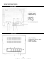
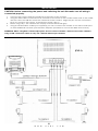
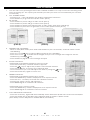
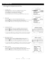
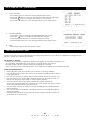
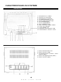
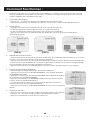
Instruction Manual
12" Quad System with 4 B/W CCD Cameras
Manuel D'Instruction
Système de quadruple de 12"avec 4 appareils-photo
de CCD de B/W
Q1204
now you can see
www.svat.com
TABLE OF CONTENTS
ENGLISH
PAGE #
Table Of Contents . . . . . . . .
Introduction / Whats Included
System Features . . . . . . . . .
Installation . . . . . . . . . . . . .
Wiring Diagram . . . . . . . . . .
How To Operate . . . . . . . . .
System Setup . . . . . . . . . . .
Troubleshooting . . . . . . . . . .
Specifications . . . . . . . . . . .
Warranty . . . . . . . . . . . . . . .
.
.
.
.
.
.
.
.
.
.
.
.
.
.
.
.
.
.
.
.
.
.
.
.
.
.
.
.
.
.
.
.
.
.
.
.
.
.
.
.
.
.
.
.
.
.
.
.
.
.
.
.
.
.
.
.
.
.
.
.
.
.
.
.
.
.
.
.
.
.
.
.
.
.
.
.
.
.
.
.
.
.
.
.
.
.
.
.
.
.
.
.
.
.
.
.
.
.
.
.
.
.
.
.
.
.
.
.
.
.
.
.
.
.
.
.
.
.
.
.
.
.
.
.
.
.
.
.
.
.
.
.
.
.
.
.
.
.
.
.
.
.
.
.
.
.
.
.
.
.
.
.
.
.
.
.
.
.
.
.
.
.
.
.
.
.
.
.
.
.
.
.
.
.
.
.
.
.
.
.
.
.
.
.
.
.
.
.
.
.
.
.
.
.
.
.
.
.
.
.
.
.
.
.
.
.
.
.
.
.
.
.
.
.
.
.
.
.
.
.
FRANCAIS
.
.
.
.
.
.
.
.
.
.
.
.
.
.
.
.
.
.
.
.
.
.
.
.
.
.
.
.
.
.
.
.
.
.
.
.
.
.
.
.
.
.
.
.
.
.
.
.
.
.
.
.
.
.
.
.
.
.
.
.
.
.
.
.
.
.
.
.
.
.
.
.
.
.
.
.
.
.
.
.
.
.
.
.
.
.
.
.
.
.
.
.
.
.
.
.
.
.
.
.
.
.
.
.
.
.
.
.
.
.
.
.
.
.
.
.
.
.
.
.
.
.
.
.
.
.
.
.
.
.
.
.
.
.
.
.
.
.
.
.
.
.
.
.
.
.
.
.
.
.
.
.
.
.
.
.
.
.
.
.
.
.
.
.
.
.
.
.
.
.
.
.
.
.
.
.
.
.
.
.
2
3
4
5
5
6
7
8
9
10
PAGE #
Introduction/Ce qui Est Inclus . . . . . . . . . . . . . . . . . . . . . . . . . . . . . . . . . . . . . . . . 11
Caractéristiques du système . . . . . . . . . . . . . . . . . . . . . . . . . . . . . . . . . . . . . . . . 12
Installation . . . . . . . . . . . . . . . . . . . . . . . . . . . . . . . . . . . . . . . . . . . . . . . . . . . . . 13
Diagramme De câblage . . . . . . . . . . . . . . . . . . . . . . . . . . . . . . . . . . . . . . . . . . . 13
Comment Fonctionner . . . . . . . . . . . . . . . . . . . . . . . . . . . . . . . . . . . . . . . . . . . . 14
Installation De Système . . . . . . . . . . . . . . . . . . . . . . . . . . . . . . . . . . . . . . . . . . . 15
Dépannage . . . . . . . . . . . . . . . . . . . . . . . . . . . . . . . . . . . . . . . . . . . . . . . . . . . . . 16
Caractéristiques . . . . . . . . . . . . . . . . . . . . . . . . . . . . . . . . . . . . . . . . . . . . . . . . . 17
Garantie . . . . . . . . . . . . . . . . . . . . . . . . . . . . . . . . . . . . . . . . . . . . . . . . . . . . . . . 18
2
w w w . s v a t . c o m
INTRODUCTION
Congratulations on your purchase of SVAT’s ClearVu Q1204. You will soon
find out that this product has many applications, some that we may not
even have mentioned. The following instruction manual will go over your
products, its features, and how to install it. Please read over all of the
instructions and maintenance information so you can extend the life of
this great product.
For more information on your wired security system and on any other
SVAT product, visit www.svat.com.
Please note that SVAT does not endorse any applications of this unit for any illegal activities.
What's included:
The following components should be included with your system. Please
check that you have them all before beginning installation:
A: 12” B/W Monitor
B: 4x B/W CCD Cameras with Stand
C: 18V Power Adapter
D: 5x BNC to RCA Connectors
E: 4x 60 feet Of DIN to DIN Cable
Not Shown: Warning Stickers, Warranty Registration, Crime Stoppers insert,
and Manual
A
B
D
E
C
*Actual Product May Not Be Exactly As Shown
3
w w w . s v a t . c o m
SYSTEM FEATURES
FRONT VIEW
1. V-HOLD control
2. Brightness control
3. Contrast control
4. MODE/ENTER key
5. FREEZE/VCR key
6. AUTO key
7. ZOOM/SETUP key
8. CH1/ key
9. CH2/ key
10. CH3/ key
11. CH4/ key
12. Power Indicator LED
13. Power On/Off Switch
BACK VIEW
1.
2.
3.
4.
5.
DC Power Input
Video Input (DIN)
VCR Output: Video Out (BNC)
VCR Input (BNC)
Video Input (BNC)
4
w w w . s v a t . c o m
INSTALLATION
CAUTION: Before connecting the power and switching the unit ON make sure all wiring is
connected properly.
1.
2.
4.
5.
Connect the power adapter (supplied) to the back of the monitor.
Using the DIN cable connect the four cameras to the back of the monitor. Both ends of the cable
are the same and will fit in both the camera and the monitor. Align the pins on the connection
jack, do not force the plug in, it should go in freely. (FIG-1)
When using only 1-2-3 cameras the empty channel will remain grey.
Using a standard RCA Cable (not supplied) you can connect the monitor to an extra monitor/vcr
or add additional cameras (use the BNC adapters provided to convert the BNC slots to RCA)
WARNING: When using BNC camera input jacks do not connect another camera to the same channel
using a DIN connection. There is only one camera allowed per channel.
WIRING DIAGRAM
(FIG-1)
5
w w w . s v a t . c o m
HOW TO OPERATE
1.
2.
3.
Turn the unit on by pressing in the button marked POWER. You may encounter a buzzing noise
when powering up. The system just reminds you that you have unused channels (no camera
connected)
FULL SCREEN MODE:
- Pressing CH1 - 4 key will display the desired channel in full screen
- Press MODE key to go back to QUAD mode (FIG-2)
PIP MODE:
- Press MODE key once will go to PIP1 mode (FIG-3)
- Press MODE key twice will go to PIP2 mode (FIG-4)
- Press MODE key three times will go back to PIP1 mode (with auto switching)
- Press MODE key four times to go back to the main QUAD screen (FIG-2)
(FIG-2)
(FIG-3)
(FIG-4)
4.
DEFINING PIP CHANNELS:
- When in PIP1/PIP2 mode press and hold MODE key for 2-3 seconds, channel name should
start blinking
- Press CH1 or CH2
key to select different picture for CHANNEL 1
- Press CH3 or CH4
to switch left and right and you can change the image for the PIP
windows by pressing
key
- Press MODE key again to save settings and quit
5.
ZOOM FUNCTION:
*Performed in QUAD/PIP1/PIP2/FULL screen mode:
- Press the ZOOM key, a ZOOM window appears
- Press the
key to adjust the position of the ZOOM window
- Press the ENTER key to zoom in the selected area
- Once zoomed in you can still adjust the area by using the
- Press the ZOOM key again to zoom out
6.
key
FREEZE FUNCTION:
*Performed in QUAD/PIP1/PIP2 screen mode:
- Press the FREEZE key, F1234 is displayed in the top left corner
- Press the CH1 - CH4 keys to freeze the desired camera.
- Pressing the same CH key will unfreeze it
- Press FREEZE again to unfreeze all cameras
*Performed in FULL screen mode:
- Press the FREEZE key, F1234 is displayed in the top left corner
- Press FREEZE again to unfreeze current camera
7.
AUTO SWITCHING FUNCTION:
- Press the AUTO key, signal will automatically switch between QUAD-CH1-CH2-CH3-CH4-QUAD
- Press the MODE key to disable auto switching and go back to QUAD mode
(Time delay can be adjusted in SYSTEM SETUP, see below)
6
w w w . s v a t . c o m
SYSTEM SETUP
* Press and hold the SETUP key for 2-3 seconds
* Use the
keys to navigate through the menus
1.
CAMERA TITLE
- Press SETUP key to enter the CAMERA TITLE sub-menu
- Press the key to choose the desired camera
- Use the
key to change the characters
- To move to the next character use the key
- Press the SETUP key to save and go back to the main menu
2.
TIME/DATE
- Press SETUP key to enter the TIME/DATE sub-menu
- Press the
keys to choose year/month/day/hour/minute/second
- Press the
keys to change the value of each item
- Press the SETUP key to save and go back to the main menu
3.
CONTRAST ADJUST
- Press SETUP key to enter the CONTRAST ADJUST sub-menu
- Press the
keys to choose desired camera channel
- Press the
keys to change the contrast of each camera
- Press the SETUP key to save and go back to the main menu
* You can also adjust the contrast of all for cameras by using the
control knob found under the flap on the front of the monitor
4.
BRIGHTNESS ADJUST
- Press SETUP key to enter the BRIGHTNESS ADJUST sub-menu
- Press the
keys to choose desired camera channel
- Press the
keys to change the brightness of each camera
- Press the SETUP key to save and go back to the main menu
* You can also adjust the brightness of all for cameras by using the
control knob found under the flap on the front of the monitor
5.
DISPLAY MODE
- Press SETUP key to enter the DISPLAY MODE sub-menu
- Press the
keys to choose desired item that needs adjusting
- Press the
keys to change the value of each item
- Press the SETUP key to save and go back to the main menu
7
w w w . s v a t . c o m
SYSTEM SETUP (continued)
6.
AUTO ADJUST
- Press SETUP key to enter the AUTO ADJUST sub-menu
- Press the
keys to choose desired item that needs adjusting
- Press the
keys to change the value of each item
- Press the SETUP key to save and go back to the main menu
7.
ALARM HISTORY
- Press SETUP key to enter the ALARM HISTORY sub-menu
- Press the
keys to scroll through different pages
- Press the MODE button to clear the history records
- Press the SETUP key to save and go back to the main menu
8.
EXIT
- Press SETUP key to exit the system setup
TROUBLESHOOTING
Please read this manual carefully before using this product. If you have any difficulties using this unit,
please consult the following checklist.
No Picture or Sound:
- Make sure the power adapter is properly plugged in. LED light should be on.
- Try adjusting the brightness as it may be turned all the way down.
- Double check all the camera wiring is plugged in correctly.
- Press any of the four channel buttons CH1-CH4 to turn switch to a desired camera.
Care and maintenance
• Keep all parts and accessories out of reach of young children.
• Do not attempt to open the case. Non-expert handling of the device
may damage it.
• Do not use or store in dusty, dirty or moist areas. This is an indoor unit.
• Do not store in hot areas. High temperatures can shorten the life of
electronic devices and warp or melt certain plastics.
• Do not store in very cold areas. When the system warms up
(to its normal temperature), moisture can form inside the case, which
may damage electronic circuit boards.
• Do not drop, knock, or shake it. Rough handling can break internal
circuit boards.
• Do not use harsh chemicals, cleaning solvents, or strong detergents
when cleaning.
• Operate this product using only the power supply included with it or
provided as an accessory.
8
w w w . s v a t . c o m
SPECIFICATIONS
Monitor (12” Quad)
Video input . . . . . . . . . . . . . . . . . . . . . . . . .
Video output . . . . . . . . . . . . . . . . . . . . . . . .
Display Modes: . . . . . . . . . . . . . . . . . . . . . .
......................
......................
......................
......................
PIP window . . . . . . . . . . . . . . . . . . . . . . . . .
Zoom . . . . . . . . . . . . . . . . . . . . . . . . . . . . . .
Video Feeze . . . . . . . . . . . . . . . . . . . . . . . .
Timer . . . . . . . . . . . . . . . . . . . . . . . . . . . . . .
A/V Loss Detection . . . . . . . . . . . . . . . . . . .
Alarm Record . . . . . . . . . . . . . . . . . . . . . . .
Picture Update . . . . . . . . . . . . . . . . . . . . . .
Standard Video Format . . . . . . . . . . . . . . .
Resolution (H x V) . . . . . . . . . . . . . . . . . . . .
....................
Power Supply . . . . . . . . . . . . . . . . . . . . . . .
Power Output For Camera . . . . . . . . . . . . .
Power Consumption . . . . . . . . . . . . . . . . . .
Weight . . . . . . . . . . . . . . . . . . . . . . . . . . . . .
Operating Temperature . . . . . . . . . . . . . . .
4 channels CVBS input 1Vp-p/75 Ohm
1 channel CVBS output 1Vp-p/75 Ohm
Single
Quad
Picture in Picture
ZOOM
AUTO Sequence (1-60 sec)
1 or 2
2x (position can be adjusted)
Support
Built in Real Time Clock
Support
Support
30frames/sec (EIA)
EIA 762x525 @ 30 frames per sec
Quad Mode 320 x 240
Full Mode 640 x 480
18V DC 2400mA
12V
<35W
14.5Kg
0-45 C
Camera (ClearVu 30)
Image sensor . . . . . . . . . . . . . . . . . . . . . . . .
Resolution . . . . . . . . . . . . . . . . . . . . . . . . . . .
Infrared LEDS . . . . . . . . . . . . . . . . . . . . . . . .
Lens . . . . . . . . . . . . . . . . . . . . . . . . . . . . . . .
Effective Pixels . . . . . . . . . . . . . . . . . . . . . . .
.......................
Min Illumination . . . . . . . . . . . . . . . . . . . . . .
Electronic Shutter . . . . . . . . . . . . . . . . . . . .
Signal/Noise Ratio . . . . . . . . . . . . . . . . . . . .
Video Out . . . . . . . . . . . . . . . . . . . . . . . . . .
Audio Out . . . . . . . . . . . . . . . . . . . . . . . . . .
Camera Input . . . . . . . . . . . . . . . . . . . . . . .
Camera Power Consumption . . . . . . . . . . .
Weight . . . . . . . . . . . . . . . . . . . . . . . . . . . . .
Operating Temperature . . . . . . . . . . . . . . .
1/3 CCD B/W Lens
420 TV Lines
12
6 mm
CCIR: 500 x 582
EIA: 512 x 492
0.1 LUX @ F1.2
1/60-1/10,000
48 dB
1.0Vp-p 75Ohm
0.5Vp-p 10k Ohm
12V DC
1.5W
0.3Kg
0-45 C
9
w w w . s v a t . c o m
PRODUCT WARRANTY
We take quality very seriously. This is why all of our products
come with a one year warranty from the original purchase date
against defects in workmanship and materials.
If you have warranty or support issues please contact us using any of the following methods:
SVAT Electronics USA
2315 Whirlpool St., Unit 333
NIagara Falls, New York
USA 14305
SVAT Electronics Canada
4080 Montrose Road
Niagara Falls, ON
Canada L2H 1J9
Phone: 866.946.7828
Fax: 888.771.1701
Email: [email protected]
Website: www.svat.com
Warranty Terms
1. SVAT products are guaranteed for a period of one year from the date of purchase against defects in
workmanship and materials. This warranty is limited to the repair, replacement or refund of the purchase price
at SVAT's option.
2. When service is required, the warranty is validated by the submission of a fully completed warranty card.
3. This warranty becomes void if the product shows evidence of having been misused, mishandled or tampered
with contrary to the applicable instruction manual.
4. Routine cleaning, normal cosmetic and mechanical wear and tear are not covered under the terms of this
warranty.
5. The warranty expressly provided for herein is the sole warranty provided in connection with the product itself
and no other warranty, expressed or implied is provided. SVAT assumes no responsibilities for any other
claims not specifically mentioned in this warranty.
6. This warranty does not cover the shipping cost, insurance or any other incidental charges.
7. You MUST call SVAT before sending any product back for repair. You will be given a Return Authorization
number. When returning the product for warranty service, please pack it carefully in the original box with all
supplied accessories, and enclose your original receipt or copy, and a brief explanation of the problem
(include RA #).
8. This warranty is valid only in Canada and the U.S.A.
9. This warranty card cannot be re-issued.
CAUTION
RISK OF ELECTRIC SHOCK, DO NOT OPEN
TO REDUCE THE RISK OF ELECTRIC SHOCK, DO NOT REMOVE THE COVER (BACK).
NO USER SERVICEABLE PARTS INSIDE. REFER SERVICING TO
QUALIFIED SERVICE PERSONNEL.
Graphic Symbol Explanation:
The lightning flash with arrowhead symbol, within an equilateral triangle, is intended to
alert the user to the presence of uninsulated “dangerous voltage” within the product’s
enclosure that may be of sufficient magnitude to constitute a risk of electric shock to persons.
The exclamation point within an equilateral triangle is intended to alert the user to the
presence of important operating maintenance (servicing) instructions in the literature
accompanying the appliance.
WARNING: TO PREVENT FIRE OR SHOCK HAZARDS, DO NOT EXPOSE THIS UNIT
TO RAIN OR MOISTURE
10
w w w . s v a t . c o m
INTRODUCTION
Félicitations sur votre achat de ClearVu Q4 de SVAT. Vous découvrirez
bientôt que ce produit a beaucoup d'applications, certains que nous
avons pu même ne pas avoir mentionnés. Le manuel d'instruction suivant
ira au-dessus de vos produits, ses dispositifs, et comment l'installer.
L'excédent svp lu tout des instructions et de l'information d'entretien ainsi
de vous peut prolonger la vie de ce grand produit.
Pour plus d'information sur votre système de câble de sécurité et sur tout
autre produit de SVAT, visite www.svat.com
Veuillez noter que SVAT n'approuve aucune application de cette unité pour aucune activité illégale
Ce qui est inclus :
Les composants suivants devraient être inclus avec votre système.
Veuillez vérifier que vous les avez tous avant de beginning l'installation :
A: Moniteur De 12"B/W
B: appareils-photo de CCD de 4x B/W avec le stand
C: Adapteur De la Puissance 18V
D: 5x BNC aux connecteurs de RCA
E: 4x 60 pieds de DIN au DIN câblent
Non montré : Autocollants, enregistrement de garantie, insertion de taquets
de crime, et manuel d'avertissement
A
B
D
E
C
* Le Produit Réel Peut Ne pas être Exactement Comme Montré
11
w w w . s v a t . c o m
CARACTÉRISTIQUES DU SYSTÈME
VUE DE FACE
1. Commande de V-HOLD
2. Contrôle de luminosité
3. Commande de contraste
4. Le MODE/ÉCRIVENT la clef
5. Clef du GEL/magnétoscope
6. Clef AUTOMATIQUE
7. Clef de ZOOM/SETUP
8. CH1/ LÈVENT la clef
9. CH2/ verouillent VERS LE BAS
10. CH3/ Clef GAUCHE
11. CH4/ BONNE clef
12. Indicateur De Puissance LED
13. Commutateur "marche- arrêt"
VUE ARRIÈRE
1. Entrée D'Alimentation CC
2. Entrée Visuelle (DIN)
3. Le Magnétoscope A produit : Vidéo
Dehors (BNC)
4. Entrée de Magnétoscope (BNC)
5. Entrée Visuelle (BNC)
12
w w w . s v a t . c o m
INSTALLATION
ATTENTION : Avant de relier la puissance et commuter l'unité assurez-vous DESSUS que tout
le câblage est relié correctement.
1.
2.
4.
5.
Reliez l'adapteur de puissance (fourni) au dos du moniteur.
En utilisant le câble DIN reliez les quatre appareils-photo au dos du moniteur. Les deux extrémités
du câble sont identiques et s'adapteront dans l'appareil-photo et le moniteur. Alignez les
goupilles sur le cric de raccordement, ne forcez pas la prise dedans, il devrait entrer librement.
(FIG-1)
Quand en utilisant seulement 1-2-3 appareils-photo le canal vide demeurera gris.
En utilisant un câble standard de RCA (non fourni) vous pouvez relier le moniteur à un monitor/vcr
supplémentaire ou ajouter les appareils-photo additionnels (utilisez les adapteurs de BNC fournis
pour convertir les fentes de BNC en RCA)
AVERTISSEMENT : En utilisant l'appareil-photo de BNC entrez les crics ne relient pas un autre appareilphoto au même canal en utilisant un raccordement DIN. Il y a seulement un appareil-photo permis par
canal.
DIAGRAMME DE CÂBLAGE
(FIG-1)
13
w w w . s v a t . c o m
Comment Fonctionner :
1.
Tournez l'unité dessus en renversant le commutateur à "I" position.You peut rencontrer un long
bruit de ronflement en mettant sous tension. Le système vous rappelle juste que vous avez les
canaux inutilisés (pas appareil-photo relié)
2.
MODE DE PLEIN ÉCRAN :
- serrant CH1 - la clef 4 montrera le canal désiré dans le plein écran
- appuyez sur la touche de MODE pour aller de nouveau au mode de QUADRUPLE (FIG-2)
3.
MODE DE PIP :
- appuyez sur la touche de MODE une fois ira au mode PIP1 (FIG-3)
- la clef de MODE de pression deux fois ira au mode PIP2 (FIG-4)
- la clef de MODE de pression trois fois ira de nouveau au mode PIP1
- appuyez sur la touche de MODE quatre fois d'aller de nouveau à l'écran principal de
QUADRUPLE (FIG-2).
(FIG-2)
(FIG-3)
(FIG-4)
4.
DÉFINIR DES CANAUX DE PIP:
- quand dans la clef de MODE de pression et de prise du mode PIP1/PIP2 pendant 2 ou 3 en sec
ond lieu, nom de canal devrait commencer à clignoter
- appuyez sur la touche CH1 ou CH2 HAUT/BAS pour choisir le picture différent pour la MANCHE 1
- serrez CH3 ou CH4 LEFT/RIGHT à commuter à gauche et à droite et vous peut changer l'image
pour les fenêtres de PIP par clef HAUT/BAS de pression
- appuyez sur la touche de MODE encore pour sauver des arrangements et pour stopper
5.
FONCTION DE BOURDONNEMENT :
* Exécuté dans le mode d'écran de QUAD/PIP1/PIP2/FULL :
- appuyez sur la touche de BOURDONNEMENT, une fenêtre de BOUR
DONNEMENT apparaît
- appuyez sur la touche d'UP/DOWN/LEFT/RIGHT pour ajuster la position
de la fenêtre de BOURDONNEMENT
- appuyez sur la touche de PÉNÉTRER DANS pour bourdonner dans le
secteur choisi UP/DOWN/LEFT/RIGHT
- une fois bourdonné dans vous peut immobile ajuster le secteur en
employant la clef d'UP/DOWN/LEFT/RIGHT
- appuyez sur la touche de BOURDONNEMENT encore pour bourdonner
dehors
6.
FONCTION DE GEL :
- appuyez sur la touche de GEL, F1234 est montré dans le coin gauche
- serrez le CH1 - les clefs CH4 pour geler l'appareil-photo désiré.
- appuyer sur la même touche de ch unfreeze la
14
w w w . s v a t . c o m
COMMENT FONCTIONNER (suite)
* Exécuté dans le mode de PLEIN écran :
- Appuyez sur la touche de GEL, F1234 est montré dans le coin gauche supérieur
- Serrez le GEL encore pour unfreeze l'appareil-photo courant
7.
FONCTION DE COMMUTATION AUTOMATIQUE :
- Appuyez sur la touche AUTOMATIQUE, signal commutera automatically entre QUAD-CH1-CH2CH3-CH4-QUAD
- Appuyez sur la touche AUTOMATIQUE encore pour neutraliser la commutation automatique
(délai peut être ajusté dans l'INSTALLATION de SYSTÈME, voient ci-dessous)
INSTALLATION DE SYSTÈME
* Appuyez sur et tenez la touche d'INSTALLATION pendant 2 ou 3 secondes
* Employez les clefs HAUT/BAS pour diriger par les menus
1.
TITRE D'APPAREIL-PHOTO
- Serrez POUR INSTALLER la clef pour écrire le sous-menu de TITRE
d'APPAREIL-PHOTO
- Appuyez sur VERS LE BAS le touche pour choisir l'appareil-photo
désiré
- Employez la clef de LEFT/RIGHT pour changer les caractères
- Pour se déplacer au prochain caractère employez la clef HAUTE
- Serrez POUR INSTALLER la clef pour sauver et aller de nouveau au
menu principal
2.
HEURE/DATE
- Serrez POUR INSTALLER la clef pour écrire le sous-menu de
TIME/DATE
- Appuyez sur les touches de LEFT/RIGHT pour choisir
l'année/mois/jour/heure/minute/en second lieu
- Appuyez sur les touches de DOWN/UP pour changer la valeur de
chaque article
- Serrez POUR INSTALLER la clef pour sauver et aller de nouveau au
menu principal
3.
LE CONTRASTE S'AJUSTENT
- La clef d'INSTALLATION de pression pour écrire le CONTRASTE
AJUSTENT le sous-menu
- Appuyez sur les touches HAUT/BAS pour choisir le canal désiré
d'appareil-photo
- Appuyez sur les touches de LEFT/RIGHT pour changer le contraste
de chaque appareil-photo
- Serrez POUR INSTALLER la clef pour sauver et aller de nouveau au
menu principal
4.
L'ÉCLAT S'AJUSTENT
- La clef d'INSTALLATION de pression pour écrire l'ÉCLAT AJUSTENT le
sous-menu
- Appuyez sur les touches HAUT/BAS pour choisir le canal désiré
d'appareil-photo
- Appuyez sur les touches de LEFT/RIGHT pour changer l'éclat de
chaque appareil-photo
- Serrez POUR INSTALLER la clef pour sauver et aller de nouveau au
menu principal
15
w w w . s v a t . c o m
INSTALLATION de SYSTÈME (suite)
5.
MODE D'AFFICHAGE
- Serrez POUR INSTALLER la clef pour écrire le sous-menu de MODE
d'AFFICHAGE
- Appuyez sur les touches HAUT/BAS pour choisir l'article désiré qui a
besoin s'ajuster
- Appuyez sur les touches de LEFT/RIGHT pour changer la valeur de
chaque article
- Serrez POUR INSTALLER la clef pour sauver et aller de nouveau au
menu principal
6.
L'AUTOMOBILE S'AJUSTENT
- La clef d'INSTALLATION de pression pour entrer dans l'AUTOMOBILE
AJUSTENT le sous-menu
- Appuyez sur les touches HAUT/BAS pour choisir l'article désiré qui a
besoin s'ajuster
- Appuyez sur les touches de LEFT/RIGHT pour changer la valeur de
chaque article
- Serrez POUR INSTALLER la clef pour sauver et aller de nouveau au
menu principal
7.
HISTOIRE D'ALARME
- Serrez POUR INSTALLER la clef pour écrire le sous-menu d'HISTOIRE
d'ALARME
- Appuyez sur les touches HAUT/BAS pour faire défiler par
différentes pages
- Appuyez sur le bouton de MODE pour dégager les
enregistrements historiques
- Serrez POUR INSTALLER la clef pour sauver et aller de nouveau au
menu principal
8.
SORTIE
- Serrez POUR INSTALLER la clef pour sortir l'installation de système
DÉPANNAGE
Veuillez lire ce manuel soigneusement avant d'employer ce produit. Si vous avez n'importe quelles difficultés en utilisant cette unité, consultez svp la liste de contrôle suivante.
Aucune image ou bruit :
- assurez-vous que l'adapteur de puissance est correctement branché. La lumière de LED devrait être
allumée.
- essayez d'ajuster l'éclat comme ce peut être tourné toute la manière vers le bas.
- le double contrôle tout le câblage d'appareil-photo est branché correctement.
- appuyez sur n'importe lequel de ces quatre boutons CH1-CH4 de canal pour tourner le commutateur à
un appareil-photo désiré.
Soin et entretien
• Maintenez tous les pièces et accessoires hors de portée des enfants en bas âge.
• N'essayez pas d'ouvrir la valise. la manipulation d'Non-expert du dispositif peut l'endommager.
• N'employez pas ou pas entreposé dans des secteurs poussiéreux, sales ou moites. C'est une unité
d'intérieur.
• Pas entreposé dans des secteurs chauds. Les températures élevées peuvent raccourcir la vie des
dispositifs électroniques et déformer ou fondre certains plastiques.
• Pas entreposé dans des secteurs très froids. Quand le système réchauffe (à sa température normale),
l'humidité peut former à l'intérieur du cas, qui peut endommager les cartes électroniques.
• Ne le laissez pas tomber, ne frappez pas, ou ne secouez pas. Une manipulation peu soigneuse peut
casser les cartes internes.
• N'employez pas les produits chimiques durs, les dissolvants de nettoyage, ou les détergents forts en
nettoyant.
• Actionnez ce produit en utilisant seulement l'alimentation d'énergie incluse avec elle ou si comme
accessoire.
16
w w w . s v a t . c o m
CARACTÉRISTIQUES
Moniteur (12 "Quadruple)
Entrée visuelle . . . . . . . . . . . . . . . . . . . . . . .
Rendement visuel . . . . . . . . . . . . . . . . . . . .
Modes D'Affichage . . . . . . . . . . . . . . . . . .
......................
......................
......................
......................
Fenêtre de PIP . . . . . . . . . . . . . . . . . . . . . .
Bourdonnement . . . . . . . . . . . . . . . . . . . . .
Feeze Visuel . . . . . . . . . . . . . . . . . . . . . . . .
Temporisateur . . . . . . . . . . . . . . . . . . . . . . .
Détection De Perte d'A/V . . . . . . . . . . . . .
Disque D'Alarme . . . . . . . . . . . . . . . . . . . . .
Mise à jour D'Image . . . . . . . . . . . . . . . . . .
Format Visuel Standard . . . . . . . . . . . . . . .
Résolution (H X V) . . . . . . . . . . . . . . . . . . . .
....................
Alimentation D'Énergie . . . . . . . . . . . . . . . .
Rendement De Puissance . . . . . . . . . . . . . .
Puissance D'Énergie . . . . . . . . . . . . . . . . . .
Poids . . . . . . . . . . . . . . . . . . . . . . . . . . . . . .
Temperature Fonctionnant . . . . . . . . . . . .
4 canaux CVBS Entrée 1Vp-p/75 Ohm
1 canaux CVBS Rendement 1Vp-p/75 Ohm
Simple
Quadruple
Image dans l'image
BOURDONNEMENT
Ordre AUTOMATIQUE (1-60 sec)
1 or 2
2x (la position peut être ajustée)
Appui
Construit dans l'horloge en temps réel
Appui
Appui
30armatures/sec (EIA)
EIA 762x525 @ 30 armatures par sec
Quadruple Mode 320 x 240
Complètement Mode 640 x 480
18V DC 2400mA
12V
<35W
14.5Kg
0-45 C
Appareil-photo(ClearVu 30)
Sonde d'image . . . . . . . . . . . . . . . . . . . . . .
Résolution . . . . . . . . . . . . . . . . . . . . . . . . . . .
LED Infrarouges . . . . . . . . . . . . . . . . . . . . . .
Objectif . . . . . . . . . . . . . . . . . . . . . . . . . . . .
Pixel Efficaces . . . . . . . . . . . . . . . . . . . . . . .
.......................
Illumination Min . . . . . . . . . . . . . . . . . . . . . .
Obturateur Électronique . . . . . . . . . . . . . .
Rapport De Signal/Bruit . . . . . . . . . . . . . . . .
Vidéo Dehors . . . . . . . . . . . . . . . . . . . . . . .
Acoustique Dehors . . . . . . . . . . . . . . . . . . .
Entrée D'Appareil-photo . . . . . . . . . . . . . . .
Puissance D'Énergie . . . . . . . . . . . . . . . . . . .
Poids . . . . . . . . . . . . . . . . . . . . . . . . . . . . . .
Temperature Fonctionnant . . . . . . . . . . . .
1/3 CCD B/W Objectif
420 Lignes de TV
12
6 mm
CCIR: 500 x 582
EIA: 512 x 492
0.1 LUX @ F1.2
1/60-1/10,000
48 dB
1.0Vp-p 75Ohm
0.5Vp-p 10k Ohm
12V DC
1.5W
0.3Kg
0-45 C
17
w w w . s v a t . c o m
GARANTIE DE PRODUIT
Nous prenons la qualité très sérieusement. C'est pourquoi tous
nos produits viennent avec une garantie d'un an de la date originale d'achat contre des défauts en exécution et matériaux.
Si vous avez les issues de garantie ou de soutien satisfont nous contactent employant n'importe laquelle
des méthodes suivantes :
SVAT Electronics USA
2315 Whirlpool St., Unit 333
NIagara Falls, New York
USA 14305
SVAT Electronics Canada
4080 Montrose Road
Niagara Falls, ON
Canada L2H 1J9
Phone: 866.946.7828
Fax: 888.771.1701
Email: [email protected]
Website: www.svat.com
Limites De Garantie
1. Les produits de SVAT sont garantis pour une période d'une année de la date d'achat contre défectuosités
l'exécution et défectuosité des matériels. Cette garantie est limitée à la réparation, le remplacement ou le
remboursement du prix d'achat à l'option de SVAT.
2. Quand le service est exigé, la garantie est validée par la soumission d'une carte de garantie entièrement
complétée.
3. Cette garantie devient vide si le produit montre l'évidence d'ayant été employé improprement, malmené ou a
altéré contraire au manuel d'instruction applicable.
4. Le nettoyage de routine, l'usure normale normal, cosmétique et mécanique n'est pas couverte sous les ter
mes de cette garantie.
5. La garantie a pourvu expressément à en ceci est la garantie seule fournie à propos du produit lui-même e
aucune autre garantie, exprimée ou suggérée est fournie. SVAT ne suppose pas de responsabilités pour les
autres réclamations pas en particulier mention né dans cette garantie.
6. Cette garantie ne couvre pas le coût expédiant, l'assurance ou les autres charges accessoires.
7. En retournant le produit pour le service de garantie, s'il vous plaît l'emballer soigneusement dans la boîte
originale avec tous accessoires fournis, et enclore votre carte de garantie, le reçu original ou la copie, et une
explication brève du problème.
8. Cette garantie est valide seulement dans le Canada et les ETATS-UNIS.
9. Cette carte de garantie ne peut pas être la réédition.
ATTENTION
LE RISQUE DE DÉCHARGE ÉLECTRIQUE, NE S'OUVRENT PAS
POUR RÉDUIRE LE RISQUE DE DÉCHARGE ÉLECTRIQUE, N'ENLEVEZ PAS LA COUVERTURE (ARRIÈRE). AUCUNES PIÈCES DE L'UTILISATEUR SERVICEABLE À L'INTÉRIEUR.
RÉFÉREZ-VOUS L'ENTRETIEN AU PERSONNEL DE SERVICE QUALIFIÉ.
Explication Graphique De Symbole :
Le flash de foudre avec le symbole de pointe de flèche, dans une triangle equilateral, est
prévu pour alerter l'utilisateur à la présence "de la tension dangereuse" non isolée dans la
clôture du produit qui peut être de la grandeur suffisante pour constituer un risque de
décharge électrique aux personnes.
Le point d'exclamation dans une triangle equilateral est prévu pour alerter l'utilisateur à la
présence des instructions de fonctionnement importantes d'entretien (entretien) dans la
littérature accompagnant l'appareil.
AVERTISSEMENT : POUR EMPÊCHER DES RISQUES DU FEU OU DE CHOC, N'EXPOSEZ PAS CETTE UNITÉ À LA PLUIE OU À L'HUMIDITÉ
18
w w w . s v a t . c o m
www.svat.com
Disclaimer: SVAT does not endorse of any of SVAT products for any illegal activites.
SVAT is not responsible or liable in any way shape or form for any damage, vandalism,
theft or any other action that may occur while a SVAT product is in use by the purchaser.
Déni : SVAT n'approuve d'aucun de produits de SVAT pour aucun activites illégal. SVAT n'est pas
responsable ou responsable de quelque façon forme ou forme d'aucun dommage, de
vandalisme, de vol ou d'aucune autre action qui peuvent se produire tandis qu'un produit
de SVAT est en service par l'acheteur.