1
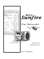
DIM - STANDBY
BRIGHT - ON
True Subwoofer
DIM - STANDBY
BRIGHT - ON
Signature and
Standard Edition
User's Manual
Safety Instructions
9. Power Cord Protection — Power-supply
cords should be routed so that they are
1. Read Instructions -– All the safety and
not likely to be walked upon or pinched by
operation instructions should be read before
items placed upon or against them, paying
the SunÞre Component is operated.
particular attention to cords at plugs, con2. Retain Instructions — The safety and
venience receptacles, and the point where
operating instructions should be kept for
they exit the Component.
future reference.
10. Cleaning — The Component should
3. Heed Warnings — All warnings on the
be cleaned only as recommended in this
Component and in these operating instrucmanual.
tions should be followed.
11. Non-use Periods—The power cord of
4. Follow Instructions — All operating and
the Component should be unplugged from
other instructions should be followed.
the outlet when unused for a long period
of time.
5. Water and Moisture — The Component should not be used near water - for
12. Object and Liquid Entry — Care
example, near a bathtub, washbowl, kitchen
should be taken so that objects do not fall
sink, laundry tub, in a wet basement, or near
into and liquids are not spilled into the ina swimming pool, etc. This Component is
side of the Component. Do not expose the
intended for use in Moderate climates. Do
Component to dripping or splashing from
not use in Tropical climates.
liquids. Do not place objects Þlled with
liquids on top of, or near the Component.
6. Ventilation — The Component should
For example, no vases, glasses of wine,
be situated so that its location or position
or cans of pop.
does not interfere with its proper ventilation.
Ensure a minimum distance of 2 inches
13. Damage Requiring Service — The
(5 cm) around the Component for sufÞcient
Component should be serviced only by
ventilation. For example, the Component
qualiÞed service personnel when:
should not be situated on a bed, sofa, rug,
A. The power-supply cord or the plug has
or similar surface that may block any ventibeen damaged; or
lation; or placed in a built-in installation such
B. Objects have fallen, or liquid has spilled
as a bookcase or cabinet that may impede
into the Component; or
the ßow of air. Ensure that the ventilation is
C.
The Component has been exposed to
not impeded by covering the control panel
rain; or
with items such as newspapers, table-cloths,
D. The Component does not appear to opercurtains, shaggy dogs, sleeping cats etc.
ate normally or exhibits a marked change
7. Heat and Flames — The Component
in performance; or
should be situated away from heat sources
E. The Component has been dropped, or its
such as radiators, or other devices which
cabinet damaged.
produce heat. Do not place naked ßame
sources, such as lighted candles on top of,
14. Servicing — The user should not ator near the Component.
tempt to service the Component beyond
those means described in this operating
8. Power Sources — The Component should
manual. All other servicing should be
be connected to a power supply only of the
referred to qualiÞed service personnel.
type described in these operation instructions or as marked on the Component.
2
User's Manual
15. To Prevent Electric Shock, do not
use this polarized plug with an extension
cord, receptacle or other outlet unless the
blades can be fully inserted to prevent
blade exposure.
Pour préevenir les chocs électriques ne
pas utiliser cette Þche polariseé avec un
prolongateur, un prise de courant ou une
autre sortie de courant, sauf si les lames
peuvent être insérées à fond sans laisser
aucune pariie à découvert.
16. Grounding or Polarization — Precautions should be taken so that the grounding or polarization means of the Component is not defeated.
This apparatus does not exceed the Class
A/Class B (whichever is applicable) limits
for radio noise emissions from digital apparatus as set out in the radio interference
regulations of the Canadian Department of
Communications.
ATTENTION — Le présent appareil numérique n'émet pas de bruits radioélectriques
dépassant las limites applicables aux appareils numériques de class A/de class B
(selon le cas) prescrites dans le règlement
sur le brouillage radioélectrique édicté
par les ministere des communications du
Canada.
WARNING:THIS SUBWOOFER IS CAPABLE OF PRODUCING
VERY HIGH SOUND PRESSURE LEVELS. YOU MUST TAKE
EVERY PRECAUTION TO PROTECT YOUR HEARING FROM
PERMANENT DAMAGE.
Contents
Safety Instructions.........................................2
Introduction ...................................................4
Features ........................................................4
Unpacking and Care .....................................4
Overview .......................................................5
Control Panel Features .................................6
Installation .....................................................9
Connections ................................................10
Location ......................................................11
Room Equalization Procedure ....................12
System ConÞgurations ................................14
Adjusting the Controls .................................18
SpeciÞcations (Signature Edition) ...............19
SpeciÞcations (Standard Edition) ................20
Troubleshooting Guide ................................21
Limited Warranty .........................................23
Service Assistance ......................................23
To Þnd out more about this and other SunÞre products,
please visit our website: www.sunÞre.com
User's Manual
3
Introduction
•
2,700 watt, high efÞciency ampliÞer
Thank you for purchasing my SunÞre
True Subwoofer EQ. I hope you enjoy
it and the music it makes as much as I
have enjoyed creating it for you.
•
High gloss, dark rosewood Þnish
•
Automatic Room Equalization mode
•
Measurement Microphone included
•
Very low distortion
The big breakthrough features of
the subwoofer are its uncanny tracking downconverter, its long throw, high
back-electromotive force driver, and its
fully automatic room equalizer. Taken
together, they provide this subwoofer with
as much bass as you could get from several 15 inch drivers mounted in a cabinet
the size of a small refrigerator.
•
Long throw, premium quality drivers
•
Stunning output from a small cube!
•
Automatic signal-sensing turn-on and
standby mode
•
12 VDC trigger input for remote turn-on
•
Balanced XLR input
•
Line level unbalanced inputs
•
Speaker level binding post inputs
•
Line level high-pass outputs
•
Continuously variable phase control
•
Continuously variable crossover frequency adjustment, 35 to 100 Hz
•
Continuously variable volume level
control
•
Soft clipping circuit allows graceful
overload and prevents speaker damage
due to clipping
•
Gold-plated inputs and outputs.
Dear Friend:
Unpacking
Your SunÞre Subwoofer should reach
you in perfect condition. If you do notice
any shipping damage, please contact
your SunÞre Dealer immediately.
Gently lift out the unit and remove all
the packing material. It is important to
save all the packing materials and the
box in case your subwoofer ever needs
to be moved or shipped for repair.
Make sure that you keep your sales
receipt. It is the only way to establish
the duration of your Limited Warranty
and it may come in useful for insurance
purposes.
Please take a moment to Þll out and
mail the SunÞre Customer Response
card. Also read the serial number located
on the control panel and record it here:
Serial Number:
Purchased from:
Date:
4
Features
Care
To maintain the speaker cabinet’s Þnish, Þrst unplug the power cord and then
use a soft cloth to clean the surfaces.
To keep the large rubber surrounds soft
and supple for 20 years or more, treat
them with MINK OIL, available at most
shoe repair stores. Unplug the power
cord, and rub a generous amount into the
surrounds with a soft cloth about once
a year (more often if you live in a dry
climate).
If your SunÞre Subwoofer needs servicing, please read the Troubleshooting
section on page 21. If a problem still
persists, contact your nearest authorized
SunÞre Dealer.
User's Manual
Overview
Your SunÞre True Subwoofer EQ is
designed to give you the best possible
low-frequency sound quality for your
Home Theater experience. It incorporates
a tremendously powerful built-in ampliÞer
and a pair of drivers to produce tight,
ßoor-rumbling, denture-rattling bass that
you can feel as well as hear.
The subwoofer is available in two versions, and this manual covers both:
Signature Edition is a 13 inch cube, with
an output greater than 116 dB peak
SPL, 16 Hz to 100 Hz.
Standard Edition is an 11 inch cube,
with an output greater than 110 dB
peak SPL, 18 Hz to 100 Hz.
The subwoofer has an automatic
equalization system which will tailor the
subwoofer output to compensate for any
room effects. It also has a manual equalization mode.
The subwoofer has an adjustable high
cut Þlter and a choice of speaker-level
or line-level inputs for easy incorporation
into existing systems, or as part of a
subwoofer/satellite speaker combination.
Controls for adjusting the volume,
crossover frequency and phase, allow
the subwoofer to be perfectly matched
to any listening environment and audio
components.
The Drivers
To have lots of bass requires moving
lots of air. Your SunÞre Subwoofer incorporates two drivers that can move back
and forth approximately Þve times more
than a normal subwoofer. This gives it a
lot of air moving capacity which allows for
majestic bass performance.
Two drivers share the acoustic output.
Sometimes one driver appears to be
moving more than the other. They both
move the same amount only when op-
User's Manual
erating at the limit of their excursion and
power output, or when bass requirements
and music requirements demand maximum output from the system. Otherwise,
the power is shared between the two
drivers in a way that depends on the momentary amplitude and the momentary
musical spectrum. It is normal for one or
the other to move more or less than its
mate during operation.
The AmpliÞer
The large movement range of the drivers creates greater air pressure inside
the box than a conventional subwoofer.
Therefore, the drive ampliÞer must be
much more powerful than an ordinary
subwoofer ampliÞer. In fact, it has to be
so powerful, it is almost hard to believe.
The power ampliÞer within your SunÞre
Subwoofer is capable of delivering over
2,700 watts into a 3.3 ohm resistor (the
driver voice coil resistance). When the
same full output is applied to the driver,
however, the enormous back-electromotive force generated as a consequence of its large motion and giant magnet, causes the current ßow to be much
less than if it were a 3.3 ohm resistor. It
is this singular property of the driver that
allows the subwoofer to be approximately
ten times more efÞcient than a subwoofer
this size would normally be.
A compressor circuit kicks in automatically if the input signal level reaches a
level that would overload the driver. This
maintains a ceiling on the output without
clipping. If the input signal is driven even
further, a ‘soft clipping’ circuit is enabled.
This allows the subwoofer to put more
sound into the room to satiate the power
hungry user, but without distortion or
damage to the subwoofer. Thus, for explosive scenes in movies, this produces
extremely high sound pressure levels
(SPL) in your room without the drivers
banging against the mechanical stops.
For more details of the subwoofer design, please call us or view our website:
www.sunÞre.com.
5
Control Panel Features
15
14
13
12
1
2
3
4
5
6
DIM - STANDBY
BRIGHT - ON
11
7
10
9
1. Volume
This control lets you match the output
level of the subwoofer to the level
of your satellite/main speakers. The
subwoofer output will increase as this
control is rotated clockwise. When you
have just installed your system, turn
this down Þrst before turning on your
subwoofer. This will prevent any loud
surprises.
2. Crossover Frequency
6
8
3. Phase Control
This control changes the relative phase
of the subwoofer with respect to your
other speakers. Use this control to help
blend the subwoofer with the rest of
your system. This is accomplished by
adjusting the control in small increments as you listen for the most bass
at your listening position. As a Þnal trim,
readjust the Crossover Frequency and
Volume controls after the Phase has
been set.
This controls the high frequency cutoff
point. With the control set to the 100
Hz mark, the subwoofer will reproduce
frequencies up to 100 Hz. If the control
is set fully clockwise, the crossover is
bypassed and the subwoofer will reproduce a wide frequency range. With
the control fully counter-clockwise the
subwoofer reproduces a narrow range,
up to 30 Hz.
4. Trigger Inputs
Rotate the control until the bass sounds
natural. If the mid-bass sounds natural
but you want more low bass, turn this
control down a little, then turn the
Volume control up by about the same
amount. This increases the low-bass
output while leaving the mid-bass
output the same.
5. Outputs
These two inputs can be used to automatically turn on the subwoofer. To do
this, connect 12 VDC to either of these
terminals. Some Home Theater preampliÞers, such as the SunÞre Theater
Grand II and III, have matching 12 VDC
Trigger outputs. When they are turned
on, the subwoofer will turn on.
Line level high-pass output signals
are available at these jacks. These
outputs are active whenever a signal
is hooked up to the line level inputs
of the subwoofer. This crossover is a
User's Manual
passive network with a Þxed crossover
frequency of 70 Hz and a 6 dB per
octave slope.
We recommend using this high-pass
function with main/satellite speakers
that are small and not designed to
reproduce low frequencies. If your main
speakers are capable of operating full
range, then you will not need to use the
high-pass function.
To use the high-pass outputs, connect
the preamp outs on your preamp/
receiver to the subwoofer’s line level inputs using good quality RCA type patch
cords. Then connect a second patch
cord from the subwoofer’s outputs to
the inputs of your main ampliÞer. This
will allow your main speakers to operate at frequencies above 70 Hz and the
subwoofer to operate at frequencies
below 70 Hz (see page 16).
6. Line Level Inputs
Connect these unbalanced inputs with
RCA type patch cords to the line level
outputs of your receiver or preamp.
If your preampliÞer or receiver has a
single sub/LFE output, connect it to
the subwoofer’s left input jack (see
page 14). There is no need to use the
subwoofer’s right input jack.
If you want to run your main/satellite
speakers full range, use a “Y” adapter
at the preampliÞer outputs (see page
15). In this way, you can send the
preampliÞer’s output signal to your
main ampliÞer and to the subwoofer at
the same time.
7. Balanced (XLR) Input
Use this balanced input to connect
to the balanced line-level output of a
Home Theater preampliÞer or other
source. Balanced connections offer
superior noise cancellation over unbalanced connections, so if your preamp
has an XLR subwoofer output, we
recommend using it.
User's Manual
8. Speaker Level Inputs
Under normal conditions, the preferred
connection is through the line level
inputs. If this is difÞcult or not possible
in your system, then you can use the
speaker level inputs. Also, if you experience excessive noise or hum with the
line level inputs, often a simple change
to the speaker level inputs will result in
a lower background noise level.
Connect the speaker level inputs to the
speaker-level outputs of your ampliÞer
or receiver using speaker wire. The
binding posts can accept bare wire,
banana, dual-banana or spade connections.
Your ampliÞer or receiver MUST
have common grounded outputs,
or it will be damaged if connected
to the subwoofer’s speaker level
inputs.
9. Line Fuse
The subwoofer is supplied with a conservative slow-blow type fuse to protect
the electronics.
Always unplug the power cord
before inspecting or changing the
fuse. Never use a fuse with a larger current rating than shown on the
markings next to the fuseholder.
10. IEC Linecord socket
The subwoofer comes with a detachable linecord which connects here.
US (120 VAC) MODEL: Connect
the linecord to the subwoofer before
connecting the other end to an 120
Volt, 60 Hz AC outlet. The outlet must
have a circuit rating of 8 amps or more
(a typical home circuit is rated at 15
amps).
Never plug the US (120 VAC)
Model subwoofer directly into
220-240 Volts AC as this will cause
catastrophic circuit failure.
7
Control Panel Features continued
15
14
13
12
DIM - STANDBY
BRIGHT - ON
11
EURO (230 VAC) MODEL: Connect
the linecord to the subwoofer before
connecting the other end to a 230 Volt,
50/60 Hz AC outlet. The outlet must
have a circuit rating of 8 amps or more.
Never plug the Euro (230 VAC)
model subwoofer directly into 120130 Volts AC.
11. Power Switch
The power switch is a CE requirement
for international shipments. Leave it
switched on at all times for normal
operation.
After a period of inactivity (i.e. with
no input signal), the subwoofer will
automatically turn itself to Standby
mode, where it is effectively off. It can
however, turn back on automatically
when an input signal is applied, if a
12 VDC trigger voltage is applied to the
Trigger inputs, or if the Start button is
pressed.
12. Start button
Press this once to enter the Auto EQ
mode (if the sub is out of Standby
mode). Press and hold down for
8
several seconds to enter the Manual
EQ mode. See page 12 for more
details on this and the following EQ
controls.
13. Microphone Input
This is where you plug in the supplied
linear measurement microphone when
you want to use the Auto EQ mode.
14. LED display
These LEDs are used during the Auto
EQ and Manual EQ procedures.
15. Equalizer Authority
This control's primary purpose is to
adjust the EQ Authority. During normal
listening, you can adjust the overall EQ
from none (ccw, 0%), to fully equalized
(cw, 100%). For example, if your Þrst
band has a 6 dB boost, setting this
control to 50% would make it boost
only 3 dB.
This control is also used during the
Manual EQ mode to adjust each of the
four internal EQ bands, and allow you
to add "color" to the sound as desired.
User's Manual
Installation
Observe the following general precautions and read the safety instructions on
pages 2 and 3 before using your SunÞre
Subwoofer.
•
•
•
Never open the cabinet or remove
the metal control panel as this
might result in an electrical shock to
you, or damage to the unit.
Protect it from prolonged exposure
to direct sunlight and other direct
sources of heat, such as heating
vents and radiators.
To prevent Þre or shock, do not
expose the unit to rain or moisture.
If ßuid or a foreign object should
enter the unit, immediately turn off
the power and contact your SunÞre
Dealer.
•
Avoid excessive exposure to
extreme cold or dust.
•
Do not place heavy objects on top
of the unit.
•
Do not place the subwoofer with its
control panel against the ßoor.
•
If you wish to place your subwoofer
so the drivers face the ßoor and
ceiling, thereby moving up and
down, use at least 1-1/2 inch high
spikes or feet for support. They
may be attached either with screws
or self-stick backing. This arrangement will impart substantial house
and ßoor shaking motion.
•
Four extra heavy, shock absorbing
rubber mounting feet have been
included. If your subwoofer tends
to wander about slightly while in
use, place these feet just inside
the existing feet positions. These
shock absorbing mounts will let
the subwoofer rock freely, thereby
absorbing low frequency rocking
energy, allowing it to adhere solidly
to the ßoor.
User's Manual
•
To move the subwoofer along the
ßoor, rotate it onto one edge onto a
plastic sheet or bag, and it will slide
along easier.
Heat rise
•
Allow adequate ventilation around
the metal control panel of the
subwoofer.
•
Do not let anything come into
contact with the panel and keep
at least two inches away from any
walls.
The metal control plate serves as the
ampliÞer heat sink and also as a conduit
to remove internal heat to the outside
and into the atmosphere. It can reach
temperatures of 60 degrees C, which
will feel hot to the touch, using nerves of
ßesh and blood as temperature sensors. As uncomfortable as it may feel, 60
degrees C cannot burn you, and in fact is
almost cool to copper, silicon, steel, and
aluminum, the materials from which your
subwoofer is constructed.
AC Power Considerations
Ensure that the unit is plugged into an
outlet capable of supplying the correct
voltage speciÞed for your model.
Unplug your subwoofer’s power cord
from the electrical outlet if it will be left
unused for a long period of time.
Route the power-supply cord so it is not
likely to be walked on or pinched by items
placed upon or against it, especially at
plugs, convenience receptacles, and the
point where it exits from the unit.
Magnetic Fields
We recommend that you place your
subwoofer further than two feet away
from your TV, VCR, tape deck or computer, so the speaker’s magnet won’t
distort the colors of your TV picture or
erase your video tapes, audio tapes or
computer discs.
9
Connections
Please consider the following when setting up your new system :
•
Before making or changing any
connections, ALWAYS make sure
that the subwoofer and your other
components are turned OFF. Also
turn down the volume control of the
subwoofer and your preampliÞer or
receiver.
•
Whenever possible, keep the
power cords away from the signal
cables or speaker wires to prevent
any hum or interference being
heard in the speakers.
•
Choose reliable, high quality interconnect cables, also called patch
cords or RCA cables. They should
be fully shielded and as short as
possible for the job. The longest
cable in your system will likely be to
the subwoofer, so choose a good
quality brand.
•
Some patch cords can be a very
tight Þt and there is usually a
preferred method of getting them
off. Some have to be removed with
a twisting action. Be gentle or you
may damage the jacks of the subwoofer or your other components.
Tape Deck
DVD
Preamplifier
Power strip
Amplifier
Speaker Level connections
•
The subwoofer’s speaker level
inputs can accept speaker wires
with banana, dual-banana, bare
wire or spade terminals. If you have
banana type connectors on your
speaker wire, make sure that you
tighten the binding posts before
inserting.
•
Make sure that the negative
speaker wires never touch the positive wires as this will short out and
possibly damage your ampliÞer or
receiver.
AC outlets on the same circuit breaker
Subwoofer
10
•
This diagram shows all the low
power components sharing a power
strip which is connected to the same
outlet used by the ampliÞer.
•
The subwoofer is connected to an
outlet on the same circuit breaker,
provided that the total system
current draw does not exceed the
breaker current rating.
•
This arrangement will reduce the
possibility of an audible hum in your
system caused by a ground loop.
The subwoofer’s two negative
posts are joined internally (common-grounded). Your ampliÞer
must also be internally commongrounded or you cannot use this
connection. Contact the manufacturer of your ampliÞer to make sure
its outputs are common grounded.
User's Manual
Location
you might be able to place the
subwoofer. Try crouching down,
and try the corners. Find the place
where the subwoofer's bass output
sounds the loudest.
Your subwoofer is designed to be
placed in a corner and this will produce
optimum performance.
#1 is very good positioning.
#2 is also excellent but may shake
the back wall too much and cause
things on or along the wall to rattle
too much. If this occurs, use the #3
position:
#3 Move the subwoofer approximately
three feet away from the right wall
and place it along the back wall
as shown. This will substantially
reduce the rattling of the back wall
and will still pressurize the room
with lots of bass.
Experiment with at least two corners
and decide which is the best, or you can
try the following procedure:
1.
2.
3.
Start by placing the subwoofer right
on the seat of your favorite couch
or easy chair. Take care to position
it so it is not likely to fall off. (This
method may seem a bit odd, but it
is based on principles of acoustic
physics.)
If you are using the subwoofer as
part of a Home Theater system,
you can either run a calibration
test (noise) signal through the
subwoofer, or simply plug the
analog outputs of a CD player directly into the subwoofer’s line level
inputs. Turn down the subwoofer's
volume level before turning on the
CD, then play some of your favorite
music samples with heavy bass.
4.
Shut things down and install the
subwoofer in this position. Make
sure the control panel is not touching anything, and that it can receive
good ventilation.
Although low frequencies are non-directional, factors such as room reßections, standing waves, resonance and absorption will strongly affect your subwoofer’s performance. Moving the subwoofer
from one location to another can have a
major effect on the bass response.
The Auto EQ mode will let you adjust
for the room effects, but you should Þnd
the best location Þrst.
Remember to keep the subwoofer
at least two or three feet away from
any TV screen, computer, VCR or
magnetic tapes and discs. This will
reduce the chance of the magnetic Þelds
upsetting the TV screen or erasing your
magnetic media.
Using Two Subwoofers
If you wish to use two subwoofers, the
sound output will double (an increase of
6 dB). Locate the subwoofers with one
in each corner and experiment with the
location and phase control to achieve the
best bass response.
Always drive each subwoofer through
the Left/Mon input even though you are
driving one subwoofer with a right channel drive and the other with a left channel
drive. If your preampliÞer has a single
sub/LFE output, use a Y cable to split it
into two outputs.
Walk around the room, listening,
and stand in all the positions where
User's Manual
11
Room Equalization Procedure
Subwoofer performance is greatly affected by the room in which it is situated,
and the positioning within the room. The
room effects will boost and cut the output
levels reaching your listening position.
This gives a "Room EQ" effect which can
often be far from wonderful.
4. Plug the microphone into the subwoofer's microphone jack.
DIM - STANDBY
BRIGHT - ON
The SunÞre True Sub EQ can automati5. Set these controls:
cally adjust for the effects of Room EQ. It
• Volume to 0 dB.
measures the actual frequency response
• Crossover to "Bypass."
using the supplied measurement micro• Phase to "Normal."
phone. Then it automatically compen• Equalizer Authority to "Normal"
sates for peaks or dips and smooths out
the response.
6. Turn on the subwoofer AC power switch
and press the Start button to go from
The following procedure will help you
standby to play mode. The yellow LEDs
start the automatic equalization:
should light up. Press Start again to start
the calibration.
Automatic EQ Mode
1. Install the True Sub EQ in the best location you can Þnd (see previous page).
2. The calibration must be done while the
listening room is quiet. Please turn off
any noisy machinery, including heating
or cooling systems during this process.
Have the kids play in the backyard and
give the dog a treat to have him stop
barking. A small amount of noise, such
as quiet talking or whispering, is OK.
3. Place the microphone in the listening
position (on the couch, for example),
pointing in the direction you’ll normally
be facing while listening to your system.
Only use the microphone supplied by
SunÞre.
7. The subwoofer will generate a test tone
sweep, slowly increasing up the frequency scale; the microphone will take
measurements of the sound arriving at
your listening position. The LEDs will
ßash randomly for a while, then the pairs
will gradually glow constantly as each
band is measured. This sequence will
repeat twice until the measurements are
complete. The LEDs will all blink once
and stay on, and the test tones will stop.
If you Þnd that the Þrst test tone plays
louder and louder, and never leaves the
Þrst band, then either the microphone is
too far away from the subwoofer, or it is
not plugged in correctly.
8. The procedure may take several
minutes. Do not make any loud noise
during this process, as it may affect the
accuracy and/or make it take longer.
DIM - STANDBY
BRIGHT - ON
12
User's Manual
9. The sub automatically calculates the
best equalization, based on the measured frequency response at your listening position. This will be saved, before
returning to the normal listening mode.
10. In normal listening, you can adjust the
overall effect of the saved EQ settings
with the Equalizer Authority control.
Normally you would turn it to 100% for
full equalization. You can turn it to 0%
to judge the effect of no equalization, or
vary it to suit your taste.
11. Repeat the Auto EQ procedure if you
change the location of the subwoofer, or
if you rearrange your furniture.
Manual EQ Mode
This mode allows you to manually
adjust the room equalization to suit your
taste. Some rooms may sound ßat or lifeless without a touch of color to the sound.
adjust for the room effects. Then follow
this manual procedure if you think the
equalization might still need a tweak:
1. Set these controls:
• Volume to 0 dB.
• Crossover to "Bypass."
• Phase to "Normal."
• Equalizer Authority to "50%"
2. Turn on the subwoofer AC power switch.
3. Press and hold down the Start button
for several seconds, until the Þrst pair of
yellow LEDs light up.
4. A low frequency test tone will sound to
help you adjust the lowest band.
5. Adjust the volume by turning the Equalizer Authority control (or press Start to
skip and move on to the next band).
You will have to sit back in your listening
position each time to listen for the effect,
or seek the help of a loved one or kind
friend to turn the control while you listen.
6. Press the Start button to move on to the
next band, and then adjust the Equalizer
Authority control as needed. When you
reach the last band, the next press will
bring up the Þrst band again.
The subwoofer has four EQ bands,
each represented by two yellow LEDs.
Each band is Þxed in frequency and
bandwidth, but each can be adjusted in
volume level using the Equalizer Authority control during the Manual equalization
mode.
7. When all bands have been equalized to
your satisfaction, press and hold down
the Start button for several seconds
until all the yellow LEDS come on, and
the test tone turns off. The Equalizer
Authority settings will be saved for each
band. and the subwoofer will return to its
normal listening mode.
This is similar to
8. Use the Equalizer Authority to adjust the
having sliders on
effects level of your equalization.
a 4-band graphic
equalizer. except the
Resetting the EQ
settings for each band
• Turn off the subwoofer using the AC
are stored digitally.
power switch.
The subwoofer saves the setting of the
• Hold down the Start button and turn on
Equalizer Authority control for each band,
the AC power switch.
so adjusting it for one band does not alter
• Keep the Start button held down for 10
the adjustment for the other bands.
seconds while the yellow LEDs ßash.
First, you should follow the Automatic
• When the LEDS go out, the EQ is reset
EQ procedure, so the subwoofer will
to the ßat factory setting.
User's Manual
13
System ConÞgurations
The following pages show some typical
connections that you might make in your
installation. They show how the inputs
and outputs of the SunÞre Subwoofer
are connected to your preampliÞer or
receiver.
Connections to a preampliÞer’s subwoofer output
If your preampliÞer has a
subwoofer output (often labeled LFE
for Low Frequency Effects), it can be
connected to the subwoofer’s Left
(Mono) input as shown. This is the
simplest and recommended connection. A receiver with a sub/LFE
output can be connected in the
same way.
DIM - STANDBY
BRIGHT - ON
The subwoofer will play the low
frequency range and the other
speakers will play the frequency
range delivered to them by your
ampliÞer.
If you have a Home
Theater preampliÞer,
it may have an independent subwoofer volume control. Make sure
this is correctly adjusted,
and that the SunÞre
Subwoofer’s crossover
frequency is set to 100
Hz. This is by no means
an iron-clad rule, rather it
is a good starting point.
(See the crossover frequency control details on
page 6 and adjustments
on page 18).
PREAMPLIF
IER
AMPLIFIE
R
You can set the subwoofer’s Volume control to 0 dB, and then use the
preampliÞer’s subwoofer level control for
normal and routine adjustments.
14
L
R
MAIN
OUTPUTS
SUB/LFE OU
T
L
R
INPUTS
TO
User's Manual
Connections to a preampliÞer using Y cables
If your preampliÞer does not
have a sub/LFE output, you can
use “Y” cables to send its main
outputs to both the subwoofer and
your ampliÞer.
The subwoofer will play the low
frequency range and your front
speakers will play the full range.
Although bass is commonly distributed evenly between left and
right channels (L+R bass), movie
soundtracks often contain differential (L-R) bass. The opening
scene in “Top Gun”, for example,
has loads of L-R bass information. If this is not
preserved, the bass
PREAMPLIF
IER
in these scenes
L
sounds anemic. The
SUB/LFE OU
T
SunÞre Subwoofer
utilizes differential
gain on the left and
right inputs to retain
both the L+R and
L-R information.
Therefore, systems
L
R
which do not have a
INPUTS
AMPLIFIE
R
dedicated sub/LFE
output should use
both the left and the
right inputs as shown, for the greatest
bass impact.
DIM - STANDBY
BRIGHT - ON
R
MAIN
OUTPUTS
An alternative connection method
without using Y cables is shown on the
next page.
If your preamp/receiver has a dedicated sub/LFE output, then only the Left
(Mono) input is used, as shown on the
previous page.
User's Manual
15
Using the line level high-pass outputs
If you are using a preampliÞer
which does not have a sub/LFE
output, you can send its left
and right front output into the
subwoofer’s Line Level inputs
and then connect the subwoofer’s High-Pass outputs to the
inputs of your ampliÞer.
DIM - STANDBY
BRIGHT - ON
The subwoofer will play
the low frequencies and your
ampliÞer and front speakers
will play the frequency range
above the subwoofer’s Þxed
high-pass crossover point.
The signals coming
out of the subwoofer’s high-pass
outputs are not
affected by any of
the controls. They
are just a copy of
the signals going
in except that the
low bass is Þltered
out. This uses
the subwoofer’s
passive crossover
network, rather than
the active network
and controls.
PREAMPLIF
IER
L
R
MAIN
OUTPUTS
L
R
INPUTS
AMPLIFIE
R
This is an excellent method if your
speakers are small satellites or minimonitors, and/or your power ampliÞer is
of limited power, such as a tube amp.
TO FRONT
16
SPEAKERS
User's Manual
Using the speaker level inputs
If you are using a receiver
which does not have a subwoofer output or line level
outputs (pre-outs), you can
connect its speaker outputs
to the subwoofer’s speakerlevel inputs. The front speakers
can still be connected to your
receiver.
DIM - STANDBY
BRIGHT - ON
The subwoofer’s internal
ampliÞer supplies the power to
reproduce the low frequency
range. It receives a sample of
the signal going to your front
speakers. (An insigniÞcant fraction of your receiver’s power is
transferred to the subwoofer).
There is no
need to use the
RECEIVER
speaker level
MAIN
inputs if you are
OUTPUTS
using a separate
ampliÞer and preampliÞer. Such
systems are
best connected
using the line level
inputs as shown in the previous
diagrams.
If you are using the line
level inputs and there is a
excessive amount of noise
or hum present, using the
speaker level inputs may yield a
lower background noise level.
TO FRONT
L
R
SPEAKERS
Your receiver MUST have common
grounded outputs, or it will be damaged if connected to the subwoofer’s speaker level inputs.
User's Manual
17
Adjusting the controls
There are two main methods for adjusting the level, crossover frequency and
phase of the SunÞre Subwoofer to match
a system:
•
Bob Carver’s preferred method:
By listening and making the
adjustments to suit your taste.
•
Laboratory method: By measuring
the output and adjusting for a ßat
frequency response.
Excellent results can be obtained if you
make the adjustments based on simply
listening. This is SunÞre’s preferred method as it allows the system to be voiced
based on what sounds the best, whereas
laboratory-ßat frequency response can
often be clinical and less than exciting.
Step 4. Use the phase control to make
the response even smoother. It has its
biggest effect at the crossover frequency.
You can iterate between the crossover
and the phase controls. Keep your hands
off the level control! It was set correctly
in step 2.
Step 5. Listen to the subwoofer.
Resist all temptations to turn up the level
control. Play something with really deep
bass to conÞrm that your subwoofer is
working.”
Control settings
Use this drawing to record some of
your favorite settings.
The following procedure is for those
who prefer a more methodical and scientiÞc approach. This excerpt is from “The
Audio Critic,” issue 24, page 31, written
by contributing editor David Rich, and is
reprinted here with their kind permission.
You will need a test CD with low-frequency warble tones, and a sound pressure-level meter. The Radio Shack® SPL
meter will do Þne, as will the Stereophile®
test CD.
“Step 1. Disconnect the subwoofer and
run the main speaker with a tone in its
passband (80-100Hz). Measure the level.
Step 2. Disconnect the main speaker
and reconnect the subwoofer. Set the
subwoofer to its highest crossover
frequency. Set the level control of the
subwoofer to give the same sound pressure level with the same tone you used
in Step 1.
Step 3. With both the subwoofer and
the main speaker connected, measure
the level of the tones at the available
frequencies. Because the crossover
is set too high, you will have a peaked
response. Adjust the crossover control to
get the smoothest response.
18
User's Manual
SpeciÞcations (Signature Edition)
AmpliÞer Output
2,700 watts rms (3.3 Ω impedance)
High Cut Filter
0.75 Vrms from right input with volume
control at 0 dB, 200 mVrms volume
control fully clockwise
*
Input Impedance:
30 Hz - 100 Hz adjustable, with a
"Bypass" position.
Frequency Response
16 Hz - 100 Hz
Power Line Voltage
US model
120 VAC 50/60 Hz
International model
230 VAC 50/60 Hz
Dimensions
30 kΩ for Line-Level inputs
56 kΩ for Hi-Level inputs
40 kΩ for XLR input, each leg balanced
to ground
XLR Input
Pin 1
Pin 2
Pin 3
Ground
Positive
Negative
Driver: 12 inch
Extra large magnet and long throw
mechanical design yield very high
back-emf. The result is extraordinarily
high operating efÞciency – that is, more
acoustic output for each watt of input.
13" x 13" x 13"
Weight
53 lbs
Internal System Gain:
Finish
High gloss, dark rosewood Þnish.
Line Power Consumption:
800 watts average, at maximum continuous output. 8 watts at idle.
2,700 watts peak, time limited basis
Output Levels:
Greater than 116 dB peak SPL (includes
room gain) from 16 Hz to 100 Hz. Measurement is one meter, anechoic.
A typical SunÞre subwoofer can be
expected to ‘best’ its speciÞed minimum
peak SPL by several decibels.
Total Harmonic Distortion
Typically less than 1/10 of the fundamental between 18 to 80 Hz.
50 dB from left input jack to speaker
with volume control at 0 dB, 62 dB with
control fully clockwise
40 dB from right input jack to speaker
with volume control at 0 dB, 52 dB with
control fully clockwise
*
*
SunÞre True Subwoofer utilizes
* The
differential gain on the left and right
inputs to retain both L+R and L-R
information.
12 VDC Trigger Input
Input voltage range: 5 -18 VDC
Impedance: approx 600 Ω
(20 mA @ 12 V)
Removable terminal block, and one 1/8”
Mono minijack, tip positive.
Input Sensitivity for full
output:
250 mVrms from left input with volume
control at 0 dB, 60 mVrms volume control fully clockwise
*
User's Manual
19
SpeciÞcations (Standard Edition)
AmpliÞer Output
2,700 watts rms (3.3Ω impedance)
High Cut Filter
0.75 Vrms from right input with volume
control at 0 dB, 200 mVrms volume
control fully clockwise
*
Input Impedance:
35 Hz - 100 Hz adjustable, with a "Bypass" position.
Frequency Response
18 Hz - 100 Hz
Power Line Voltage
US model
120 VAC 50/60 Hz
International model
230 VAC 50/60 Hz
Dimensions
30 kΩ for Line-Level inputs
56 kΩ for Hi-Level inputs
40 kΩ for XLR input, each leg balanced
to ground
XLR Input
Pin 1
Pin 2
Pin 3
Ground
Positive
Negative
Driver: 10 inch
Extra large magnet and long throw
mechanical design yield very high
back-emf. The result is extraordinarily
high operating efÞciency – that is, more
acoustic output for each watt of input.
11" x 11" x 11"
Weight
48 lbs
Internal System Gain:
Finish
High gloss, dark rosewood Þnish.
Line Power Consumption:
600 watts average, at maximum continuous output. 8 watts at idle.
2,700 watts peak, time limited basis
Output Levels:
Greater than 110 dB peak SPL (includes
room gain) from 18 Hz to 80 Hz. Measurement is one meter, anechoic.
A typical SunÞre subwoofer can be
expected to ‘best’ its speciÞed minimum
peak SPL by several decibels.
Total Harmonic Distortion
Typically less than 1/10 of the fundamental between 18 to 80 Hz.
Input Sensitivity (full output):
250 mVrms from left input with volume
control at 0 dB, 60 mVrms volume control fully clockwise
*
50 dB from left input jack to speaker
with volume control at 0 dB, 62 dB with
control fully clockwise
40 dB from right input jack to speaker
with volume control at 0 dB, 52 dB with
control fully clockwise
*
*
SunÞre True Subwoofer utilizes
* The
differential gain on the left and right
inputs to retain both L+R and L-R
information.
12 VDC Trigger Input
Input voltage range: 5 -18 VDC
Impedance: approx 600 Ω
(20 mA @ 12 V)
Removable terminal block, and one 1/8”
Mono minijack, tip positive.
© 2004 SunÞre Corporation.
All rights reserved. SunÞre Corporation
reserves the right to improve its products
at any time. Therefore, speciÞcations are
subject to change without notice.
Manual 913-103-00 Rev B
20
User's Manual
Troubleshooting
The SunÞre Subwoofer is expertly
designed and built to provide years of
trouble-free performance. Most problems
that occur can usually be solved by
checking your setup or making sure
that the components connected to the
ampliÞer are on and fully operational.
The following information will help you
deal with common problems you may experience during normal use. If a problem
still persists, please contact your SunÞre
Dealer for assistance.
Not enough bass
•
Check that your preampliÞer’s outputs
are connected to the subwoofer’s line
level inputs and not to the line level high
pass outputs. If they are connected to
the outputs by mistake, the bass will be
weak but the subwoofer will still function.
•
If your preampliÞer has a single
subwoofer/LFE output jack, make sure
it connects to the subwoofer’s Left
(Mono) input. If the bass is still not
enough after checking all the remaining
points, use a Y cable to connect the
preampliÞer’s single subwoofer/LFE
output to the subwoofer’s right and left
inputs.
•
•
Make certain the subwoofer is in a
corner location, Þring at 45 degrees
into the walls formed by the corner.
This is not absolutely essential, but will
maximize the bass output and give the
smoothest possible response. If you
place the unit so one of the drivers is
Þring into one of the walls, leave three
inches of clearance between the driver
and the wall.
Home Theater preampliÞers usually
have a way of adjusting the level of the
subwoofer/LFE output, either using a
remote control or with a small volume
knob on the back panel. Make sure that
this is adjusted correctly.
User's Manual
•
Check that your preampliÞer or
receiver’s sub output is turned on. Some
systems only have a sub output signal
when the front speakers are set to
“small.”
•
If the preampliÞer’s subwoofer/LFE
output has an adjustable crossover
frequency, make sure that the SunÞre
subwoofer’s own crossover point is set
higher or part of the bass range will be
missing.
Not enough bass in a 5.1
system
•
5.1 Home Theater preampliÞers usually
have a bass management system which
allows the bass to be redirected among
your speakers. For example, the bass
normally present in the front speakers can be redirected to play in the
subwoofer, or the subwoofer can play
the bass from all the speakers, in addition to its dedicated LFE (low frequency
effects) channel. Make sure that all of
the bass management options are correctly set. The preampliÞer may have a
way of turning the subwoofer output off
entirely, so check that it is always on.
•
Check that the preampliÞer calibration
procedure is correctly adjusted. Usually,
the preamp will send a test tone through
all the speakers in your system, allowing
you to adjust (trim) the volume of each
channel until they are all playing at the
same level.
•
If the bass is weak only when playing
5.1 surround sources, check that your
preampliÞer is correctly set to decode
the 5.1 surround modes, such as Dolby
Digital or DTS.
•
DVD discs have a menu which allows
you to select which soundtrack to play.
Check that the correct 5.1 surround
audio soundtrack is selected, otherwise
it may just play stereo into your preamp
and you won’t get the true LFE signal
into the subwoofer.
21
Hum
Adding any component such as a subwoofer to an existing system will often
give rise to a hum which wasn’t there
before. Your Þrst thought may be that
the subwoofer has a problem, but this is
more than likely caused by a “groundloop” in your system.
Follow these steps to isolate the main
cause of the ground-loop hum (there
may even be more than one cause).
•
•
Try to have all of your equipment on
the same electrical outlet or circuit, see
page 10 for more details.
•
Turn off all components in your system,
including the subwoofer, ampliÞers and
the preampliÞer, before disconnecting
or connecting cables.
•
First remove every connection from the
subwoofer to the rest of your system.
Plug the subwoofer power cord back in
and check for the hum. If it is still there,
try plugging it into a different outlet in
case it is picking up interference on the
AC line.
•
22
•
If the hum persists, disconnect all the
source components one at a time from
the back of the preampliÞer until you
identify the problem.
•
If you are using the subwoofer’s line
level inputs and there is a excessive
amount of noise or hum present, using
the speaker level inputs may yield a
lower background noise level.
•
Ground-loop isolators are available for
audio lines and video. Once you have
identiÞed which components are causing
a problem, you can Þt the isolators between the component and the preampliÞer.
If your subwoofer is a fair distance
away from your other equipment, you
may use a 15 amp extension cord as
long as it has a ground connection.
NOTE: Never remove the ground
pin from any power cords. This is
very dangerous.
•
hum is caused by the cable TV line, then
you will need a “ground-loop isolator.”
This is an inexpensive device Þtted in
line with the coaxial cable feed.
If you have followed the above guidelines for the power connections and a
hum is still present, then there is one
very common problem to consider: a
“ground-loop” introduced by connecting
a cable TV line to a VCR or TV, which is
then connected to the preamp. This can
be addressed as follows:
Disconnect all cables which come from
outside the room, such as cable TV,
satellite TV, or roof top antennas. Make
sure that they are disconnected where
they Þrst enter the room, so they are
making no connection to your preampliÞer, TV, or any other component. If the
The subwoofer won’t turn off
•
The subwoofer should turn itself off after
approximately Þfteen minutes with no
audio signal present. If not, check there
is no background hum. The subwoofer
may sense hum as a small signal and
stay on. See the above hints to eliminate
the hum.
The subwoofer won’t turn on
automatically
The subwoofer should turn on when an
audio signal is applied, or 12 VDC is applied to the Trigger inputs, or if the Start
button is pressed. If it does not turn on,
check the following:
•
The subwoofer’s volume control may
be turned down, or no signal is received
from your preampliÞer.
•
Check the input connections.
•
Check the Mode switch or menu on surround systems to be certain that a bass
signal is being sent to the subwoofer.
•
Use the 12V Trigger for the most reliable
on/off operation.
User's Manual
Limited Warranty
SunÞre Corporation is proud of its
products which have been built with care
using advanced technology and premium
component parts. Your unit has been
crafted to perform properly for many
years. SunÞre Corporation offers the
following Warranty to you, the owner of a
new SunÞre product:
The SunÞre Corporation Warranty
for the True Subwoofer EQ is in effect
for TWO years from the date of original
retail purchase. The SunÞre Corporation
Warranty covers defects in materials and
workmanship. The following, however,
are excluded:
a)
Damage caused during shipment.
b)
Damage caused by accident, misuse, abuse of operation contrary
to the instructions speciÞed in the
SunÞre Corporation user’s manual
c)
Units where the serial number
has been defaced, modiÞed or
removed,
d)
Damage resulting from modiÞcation
or attempted repair by any person
not authorized in writing by SunÞre
Corporation.
e)
Units purchased from unauthorized
dealers.
The SunÞre Corporation Warranty extends to the original owner or subsequent
owner(s) during the two year warranty
period so long as the original dated
purchase receipt is presented whenever
warranty service is required.
All implied warranties, including warranties or merchantability and Þtness
for particular purposes, are limited in
duration to the two year length of this
Warranty, unless otherwise provided by
state law.
SunÞre Corporation’s liability is limited
to the repair or replacement, at our option, of any defective product and shall
not in any event include property or any
other incidental or consequential damages which may result from the failure of
this product.
User's Manual
Some states do not allow limitations on
how long an implied warranty lasts and/or
do not allow the exclusion or limitation of
incidental or consequential damages, so
the above limitations or exclusions may not
apply to you.
This Warranty gives you speciÞc legal
rights, and you may also have other
rights which vary from state to state. We
suggest that you attach your purchase
receipt to this Warranty and keep these in
a safe place. Thank you for your choice
of a SunÞre Corporation product.
Service Assistance
We suggest that you read the Limited
Warranty completely to fully understand
your Warranty/Service coverage.
If your SunÞre Corporation product ever
requires service, write to us, or call:
SunÞre Corporation
Technical Services Department
P.O. Box 1589
Snohomish, WA 98290
Tel (425) 335-4748
Fax (425) 335-4746
You will be directed to an authorized
SunÞre Corporation Service Station or
receive instructions to ship the unit to the
factory. Please save the original shipping
carton and packing materials in case
shipping is required. Always use the original cloth bag and packaging materials
and method, or the Þnish may be damaged. Please do not ship Parcel Post.
NOTE: Before sending in your unit for
repair, you must call SunÞre for return
authorization.
Include a complete description of the
problem, indicating how you have it
connected, the associated equipment in
your system and a copy of your purchase
receipt. Initial shipping costs are not paid
by SunÞre Corporation; return ground
shipping costs will be prepaid if repairs
were covered by the scope of this Warranty.
23
Manual part number 913-103-00 Rev B