1
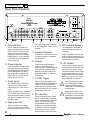
Symphonic
Reference
High Fidelity Control Center
and Preamplifier
SAFETY
Safety
Instructions
1. Read Instructions -– All the safety
and operation instructions should be
read before the SunÞre Component is
operated.
2. Retain Instructions — The safety
and operating instructions should be
kept for future reference.
3. Heed Warnings — All warnings on
the Component and in these operating
instructions should be followed.
4. Follow Instructions — All operating and other instructions should be
followed.
5. Water and Moisture — The
Component should not be used near
water - for example, near a bathtub,
washbowl, kitchen sink, laundry tub, in
a wet basement, or near a swimming
pool, etc.
6. Ventilation — The Component
should be situated so that its location
or position does not interfere with its
proper ventilation. For example, the
Component should not be situated on
a bed, sofa, rug, or similar surface that
may block any ventilation openings; or
placed in a built-in installation such as
a bookcase, cabinet, or closed equipment rack that may impede the ßow of
air through ventilation openings.
8. Power Sources — The Component
should be connected to a power supply only of the type described in these
operation instructions or as marked on
the Component.
9. Power Cord Protection — Powersupply cords should be routed so that
they are not likely to be walked upon
or pinched by items placed upon or
against them, paying particular attention to cords at plugs, convenience
receptacles, and the point where they
exit the Component.
10. Cleaning — The Component should be cleaned only as
recommended in this manual.
11. Non-use Periods—The power
cord of the Component should be unplugged from the outlet when unused
for a long period of time.
12. Object and Liquid Entry — Care
should be taken so that objects do not
fall into and liquids are not spilled into
the inside of the Component.
13. Damage Requiring Service
— The Component should be serviced
only by qualiÞed service personnel
when:
A. The power-supply cord or the plug
has been damaged; or
B. Objects have fallen, or liquid has
spilled into the Component; or
C. The Component has been exposed
to rain; or
D. The Component does not appear to
operate normally
or exhibits a marked change in performance; or
E. The Component has been dropped,
or its cabinet damaged.
14. Servicing — The user should not
attempt to service the Component
beyond those means described in this
operating manual. All other servicing
should be referred to qualiÞed service
personnel.
7. Heat — The Component should be
situated away from heat sources such
as radiators, or other devices which
produce heat.
2
User's Manual
SAFETY
15. To prevent electric shock, do not
use this polarized plug with an extension cord, receptacle or other outlet
unless the blades can be fully inserted
to prevent blade exposure.
Pour préevenir les chocs électriques
ne pas utiliser cette Þche polariseé
avec un prolongateur, un prise de
courant ou une autre sortie de courant, sauf si les lames peuvent être
insérées à fond sans laisser aucune
parIIIe à découvert.
16. Grounding or Polarization —
Precautions should be taken so that
the grounding or polarization means
of the Component is not defeated.
This apparatus does not exceed the
Class A/Class B (whichever is applicable) limits for radio noise emissions
from digital apparatus as set out in the
radio interference regulations of the Canadian Department of Communications.
ATTENTION — Le présent appareil numérique n'émet pas de bruits
radioélectriques dépassant las limites
applicables aux appareils numériques
de class A/de class B (selon le cas)
prescrites dans le règlement sur le
brouillage radioélectrique édicté par
les ministere des communications du
Canada.
WARNING – TO REDUCE THE RISK OF FIRE OR ELECTRIC SHOCK,
DO NOT EXPOSE THIS APPLIANCE TO RAIN OR MOISTURE.
CAUTION: TO PREVENT ELECTRIC SHOCK, MATCH WIDE BLADE
OF PLUG TO WIDE SLOT, FULLY INSERT.
ATTENTION: POUR ÉVITER LES CHOCS ÉLECTRIQUES, INTRODUIRE LA LAME LA PLUS LARGE DE LA FICHE DANS LA BORNE
CORRESPONDANTE DE LA PRISE ET POUSSER JUSQU’AU FOND.
Contents
Safety Instructions................................... 2-3
Chapter 1: Introduction ...............................4
Unpacking and List of Features .................4
Front Panel .................................................5
Rear Panel..................................................6
Installation ..................................................7
Remote Control ..........................................7
Chapter 2: System ConÞgurations .............8
Appendix:
Troubleshooting Guide .............................13
SpeciÞcations ...........................................14
Limited Warranty ......................................15
Service Assistance ...................................15
User's Manual
Please read the Safety Instructions
carefully before connecting and
using your SunÞre PreampliÞer.
Chapter 1 is a general introduction
to the features, details and installation of the preampliÞer.
Chapter 2 shows options for connecting your source equipment and
power ampliÞer.
The Appendix shows some additional information, including a troubleshooting guide, the Warranty, and
service assistance details
To Þnd out more about this and other
SunÞre products, please visit our
website: www.sunÞre.com
3
CHAPTER 1
Introduction
Unpacking
Your SunÞre PreampliÞer should
reach you in perfect condition. If
you do notice any shipping damage,
please contact your SunÞre Dealer
immediately.
Dear Friend,
Thank you for purchasing my
SunÞre Symphonic Reference
PreampliÞer. I hope that you enjoy it
and the music it makes as much as I
have enjoyed creating it for you.
Gently lift out the unit and remove
all the packing material and accessories. It is important to save all the
packing materials and the box in case
your preampliÞer ever needs to be
moved or shipped for repair.
Make sure that you keep your
sales receipt. It is the only way to
establish the duration of your Limited
Warranty and it may come in useful
for insurance purposes.
Please take a moment to Þll
out and mail the SunÞre Customer
Response card. Also read the serial
number located on the rear panel and
record it here:
Serial #:
___________________________
Purchased at:
___________________________
___________________________
___________________________
___________________________
Features
•
•
•
•
•
Pure Stereo PreampliÞer
Five line-level L/R inputs
Full range line-level L/R output
High-pass line-level L/R output
Low noise Phono section with
Moving Magnet and Moving Coil
cartridge selector switch
• Tape Monitor loop
• External Processor loop
• Direct bypass mode
• Treble and Bass Tone controls
• Balance control
• Motorized Volume control with
remote control
• Front panel IR window and LED
• Mute switch
• Mono switch
• 1/4" Headphones jack
• Illuminated input switches
• Indicator LEDs
• Two rear panel IR ports
• 12 VDC trigger for turning on
SunÞre ampliÞers
• IEC removable power cord
• Three unswitched convenience
outlets
• High quality styling and Þnish
• 17 inches wide
• Remote control with matching
styling and Þnish
Date: _______________________
4
User's Manual
CHAPTER 1
Front Panel Features
1
12
2
11
10
1. Power
This turns the preampliÞer on or
off. It is a non-latching momentary
button.
2. Input Selectors
Press one of these illuminated
buttons to select the source you
want to listen to. The selected button will change color.
3. Infrared Remote Control
Window
This window should be clean and
free from obstruction. The LED
will light when a remote control
infrared command is received.
4. Volume
Rotate this control clockwise to
increase the volume. The control
is motorized, and will rotate when
the remote control is used to
adjust the volume. Make sure its
rotation is not restricted.
5. Balance
Rotate this to the left or right until
the soundstage appears equally
balanced.
User's Manual
2
9
8
7
6
6. Tone
These controls apply a cut or
a boost to the Bass and Treble
frequency ranges. In the center
position, there is no effect on the
audio signal. The controls work
independently of each other.
7. Direct
This bypasses the Tone controls
and allows the shortest signal
path through the preampliÞer. Use
this to obtain the cleanest direct
sound through your system.
8. External Processor
Press this to route the preampliÞer signals through an external
processor or graphic equalizer.
9. Tape Monitor
Press this to engage the Tape
Monitor Loop. This is used for
Tape players such as three-head
designs, which allow you to
monitor the actual sound being
recorded.
For example, if you wanted to
record a CD, you would select
the CD input and then press this
Tape button. When you set your
3
4
6
5
Tape player to record, you will
then hear the CD sound as it will
appear on the tape. You will also
hear any adjustments you make
with your Tape player's controls,
such as record level, bias or record balance.
Note: The rear panel Tape output,
and External Processor output,
are not affected by the preampliÞer's Volume, Balance, Mute, Mono
or Tone controls.
10. Mono
Press this to listen to Mono sources. The left and right signal paths
are joined, so Mono sources can
be heard from both speakers.
When engaged, a correctly set up
system should produce a strong
center image directly between the
two speakers.
11. Mute
This turns off the sound. Press it
again to turn the sound back on.
12. Headphones
Use this jack to connect a pair of
your favorite headphones.
5
CHAPTER 1
Rear Panel Features
1
2
3
1. Ground Screw
This is commonly used for the
ground connection wire of a turntable, to prevent any hum in your
speakers. It is tied to the chassis ground, and may be used as
needed. Note: It is not necessary
or desirable to connect this to an
electrical ground.
2. Phono Selector
If you are using a turntable with a
low output Moving Coil cartridge,
set this switch to the MC position.
Use the MM position if it has a
high output Moving Magnet cartridge. This will correctly set the
gain of the Phono circuit.
3. Audio Inputs
Any standard audio component
with a line level output can be
connected to CD, Tuner, Aux1 or
Aux2.
Only a turntable can be connected
to the Phono input. Set the Phono
Selector Switch correctly to match
your type of cartridge before using
the Phono input.
4. Tape In and Out
Tape In connects to the output
(play) of a Tape player, and Tape
Out connects to the input (record).
6
4
5
6
7
The Tape Outputs are unaffected
by the preampliÞer volume or tone
controls.
5. External Processor
If you have an external processor
or graphic equalizer, it should be
connected here.
6. Outputs
These line-level RCA outputs
connect to the inputs of your
power ampliÞer. The Main outputs
cover the main frequency range
between 20 Hz and 20 kHz. The
High-Pass outputs are rolled off
below 80 Hz.
7. 12 VDC Trigger
This 1/8” mini-jack supplies +12
VDC whenever the preampliÞer is
turned on. It can be used to automatically turn on SunÞre ampliÞers for example. Do not exceed a
current draw of 500 mA.
8. IR In and Out
These are used in custom installations to control the preampliÞer
from a remote location. The jacks
accept 1/8” mono mini-plugs
from standard remote control IR
equipment, such as those made
by Xantech and other companies.
Place remote sensors in a preferred location in your main room.
8
8
9
10
9. IEC Linecord Socket
The preampliÞer comes with a
detachable linecord which connects here.
Plug the linecord into an AC wall
socket or power strip which is correctly conÞgured with the voltage
speciÞed for your model.
10. AC Outlets
These three AC outlets allow you
to supply power to the other components in your system. These
unswitched outlets are live whenever the preampliÞer line cord is
plugged into a live wall socket or
power strip. They are live even if
the preampliÞer is turned off.
Take care that the preampliÞer is unplugged or turned
off at the AC wall socket or
supply, before connecting any
linecords here.
Make sure the power consumption of all your components does not exceed 1000
Watts. Do not plug a power
ampliÞer into these outlets.
User's Manual
CHAPTER 1
Installation
Observe the following precautions
when choosing a location for your
preampliÞer:
•
Do not cover any of the ventilation slots.
•
Do not place directly on top of
a power ampliÞer.
•
•
to prevent any hum or interference heard in the speakers.
•
Choose reliable hookup cables.
They should be fully shielded
and as short as possible.
•
Some patch cords can be a
very tight Þt and there is usually a preferred method of getting them off. Some have to be
removed with a twisting action.
Be gentle or you may damage
the jacks of your preampliÞer,
or other components.
Protect it from prolonged
exposure to direct sunlight and
other direct sources of heat,
such as heating vents and
radiators.
Do not expose the unit to rain
or moisture. If ßuid or a foreign object should enter the
unit, immediately turn off the
power and contact your SunÞre
Dealer.
•
Avoid excessive exposure to
extreme cold or dust.
•
Do not place heavy objects on
top of the unit.
AC Power Considerations
Ensure that the unit is plugged
into an outlet capable of supplying
the correct voltage speciÞed for your
model.
Care
If you need to clean the front surface, Þrst turn off the power and then
use a dry cloth, rubbing with the grain.
Be careful not to scratch the Þnish.
•
•
Remote Control
POWER
VOLUME
MUTE
CD
Some audiophile cables should
be hooked up in one direction,
these are usually marked with
arrows.
It is usual for the right channel
patch cord plugs to be red and
the left channel connections to
be white, grey or black.
12 VDC Trigger
The preampliÞer's Trigger terminal supplies 12 VDC whenever the
preampliÞer is turned on. This can be
used to turn on SunÞre power ampliÞers or other equipment with a 12 V
trigger input.
Use all standard safety precautions and make sure all
the equipment is disconnected
before making any connections.
STEREO/
MONO
TUNER
TAPE
AUX1
PHONO
AUX2
TAPE
EXTERNAL SOURCE
MONITOR PROCESSOR DIRECT
Symphonic Reference Preamplifier
Remote Control
Batteries
Use a small Phillips screwdriver
and undo the rear cover of the remote
to change the batteries.
Connection Tips
Functions
Before setting up your new system, please consider the following :
Most functions of the preampliÞer
can be operated by the remote control, except for Tone and Balance.
Always make sure that your
components are all turned
OFF, or unplugged before
making or changing any
connections.
•
Whenever possible, route the
power cords away from the
signal cables or speaker wires
User's Manual
You can connect an external IR
receiver to the preampliÞer's rear IR
port. This will allow you to operate the
preampliÞer from a remote location.
Place the preampliÞer or any
external Infrared receivers in a place
where there is a direct line of sight
from your listening position.
7
CHAPTER 2
System ConÞgurations
The following pages show some typical connections that you might make in your
installation. They show how the inputs and outputs of the preampliÞer are connected to
various audio components.
Input connections
Analog audio signals
From: CD Player audio outputs
To:
PreampliÞer CD L/R audio
inputs
When the CD input is selected
from the front panel or the remote
control, the CD’s audio will play in
your system.
The CD player's AC power cord
can be plugged into the preampliÞer's
convenience outlets if required.
The CD, Tuner, Aux 1, Aux 2 and
Tape inputs will accept audio signals
from any standard line-level source.
Use the left and right analog outputs of your player. The preampliÞer
will not decode digital signals.
8
User's Manual
CHAPTER 2
Turntable Connections
Ground wire
From: Turntable chassis ground
To:
PreampliÞer chassis ground
connector
Phono-level audio signals
From: Turntable L/R audio outputs
To:
PreampliÞer Phono L/R audio
inputs
Only connect a Turntable to the
PHONO input. In most cases, you
should also connect the ground wire
to reduce any hum through your
speakers.
The Phono input is designed
for Moving Magnet (MM)
cartridges and Moving Coil
(MC) cartridges. To avoid overload,
DO NOT connect CD players or other
line-level sources to this input.
User's Manual
Set the Phono selector switch to
either MM or MC depending on the
type of cartridge you have. Do this
before you turn on the preampliÞer.
If you have a low output Moving
Coil cartridge, set the switch to MC. If
you have a high output Moving Magnet cartridge, set it to MM. If you are
not sure which type of cartridge you
have, try MM Þrst, and do a listening
test. If the noise level is high, try setting the switch to MC.
9
CHAPTER 2
Tape Player Connections
Play
Record
Analog audio signals (play)
From: Tape player audio outputs
To:
Preamp Tape L/R audio
inputs
Analog audio signals (record)
From: Preamp Tape L/R audio
outputs
To:
Tape Player L/R audio
input
Connect your Tape player’s analog outputs to the preampliÞer's TAPE
inputs. Connect the Tape player's
inputs to the preampliÞer's TAPE
outputs.
The Tape player can record the
audio from whichever source is
selected. Note that it will record the
original signals, unaffected by the
preampliÞer's Tone, Balance, Volume
or any external processing.
Press the front panel Tape Monitor switch if you have a three-head
player. This will engage the Tape Monitor loop, and allow you to listen to the
exact sounds as they are recorded.
10
User's Manual
CHAPTER 2
External Processor Connections
Analog audio signals
From: External Processor's audio
outputs
To:
Preamp External Processor
L/R audio inputs
Analog audio signals
From: Preamp's External
Processor L/R audio
outputs
To:
External Processor's L/R
audio input
The preampliÞer audio signals
can be passed through an external
processor or graphic equalizer.
The signals going into your
external processor are not affected by
the preampliÞer's volume, balance or
Tone controls.
Take care to exercise moderation
with your external processor's controls. Too much gain may overload the
preampliÞer circuits, causing distortion.
User's Manual
11
CHAPTER 2
Output Connections
Line-level audio signals
From: PreampliÞer main outputs
To:
AmpliÞer line-level inputs
12 VDC Trigger voltage
From: PreampliÞer 12 VDC trigger outputs
To:
AmpliÞer 12 VDC trigger inputs
The preampliÞer's line-level Main
audio outputs can be connected to
a power ampliÞer as shown. This
example shows the matching SunÞre
Symphonic Reference power ampliÞer. The 12 VDC connection can be
used to turn the ampliÞer on when the
preamp turns on.
12
NOTE: As an alternative, you
could connect the preampliÞer's HighPass outputs to the ampliÞer, and connect the preampliÞer's Main outputs
to a Powered Subwoofer. In this way,
the main speakers can play the range
above 80 Hz, and the subwoofer can
play the low range. Set your subwoofer's crossover point at 80 Hz. This
system is beneÞcial if you have small
mini monitor type speakers, with weak
bass response.
User's Manual
APPENDIX
Troubleshooting Guide
Make sure that they are
disconnected where they
Þrst enter the room, so they
are making no connection to
the preampliÞer or the TV, or
any other component. If the
hum is caused by the cable
TV line, then you will need a
“ground loop isolator.” This is
an inexpensive device Þtted in
line with the coaxial cable feed.
Contact your cable company or
your SunÞre Dealer for assistance.
The SunÞre PreampliÞer is expertly designed and built to provide
years of trouble-free performance.
Most problems that occur can usually
be solved by checking your setup or
making sure that the audio and video
components connected to the processor are on and fully operational.
The following information will help
you deal with common setup problems
you may experience during normal
use of your unit. If the problems still
persist, please contact your SunÞre
Dealer for assistance.
No sound from one or
more speakers
•
Speaker cables may have
come undone. Turn off your
system and check the cables,
and tighten the ampliÞer and
speaker binding posts.
•
Broken audio cable.
•
The balance level is low for the
channel concerned.
•
The Mute switch is on.
A Hum is heard in your
speakers
This problem is more than likely
caused by a “ground loop” in your
system, rather than a fault in the preampliÞer. Follow these steps to isolate
the main cause of the hum, there may
even be more than one.
•
Remember to turn off all
components in your system, including the preampliÞer, before
disconnecting or connecting
any cables.
•
Disconnect the following items
in order, and check each time if
the hum has gone away:
•
Disconnect all cables which
come from outside the room,
such as cable TV, satellite
TV, or roof top antennas.
User's Manual
•
Disconnect all connections
from the preampliÞer to your
TV, VCR or DVD.
•
Disconnect any component
which has a grounded power
cord.
•
If the hum persists, disconnect
all the source components one
at a time from the back of the
preampliÞer, until you identify
the problem.
•
Ground loop isolators are available for audio lines and video.
You can ask your SunÞre
Dealer for assistance.
•
•
Try moving the speaker cables
away from any power cords.
Try just one speaker, connecting it to different channels and
see if an ampliÞer channel is
bad.
If you are still having a problem, remember that SunÞre’s
dealers and technical support
staff will assist you.
Other causes of noise
•
Speaker noise may also be
caused by interference or
noise on your AC line. Make
sure there are no large appliances sharing the line, or
halogen lamps or light-dimming
Triac devices.
•
Try connecting your system to
another AC socket on a separate line.
•
Keep power cords away from
audio cables.
•
Do not place the preampliÞer directly on top of a power
ampliÞer.
•
If the hum is heard from
within the preampliÞer and
not through the speakers, this
may also be caused by interference on the AC or DC lines.
The power transformers may
turn this interference into an
audible noise. Internal hum can
be made worse by a shelf or
cabinet resonating, so try moving the preampliÞer to another
shelf.
•
Try moving your components
further away from the TV, especially if you ever notice the
screen has changed color in
the area closest to the component.
•
If you have very high efÞciency
speakers, these may show up
noise which other speakers
may not.
Remote will not work
•
Make sure the batteries are not
dead.
•
Make sure that the preampliÞer
front panel receiver window is
not obstructed, or tilted away
from the listening position.
PreampliÞer does not respond to any controls
•
Unplug AC power momentarily,
and press the Power button to
turn back on
13
APPENDIX
SpeciÞcations
Line input to Main output
Line Gain:
17.7 dB +/- 0.5 dB
Max level out: 7.2 Vrms at 1 KHz
Max level in: 10 Vrms at 1 KHz
Separation:
Trigger Outputs
12 VDC Trigger, current less than
500 mA total
Infrared ports
> 70 dB at 1 KHz
Optically Isolated
> 50 dB at 10 KHz
Standard 1/8” mini jacks
Frequency Response:
20-20 KHz +/- 0.2 dB
Standard 12 V signal level
THD:(2 V out) <0.005% 20-20 KHz
Dimensions
S/N (2 V out, A-weighted):
>100 dB
Net Weight
Crosstalk between inputs:
> 100 dB
(2 V in, 1 KHz)
Mute:
> 50 dB
Phono section
17” W x 5.75” H x 16.5” D
16 lbs
AC line operation
Meets the speciÞcations above from
90-130 VAC 50-60 Hz
Phono Gain:
MM = 41 dB +/- 1 dB
MC = 65 dB +/- 1 dB
Phono Noise:
MM > 82 dB
MC > 71 dB
Phono Input Impedance
MM 47K ohms
MC 240 ohms
Tone Controls
Tone Response 100 Hz, 10 KHz
Bass Boost
+13.5 dB +/- 1 dB
Bass Cut
-5.2 dB +/- 1 dB
Treble Boost +4.5 dB +/- 1 dB
Treble Cut
-3.5 dB +/- 1 dB
High pass section
Freq Response: -3 dB at 80 Hz,
12 dB / octave
© 2002 SunÞre Corporation.
All rights reserved. SunÞre Corporation reserves the right to improve
its products at any time. Therefore,
speciÞcations are subject to change
without notice.
Manual part number:
913-046-00 Rev A
14
User's Manual
APPENDIX
Limited Warranty
SunÞre Corporation is proud of its
products which have been built with
care using advanced technology and
premium component parts. Your unit
has been crafted to perform properly
for many years. SunÞre Corporation
offers the following Warranty to you,
the owner of a new SunÞre product:
The SunÞre Corporation Warranty
for the Symphonic Reference PreampliÞer is in effect for TWO years from
the date of original retail purchase.
The SunÞre Corporation Warranty
covers defects in materials and workmanship. The following, however, are
excluded:
a) Damage caused during shipment.
b) Damage caused by accident,
misuse, abuse of operation
contrary to the instructions
speciÞed in the SunÞre Corporation user’s manual.
c) Units where the serial number
has been defaced, modiÞed or
removed.
d) Damage resulting from modiÞcation or attempted repair by
any person not authorized in
writing by SunÞre Corporation.
e) Units purchased from unauthorized dealers.
The SunÞre Corporation Warranty extends to the original owner
or subsequent owner(s) during the
two year warranty period so long as
the original dated purchase receipt is
presented whenever warranty service
is required.
Service Assistance
SunÞre Corporation’s liability is
limited to the repair or replacement,
at our option, of any defective product and shall not in any event include
property or any other incidental or
consequential damages which may
result from the failure of this product.
Some states do not allow limitations
on how long an implied warranty lasts
and/or do not allow the exclusion or
limitation of incidental or consequential
damages, so the above limitations or
exclusions may not apply to you.
This Warranty gives you speciÞc
legal rights, and you may also have
other rights which vary from state to
state. We suggest that you attach your
purchase receipt to this Warranty and
keep these in a safe place. Thank you
for your choice of a SunÞre Corporation product.
We suggest that you read the Limited
Warranty completely to fully understand your Warranty/Service coverage.
If your SunÞre Corporation product ever requires service, write to us
or call:
SunÞre Corporation
Technical Services Department
P.O. Box 1589
Snohomish, WA 98291
Tel (425) 335-4748
Fax (425) 335-4746
You will be directed to an authorized SunÞre Corporation Service
Station or receive instructions to ship
the unit to the factory. Please save the
original shipping carton and packing
materials in case shipping is required.
Please do not ship Parcel Post.
NOTE: Before sending in your unit for
repair, you must call SunÞre for return
authorization.
Include a complete description of the
problem, indicating how you have it
connected, the associated equipment
in your system and a copy of your
purchase receipt. Initial shipping costs
are not paid by SunÞre Corporation;
return ground shipping costs will be
prepaid if repairs were covered by the
scope of this Warranty.
All implied warranties, including
warranties or merchantability and
Þtness for particular purposes, are limited in duration to the two year length
of this Warranty, unless otherwise
provided by state law.
User's Manual
15
Symphonic Reference
High Fidelity Control Center
and Preamplifier
Manual part number : 913-046-00 Rev A