1
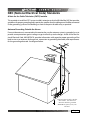
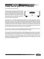
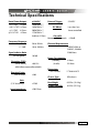
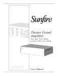
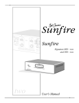
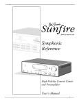
USER’S GUIDE
TABLE OF CONTENTS
Safety Precautions ................................................... 4
NEC (National Electrical Code) Standards..............................6
A Note for the Cable Television (CATV) Installer ................................................... 6
Antenna Grounding Outside the House ................................................................. 6
Thank You for your IPS-1 Purchase......................... 7
Unpacking the IPS-1.................................................. 8
Recording the Serial Number...................................................8
Emotiva IPS-1 Integrated Power Amplifier.............. 9
Integrated Professional Power Amplifier Features ...............9
IPS-1 Front Panel Features..................................... 10
Power Button .......................................................................................................... 10
Panel Dim Selector Button..................................................................................... 10
Amplifier Channel Display ..................................................................................... 10
IPS-1 Rear Panel Layout ......................................... 11
Channel ID Area ...................................................................................................... 11
RCA Inputs .............................................................................................................. 11
Speaker Output Terminals ..................................................................................... 11
Turn On Selector Switch ........................................................................................ 12
External Trigger Connection.................................................................................. 12
Fuse ......................................................................................................................... 12
Power Switch .......................................................................................................... 12
IEC Line Cord Socket ............................................................................................. 12
Installation and Connections ................................. 13
AC Power Considerations ......................................................13
Input Connection Considerations..........................................13
Output Connection Considerations.......................................14
Automatic Operation of the Cooling Fan(s)..........................14
Connection Tips for Superior Sound.....................................14
Connection Diagrams .............................................................15
Input Connections .................................................................................................. 15
12V Trigger Connections ....................................................................................... 16
Speaker Output Connections ................................................................................ 16
Series and Parallel Speaker Connections.............................17
Series ....................................................................................................................... 17
Parallel ..................................................................................................................... 18
Technical Note about Multiple Speaker Connections ......................................... 18
Flexible IPS-1 Applications.....................................................19
5.1 and Zone 2 Amplification ................................................................................. 19
Speaker Placement Tips ......................................... 20
Tips Before You Begin ............................................................20
The Front Speakers ................................................................................................ 21
The Center Speaker ................................................................................................ 21
Side-Axis Speakers ................................................................................................ 22
The Surround Speakers ......................................................................................... 22
Surround Back Speakers ....................................................................................... 23
Subwoofer Location ............................................................................................... 23
Troubleshooting Guide ........................................... 25
No Sound (from one or more speakers connected to the IPS-1) ....................... 25
The amplifier shuts down often or the line fuse blows often ............................. 25
Poor Bass Performance From Full Range Speakers connected to the IPS-1... 26
Turn-on and turn-off thumps ................................................................................. 26
“Hum” Noises in the Speakers.............................................................................. 26
Other Probable Causes of Noise........................................................................... 27
One or more RED lights on the Front Panel are On ............................................ 27
Technical Specifications......................................... 28
Limited Warranty ..................................................... 29
Service Assistance for the IPS-1........................................................................... 29
Emotiva Disclosure ................................................................................................ 30
Safety Precautions
Read this User’s Guide thoroughly before attempting to install and configure the Emotiva IPS-1 Modular Power Amplifier. All the safety and operation instructions should be read before any operation of
the component(s) begin. After successful installation and configuration of the Emotiva IPS-1 Modular
Power Amplifier, be sure to retain this manual in a safe place for any future reference needs.
All warnings on the Emotiva IPS-1 Amplifier and in these operating instructions should be followed.
Safety is a key component to a long lasting and trouble free installation. The vast majority of the
subsequent safety precautions involve simple common sense. If you are not comfortable with the
installation of audio/video entertainment equipment, it will be to your benefit to seek the services
of a qualified installation professional.
• The Emotiva IPS-1 Amplifier should NEVER be used near water such as a bathtub, washbowl, kitchen
sink, laundry tub, in a wet basement, or near a swimming pool, etc.
• The Emotiva IPS-1 Amplifier should be situated so that its location or installation position does not
interfere with proper ventilation.
• The Emotiva IPS-1 Amplifier should not be situated on a bed, sofa, rug, or similar surface that may block
any ventilation openings; or placed in a built-in installation such as a bookcase, cabinet, or closed
equipment rack that may impede the flow of air through ventilation openings. If installed in a closed
equipment rack for custom installations, be sure to add forced air ventilation so that it has adequate
air circulation.
• The Emotiva IPS-1 Amplifier should be situated away from heat sources such as radiators, or any other
devices which produce heat.
• The Emotiva IPS-1 Amplifier should be connected to a power supply only of the type described in this
User’s Guide and what is labeled on the IPS-1 component. Power supply cords should be routed so that
they are not in high foot traffic areas or pinched by items placed upon or against them, paying particular
attention to cords at the wall plugs, convenience receptacles, and the point where they connect into
the IPS-1 Amplifier. The power cord of the IPS-1 Amplifier should be unplugged from the outlet when
unused for a long period of time.
When it’s time for cleaning the Emotiva IPS-1 Amplifier, it should be cleaned only as recommended
in this User’s Guide. Never spray liquids directly into the component’s vent openings. Care should
be taken so that small objects do not fall into the inside of the IPS-1 Amplifier.
The following situations require your Emotiva IPS-1 Amplifier is serviced only by qualified service
personnel:
1. The power-supply cord or the plug has been damaged; or
2. Objects have fallen, or liquid has spilled into the component; or
3. The IPS-1 has been exposed to rain; or
4. The IPS-1 does not appear to operate normally or exhibits a marked change in performance; or
5. The IPS-1 has been dropped, or its enclosure or chassis is damaged.
Page 4
The user should not attempt to service the IPS-1 Integrated Power Amplifier beyond the means described in this User’s Guide. All other servicing should be referred to qualified service personnel.
To prevent electric shock, do not use this polarized plug with an extension cord, receptacle or
other outlet unless the blades can be fully inserted to prevent blade exposure.
Pour preevenir les chocs electriques ne pas utiliser cette fiche polarises avec un prolongateur, un prise de
courant ou une autre sortie de courant, sauf si les lames peuvent titre inserees a fond sans laisser aucune
parIIIe a decouvert.
Grounding or Polarization — Precautions should be taken so that the grounding or polarization
means of the component is not defeated.
This apparatus does not exceed the Class A/Class B (whichever is applicable) limits for radio noise
emissions from digital apparatus as set out in the radio interference regulations of the Canadian
Department of Communications.
ATTENTION — Le present appareil numerique n’emet pas de bruits radioelectriques depassant las limites
applicables aux appareils numeriques de class A/de class B (selon le cas) prescrites dans le reglement sur
le brouillage radioelectrique edicts par les ministere des communications du Canada.
For questions regarding service, please contact:
Emotiva
106 Mission Court, Suite 101
Franklin, TN 37067
Tel - (615) 771-1224
Fax - (615) 771-1128
(877) EMO-TECH
www.emotiva.com
WARNING – TO REDUCE THE RISK OF FIRE OR ELECTRIC SHOCK, DO
NOT EXPOSE THIS APPLIANCE TO RAIN OR MOISTURE.
CAUTION: TO PREVENT ELECTRIC SHOCK, MATCH WIDE BLADE OF PLUG
TO WIDE SLOT, FULLY INSERT.
ATTENTION: POUR EVITER LES CHOCS ELECTRIQUES, INTRODUIRE LA
LAME LA PLUS LARGE DE LA FICHE DANS LA BORNE CORRESPONDANTE
DE LA PRISE ET POUSSER JUSQU’AU FOND.
Page 5
NEC (National Electrical Code) Standards
A Note for the Cable Television (CATV) Installer
This reminder is to call the CATV system installer’s attention to Article 820-40 of the NEC that provides
guidelines for proper grounding and in particular, specifies that the cable ground shall be connected
to the grounding system of the building as close to the point of cable entry as practical.
Antenna Grounding Outside the House
If an outside antenna is connected to the receiver, be sure the antenna system is grounded so as to
provide some protection against voltage surges and built-up static charges. Article 810 of the National Electrical Code, ANSI/NFPA 70, provides information with regard to proper grounding of the
lead-in wire to an antenna-discharge unit, connection to grounding electrodes, and requirements
for the grounding electrode. See diagram below.
Cable TV Coaxial Cable, Satellite
Dish Cables, and Television
Antennas should be grounded
BEFORE the point of entry into
the house.
Page 6
Thank You for your IPS-1 Purchase
Dear Home Entertainment Enthusiast,
Thank you for purchasing the Emotiva IPS-1 Integrated Power Amplifier. We sincerely believe that it offers
you outstanding performance and value. Emotiva
products are engineered and produced with the
highest quality materials and incorporate the latest
technology. We think you will find the Emotiva IPS-1
meets or exceeds your expectations.
The Emotiva IPS-1 is a flexible, high performance amplifier. It has been designed for maximum
performance, ease of use, and installation flexibility. By employing cutting edge technology, the
Emotiva IPS-1 easily delivers music signals to your speakers at powerful levels, while at the same time
remaining as efficient as possible, regardless of volume levels. This allows you to fully enjoy audio
and video sources without concern for dynamic headroom during complex musical passages and
high level effects. What’s more, the Emotiva IPS-1 does it all with exceptionally refined cosmetics
and a sound quality that will satisfy even the most discriminating tastes.
The Emotiva IPS-1 features an array of leading edge technologies and all the features necessary to
perform the functions expected of a high end Integrated Power Amplifier.
The Emotiva IPS-1 Integrated Power Amplifier is a rock solid component that allows you to control
and manage all of your system’s speakers with 7 individual amplifier channels (each configured as a
separate circuit board in a single amplifier chassis). This makes installation of your home entertainment system much easier than connecting multiple mono or two channel amplifiers. At Emotiva, we
remember that creating home audio/video products means that they should be easy to use while
delivering unparalleled performance.
Page 7
Unpacking the IPS-1
The Emotiva IPS-1 Modular Power Amplifier should reach you in flawless condition. If you notice any
shipping damage or other issues upon unpacking the unit, please contact your Emotiva Retailer
immediately.
Gently lift out the unit and remove all the packing material and accessories. It is important to save
all the packing materials and the box in case your Emotiva IPS-1 ever needs to be moved or shipped
back to the factory for service.
Make sure that you keep your sales receipt. It is the only way for Emotiva to establish the duration
of your Limited Warranty and it may come in useful for insurance purposes. Please take a moment
to fill out and mail the Emotiva Customer Response card.
Recording the Serial Number
Please read the serial number located on the rear panel and record it below. Also record the place
where you purchased this product and the date of purchase.
Model Number
IPS-1
Serial Number
Place of Purchase
Date of Purchase
Page 8
Emotiva IPS-1 Integrated Power Amplifier
Integrated-Modular Power Amplifier Features
• A true audiophile quality power amplifier
• 150 Watts x 7 into 8 Ohms
• 200 Watts x 7 into 4 Ohms
• Completely stable into 2 ohm loads
• Each channel features independent 250VA, low noise toroid power transformers w/ high speed rectifiers
and low ESR 105°C filter capacitors
• High efficiency Class H power amplifier design, minimizes power losses and allows cool and efficient
operation
• Complementary, discrete power amplifier design incorporating high current, high speed, Toshiba power
devices
• RCA inputs
• 5 Way Binding Post speaker outputs
• Silent turn on/off - No audible transients
• THD less than .015%, 20Hz-20kHz with 80kHz measurement bandwidth
• DC offset, less than 1mv, servo controlled.
• Crosstalk between ANY two channels – greater than 120dB
• All aluminum capacitors are premium quality, low ESR, 105°C rated for high reliability and performance
• Doubled sided, plate through, glass epoxy, FR4 PCB’s used throughout with 2 ounce poured copper on
all power sections and ground planes
• Individual channel status indicators for standby, operate, and fault behind tinted acrylic panel
• Fully protected from all fault conditions
• Soft start circuitry
• Signal sensing auto turn-on or remote 12 VDC trigger.
• Soft touch power switch
• 3RU chassis w/ solid milled aluminum faceplate
• IEC power inlet, 120 VAC-60Hz
Page 9
IPS-1 Front Panel Features
3
2
1
1 Power Button
This turns the main power to the IPS-1 on
or off. It is a main power button, but it is
not required to turn this on and off each
time the IPS-1 is used. When enabled, the
AUTO ON/OFF MODE will automatically
switch the amplifier on when an audio
signal comes from a source or control
unit (such as a preamplifier). The TRIGGER
MODE will turn the amplifier on when an
external source (such as a preamplifier)
provides a 5-24 VDC input on the trigger
terminals.
2 Panel Dim Selector Button
This button selects the overall brightness
of the lighting on the front panel of the
IPS-1. The button has four steps, each consecutively after the other. The four levels of
brightness are:
• High
• Medium
• Low
• OFF
Pressing the PANEL DIM button repeatedly
will scroll through each level of brightness.
3 Amplifier Channel Display
This multi-color LED display behind a tinted
acrylic panel shows states of any of the
seven power modules on the IPS-1.
BLUE LIGHT: Power Module is on and
ready.
AMBER LIGHT (middle row): Power module is powered on but is in a standby situation waiting for audio signal or external
trigger.
RED LIGHT: This indicates a fault condition.
A fault condition is one or more of the following:
• Excessive Operating Temp
• Excessive Current (Short Circuit)
• DC on the Outputs
See the “Troubleshooting Section” for more
details on the display.
Note - When there is NO LIGHT - The power
module’s fuse is blown.
Page 10
IPS-1 Rear Panel Layout
4
5
1
2
6
7
3
8
1 RCA Inputs
The IPS-1 has one RCA input available for
each amplifier channel module. Connect
this to the corresponding RCA jack on your
preamplifier to provide signal to the amplifier channel. See page 15 for a connection
diagram.
2 Channel ID Area
The IPS-1 amplifier comes with self adhesive labels to use as channel identification.
Simply apply the label that corresponds to
the appropriate channel to this area and
it will make I/O connections or future
troubleshooting much easier.
3 Speaker Output Terminals
The speaker output terminals for each amplifier channel are located just below the RCA input
jack and channel ID label area. The top post of each binding post pair is the positive output,
and connects to the positive (red) post of your speaker. The bottom post of each pair is the
negative, and connects to the negative (black) post of your speaker. The posts can accept bare
wire, spade terminals, and dual or single banana connectors.
Spade connections or banana plugs ensure a simple, solid fit in the terminal whereas bare wire
may be awkward when the terminal is screwed down to compress the wire into place. Keep in
mind that if you use “dual banana” plugs and “stack” them, you will be creating a parallel connection. For more details on series and parallel connections, see pages 17-18.
Page 11
4 Turn On Selector Switch
Turn On Selector Switch
This switch allows you to select how the
amplifier will turn on and off.
In the ON (Up) position, the switch on the
front of the amplifier is the method you
will use to power up and power down the
amplifier. Please note that in this configuration, you must manually power up and
power down the amplifier each time you
use it or it will have unnecessary standby
current draw.
In the SIGNAL (Middle) position, the amplifier automatically turns on whenever it
senses an audio signal on any one of the
seven amplifier channels. The circuit stays
active for a 30 minutes after the absence of
any audio signal to account for quiet passages of music or dialogue and muting the
audio (for a phone call for example).
In the TRIGGER (Down) position, the amplifier’s ON and OFF functions are controlled
by a trigger from a source or preamplifier
device. The trigger accepts 12 VDC and will
turn the amplifier on whenever a trigger is
present (See #5). When there is no trigger,
the amplifier goes into standby mode. This
is the preferred method for activating the
IPS-1.
5 External Trigger Connection
This external trigger connection allows
the amplifier to be turned ON and OFF by
a control device such as a source unit or
preamplifier. It can also be used with most
home automation controllers. The trigger
requires a 12 VDC trigger. This is the preferred method of activating the IPS-1. See
page 16 for connection details.
External Trigger
Connection
6 Fuse
This fuse is for the power supply of the IPS1 chassis. It is a TL15AL type rated a 15A
Slo-Blo, 250 V. If the fuse ever fails, be sure
to replace it with the same type and rated
fuse.
7 Power Switch
This switch should remain in the ON position for normal operation of the IPS-1
amplifier. When you are away from your
entertainment system for long periods,
this provides a convenient way to switch
the unit off without having to unplug power
cords.
8 IEC Line Cord Socket
The IPS-1 comes with a detachable line cord
which connects here. Plug the line cord into
an AC wall socket which is correctly configured with the voltage and current supply
specified for the IPS-1. Do not plug this line
cord into a power strip, it must plug directly
into a wall socket. For more details on AC
power considerations, see page 13.
Page 12
Installation and Connections
Observe the following precautions when choosing a location for your Emotiva IPS-1:
1) Protect it from prolonged exposure to direct sunlight and other direct sources of heat, such as heating
vents and radiators.
2) Do not expose the unit to rain or moisture. If fluid or a foreign object should enter the unit, immediately
turn off the power and contact your Emotiva Dealer.
3) Avoid excessive exposure to extreme cold or dust.
4) Do not place heavy objects on top of the unit.
5) If you need to clean the front surface, first turn off the power and then use a soft dry cloth, rubbing with
the grain. Be careful not to scratch the display window.
AC Power Considerations
Ensure that the unit is plugged into an outlet capable of supplying the correct voltage and current
specified for your model. Remember to account for the electrical power that other components will
require if they share a common wall socket or electrical circuit. The majority of household electrical
sockets in places other than the kitchen and garage are 15 amperes maximum. Most DVD players
and other source components are fairly low current items. When all seven amplifier channels are
connected to speakers, the Emotiva IPS-1 requires a minimum of 15 amperes @ 120 volts or 8 amperes @ 230 volts. It should be sufficient to allow the other devices such as preamplifiers and A/V
source units to share a wall socket, but power amplifiers such as the IPS-1 and a video display (big
screen TV or video projector) should be provided a SEPARATE electrical connection on a SEPARATE
circuit. As the IPS-1 has a minimum requirement that consumes one entire circuit, please use a second (separate) electrical connection for other devices. DO NOT plug the IPS-1 into a power strip or
extension cord unless the device is specifically designed and rated for high current use.
Refer to your preamplifier, A/V source component(s), and video display owner’s manuals to learn
the power requirements so you can safely plan your electrical power requirements for your home
entertainment system.
Input Connection Considerations
Whenever possible, keep preamp level audio cables away from electrical power cords by at least a
few inches. It’s more important with amplifiers as the AC power cords are carrying much more current than other source and preamplifier components, which means there is a larger degree of noise
or “hum” potential with the amplifier power cord proximity.
Page 13
Output Connection Considerations
The output connectors provided on each channel of the IPS-1 are standard “binding post” speaker
connectors with industry standard spacing. These are sometimes called 5-way binding posts because
of the many ways in which the speaker wire can connect into the posts. The posts can accept bare
wire, spade terminals, and dual or single banana connectors. Spade connections or banana plugs
ensure a simple, solid fit in the terminal whereas bare wire may be awkward when the terminal is
screwed down to compress the wire into place. Keep in mind that if you use “dual banana” plugs
and “stack” them, you will be creating a parallel connection. For more details on series and parallel
connections, see pages 17-18.
It is important to observe polarity so that the speaker wire connects to the red and black terminals
on the amplifier and the corresponding terminals at the speaker. Also make sure that the positive
speaker wires do not touch the negative speaker wires, or any chassis metal. This will cause a short
circuit and activate the protection circuitry.
Ensure Adequate Ventilation
The Emotiva IPS-1 has the power amplifier components arragned in such a fashion to allow heat to
rise off of the components and out through the top vents of the chassis. Bottom vents allow fresh
air in to create a circulation of the heated air. While the surface area of the heatsink on each amplifier circuit board is very generous, we advise all installations to leave 2-3 inches above the top of
the IPS-1 chassis so that adequate ventilation is supported. Furthermore, it is not advised to place
another amplifier below the unit as that heat will have to also pass up through the IPS-1.
Connection Tips for Superior Sound
Before setting up your new system, please consider the following:
• Always make sure the IPS-1 is turned off before making or changing ANY connections.
• Whenever possible, route the power cords away from the signal cables or speaker wires to prevent
any hum or interference heard in the speakers.
• Many RCA type patch cords can be a very tight fit and there is usually a preferred method of getting them off. Some have to be removed with a twisting action. Be gentle or you may damage the
jacks of your IPS-1, the cables themselves, or other components.
• Many audiophile signal cables are intended to be hooked up in one direction. If this is the case the
cables will be marked with arrows the direction of signal flow.
• It is usual for the right channel RCA patch cord plugs to be red and the left channel connections
to be white, grey, or black (depending on the cable brand). RCA connectors that are gold will be
designated with a colored band to designate the channel.
Page 14
Connection Diagrams
Input Connections
If your preamplifier has RCA outputs, it can easily be connected to the amplifier inputs as shown.
The amplifier will boost the preamplifier’s output, up to a level suitable for driving speakers.
Make sure that the positive speaker wires do not touch the negative speaker wires, or any chassis
metal. This will cause a short circuit and may activate the protection circuitry. The 12 VDC trigger
connection shown can be used to turn the amplifier on when the preamplifier turns on. This is the
preferred method of activating the IPS-1. Alternatively, you could use the amplifier’s SIGNAL switch
position. The amplifier will then automatically turn on when a preamp audio signal is received.
Page 15
12V Trigger Connections
The 12 VDC trigger connection shown can be used to
turn the amplifier on when the preamplifier turns on.
This trigger will actually trigger with any switched DC
Voltage from 5-24 VDC, however the majority of home
theater components use a standard 12 VDC trigger
connection for this function. This is the preferred connection as it has the greatest degree of reliability.
Never switch anything that plugs directly into the
wall with this trigger connection. This action will
damage the unit and VOID THE WARRANTY.
If unable to use the trigger connection to activate
the IPS-1, you could alternatively use the amplifier’s
SIGNAL switch position. The amplifier will then automatically turn on when a preamp audio signal is
received.
The trigger connection plug and turn-on selector
switch are located on the top right corner of the back
of the IPS-1 chassis
Speaker Output Connections
The speaker output terminals for each amplifier
channel are located just below the RCA input jack
and channel ID area. The top post of each binding
post pair is the positive output, and connects to
the positive (red) post of your speaker. The bottom
post of each pair is the negative, and connects to
the negative (black) post of your speaker.
Regardless of the configuration used for the IPS1 amplifier channels, proper connection of each
speaker is essential. The 5-way binding posts can
accept bare wire, spade terminals, and dual or
single banana connectors. Spade connections
or banana plugs ensure a simple, solid fit in the
terminal whereas bare wire may be awkward
when the terminal is screwed down to compress
the wire into place. Keep in mind that if you use
“dual banana” plugs and “stack” them, you will be
creating a parallel connection.
Spade connections ensure a tidy and safe connection
to each speaker output binding post.
Page 16
Series and Parallel Speaker Connections
Whenever connecting more than one speaker per channel to an amplifier (regardless of the brand),
you must consider the way in which the amplifier will be impacted by adding the additional
speaker(s). Additionally, speakers with dual voice coils also apply to this consideration. Two voice
coils in a single speaker also cause different reactions from an amplifier depending on the way in
which they connect to the amplifier.
The connection of more than one speaker per channel will tend to degrade the speaker’s frequency
response and may make the amplifier run hot. For the best sonic results, use one speaker per amplifier channel. If you must connect more than one speaker per channel, there are two methods in
which to do so: Series or Parallel.
Series
A series connection is established when voice coils are connected in a string – end to end – so
there’s only one way for audio signals to flow “in” and only one way for audio signals to flow “out”.
For example, if you were to series-connect two speakers
to the front right channel of the amplifier:
• The positive output terminal of the right channel connects
to the positive input post of the first speaker.
• The negative input post of the first speaker connects to the
positive input post of the second speaker.
• The negative input post of the second speaker connects to
the negative output terminal of the right channel.
The total impedance of speakers in series is found by
adding their impedances together. For example, two
four ohm speakers in series is an eight ohm load. Series
connections are easier on the amplifier than parallel connections as the total impedance is higher than driving a
single speaker.
An example of a SERIES connection
between two speakers
Page 17
Parallel
A parallel circuit is established when voice coils are connected in a way that there are multiple
paths for audio signals to flow “in” and multiple paths for audio signals to flow “out”. When speakers
are connected in parallel, the total resistance at the amplifier is proportionally divided based on
the value of each individual voice coil resistance. The term “divided” simply means all of the values
together in parallel are a SMALLER value than each all by itself. For example, if you were to parallel
connect two speakers to the front right channel of the amplifier:
• The positive output terminal of the right channel connects to
the positive input post of the first speaker and to the positive
post of the second speaker.
• The negative output terminal of the right channel connects to
the negative input post of the first speaker and to the negative
post of the second speaker.
The total impedance of equal speakers in parallel is found
by dividing the impedance of one speaker by the number of
speakers. For example, two eight ohm speakers in parallel is
a four ohm load (eight ohms divided by two), four eight ohm
speakers in parallel is a two ohm load (eight ohms divided
by four).
Parallel connections are harder on the amplifier than series
connections, as the total impedance is lower compared to
driving a single speaker, and the amplifier must produce
more current to drive them.
An example of a PARALLEL
connection between two speakers
Ideally, the total average impedance should be no less than 4 ohms per channel. You must make
sure that the lower impedance does not cause the amplifier to overheat, shut down, blow the line
fuse, or pop your circuit breaker. If this happens, you should reduce the number of speakers wired
in parallel, rewire them in series, or use more than one power amplifier.
Technical Note about Multiple Speaker Connections
Although there are two possible connection types discussed in this manual, it is imperative that
with either connection type that you use loudspeakers of the same type and nominal impedance for
these connections. In doing so, you have the most predictable outcome for your installation. When
speakers of different nominal impedances and/or different bandwidths are used, there are many
other acoustic problems that come into play in addition to complex impedance at the amplifier’s
speaker output terminals. If you must use multiple speakers on any individual amplifier channel,
please use speakers as close to identical as possible.
Page 18
Flexible IPS-1 Applications
5.1 and Zone 2 Amplification
This example shows the IPS-1 with the companion MMC-1 preamplifier/processor used in a 5.1 and
Zone 2 arrangement. If you are not intending to use side axis speakers in a 7.1 system, the IPS-1
amplifier is ideally suited for this configuration.
As an example, a CD Player, iPod with dock, and DVD player are shown as source inputs to the preamp.
Obviously, the actual components you might connect depend on your own system.
To HDMI Input
on the TV
Page 19
Speaker Placement Tips
Tips Before You Begin
Read this section thoroughly. There are a number of ways in which it may seem aesthetically pleasing
to place speakers in a room that will ultimately result in a sound quality compromise. The placement
of speakers is equally as important as the room itself. While there may be very little you can do about
the room where your home theater is installed, you can choose placement of speakers within that
room to maximize the sound quality of the system. Ultimately, this will give a much better result
when you are enjoying your home theater and your new Emotiva IPS-1.
Overall, the best placement for front speakers is where the sound is directed at ear level. This means
that the speakers themselves can be in positions lower (like small floor standing speakers) or higher
(like in-wall or in-ceiling speakers) as long as the sound is “pointed” toward the listeners and preferably around ear level. This is not necessarily the case with the rear speakers or the side axis speakers.
Read each of the sections carefully for the most appropriate positioning. A subwoofer is also a little
challenging to install depending on the room. In multiple subwoofer installations, the positioning
of the woofers to the listener as well as to each other is critical because there can be problems with
cancellation if optimum placement is not observed.
Page 20
The Front Speakers
You should closely follow the placement recommendations
of your speaker manufacturer, with the addition of the following points:
• The left and right front speakers should be positioned so that
your TV is exactly centered between them. This will help focus
your attention towards the screen.
• For the best overall imaging, the left speaker should be set
exactly the same distance and angle away from your listening
position as the right speaker. It is recommended that you use
Place LEFT, CENTER, and RIGHT main
a tape measure to set them up to be the same distance away,
speakers at equal distances from the
within about half an inch tolerance.
listening position.
If you have a smaller TV, the speakers should be no more than two feet away from the sides of the
TV. If possible, have the center, left and right speakers at the same height (within two feet). This will
help give a smooth transition when sound effects move from speaker to speaker.
Ideally, the speakers should be no closer than two feet from the rear and side walls, in order to reduce
any reflections that might upset the imaging. If your speakers are closer than this, you can experiment by adding sound deadening material such as drapes on the walls to reduce any unwanted
reflections.
The Center Speaker
Most movie dialog will come from the center speaker, so
careful positioning is an important part of a good home
theater system. Your eyes and ears should focus your attention towards the center of the screen.
The center speaker can sit on top, or directly underneath
the TV, as long as it is located on the centerline and not off
to one side. Ideally you would try to maintain a deviation
from the center line of the speakers of less than 12”. This
means the center speaker will not be lower or higher than
Whenever possible, place the center
12” to the center measurement of the LEFT and RIGHT MAIN
speaker no more than 12” (25.4cm) above speaker center measurements.
or below the front speakers
Position the front face of the speaker close to the front edge of the TV cabinet. (The sound waves
may otherwise reflect off the top of the TV cabinet and distort the center imaging).
In some systems, two center speakers are used; one on either side of the TV. As they are in mono,
the result is a sound image that is positioned exactly at the screen center.
Page 21
Side-Axis Speakers
Some preamplifier processors feature side-axis
channels which are matrixed and derived from
the left and right front channels, so they are
available in stereo as well as surround modes. If
available as a feature, the processor should have
a set-up menu to turn the SIDE-AXIS channels
ON or OFF.
In the diagram to the left, typical placement of
side-axis speakers is depicted by the speakers that
appear to be “suspended” where walls are in the
room. Another appears above the window on the
Potential Side Axis Speaker Locations
left side of the drawing. Wherever you position
them, place these speakers along the side walls, close to the fronts. You can also angle them in towards
your listening position for better results. You should not use a surround or effect speaker (such as a
dipole) for side axis speakers. Direct radiating speakers will give the best result without interfering
with the clarity and presence of the main speakers in the front left, center, and right sides.
The Surround Speakers
Place each surround speaker to be an equal
distance away from your central listening position and keep them at least one or two feet
above ear level.
Dipole
Surround
Speaker
Locations
The diagram to the left shows the use of dipole
surround speakers. These are usually positioned
to the side of your listening position. They radiate forwards and backwards and have a quiet
OR
null zone (the “apex” of the triangular shape)
In-Ceiling Surround
which should point towards the listener. The
Speaker Locations
overall effect is that you cannot hear the direct
sound from the surround speakers because
they don’t directly radiate into the listening space. Most manufacturers of dipole speakers intended
for use as an effects or surround speaker have excellent details on optimum positioning for the best
overall results based on the application.
Conventional surround speakers can be placed behind the listener, on the rear walls or the side
walls or in the ceiling (as the diagram indicates). Adjust the angle so they do not point directly at
the listener but cause reflections from the sidewalls, floor, or the ceiling. Avoiding direct aim at the
listening positions will give the effect of broadening the rear soundstage so that you cannot distinguish the sound as coming from a small box on the wall but from a larger area behind you.
Page 22
Surround Back Speakers
Many preamplifier processors feature additional outputs for surround back speakers. These create a
wonderful sense of realism in surround effects during playback of Dolby Digital EX, Dolby Pro Logic
IIx, and DTS ES.
Ideally, all the surround speakers should be of the same make and model as the surround speakers,
and fitted at similar heights to produce a smooth continuous sound field.
Subwoofer Location
Although subwoofers are normally configured with their
own internal power amplifier (rather than using the IPS-1),
we know you will probably use at least one subwoofer in
your home entertainment system. As such, it’s important to
understand correct subwoofer placement so that you get
the most out of the other speakers connected to the IPS-1
Modular Power Amplifier.
A subwoofer typically sounds best in a corner with at least
5 feet of wall to either side. Due to the short wavelengths
of high-frequency sounds, they don’t interact strongly with
the size and shape of a room. Lower frequencies long waveStanding waves depicted in a room.
lengths that can cause “Standing wave” problems. Placing
“Peaks” are good, “Dips” are bad.
the subwoofer in a corner usually creates the best possible
situation for the sound to interact with the room, allowing
even distribution of the bass frequencies. Often the corner that offers nearby placement to the
front speakers may yield the best results, but you should try several locations before settling on
just one.
The best location for a single subwoofer can be found by playing a couple of different low frequency
test tones (or some music with heavy sustained bass passages) and proceeding with the following
easy 1-2-3 process:
1. Place the subwoofer right on the seat of your couch or listening chair.
2. You can then either run the calibration (noise) signal through it, or simply plug the analog outputs of a
CD player directly into your subwoofer’s low-level inputs. Turn down the subwoofer’s volume level before
turning on the CD, then play the test tones or some music with heavy sustained bass passages.
3. Walk around the room, standing in all the positions where you might be able to place the subwoofer.
Again, this is usually near the corners of the room. Try locations fairly close to the front speakers.
Page 23
2
Play a test
tone or low
bass music
3
1
Place the subwoofer
in the listening
position
Walk around the room and see
where the bass has the best
performance. That’s where your
subwoofer belongs!
Notice where in the room the bass output from the subwoofer sounds the loudest. Shut things down
and install the subwoofer there. This is the best position for the subwoofer. The bass will sound the
best when you are sitting in your normal listening position.
If your subwoofer seems to sound best when it is near the front speakers (often the case), keep in
mind that most television sets may not react well to the subwoofer if it is not built specifically for use
in a home theater application. While most front Left/Center/Right speakers do have shielding when
intended for use in a home theater application, subwoofers are not always magnetically shielded
and may damage the television if placed too close. If you want to check if this will be a problem,
select an unused video input on the television to bring up a single color screen. If you see any color
distortion anywhere on the screen, an unshielded speaker is too close to the screen and should be
moved away from the television until the color distortion disappears.
Note - most powered home subwoofers feature a phase control with a range between 0-180 degrees. This
is present so that in situations where the optimum location is not particularly desirable, you can locate
the subwoofer elsewhere nearby and make a slight adjustment to the phase so that is sound arrives to
the listener at the same time as the other speakers. Ideally, sound arriving at the same time is what allows the subwoofer to create the illusion of the main speakers making the bass. This is what enhances
the listening experience.
Page 24
Troubleshooting Guide
The Emotiva IPS-1 is expertly designed and built to provide years of trouble-free performance. Most
problems that occur can usually be solved by checking your setup or making sure that the audio
and video components connected to the amplifier are on and fully operational.
The following information will help you deal with common setup problems you may experience
during normal use of your unit. If problems persist, contact your Emotiva Dealer for help.
No Sound (from one or more speakers connected to the IPS-1)
• Speaker cables may have come undone. Turn off your system and check the cables, and tighten the
amplifier and speaker binding posts.
• The system may have one or more damaged audio cables.
• The preamplifier volume level is low for the channels concerned. Recheck the preamplifier calibration
procedure.
• A preamplifier Mute switch may be on, or an external processor loop or a tape monitor loop is engaged.
• Check that your preamplifier or source is running the correct surround sound mode. Maybe it is set for
2-channel stereo when you were expecting 5.1 surround sound.
• Check in case any missing channels have been turned off in a preamplifier setup menu. For example, the
center amplifier channel will not receive a signal if the preamplifier has been set to “Phantom.”
• The Auto/on/off switch on the IPS-1 might be in the OFF position.
• Check to see that the ON/OFF rocker switch at the back of the unit is in the ON position.
• The fuse on the unit may have blown .
The amplifier shuts down often or the line fuse blows often
• Check that the positive and negative speaker wires are not shorted together.
• Make sure that no speakers are shorted internally. If you have an ohm-meter, disconnect the speaker
wires and measure the resistance between the speaker’s positive and negative terminals. If the reading
is less than 2 ohms, the speakers may have an internal short or simply be too low a nominal impedance.
Measure all speakers and check their impedance specifications for compliance with the IPS-1 operational
characteristics.
• If you have connected speakers in parallel, the overall impedance may be too low. It is recommended
that you rearrange the speakers in series to increase the overall impedance, thus taking some of the
load off the amplifier.
• Make sure that the amplifier has good ventilation and is not overheating. Allow good airflow underneath wherever possible. If the amplifier is in a closed rack, open up the rear panel or use a quiet fan for
improved ventilation.
Page 25
Poor Bass Performance From Full Range Speakers connected to the IPS-1
• Make sure that your preamp does not have the bass (tone control) level turned down.
• Many surround preamplifiers have controls which can direct all the bass to subwoofers or let your main
speakers play the full range. Make sure that the preamplifier has been correctly set. If you are not using
a subwoofer, set the speaker options to “Large” where possible.
• Check that the speaker wires have been connected correctly: Make sure that the positive of each speaker
connects to a positive output of the amplifier, and the negative of each speaker connects to a negative
output. If one speaker is wired incorrectly, than it will be “out of phase” with the others, resulting in poor
bass performance. In this condition, the speakers' energy is fighting the other rather than combining.
Turn-on and turn-off thumps
• Plug the amplifier into an unswitched AC outlet, and use the SIGNAL position of the turn on switch at
the back of the amplifier. This will allow the amplifier to turn on and off silently.
“Hum” Noises in the Speakers
This problem is more than likely caused by a “ground loop” in your system, rather than a fault in the
IPS-1. Follow these steps to isolate the main cause of the hum, there may even be more than one.
Remember to turn off all components in your system, including the IPS-1, before disconnecting or
connecting any cables.
• Remember to turn off all components in your system, including the amplifier, before disconnecting or
connecting any cables during troubleshooting.
• Try to have all of your equipment on the same electrical outlet or circuit. Group all the low power components (preamp, CD player, DVD etc.) on a single outlet or power strip. This is provided that the overall
current draw from your equipment does not exceed the rating of the outlet or breaker.
• Disconnect all cables which come from outside the room, and check if the hum goes away. This includes
such connections as cable TV, satellite TV, or roof top antennas. Make sure that they are disconnected
where they first enter the room, so they are making no connection to the preamplifier or the TV, or any
other component. If the hum is caused by the cable TV line, then you will need a “ground loop isolator.”
This is an inexpensive device fitted in line with the coaxial cable feed. Contact your cable company or
your Emotiva Dealer for assistance.
• Disconnect all connections from the preamplifier to your TV, VCR or DVD.
• As a test, disconnect any other component which has a grounded power cord.
NOTE: Never remove the ground pin from any power cords (if present). This is very dangerous.
• If the hum persists, disconnect all the source components one at a time from the back of the preamplifier, until you identify the problem.
• Try moving the speaker cables away from any power cords. Try just one speaker, connecting it to each
amplifier channel and see if one channel is bad.
Page 26
• Check that the interconnect cables to the amplifier do not have any broken connections. The best way to
do this is to substitute a known good connection for the suspect connection. If you reverse the cables and
the problem goes away, the cable may be damaged or broken. This is possible even if you can’t physically
see the break as the strain for pulling on audio cables can sometimes break the wire internally.
Ground loop isolators are available for both audio and video devices as well as the cables that interconnect those devices. You can ask your Emotiva Dealer for assistance. Although this is not always
an ideal solution, the grounding differences between certain home entertainment components
sometimes require ground loop isolators. This is the exception rather than the rule.
Other Probable Causes of Noise
Speaker noise may also be caused by interference or noise on your AC line. Make sure there are no
large appliances sharing the line, halogen lamps, or light-dimming Triac devices.
• Try connecting your system to another AC socket on a separate line.
• If the hum is heard from within the IPS-1 and not through the speakers, this may also be caused by
interference on the AC or DC lines. The power transformers may turn this interference into an audible
noise. Internal hum can be made worse by a shelf or cabinet resonating, so try moving the IPS-1 to
another shelf.
• Try moving your components further away from the TV, especially if you ever notice the screen has
changed color in the area closest to the component.
• If you have very high efficiency speakers, these may tend to reveal noises which other speakers do not.
One or more RED lights on the Front Panel are On
Each RED light indicates a fault condition for the corresponding power module. A fault condition is
one or more of the following:
• Excessive Operating Temp
• Excessive Current (Short Circuit)
• DC on the Outputs
An excessive temperature fault can be reset by allowing amp to cool and cycling power on/off button on the front panel. Excessive current (short circuit) can be reset by removing the cause of the
short and cycling power on/off button on the front panel. DC at output is a possible fault condition
that is equipment related and requires technical assistance. Please contact Emotiva if you have
repeated problems causing the RED front panel light to illuminate that are NOT thermal or short
circuit related.
For any other problems, please contact Emotiva for assistance.
Page 27
Technical Specifications
Rated Power Output:
@ 1% THD 8 Ohms:
@ 0.1% THD 8 Ohms:
@ 1% THD 4 Ohms:
@ 0.1% THD 4 Ohms:
@120VAC
150W RMS x 7
140W RMS x 7
200W RMS x 7
175W RMS x 7
Stable to 2 Ohms
Frequency Response:
+/- 0.1 dB:
+/- 3 dB:
20 Hz-20 kHz
10 Hz-100 kHz
Signal to Noise Ratio
(Un-weighted):
105 dB
Distortion (THD):
(20Hz-20kHz):
<0.015%
80kHz Measurement Bandwidth
Damping Factor:
(into 8 Ohms):
External Trigger:
DC Offset:
Crosstalk:
Between ANY channels
5-24VDC
Less than 1mv
Servo controlled
>120dB
Electrical Requirements
120VAC-60Hz or
240VAC, 50-60Hz
2200 Watts
Power Consumption
(Standby)
(At Idle)
3 Watts
55 Watts
Dimensions
IPS-1w/Feet
17”Wx6Hx16”D
Chassis Type
3RU chassis
Raw Weight
Shipping Weight
69.5 lbs (31.6 kg)
82.5 lbs (37.5 kg)
>300
Gain:
(1.7V Sensitivity):
+27dB
Input Impedance:
>20K Ohms
Page 28
Limited Warranty
Emotiva is proud to design and manufacture quality products for the home audio and home theater
enthusiast. Your IPS-1 Integrated Power Amplifier has been crafted to perform flawlessly for many
years. As a result of this quality and craftsmanship, Emotiva offers the following warranty to owners
of the IPS-1.
Emotiva Audio warrants the IPS-1 to be free of defects in materials and workmanship for a period of
FIVE YEARS from the original date of purchase. The following items are excluded from, or will void
this warranty:
1) Damage to the IPS-1 caused during shipment and handling.
2) Damage to the IPS-1 caused by accident, misuse or abusive operation contrary to the instructions
specified within this manual.
3) IPS-1 units that have had the serial numbers defaced, modified, or removed.
4) Damage to the IPS-1 resulting from a modification of, or attempted repair by any person or company
not authorized by Emotiva.
5) Any IPS-1 unit purchased from a non-authorized dealer.
6) Emotiva does not assume liability for loss of use, or damage to, associated or connected equipment.
Service Assistance for the IPS-1
Please note that BEFORE sending your IPS-1 in for repair, you MUST call Emotiva and obtain a returned material authorization (RMA) number. Before contacting Emotiva to begin the return process,
please have as detailed a description of the problem(s) you are experiencing and the conditions
under which the problem(s) occur. Additionally, please be sure to check the troubleshooting guide
in this manual to rule out the possibility of something simple you may have overlooked. Please
remember, this is a complicated product and most instances of perceived product failure are the
result of improper set up or operation. Emotiva and its dealers will help you ascertain whether you
have an operational problem or product defect.
Once you have obtained the RMA number, you must print this clearly on the outside of the box so it
will be possible to determine from whom the IPS-1 came once it arrives at Emotiva. Parcels arriving
without an RMA number will be refused and returned freight collect.
Please send your repairs with RMA number to:
Emotiva
Attn.: Repair Department
106 Mission Court, Suite 101
Franklin, TN 37067
Reference - (Put your RMA number in this spot)
Page 29
Emotiva Disclosure
Copyright© 2006 Emotiva Audio Corporation
All Rights Reserved. Emotiva reserves the right to make improvements to its products at any time.
Therefore, the specifications of the product and the specific details of this manual are subject to
change at any time.
Page 30
Emotiva
106 Mission Court, Suite 101
Franklin, TN 37067
Tel Fax Website -
(615) 771-1224
(877) EMO-TECH
(615) 771-1128
www.emotiva.com
Rev 1.2 1/2007