1
5.11 Serial Data Interfaces
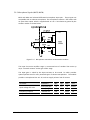
The serial channels consist of two UARTs and a USB port.
These provide
communication links to the application or accessory units.
The serial channels can be used in differing configurations, depending upon the
users requirements and application. In practice, both UARTs can be configured as
either the control interface or the logging interface. Similarly, control and logging
can be carried out simultaneously on the USB interface.
(default) configuration options are described:
However, the common
• UART1 has full RS-232 functionality and is used for all on- and off –line
communication (modem sleep & wake functional control is an integral
component of this interface). Its intended use is that of the primary command
(AT) interface.
• UART2 behaves as a general-purpose serial data link. It can be used for data
logging and de-bugging purposes. It can also be used as a data interface to
peripheral devices, such as a GPS receiver.
• The USB port provides a convenient general purpose peripheral (slave) port for
use with host devices which have USB controllers.
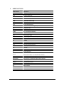
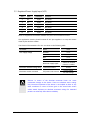
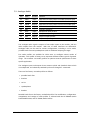
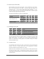
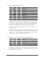
5.11.1 UART1
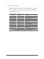
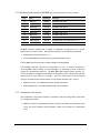
Pin
Name
Direction
Function
53
RI
Output
Ring Indicator
54
DCD1
Output
Data Carrier Detect (UART1)
55
DTR1
Input
Data Terminal Ready (UART1)
57
RTS1
Input
Ready To Send (UART1)
58
CTS1
Output
Clear To Send (UART1)
59
DTM1
Input
Data To Module from host (UART1)
60
DFM1
Output
Data From Module to host (UART1)
56
DSR1
Output
Data Set Ready (UART1)
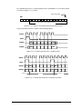
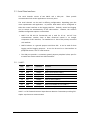
UART1 is a full featured Universal Asynchronous Receiver Transmitter providing fullduplex asynchronous communication.
LZT 123 1836
53