1
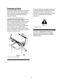
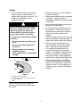
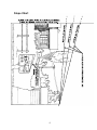
For Serial Nos.
670,000 & Higher
MFG. CO. INC.
®
TM
on the purchase of your new Exmark equipment. This product has been carefully designed and
manufactured to give you a maximum amount of dependability and years of trouble-free operation. If additional information
is needed, or should you require trained mechanic service, contact your authorized Exmark equipment dealer or distributor.
If you need to order replacement parts from your dealer, always give the model number and serial number of your
equipment as well as the part number, description and quantity of the part needed.
The Serial No. plate is located inside the hood of the bagger assembly. For ease of ordering and reference, we suggest
that you record the information requested in the following identification table.
Place Model No. and Serial No. Label Here
(Included in Literature Pack)
or Fill in Below
Date Purchased
Model No.
Serial No.
Part No. 109-6383 Rev B
Introduction
This manual identifies potential hazards and
has safety messages identified by the safety
alert symbol (Figure 2), which signals a
hazard that may cause serious injury or death
if you do not follow the recommended
precautions.
Read this information carefully to learn how to
operate and maintain your product properly
and to avoid injury and product damage. You
are responsible for operating the product
properly and safely.
You may contact Exmark directly at
www.Exmark.com for product and accessory
information or help finding a dealer.
Whenever you need service, genuine Exmark
parts, or additional information, contact an
Authorized Service Dealer or Exmark
Customer Service and have the model and
serial numbers of your product ready.
Figure 1 identifies the location of the model
and serial numbers on the product. Write the
numbers on the front cover.
Figure 2
1. Safety alert symbol.
This manual uses two other words to highlight
information. Important calls attention to
special mechanical information and Note
emphasizes general information worthy of
special attention.
Figure 1
1. Model and serial number plate
2
Specifications
Contents
Model Number:
Introduction ...................................................2
109-5200
Specifications................................................3
Safety............................................................4
Training ...................................................4
Preparation..............................................4
Operation ................................................4
Think Safety First ....................................4
Slopes .....................................................5
Slope Chart .............................................6
Safety and Instructional Decals ...............7
Dimensions
Overall Width with Bagger:
48” Deck: 58.0” (147 cm)
52” Deck: 62.0” (157 cm)
Overall Length with Bagger:
48” & 52”Deck: 95” (241 cm)
Overall Height with Bagger:
48” & 52” Deck: 42.2” (107 cm)
Setup ............................................................8
Installing the Weight ................................8
Installing the Hitch Bracket ......................8
Installing the Hood and Bags...................9
Installing the Boot Mount Bracket
and Tubes .......................................10
Installing the Discharge Baffle
(52” Deck Only) ...............................11
Installing the Bagger Blades ..................11
Operation ....................................................12
Emptying the Grass Bags......................12
Clearing Obstructions
from the Bagger...............................12
Removing the Bagger............................13
Replacing the Discharge Deflector ........14
Operating Tips.......................................14
Maintenance ..............................................16
Recommended Maintenance
Schedule(s) .....................................16
Inspecting the Bagger Attachment.........17
Inspecting the Mower Blades.................17
Caring for the Grass Bags .....................17
Cleaning the Bagger Attachment ...........17
Overall Weight with Bagger:
48” Deck: 734 lbs (333 kg)
52” Deck: 749 lbs (340 kg)
Storage ......................................................17
Storing the Bagger Attachment..............17
Tips and Troubleshooting............................18
Changing Blades ...................................18
3
Safety
•
Please carefully read all of the safety
instructions and decals in the safety section.
Knowing this information could help you,
your family, pets or bystanders avoid injury.
Thoroughly inspect the area where the
equipment is to be used and remove all
stones, sticks, wires, bones, and other
foreign objects which may damage the
equipment or cause personal injury to the
operator or bystanders.
Training
•
Regard the Exmark Bagger as a piece
of power equipment and teach this
regard to all who operate this unit.
•
Before operating your Bagger, carefully
read and understand this manual and
the operator’s manual for your mower in
their entirety. Familiarize yourself with
the controls and the proper use of the
equipment. If the operator(s) or
mechanic(s) can not read English, it is
the owner’s responsibility to explain this
material to them.
•
Do not allow operation of this machine
by untrained personnel. Never allow
children, teenagers, or people unfamiliar
with these instructions to use the
mower. Local regulations may restrict
the age of the operator.
•
Operation
Although hazard control and accident
prevention are partially dependent upon the
design and configuration of the equipment,
these factors are also dependent upon the
awareness, concern, prudence, and proper
training of the personnel involved in the
operation, transport, maintenance, and
storage of the equipment. It is essential that
all Operator Safety Mechanisms be
connected and in operating condition prior to
use for mowing. Refer to the Operator’s
Manual for the mower for additional hazard
control and accident prevention information.
Think Safety First
Avoid mowing while people, especially
children, or pets, are nearby. Keep in
mind that the operator or user is
responsible for accidents or hazards
occurring to other people or their
property.
To avoid personal injury, follow these
procedures:
Preparation
•
•
•
Evaluate the terrain to determine what
accessories and attachments are
needed to properly and safely perform
the job. Only use accessories and
attachments approved by Exmark.
The use of personal protective
equipment, such as (but not limited to)
protection for the eyes, ears, feet, and
head is recommended.
While mowing, always wear substantial
footwear and long trousers. Do not
operate equipment when barefoot or
when wearing open sandals.
4
•
Become familiar with all operating
and safety instruction in the
Operator’s manual for the mower
before using this attachment.
•
Never remove the discharge tube,
bags, bagger top or discharge
deflector while the engine is
running.
•
Always shut the engine off, engage
parking brake, wait for all moving
parts to stop and remove key
before clearing an obstruction from
the bagging system.
•
Never do maintenance or repairs
while the engine is running.
•
Never operate the lawn mower
unless you install a mulch plate,
discharge deflector, or entire grass
collection system.
Slopes
•
Use EXTREME caution when mowing
and/or turning on slopes as loss of
traction and/or tip-over could occur. The
operator is responsible for safe
operation on slopes.
Mowing on wet grass or steep slopes
can cause sliding and loss of control.
•
Progressively greater care is needed as
the slope increases.
•
Always avoid sudden starting or stopping
on a slope. If tires lose traction,
disengage the blades and proceed slowly
off the slope.
•
Avoid sudden starts when mowing uphill.
Mower may tip backwards.
•
Be aware that loss of traction may occur
going downhill. Weight transfer to the
front wheels may cause drive wheels to
slip and cause loss of braking and
steering.
•
Watch for ditches, holes, rocks, dips, and
rises that change the operating angle, as
rough terrain could overturn the machine.
•
Remove or mark obstacles such as
rocks, tree limbs, etc. from the mowing
area. Tall grass can hide obstacles.
•
The operating characteristics of the
machine will change with the Bagger
installed. The stability and traction of the
machine will change as the Bagger fills
with grass clippings. Use progressively
greater care on slopes as the Bagger fills.
•
Always install and remove the Bagger,
including counterweights, as instructed.
Failure to do so will cause a reduction in
stability or traction. Do not operate the
mower with only a portion of the Bagger
installed.
Wheels dropping over edges can
cause rollovers, which may result in
serious injury, death or drowning.
To avoid loss of control and possibility
of rollover:
•
Do not mow near drop-offs or near
water.
•
Do not mow slopes greater than
15 degrees.
•
Reduce speed and use extreme
caution on slopes.
•
Avoid sudden turns or rapid speed
changes.
Figure 3
1. Safe Zone-use the Quest here.
2. Use walk behind mower and/or hand trimmer near
drop-offs and water.
3. Water
Refer to the Slope Chart on page 6 to
determine the approximate slope angle to
be mowed.
5
Slope Chart
6
Safety and Instructional Decals
Safety decals and instructions are easily visible to the
operator and are located near any area of potential
danger. Replace any decal that is damaged or lost.
1
PART NO. 109-6809
LOCATION: Inside Hood on Bracket
1. Crushing hazard of hand—do not remove the whole bagger from the
machine; open the bagger top and then remove the bag(s) from the
bagger. Do not remove the bagger top when it is closed; open the bagger
top and then remove it.
7
Setup
Note: If your mower does not have mounting
holes on the foot rest, position the back of the
weight support assembly on the cross bar
under the foot rest. Center the weight support
assembly and mark the two mounting holes
on the lip of the foot rest. Drill holes using a
13/32” drill bit. Install weight support
assembly as stated in step 1.
Installing the Weight
Parts needed for this step:
Description
Qty.
Nut, Nyloc 3/8-16 Flg ...........................
Weight .................................................
Screw, Button Head 3/8-16 x 1.............
2
1
2
Asm, Weight Support ...........................
Rod, Weight, Lock................................
1
1
2. Insert the weight (item 3) onto the weight
support assembly (item 5).
3. The lock rod (item 6) has a key on one end.
Slide the lock rod through the weight support
assembly, notch in the weight and the oval
hole in the frame bracket.
Procedure:
The front weight installed without the
bagger may cause loss of traction and
steering control or an unstable
condition which could result in injury
or death.
4. Rotate the lock rod to secure it into place.
Install the front weight only when the
bagger is installed.
Installing the Hitch Bracket
Note: The weight support assembly can stay
mounted to the unit when the bagger and
weight are removed.
Parts needed for this step:
Note: The removable weight is heavy.
Use care when lifting it. Make sure that
you can hold it securely before lifting it.
Use caution when positioning your hands
so that you do not set it down on your
hands or fingers.
Description
Nut, Nyloc 3/8-16 Flg ......................... 8
Tube, Bagger.....................................
Bolt, Carriage 3/8-16 x 3....................
Plate, Stiffener...................................
Hitch, Bagger.....................................
1. Attach the weight support assembly
(item 5) to the front panel foot rest with
two 3/8-16 x 1 button head screws
(item 4) and two nyloc nuts (item 2) as
shown in Figure 4.
Front panel foot rest
Weight
Weight support assembly
Oval hole
2
4
2
1
Procedure:
1. Remove the two 3/8-16 carriage bolts at the
rear of each frame rail. Retain for reuse if the
bagger is removed.
Figure 4
1.
3.
5.
7.
Qty.
Bolt, Carriage 3/8-16 x 5.................... 4
Plate, Stiffener................................... 4
2. Nut
4. Screw
6. Weight lock rod
8
2. Install the two 3/8-16 x 5 carriage bolts
(item 1) through the holes on the frame as
shown in Figure 5. Place two stiffeners
(item 2) on the top and bottom of the
bagger tube (item 4) and install on
carriage bolts. Fasten with two nyloc nuts
(item 3); leave loose to aid installation.
Repeat procedure for other side.
Installing the Hood and Bags
Parts needed for this step:
Description
Qty.
Screw, PPH 1/4-20 x 3/4 ................... 2
Asm, Bagger Mount........................... 1
Nut, Nyloc 1/4-20 Flg ......................... 2
Asm, Hood Bagger ............................ 1
Bags.................................................. 2
Procedure:
Operating the mower with the bagger
installed and the front weight removed
may cause loss of traction and
steering control or an unstable
condition which could result in injury
or death.
Install the bagger only when the front
weight is installed.
Figure 5
1.
3.
5.
7.
Bolts
Nuts
Screws
Bagger hitch
2. Stiffener
4. Bagger tube
6. Stiffener
1. Install the bagger mount assembly (item 2)
onto to the hood assembly (item 3) using two
1/4-20 x 3/4 screws (item 1) and nyloc nuts
(item 4) as shown in Figure 6.
3. Align the holes in the bagger tube
(item 4) with the bagger hitch (item 7).
Fasten with hardware and stiffener as
shown in Figure 5; leave loose to aid in
installation.
4. Tighten all hardware.
Figure 6
1. Screws
3. Hood assembly
5. Bagger hitch
2. Bagger mount assembly
4. Nuts
2. Install the mount assembly onto the hitch.
9
Installing the Boot Mount Bracket
and Tubes
If you remove the spring-loaded hood
when it is closed (in the down
position), the hood may suddenly fly
open and you or someone else may be
bruised, pinched, or injured in another
way.
Always open (raise) the hood before
you remove or install it on the quickattach bracket.
3. Install the bags by sliding the bag frame
hooks onto the retaining brackets.
Parts needed for this step:
Description
Qty.
Nut, Nyloc 5/16-18 Flg ......................
Bkt, Boot Mount ................................
Asm, Lower Tube..............................
Bolt, Carriage 5/16-18 x 3/4 ..............
Asm, Upper Tube..............................
1
1
1
1
1
1. Remove the discharge deflector from the
deck. Retain all components for reuse if the
bagger is removed.
2. Install the boot mount bracket (item 2) onto
the deck frame using the 5/16-18 x 3/4
carriage bolt (item 3) and nyloc nut (item 1) as
shown in Figure 9. Bracket may stay on when
converting to side discharge mode.
Figure 7
1. Retaining bracket
2. Bag frame hook
4. Lower the hood onto the bags. Then push
down on both bagger retainer latches until
they lock on the bag frame as shown in
Figure 8.
Figure 9
1.
3.
5.
7.
Nut
Screw
Lower tube
Upper tube
2. Boot mount bracket
4. Mount bracket
6. Rubber latch
3. Insert the tab on the lower tube assembly into
the boot mount bracket as shown in Figure 9.
4. Use the latch on the lower tube assembly to
lock the bracket to the deck. Adjust the
tension on the latch to hold the bracket up to
the deck, yet allow for release by hand.
Figure 8
1. Hood
2. Bagger retainer latches
5. Slip the upper tube into seal of the hood
opening – push in and then pull out so that
the seal is extended outward.
6. Slide the upper tube onto the lower tube and
fasten the rubber latches (Figure 9).
10
Important: The curved part of the blade
must be pointing upward toward the inside
of the mower to ensure proper cutting.
Installing the Discharge Baffle –
52” Deck Only
Parts needed for this step:
Description
Qty.
Baffle, Discharge 52”.........................
1
Bolt, Carriage 5/16-18 x 3/4...............
2
Nut, Nyloc 5/16-18 Flg.......................
2
Procedure:
1. Remove the fasteners in the deck as
shown in Figure 10. Retain for reuse if
the discharge baffle is removed.
+
2. Install the 52” discharge baffle as shown
in Figure 10.
Figure 11
1. Blade
3. Bushing
5. Blade bolt
2. Sail area of blade
4. Spring disk washers
+ Orientation of washers
2. Hold the blade end using a rag or thicklypadded glove (or place a wrench on the top
sheave nut). Install the bushing, two spring
disk washers (cupped side toward the blade)
and blade bolt (Figure 11).
3. Torque the blade bolt to 45-55 ft-lbs
(61-75 N-m).
Figure 10
1. Nut
3. Screw
2. Discharge baffle
Note: This baffle can stay on the machine
while side discharging or mulching.
Incorrect installation of the blade or
components used to retain the
blade cause the blade to come
loose and could seriously injure or
kill you or bystanders.
• Always install the original
Exmark blades, blade bushing,
spring disk washers and blade
bolts as shown.
Note: These parts may be discarded if
mounting to 48” unit.
Installing the Bagger Blades
Parts needed for this step:
Description
Blades, 48” or 52”..............................
Qty.
3
Procedure:
Note: Refer to mower operator’s manual for
blade maintenance.
1. Install the blade onto the spindle shaft
(Figure 11).
11
Operation
4. Install the bags by sliding the bag frame
hooks onto the retaining brackets (Figure 13).
Note: The left and right sides of the machine
are determined while sitting in the seat in the
normal operating position.
Emptying the Grass Bags
Be careful when lifting or handling a grass
bag that is full. To empty the grass bags:
1. Move the motion control levers outward to
neutral position, disengage the power take
off (PTO), engage parking brake, stop the
engine, remove the key, and wait for all
moving parts to stop before leaving the
operating position.
2. Pull up on both bagger retainer latches
until they unlock from the bag frame
(Figure 12). Open (raise) the hood.
Figure 13
1. Screws
2. Bagger mount assembly
3. Hood assembly
4. Nuts
5. Bagger hitch
5. Lower the hood onto the bags. Then push
down on both bag retainer handles until they
lock on the bag frame.
Clearing Obstructions from the
Bagger
Figure 12
1. Hood
2. Bag retainer latches
3. Compress debris into the bags. With both
hands, lift up on the bag and unhook it
from the retaining bracket. Empty the bag.
Repeat the procedure for the other bag.
1. Move the motion control levers outward to
neutral position, disengage the power take off
(PTO), engage parking brake, stop the
engine, remove the key, and wait for all
moving parts to stop before leaving the
operating position.
2. Check the grass bags and empty them if they
are full.
3. Remove and separate the discharge tube and
chute from the bagger hood and mower.
Using a stick or similar object, carefully
remove and clear the obstruction from the
mower, discharge tube, chute, and the hood.
4. After you remove the obstruction, install the
complete bagger system and resume
operation.
12
Removing the Bagger
An uncovered discharge opening will
allow objects to be thrown in
operator’s or bystander’s direction.
Also, contact with blade could occur.
Thrown objects or blade contact can
cause serious injury or kill you or
bystanders.
Never operate mower unless discharge
deflector, or entire grass collection
system, or mulch kit is installed.
1. Move the motion control levers outward to
neutral position, disengage the power take
off (PTO), engage parking brake, stop the
engine, remove the key, and wait for all
moving parts to stop before leaving the
operating position.
If you remove the spring-loaded hood
when it is closed (in the down
position), the hood may suddenly fly
open and you or someone else may be
bruised, pinched, or injured in another
way.
Always open (raise) the hood before
you remove or install it on the quickattach bracket.
4. Open the hood and remove the two bags from
the bag frame hooks (Figure 13).
5. Lift the bagger mount assembly and hood off
the bagger hitch.
Note: The bagger hitch does not have to be
removed from the unit.
2. Unlatch the upper tube and the lower
tube. Remove the upper tube from the
hood seal.
Operating the mower with the bagger
installed and the front weight removed
may cause loss of traction and
steering control or an unstable
condition which could result in injury
or death.
Install the bagger only when the front
weight is installed.
3. Remove the bagger mount bracket from
the deck and retain all hardware see
Figure 9.
Operating the mower with the front
weight installed and the bagger
removed may cause loss of traction
and steering control or an unstable
condition which could result in injury
or death.
Install the front weight only when the
bagger is installed.
Note: The removable weight is heavy. Use
care when lifting it. Make sure that you can
hold it securely before lifting it. Use caution
when positioning your hands so that you do
not set it down on your hands or fingers.
6. Remove the weight on the front of the mower.
Note: The weight support assembly can stay
mounted to the unit when the bagger and
weight are removed.
Note: The boot mount bracket does not
have to be removed from the deck.
7. Store all hardware in a convenient location.
Note: On the 52” deck, the discharge baffle
does not have to be removed from the deck;
you may notice better discharge with it
installed. If removed, replace the original
hardware in the deck holes.
13
Replacing the Discharge
Deflector
An uncovered discharge opening will
allow objects to be thrown in
operator’s or bystander’s direction.
Also, contact with blade could occur.
Thrown objects or blade contact can
cause serious injury or kill you or
bystanders.
Never operate mower unless discharge
deflector, or entire grass collection
system, or mulch kit is installed.
1. Locate items shown in Figure 14.
4. Make sure that the spring and rod are installed
so that the rod is retained from sliding out by
the front bracket and the spring holds the
discharge deflector in the down position. Refer
to (Figure 14) for proper orientation.
Important: The discharge deflector must be
spring loaded in the down position. Lift the
deflector up to test that it snaps to the full
down position.
Operating Tips
Larger Machine with Bagger
Remember that the mower is longer and wider
with this attachment installed. By turning too
sharply in confined places you may damage the
attachment.
Trimming
Always trim with the left side of the mower. Do
not trim with the right side of the mower because
you could damage the bagger’s chute and
discharge tube.
Cutting Height
Do not set the mower cutting height too low
because long grass surrounding the mower can
prevent air from getting under the mower and
entering the bagging system. If enough air
doesn’t get under the mower, the bagging system
will plug.
Cutting Frequency
Cut the grass often, especially when it grows
rapidly. You will have to cut your grass twice if it
gets excessively long.
Cutting Technique
Figure 14
1. Mower deck
3. Discharge deflector bracket
5. Rod
2. Discharge deflector
4. Spring
6. Assembled view
2. Place the discharge deflector on the deck.
3. Orient the spring so that the short leg points
towards the discharge deflector and the
longer leg points towards the deck as
shown in Figure 14. Place spring on rod
and slide rod, straight end, through the front
discharge deflector bracket, discharge
deflector, and rear deflector bracket.
For best lawn appearance, be sure to slightly
overlap the mower into the previously cut area.
This helps reduce the load on the engine and
reduces the chance of plugging the chute and
discharge tube.
Using Bag Liners
Although not required, bag liners may be inserted
into each grass bag to collect clippings and make
disposal more convenient (Figure 15). If you use
a bag liner, remove the filled grass bag and close
the top of the liner. Then pull the liner out the
grass bag or turn the bag upside down while
14
holding the handle on the bottom of the grass
bag, allowing the liner to slide out.
Bagging Long Grass
Excessively long grass is heavy and may not be
propelled completely into the grass bags. If this
happens, the discharge tube and chute may plug.
To avoid plugging the bagging system, mow the
grass at a high height of cut, then lower the
mower to your normal cutting height and repeat
the bagging process.
Bagging Wet Grass
Figure 15
1. Cloth grass bag
2. Bag (liner)
Always try to cut grass when it is dry because
your lawn will have a neat appearance. If you
must cut wet grass, use the conventional side
discharge feature of the mower. Several hours
later, when the clippings are dry, install the
complete bagger attachment and vacuum up the
grass clippings.
Bagging Speed
Signs of Plugging
Most often you will bag with the mower
throttle in the Fast position and drive at a
normal ground speed. However, in extremely
dry and dusty grass, you may want to slightly
reduce the throttle speed and increase the
ground speed of the mower. The bagging
system may plug if you drive too fast and the
engine speed gets too slow. On hills it may be
necessary to slow the mower ground speed.
This helps maintain the engine speed and
bagging efficiency.
As you are bagging, a small amount of grass
clippings normally blow out the front of the
mower. An excessive amount of clippings blowing
out indicates that the bags are full or the system
is plugged.
As the bagger fills, extra weight is
added to the back of the machine. If
you stop and start suddenly on hills,
you may lose traction and steering
control or the machine may tip.
•
Do not start or stop suddenly when
going uphill or down hill. Avoid
uphill starts.
•
If you do stop the machine when
going uphill, disengage the PTO.
Then back down the hill using a
slow speed.
•
Do not change speeds or stop on
slopes.
15
Maintenance
Note: The left and right sides of the machine are determined while sitting in the seat in the
normal operating position.
Recommended Maintenance Schedule(s)
Maintenance Service
Interval
Maintenance Procedure
After the first 10 operating
hours
•
Inspect the bagger
Before each use or daily
•
Clean the bagger.
Before storage
•
•
Inspect the bagger.
Clean the bagger.
If you leave the key in the ignition switch, someone could accidentally start the engine
and seriously injure you or other bystanders.
• Remove the key from the ignition and disconnect the wire from the spark plug before
you do any maintenance. Set the wire aside so that it does not accidentally contact the
spark plug.
Debris built up in the engine compartment, if not removed, could be ignited by a hot
engine. A fire in the engine compartment can burn you and others and can damage
property.
• Before using and while the engine is cool, check for debris in the engine compartment.
• Keep the machine free of grass, leaves, or other debris build-up.
• Clean up oil or fuel spillage and fuel soaked debris.
• Allow the machine to cool before storing.
16
Inspecting the Bagger
Attachment
Cleaning the Bagger
Attachment
Inspect the bagger attachment after the first
10 hours of operation, and monthly
thereafter.
1. After each use, remove and wash the
inside and outside of the bagger top,
discharge tube, chute, and the underside
of the mower, using water sprayed from a
garden hose. Use a mild automotive
detergent to remove stubborn dirt.
1. Check the chute, discharge tube, and the
bagger top. Replace these parts if they
are cracked or broken.
2. Make sure you remove matted grass
from all parts.
2. Tighten all nuts, bolts, and screws.
3. Under normal use the bags will
deteriorate and wear. Inspect the grass
bags for deterioration.
3. After washing, let all of the parts dry
thoroughly. Do not wash the grass bags.
Storage
You or bystanders could be severely
injured by flying debris or thrown
objects that may pass through torn,
worn or deteriorated grass bags.
•
Storing the Bagger
Attachment
1. Clean the bagger attachment; refer to
Cleaning the Bagger Attachment.
Frequently check the grass bags
for holes, rips, wear, and other
deterioration.
•
Do not wash the grass bags.
•
If the bag has deteriorated, install
new grass bags supplied by the
manufacturer of this bagger
attachment.
2. Inspect the bagger attachment for
damage; refer to Inspecting the Bagger
Attachment.
3. Make sure the grass bags are empty and
thoroughly dry.
4. Store the bagger in a clean, dry place,
out of direct sunlight. This protects the
plastic parts and extends the life of the
bagger. If you must store the bagger
outside, cover it with a weatherproof
cover.
Inspecting the Mower Blades
Refer to your mower Operator’s Manual for
complete blade maintenance.
Caring for the Grass Bags
Washing the grass bags is not
recommended.
Under normal use the bags will deteriorate
and wear. To prevent rapid deterioration of
the bag material, store the bags where they
will dry completely after each use.
17
Tips and Troubleshooting
1. When the bags get full, there will be
slight blowout from the front right corner
of the deck. Emptying the bags at this
point will minimize the potential for the
tube to plug.
2. If there is excessive blowout from the
deck, check to make sure that the rear
screen in the hood is clear of grass build
up. It is recommended that the screen
and mesh portions of the bags be
cleaned regularly to maintain proper air
flow. This is especially important in wet
conditions.
3. During dry conditions check engine air
cleaners and clean cooling fins more
frequently. The bagger has been
designed to minimize the impact of dust
and debris on the mower, but bagging
can be a dirty environment.
4. During dry conditions, switching to a
lower lift blade may reduce blowout
without hurting quality of cut.
5. Maintaining a ground speed that does not
pull down the engine RPM will allow for
the highest productivity and best quality
of cut. Bogging the engine RPM down by
going too fast will cause plugging and
quality of cut issues.
6. When storing the bagger, it is
recommended that any grass build up in
the tubes be cleaned out.
18
3-Year Limited Consumer Warranty
(30-Day Limited Commercial Warranty)
Exmark Quest Riding Mowers
(For units purchased on or after January 1, 2007)
Consumer Warranty Conditions and Products Covered
Exmark Mfg. Co. Inc. and its affiliate, Exmark Warranty Company,
pursuant to an agreement between them, jointly warrant on the
terms and conditions herein, that we will repair, replace or adjust
any part manufactured by Exmark and found by us (in the exercise
of our reasonable discretion) to be defective in factory materials or
workmanship for a period of three years for residential usage** of
Exmark Quest mowers.
This warranty applies to Exmark Quest mowers purchased on or
after January 1, 2007 sold in the US or Canada. This warranty may
only be assigned or transferred to a second (or third) owner by an
authorized Exmark dealer. The warranty period commences upon
the date of the original retail purchase.
Products
• Attachments
• Belts and Tires
• Battery
• Engine*
Warranty Period
1 year
90 days
1 Year Prorated
3-Year, 3rd Year Covered by Exmark
*Please refer to the manufacturer’s warranty statement that is
included in the literature packet. Exmark Warranty Company
extends coverage for warrantable engine items as defined by the
manufacturer’s original warranty during the 3rd year of warranty.
This warranty only includes the cost of parts and labor.
** Residential usage means use of the product on the same lot as
your home. Use at more than one location is considered
commercial use, and the commercial use warranty detailed below
would apply.
Exmark will cover up to $45 for associated pick-up and delivery
charges to and from any authorized Exmark Service Dealer. This
will apply to the first warrantable service repair only. Additional
transportation charges may apply, contact your Dealer for details.
Limited Warranty for Commercial Use
Exmark Quest mowers and attachments used for commercial,
institutional, or rental use are warranted against defects in
materials or workmanship for the following time periods from the
date of purchase:
Products
Air Cooled Gas Engines
All other items
Warranty Period
90 day limited warranty
30 day limited warranty
Items and Conditions Not Covered
This warranty does not cover the following:
• Pickup and delivery charges to and from any authorized Exmark
Service Dealer beyond first warrantable service.
• Any damage or deterioration due to normal use, wear and tear,
or exposure.
• Cost of regular maintenance service or parts, such as filters,
fuel, lubricants, tune-up parts, and adjustments.
• Any product or part which has been altered or misused or
required replacement or repair due to normal wear, accidents, or
lack of proper maintenance.
• Any repairs necessary due to use of parts, accessories or
supplies, including gasoline, oil or lubricants, incompatible with
the turf equipment or other than as recommended in the
operator's manual or other operational instructions provided by
Exmark.
There are no other express warranties except for engine and
special emission system coverage stated elsewhere herein or
included with the product.
19
All warranty work must be performed by an authorized Exmark
Service Dealer using Exmark approved replacement parts.
Instructions for Obtaining Warranty Service
The product must be registered with original proof of purchase
by an Exmark Service Dealer before obtaining any warranty
service.
Contact any Exmark Service Dealer to arrange service at their
dealership. To locate a dealer convenient to you, access our
website at www.exmark.com. U.S. Customers may also call
402-223-6375.
If for any reason you are dissatisfied with the Service Dealer’s
analysis or with the assistance provided, contact us at:
Exmark Customer Service Department
The Exmark Warranty Company
2101 Ashland Avenue
Beatrice, NE 68310
402-223-6375 or
[email protected]
Owner’s Responsibilities
The Exmark turf equipment, including any defective part, must
be returned to an authorized Exmark service dealer within the
warranty period. This warranty extends only to turf equipment
operated under normal conditions. You must read the operator’s
manual. You must also properly service and maintain your
Exmark product as described in the operator’s manual. Such
routine maintenance, whether performed by a dealer or by you,
is at your expense.
General Conditions
The sole liability of Exmark and Exmark Warranty Company with
respect to this warranty shall be repair and replacement as set
forth herein. Neither Exmark nor Exmark Warranty Company
shall have any liability for any other cost, loss or damage,
including but not limited to, any incidental or consequential
loss or damage.
In particular, we shall have no liability or responsibility for:
• Expenses related to gasoline, oil or lubricants.
• Travel time, overtime, after hours time or other
extraordinary repair charges or charge relating to repairs or
replacements outside of normal business hours at the place
of business of the authorized Exmark Service Dealer.
• Rental of like or similar replacement equipment during the
period of any warranty, repair or replacement work.
• Any telephone or telegram charges or travel charges.
• Loss or damage to person or property other than that
covered by the terms of this warranty.
• Any claims for lost revenue, lost profit or additional cost as
a result of a claim of breach of warranty.
• Attorney's fees.
No Claim of breach of warranty shall be cause for cancellation
or rescission of the contract of sale of any Exmark mower.
Some states do not allow exclusions of incidental or
consequential damages, so the above exclusions and
limitations may not apply to you.
This warranty gives you specific legal rights, and you may
also have other rights which vary from state to state.
SEE EXMARK’S COMPLETE
LINE OF ACCESSORIES
RIDING ACCESSORIES
CUSTOM RIDE SEAT SUSPENSION SYSTEM
DECK LIFT ASSIST KIT
HITCH KIT
LIGHT KIT
MICRO-MULCH SYSTEM
ROLL OVER PROTECTION SYSTEM (ROPS)
SNOW BLADE
SUN SHADE
TRASH CONTAINER
TURF STRIPER
ULTRA VAC COLLECTION SYSTEM
ULTRA VAC QUICK DISPOSAL SYSTEM
WALK BEHIND ACCESSORIES
GRASS CATCHER
MICRO-MULCH SYSTEM
STEERABLE SULKY
SULKY HITCH KIT
TURF STRIPER
STANDON
Check us out on the Web:
www.exmark.com
© 2007 EXMARK MFG. CO. INC.
INDUSTRIAL PARK BOX 808
BEATRICE, NE 68310
PART NO. 109-6383 Rev. B
(402) 223-6300
FAX (402) 223-5489
ALL RIGHTS RESERVED
PRINTED IN U.S.A.
®
MFG. CO.