1
DVR-5088N
OperatingInstructions
VIDEO CASSETTE RECORDER
•
•
•
•
On Screen Display & Programming
VHS Index Search System
Dt_,ital Auto Tracking
Real Time Counter
CAUTION
Thank you for purchasing DAEWOO VCR, developed to provide advanced features and functions for high quality performance.
To obtain the best results and to avoid malfunction, please read the following instructions carefully before using.
OR MOISTURE. DANGEROUS HIGH VOLTAGES ARE PRESENT INSIDE THE ENCLOSURE. DO NOT
J WARNING: TO
OPEN
REDUCE
THE CABINET
THE RISKREFER
OF FIRE
SERVICING
OR ELECTRIC
TO QUALIFIED
SHOCK, DO PERSONNEL
NOT EXPOSEONLY.
THIS APPLIANCE TO RAIN
CAUTION
1
RISK O_OCKS
l
DO NOT OPEN
J
CAUTION:TO REDUCETHE RISK OF ELECTRIC
SHOCK, DO NOT REMOVECOVER (OR BACK).
NO USER-SERVICEABLE PARTSINSIDE.
REFER SERVICING TO QUAUFIED SERVICE
PERSONNEL.
Warning: To prevent fire or shock hazard, do not expose this unit to rain or moisture.
This video cassette recorder should be used with AC
120V, 60 PIz only.
Caution =To prevent electric shocks and fire hazards,
do NOT use any other power source.
I
polarized plug with an extension cord receptacle or
other outlet unless the blades can be fully inserted
Caution:
prevent
electric shock do not use this
to prevent To
blade
exposure.
Note to CATV System Installer:
This reminder is providedto call the CATV system installer's
attention to Article 820-40 of the NEC that provides
guidelines for proper grounding and, in particular, specifies
that the cable ground shall be connected to the grounding
system of the building, as close to the point of cable entry
as practical.
Caution:
When you are not using the VCR for a long period of time,
it is recommended that you disconnect the power cord from
the AC outlet.
I
The lightning flash with arrowhead symbol,
within an equilateral triangle, is intended to
alert the user to the presence of uninsulated
"dangerous voltage" within the product's
enclosure that may be of sufficient magnitude
to constitute a risk of electric shock to persons.
The exclamation point within an equilateral
triangle is intended to alert the user to the
presence of important operating and maintenance (servicing) instructions in the literature accompanying the appliance.
Caution:
Any changes or modification in construction of the device
which are not expressly approved by the party responsible for
compliance could void the user's authority to operate the
equipment.
NOTE:
This equipmenthas been tested and found to comply with the
limit for a Class B digital device, pursuant to Part "t5 of the
FCC Rules. These limits are designed to provide reasonable
protection against harmful interference in a residential installation.
This equipment generates, uses and can radiate radio frequency energy and if not installed and used in accordance with the
instructions may cause harmful interference to radio communications. However, there is no guarantee that interference
wilt not occur in a particular installation.If this equipment does
cause harmful interference to radio or television reception,
which can be determined by turning the equipment off and on,
the used is encouraged to try to correct the interference by
one or more of the following measures:
--Reorient or relocate the receiving antenna.
--Increase the separation between the equipment and receiver.
--Connect the equipment into an outlet on a circuit different
from that to which the receiver is connected.
--Consult th_ dealer or an experienced radio/TV technician
for help.
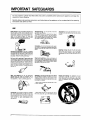
IMPORTANT SAFEGUARDS
For your protection, please read these safely instructions completely before operating the appliance, and keep this
manual for future reference.
Carefully observe all warnings, precautions, and instructions on the appliance, or the one described in the operating
instructions and adhere to them.
USE
Power Sources--This set should be operated only
from the type of power source indicated on the
marking label, If you are not sure of the type of electrical power supplied at your home, consult your
dealer or local power company For those sets
designed to operate from battery power, or other
sources, refer to the operating instructions
Alternate Warning--For the set with a three-wire
grounding type AC plug
This plug will only fit into a grounding type power
outlet This is a safety feature If you are unable to
insert the plug into the outlet contact your electriclan to have a suitable outlet installed Do not defeat
the safety purpose of the grounding plug
Otterloadfeg--Do not overload wail outlets, extension cords Oreorwenience receplaoles beyondtheir
capacity, since this can result in fire or electric
shock.
Grounding or Foferlzatfen--This set is equipped
with a polarized AC power cord plug (a plug having
one blade wider than the other), or with a three-wire
grounding type plug (a plug having a third pin for
grounding). Follow the instructions below
For the set with I polarized AC power cord plug:
This plug will fit into the power outlet only one way
This is a safety feature¸ If you are unable to insert
the plug tully into the outlet, try reversing the plug.
If the plug should still fail to fit, contact your eleotrician to have a sudab_e outlet installed. Do not
defect the safety purpose of the polarized plug by
forcing it in
Object and Liquid Entry--Never push objects of
any kind into the set throughopenings as they may
touch dangerous voltage points or should Out parts
that could result in a fire or electric shock. Never
spill liquid of any kind on the set.
Water and Moieture--Do
not use power-line
operated sets near water--for example, near a
bathtub, washbowl, kitchen sink, laundry tub, in a
wet basement, or near a swimming POoL cot
Ventilation--The slots and openings in the cabinet
are provided for necessary ventilation. To ensure
reliable operation Of the set, and to protect it from
overheating, these slots and openings must never
be blOcked or covered
Attachments--Do not use attachments not recommended by the manufacturer, as they may cause
hazards
Oleantng--Unplug the set from the wall
before cleaning or polishing it. DO not use
cleaners or aerosol cleaners Use a c_oth
dampended with water to clean the exterior
set
outlet
liquid
lightly
of the
/
J
--Never
or other
cover the soils and openings
materials
with a cloth
tP
Accessories--Do
cart, stand,
tail, causing
serious damage
ripod,
bracket,
manofacturer
2,,
not place
the set on an unstable
tripod, bracket,
or table The set may
serious injury to a child or an adult, and
to the set Use only a cart stand
or table
recommended
by the
--Never block the slets and openings by placing
the set on a bed, sofa, rug or other similar surface
Pottabll
Clltt warning--An
appliance
and cart
combination
should be moved
with care. Quick
stops, excessive force,
cause
the appliance
overtum
and uneven SUFfeCeS may
_[nd cart combination
to
Never place 1he set in a conlined space such as
a bookcase, or built-in cabinet, unless proper venilalion
is provided¸
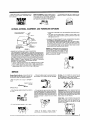
OUTSIDE ANTENNA,
Fower-Cord Protection--Route the power cord so
that it is not likely to be walked On or p{nched by
items placed upon or against them, playing particular attention to the plugs, receptacles, and the
point where the cord exits from the appliance
EQUIPMENT, AND POWERLINE
--Do not place the set near over a radiator or heat
register,
or where it is exposed to direct sunlight
EXPOSURE
c
Mount
house
d
Use
antenna
jumper
discharge
wire not
unit as close
smaller
equivalent,
when a separate
NEC Section 810-21 (I)
than
No
antenna
as possible
6 AWG
grounding
to where lead-in enters
(13.3 mm _) copper,
electrode
or the
is used
See
2 ELIMINATE ANTENNA PROXIMITY TO H_GH VOLTAGEPOWER SOURCES
OR CHANCE OF ACCIDENTAL CONTACT BY iNSTALLER
An outside antenna system should be located where it will never be reach
ed by power lines, e_eetdc light or power circuits and where it will never
contact these power sources if it fails, Ineta_ler should use extreme care
to avoid possible fatal contact by touching power fines, circuits or other
power sources when installing OUtSide antenna
1 ENSURE SAFE ANTENNA AND CABLE CONNECTIONS
It an outside antenna or cable system is connected to provide some protection the antenna or cable system is grounded so as to provide some pro*
teetion against built up static charges and voltage surges• Section 810 of
the Netional Eleetional Code ANSt/NEPA NO 70.1984, provides information
with respect to proper groundingof the mast and suPPOrtingstructure,groundangof the lead-in wire to an antenna discharge unit size of grounding conductors, location of antenna discharge unit, connection to grounding
electrodes and requirements for the grounding electrode:
See figure 1 for items a-d below
a. Use NO 10 AWG (5.3mm 2) aluminum NO.8 AWG (8.4mm 2) NO. 17-AWG
(10ram 2) copper-etad eteel or bronze wire, or larger, as ground wire
b. Secure antenna tead-in and ground wires to house with stand-off insulators spaced from 4 feet (1.22m) to 6 feet (1.83m) apart•
Lightning--For
added protection
for this set during
a lightning storm, or when it is left unattended
and
unused for _dng periods of time, ur_plug it from the
wall outlet and disconnect
the antenna
or cable
system.
This will preveet
damage
lightning
and power-line
surges.
to the set due to
SERVICE
Damage
Requiring
Service--Unplug
the set from
the wall outlet and refer servicing to qualified
service personnel
under the following conditions:
--When
frayed
--If the set has been subject to excessive shock by
being dropped, or the cabinet has been damaged
Servicing--Do not attempt to service the set
yourself as opening or removing covers may expose
you to dangerous voltage or other hazards
Refer all servicing to qualified service personnel,
--If the set does not operate nor really when following the operating instructions Adjust ontythose con
trois that are specified in the operating instructions
Imporper adjustment of other controls may result in
damage and will etffen require extensive work by a
dualgied technician to restore the set to normal
operation
Replacemen!
parts--When
replacement
required,
be sure fhe service
technician
fhe power cord or plug is damaged or
FRAYED OR TAUT
AC LINE
CRACKED
PLUG
--Ifliduid has been spilled or objects have fallen into the set
parts are
has used
replacement
parts specified by the manufacturer
that have the same characteristics
as the original
parts
Unauthorized substitutions
electric shock, or other hazards
may result in fire,
Safety Check--Upon completion of any serwce or
repairs to the set, as the service technician to perform routine safety checks (as specified by the
manufacturer) to determine that the set is in safe
operating condition
--if
the set
has been
exposed
to rain or water
When
the
performance--this
set
exhibits
indicates
a
distinct
change
a r_eed for service
in
Thank you for purchasing
this Daewoo videocassette
recorder. It contains a number of features designed to make
this recorder easy to operate while at the same time capable of producing outstanding
recordings. In the pages that
follow, you'll learn about these features and how to use them. Please take time now to familiarize yourself with the
details of your new VCR, and its various functions and controls.
CONTENTS
1
CAUTION
2
IMPORTANT
6
IDENTIFICATION
SAFEGUARDS
(1) (2) (3)
11
INSTALLATION (1) (2)
14
BASIC OPERATION
--VIDEO
CASSETTE
--PLAYBACK
--SPECIAL
EFFECTS AND OPERATIONS
--RECORDING
--ONE
TOUCH RECORDING
--CLOCK
24
TV PROGRAMS
ADJUSTMENT
PROGRAMMING
THE RECORD TIMER
--DUPLICATION
--TIMER
RECORDING
--CHECKING
AND CANCELLING
INPUT PROGRAMS
--VlSS (VHS INDEX SEARCH SYSTEM)
--CALENDAR
34
SPEAKING
35
TROUBLE
THE
LANGUAGE:
SHOOTING
GUIDE
A GLOSSARY
OF TERMS
IMPORTANT
NOTES
• Audio-visual material may include works of copyright which must NOT be recorded without the authority of the owner
of copyright.
• Note that main voltage is supplied to the unit whenever the main plug is connected to the supply socket.
• Clock display on the front panel indicates that the main supply is on.
• To avoid the risk of fire or electric shock, do not expose the unit to rain or moisture.
• Do not attempt to open the cabinet. There are no user-serviceable
personnel.
parts inside, Refer all servicing to qualified service
• Keep the unit away from radiators or other sources of heat,
Q Do not operate or store the unit close to strong magnetic fields.
• Do not spill liquid of any kind onto the unit. If liquid is accidently spilled onto the unit, immediately remove the main
plug from the supply socket, and consult a qualified service engineer.
MOISTURE
CONDENS&TION:
If you pour a cold liquid
into a glass, water vapor in the air will condense
on the surface
of the glass
This is moisture
condensation
Moisture condensation on the head drum, one of the most crucia_ parts of the video recorder, wLIIcause damage to the tape. Whenever the video recorder
is exposed to extreme cold and heat at the same time, some condensation will occur. When moisture is present, turn the power switch on, and atlow at least
2 hours for the video recorder to dry out
• Use the video recorder in a horizontal (flat) position only.
• Before operating, remove any paper wrapping which may have been affixed to the recorder during manufacture. DO
NOT COVER VENTILATION OPENINGS ON TOP AND SIDES OF THE RECORDER DURLNG OPERATION.
• When a cassette is inserted into the loading compartment, the power is switched on automatically as long as the power
cord is plugged into an AC outlet. DO NOT force a cassette into the compartment when the power cord is unplugged.
• Keep the recorder and video cassette away from strong magnetic fields.
• After playing a video cassette, remove it from the recorder.
DO NOT move the recorder with a cassette in the compartment.
• Store video cassettes in their sleeve or case and position then vertically.
• If a cassette has been subjected to cold temperature, allow it to warm to room temperature before recording or playback.
For your protection, record the model and serial numbers
of your videocassette recorder here. In the event your
recorder requires servicing or is stolen, you may need
this information. You may also wish to clip or staple your
sales receipt to this page.
Model Number:.
Serial Number:
Date Purchased:
Store's Name and Address:
ACCESSORIES
Check to be sure the following items are packed with your VCR.
1. REMOTE CONTROLLER
2. COAXIAL CABLE
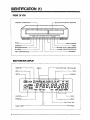
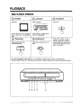
IDENTIFICATION (1)
FRONTOF VCR
CASSE"FFE COMPARTMENT
--- MULTIFUCTION
DISPLAY (DIGITRON)
-I_LI--I_I_
L
POWER
l
REMOTE
SE,,,2.;
STOP/EJECT
L_---.-REC/ONE
REWINDINGJREVIEW
PLAYBACK
CHANNEL
TOUCH TIMER RECORD
SELECTION/TRACKING
PAUSE/STILL
FAST FORWARDING/CUE
MULTI-FUNCTION
DISPLAY
TIMER REC
CLOCK AND REAL TIME COUNTER
WEEKLY
VCR
DAYS
CHANNEL
MO
OFF SLP
L
OTR ERR
i
FUNCTION
PROGRAM
I
--
INDEX
ERROR
ONE TOUCH
TIMER ON/OFF
6
REC
.TAPE SPEED
FUNCTIONINDICATOR
(_) PLAy:
(_ SLOW:
_) CUE:
Q FAST
FORWARDING
(_ REWINDING:
_) REVIEW:
\
I
_) RECORDING:
/
(_) AUTO TRACKING:
©
\
I /
_)EMERGENCY
(_ STILL:
>11
.11-_1>1>-.111>1>-<1<1<1<1
® PAUSE
. "-,[/
-- -- means blinking
/L\
* Malfunction might happen due to external influences,
In that case, emergency sign appears on Multi-Function
Display and press POWER key to re_ease it.
.....
7
IDENTIFICATION (2)
REAL TIME COUNTER
• Real time counter is a numerical guide indicating how much a tape moved in PLAY, REW, FF, or SLOW mode, with
the sign of hour, minute and second displayed on digitron.
EXAMPLE 1) When a tape plays for one hour twenty minutes and fifty five seconds.
0.00.00,
t.20.55,
EXAMPLE 2) When a tape rewinds for the time equivalent to the playing time of twenty five minutes and thirty seconds•
0.0.%00,
]
-n,25.30,
• COUNT RESET
Please reset the counter Into
"
n nn nn by pressing the COUNT RESET button.
u.uu,.uu,
• COUNT _ STOP
This button makes you search easily the 0.00.00.
to page 18)
part of the tape with fast rewinding/forwarding
operation. (Refer
REAR OF VCR
CHANNEL SELECTION SWITCH
AUDIO IN
VIDEO IN
RF OUT--
I
IRC/HRC/STD SELECTION SWITCH
(Refer to the below note)
ANT IN-.VIDEO OUT
POWERCORD
AUDIO OUT
• NOTE: CABLE SYSTEM SELECTION
1. If your cable system includes a converter box supplied by Cable Company, from which you select channels, you
do not need to set the cable select switch on the rear panel of the VCR.
2. If your cable system does not include a converter box, please set the cable selection switch to correspond with
your cable system (HRC, STD, or IRC). Please consult with your Cable Company if necessary to confirm their type
of cable transmission (HRC, STD or IRC).
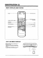
IDENTIFICATION (3)
REMOTECONTROLLER
(1)-BASIC
FUNCTIONS
TVNCR SELECTION
POWER
CHANNEL
DIRECT ACCESS--
TRACKING/CHAN NEL
SELECTION
STOP/EJECT
PAUSE/STILL
SLOW
REWINDING/REVIEW
FORWARDING/CUE
.PLAY
RECORD/ONE
RECORDING
TOUCH
TAPE SPEED
HOWTOUSEREMOTECONTROLLER
• Remote controller can be worked within 7 m
distance from VCR
• Function keys do not work when pressing
several keys at the same time, except for REC
buttons.
• It is advisable to take batteries out of remote
controller when not in use for long time.
9
REMOTECONTROLLER
(2)-ADDmONAL
FUNCTIONS
TV/CATV SELECTION
TV/LINE INPU1
SELECTION
pAU_FJ_nLL
S_Op_.JECT
SLOW
CONTROLLING
SHARPNESS
MULTI-FUNCTION
DISPLAY
ON/OFF
TIMER RECORDING
CLOCK SETTING
--TIMER
CLOcK/T'REC
CLOCK/COUNTER
SELECTION
THE VISS BuTroNs
RELATED TO VISS
(VHS INDEX SEARCH SYSTEM)
10
CLEAR
--(MANUAL
PROGRAMMING
MFT
FINE TUNING)/
RETRACKING
RESET/COUNTER
ZERO STOP
ON SCREEN DISPLAy
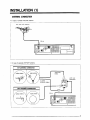
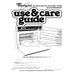
INSTALLATION (1)
ANTENNACONNECTION
• In case of unified VHF/UHF antenna
VHF and UHF Antenna
l
RF IN
IIB_lD_olU,_D
1[
IIIgIIOIIIIII
• In case of separate VHF/UHF antenna
VHF ANTENNA CONNECTION
TWIN-LEAD
CABLE
indoor antenna
UHF, VHF
RECEIVER
75 OHM
COAXIAL CABLE
RF IN
,,
rN,ml UUUUUIUIIIIU
_IolIIIIIIIIIII
_0'_IIIIIIIolIIII
IIIIIIIIIIIIII
.... 11
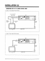
INSTALLATION (2)
CONNECTINGVCR TO TV (1) USINGCOAXIALCABLE
• In Case of TV with separate VHF/UHF terminal
VHF/UHF
SPLITTER
VCR
'Tc_
_|
HDIDOD
oODIDO
VHF ANTENNA
PLUG
CABLE
ANTENNA
r
i
iii
POWER
CORD
POWER CORD
TV
• In case of "IV with unified VHF/UHF terminal
VCR
=Fout
© _'[]
TV ANTENNA
JACK
i
TV
12
ii1'
UUUUUUUUUUUU
IOIlOIIlOIIl
IIIII o IIIII
IIIIIIIIIIII
IIIIIIIIIIII
POWER
CORD
POWER CORD
CONNECTING
VCRTO AUDIO
*REFER
TO
PAGE 12
AUDIO
OUT
TV
I_ E:_:::_'
-
_mill_'_,_
-I_l"'----,'
___
AUDIO IN
POWER CORD
STEREO AUDIO
* NOTE: It is advisable to turn POWER OFF while connecting VCR, TV, as well as Audio.
This VCR is a monoral player. It will not play in stereo even if it is connected to a stereo system.
CONNECTING
VCRTO TV (2)-USINGAN JACK
• In case of TV with AN jacks
COAXIAL
CABLE
AUDIO !
JACK
TV
POWER
VIDEO
JACK
POWER
CORD
CORD
13
BASIC OPERATION
14
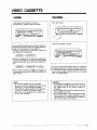
__
VIDEO CASSETTE
LOADING
UNLOADING
Upon inserting the cassette, the power is
automatically on without pressing the button.
Press Eject button.
, ,
Remove the cassette smoothly.
The new motorized load;rig system allows a cassette to
be loaded even when the power has not been turned on,
as long as the AC power cord is plugged in.
• Inserting a cassette with its safety tab in place turns
the recorder on automatically.
[ LOAO!--'lPOWER
NG ONI
• Inserting a cassette with its safety tab removed not
only turns the recorder on, but playback of the cassette
begins automatically, due to the new auto-play function.
J LOADING ]--_1 POWER ON J---'.-[_
• With a cassette inserted, the _
mark appears on
the fluorescent display panel to indicate a cassette has
been inserted.
Notoe:
• An inverted cassette cannot be inserted.
• Be sure to insert the cassette firmly into the slot;
otherwise, it will be automatically ejected.
• The automatic loading mechanism will operate only when the cassette is inserted correctly.
• When the unit is unplugged into a power outlet,
do not insert cassette.
..........
._--
Due to the new motorized unloading system, a cassette can
be unloaded even when the power has been turned off.
• If a cassette is inside, pressing the EJECT button turns
power on automatically and, after ejection of the cassette,
shuts it off automatically.
CAOTION
• If unloading of a cassette is not possible, check to
see whether the TIMER indicator is its. If so, press
the TIMER button so the TIMER indicator extinguishes.
• Do not attempt to pull out the cassette once automatic loading has started.
• Do not insert fingers or any foreign object beyond
the door flaps of the cassette Loadingslot, as this
could lead to injury or damage to the mechanism.
Show special caution with children.
.............................................
15
CASSE-FI-E FORWARDING DIRECTION
(BEGINNING)
(ENDING)
PLAY
• Avoid exposing the cassettes to direct s0nlight. Keep them away from heaters.
• Avoid extreme humidity, violent vibrations or shocks, strong magnetic fields (near a motor, transformer or magnet) and
dustry places.
• Place the cassettes in casette cases and position vertically.
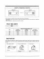
TYPESOF VIDEOCASSE11"E
Use type with the _
mark in this unit.
Maximum
Recording/Playback
Time
Type
SP Mode
(Standard Play)
LP Mode
(Long Play)
SLP Mode
(Super Long Play)
T-160
160 min.
320 min.
480 min,
T-120
120 rain.
240 rain.
360 min.
T-90
90 min.
180 min.
270 min.
T-60
60 rain.
120 min.
180 min.
ERASEPROTECTION
Video cassettes are equipped with a safety tab to prevent accidental erasure. When the tab is removed, recording can
not be performed. If you wish to record on a cassette whose tab has already been removed, use adhesive tape to block
the hole.
• Safety tab-intact cassette
• TOprevent accidental erasure
• To record again
(2
Safety tab
• Break off the tab with a
screwdriver
• Cover the hole with cellophane
tape
PLAYBACK
BASICPLAYBACK
OPERATION
POWER
Power ON
(_
/
-%
LOADING
Insert a cassette
PLAYBACK
Press PLAY
/
PLAy
m
Set "IV channel to 3 or 4, whichever
is not in use in your _ broadcasting
area.
Upon inserting a cassette,power
will be on automatically.
(_
(_) STOP/EJECT
TRACKING
Adjust picture quality with
CH/TRACKING keys
Press once to stop and twice to
eject
* When VCR turned on and a
cassette is inserted, a motor in
VCR is operating for stand-by to
another mode. if you want to stop
watching VCR, please turn off or
eject the cassette•
CHITRACKING
STOP/EJECT
• This VCR automatically adjust tracking. If it is necessary to adjust picture quality, use tracking keys.
• Pressing TRACKING key will indicate -_,_'-(blinking) sign on digitron display and will adjust tracking automatically.
FAST FORWARDING
REWINDING
EJECTING
Press FF key (in STOP mode)
Press REW key (in STOP mode)
Press EJECt key (in STOP mode)
FF
REW
(55
STOP_JECT
TO SET COUNTER MEMORY
Press the COUNTER RESET key at a point which you
may wish to locate later.
The counter will indicate. _],J'],un.t]P,,
13 rlrl I-In
U HLI U .U Us
TO LOCATE SPECIFIC SCENE
Press the COUNTER $ STOP key.
RESt"
@ STOP
The tape will rewind (or fast forward) and stop at about
the a.a _.un n counter reading automatically.
\ I /
-- STOP /
18,
,,,,
I
\
SPECIAL EFFECTS AND OPERATIONS
SPECIAL
EFFECTS
IN PLAYBACK
MODE(BESTINSP+SLPSPEED:.
SOUND
ISMUTED)
(_ TO RAPIDLYLOCATEA
PARTICULARSEGMENT
_
_
• Press the REW or FF Button.
This starts a fast forward or
reverse visual search in the
first step.
(SP: x3, SP: x5)
• Press the REW or FF Button twice.
This starts a fast forward or
reverse visual search in the
second step.
(SP: x7, SLP: x21)
FF
TOVIEWA DOUBLESPEED
PLAYBACK
PICTURE
FF
REW
• Press the PLAY Buttonto return
to playback.
(_)T0 VIEWA STILLPICTURE
(DURINGPLAYBACK)
• Press the PAUSE/STILLButton.
A freeze frame picture of the
playback image appears.
pAUSFJSTILL
REW
• Press the PLAY Button to return to
playback
• Press the PLAY Button to return
to playback
(_) TO VIEW A SLOW
PICTURE
• Press the SLOW button.
SLOW
r_
• The picture will slowly advanced
frame by frame.
O_
®®
®
@®
PLEASE NOTE:
1. In SEARCH and STILL as well as SLOW mode, no sound will be heard.
2. After 5 minute in SLOW mode, PLAY mode will be resumed automatically.
3. Squeezed picture could be seen while switching from search mode to PLAY mode.
This is NOT a sign of malfunction.
4. In SEARCH and STILL as well as SLOW mode, OSD sign cannot be displayed on TV screen.
,,-19
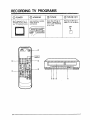
RECORDING TV PROGRAMS
(_
(_
POWER
Set TV channel to 3 or 4
whichever is not in use in
your TV broadcasting area.
f
LOADING
Upon inserting a cassette,
power witl be on
automatically.
(_) TVNCR
(_) TV/LINE KEY
Check that VCR sign on
digitron is lighted (if it is
not on, press TVNCR key
to turn it on).
Press the TV/LINE key to
display CH No, on digitron.
WJLINE
\
0
I
®
--
TV/CATV
Selection
®
I
20
.....
.........
C .....
RECORDING
SPEED
CHANNEL
SELECTION
Select the channel which
you want to record
(from 02-,69)
Select recording speed
(SP or SLP)
Press two REC keys at the
same time, Recording will
start.
Press only one button (REC)
in VCR main body when
recording without using
remote control
SPEED
W_AW
STOP/
RECORDING
_E
FINE TUNING
For fine tuning of your
selected channel, press
MFT button on Remote
control.
INTERRUPTION
STOP/F. JECT
TO RECORD CATV PROGRAM
Adjust with +/- buttons
for the best picture and
sound.
Follow step
In step (_, use TV/CATVbutton and select CATV mode.
(Check that CATV sign on digitron is lighted)
Select the channel which you want to record.
Follow from step (_.
rG1
PLEASE NOTE:
Safety tab-broken tape will be ejected automatically if recording button is pressed.
* Removing the safety tab will protect your recording from accidental erasure. If you wish to record on a cassette
whose tab has already been removed, use adhesive tape to block hole,
RECORDING ONE PROGRAM WHILE VIEWING ANOTHER ON TV
Recordinga program can be done while
j
Follow step (_)-(_)
watching another program on TV.
1
of recording
Use rv's channel selection
by
pressing
_q[
Turn off VCR lamp
TVNCR button
V
switch and
watch the program you want
(meanwhile, the
VCR is recordin
another
program)
.21
ONE TOUCH RECORDING (OTR)
OTR is a very easy and convenient way to immediately start recording a 77/program you happen to be watching without
programming the TIMER. When OTR is complete, the VCR automatically shuts off.
A. INSTANT OTR
Recording starts instantly and the VCR will shut off when
the recording is complete. You can set the recording length
in 30 minute periods up to 4 hours total, or to the end of
the tape.
Occasions for Use:
• For normal recording of TV programs.
• When an unexpected guest or call is received.
• When you are unexpectedly called away from home
OTR Preparations
MAKE SURE THAT....
• the clock is set the correct time.
• the desired tape speed (SP, LP or SLP) is selected.
• the record tab is not missing on the cassette.
• the tape is long enough to record the programs.
REC/OTR
@
OR
COUNTER
(Normal Recording)
r LI. n t't
--[2:3o].-[2:oo]
INSTANTOTR
(_) Cassette In
(_) Selecting Channel
(_
Recording
Insert a safety-tab intact cassette
Select the CH you want to record
Continue to press the REC/OTRButton
until the desired length appears.
/
=
CH/
TRACKING
VCR in stop mode
*To release OTR mode, press the POWER Button.
22:
t__J
Each press of the REC/OTR Button
adds 30 minutes.
Normal Recording_' 0:30--, 1:00...
_4:00-" Normal Recording
CLOCK ADJUSTMENT
Accurate clock time is a must for all types of timer recording.
TO SET THE CLOCK
When the VCR and TV are turned on for the first time,
the clock set guide will appear on the TV screen.
If the guide disappears, press the CLOCK SET Button to recall it.
Be sure that the TVNCR Selector is set to the VCR
position.
• Press TVNCR
buttonand turn
VCR lamp on
• Select "iV
channel to
3or4
TO MAKE CORRECTIONS IN ON-SCREEN ENTRIES
TO make corrections after entering a number, press
the ENTER Buttonto move the flashing indicationone
space left. Enter the correct number. The flashing indicator will then move one space right.
O®
Example: Present Time-10:30 April 6, 1992
®®®®®
(_
Select
the Clock
Set
Mode
• Press CLOCK SET key
Date
(_) Year
(_) Month
• Adjust +1keys to
set YEAR (1992)
• Press ENTER.
• Adjust +/keys to
set MONTH (APR).
• Press ENTER.
\1/
AM 12:00 MON JANI_lg92_
/1%
AM
1_00
WEB"
\1/
JANFg1992
s
AM
I\
12:00
WED
I/
APF_lPIg92
/1\
(_) Hour
(_ Minute
O
• Adjust +/keys to
set HOUR (AM 10:00)
• Press ENTER.
• Adjust +/- keys to
set MINUTES (00:30)
• Press CLOCK SET
key, time indication
on screen will be erased.
"*1/
AM _00MON
APRR419g_
• Adjust +/- keys to
set DATE.
• Press ENTER.
%1/
AM-12fl)0 MON APROn992
/1\
Start the Clock
AM 10:30 MON APRJ6}11_
i
L
23
PROG£AMMtNG
RECORD
ON SCRI_r.NDISPLAY
OSD (On Screen Display) provides convenient visual display of every operationon
TV screen.
I OSD SET Function Button on the Remolo Control
I
1. When it's pressed in basic oderations (Play, Stop, FF/REW,Eject), it will turn OSD
ON and OFF only.
2, When it's press in program set mode, function mode letters will appear onto blue
background.
When pressed once more, function mode letters remain and ficture resumes.
*The RECALL key makes on screen display
RECALL can function in OSD OFF mode.
24
continued
until pressing
it again. OSD
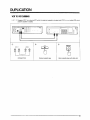
DUPLICATION
VCRTO VCRDUBBING
, .__T_,:._ Suppose VCR 1 is a playing VCR which the original cassette is located and VCR 2 is a recording VCR which
a blank cassette is loaded.
_
_
il
=,. o_d'_
i,
BIL_ I
:
=_
=_l_
={
-_
n:cn:,_:::: ....
,
u:[B=
cJ
YT
I
I
®
VCR 1
@ @
OUTI
II
II
II
£
I
Q
VIOEO
l
IIIIIIIIIIIIIIIIII
IIIIIIIIIIIIIIIIII __
IIIIIIIIIIIIIIIIII _
®
PLAY
RECIOTR
Original cassette tape
Blank cassette tape with safety tab.
VCR 2
@ @
AUDIO
AUDIO
VIDEO
OUTj
]
)i
CONNECTION
25
TIMER RECORDING
The TIMER feature let: you set the VCR with the REMOTECONTROL to do unattended recording(s). For each program you
set, the VCR will turn itself on at the scheduled time, do the recording, and turn off automatically. The types of Timer Recordings you can do are described in the box below. Instructions for each step appear on the T'Vscreen after you select the program mode.
YOU CAN PROGRAM THE TIMER TO:
• Record a program on any day you choose up to one month
away (One Time recording).
• Record once a week at the same time, length and day of
each week (Weekly recording).
• Record everyday at the same time and length (Daily
recording).
MAKE SURE _HAT
•
•
•
•
•
.
the VCR/TV Selector is set to "VCR".
the clock is set to the corrent time.
the desired tape speed (SR LP or SLP) is selected.
the record tab is not missing on the cassette.
the tape is long enough to record the programs.
The TIMER PROGRAMMING funtion allows you to preset programs as long as 1 month in advance and to record upto 8 different programs.
Please Note:
• If it is not necessary to change:
Date, Time, then press ENTER
key to go to next step.
• Turn"IV and V'rR on
®®
®®®®
®®®
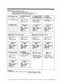
EXAMPLE: Program the TIMER as follows:
Present Time: AM 10:30, April 6th, 1992.
The unattended recording time: May 5th, PM 9:10--PM
Recording content: CH 7 at SLP mode on PGM Na 3
(_
RecordingTime
• Press PGM SET button
PROGRAM
NO
DATE
1
--
SET
ON
-:-
MODE
OFF
-:-
CH
-
2
3
---
-:-:-
-:-:-
-
4
5
---
-:-:-
-:-:-
-
6
7
---
-:-:-
-:-:-
-
8
--
-:-
-:-
-
11:30
SelectingSingle/
(_) Daily/Weekly
Mode
(_ Setting
MonthlDate
• Select PGM 3 with +/key
• Press ENTER key
• Select SINGLE mode
• Set DATE with +/• Press ENTER Key
PROGRAM SET MODE
PGM NO. 3
\
I _
OSD 2
-SINGLE-O_TE \
: APRitglgg2 MON
ON TIME : AM 10:30
OFF TIME: -:CHANNEL:
02
SPEED
: SP
PROGRAM SET MODE
PGM NO. 3
O6D 2
t_
SelectingProgram
No.
with +, - keys
• Press ENTER Key
EINGLE
DATE
ON TIME
OFF TIME
CHANNEL;
SPEED
PROGRAM SET MODE
PGM NO* 3
OSD 2
SINGLE
: A
I 1Sg2 MOb
: A_I_.'_
DATE
:
ONTIME
:
OFF TIME:
CHANNEL:
SPEED
:
: -:02
: SP
(_) Setting Time ON Time
(_) Setting Time OFF Time
• Set HOUR with +/keys
• Preset ENTER key
• Set HOUR with +/keys
• Press ENTER key
PROGRAM SET MODE
PGM NO. 3
ODD 2
SINGLE
DATE
: MAYR_Ig_92 TUE
ON TIME : PM_:30 -OFFTIME:
-:/ I\
CHANNEL:
02
SPEED
: SP
• Set MfNUTE with +/keys
• Press ENTER key
PROGRAM SET MODE
PGM NO. 3
ODD 2
SINGLE
DATE
: MAYF'Jrgg_ "rUE
ON TIME : PM._:J0
OFF TIME : PM:9:-I0"_"
CHANNEL:
02/I \
SPEED
: SP
M _F.d_S92/r
AM'IO:*_
-:-/f
\
02
SP
US
• Set MINUTE with +/keys
• Press ENTER key
PROGRAM SET MODE
PGM NO. 3
OSD2
SINGLE
DATE
: MAYFJ/Ig_ TUE
ON TIME : PM s_la /
OFF TIME: PM _10 -CHANNEL: 02
/I \
SPEED
: EP
keys
;
PROGRAM SET MODE
PGM NO. 3
ODD 2
SINGLE
DATE
: MAYi5/lgS_JTU E
ON TIME : PM 0:10
OFF TIME\_I_
11:30
CHANNEL-_ 02 -SPEED
"_"_P_
i
(_) SettingChannel
• Set CH 7 with +/keys
• Press ENTER key
PROGRAM SET MODE
PGM NO. 3
OSD 2
SINGLE
DATE
: MAYi5/1g02 TUE
ON TIME : PM 9:10
OFF TIME: PM 11:30
CHANNEL;_ q7 /
SPEED
_- SP /
I \
,.:.)Selecting
Recording
Speed
• Set SLP mocle with
+/-
keys
(_) OSD Clear
• Press PGM SET key.
ODD (on-screen-display)
will be disappeared.
_) Set
• Press TIMER key
• Power will be off and
timer sign
will light up.
PROGRAM SET MODE
PGM NO* 3
(Y30 2
SINGLE
DATE
: MAYf541992 TOE
ON TIME : PM 9:10
OFF TIME: PM 11:30
CHANNEL:
07
SPEED
: SLP
Please Note:
In following cases. Timer recording cannot start: 1) When a casette is not loaded.
2) When the safety tab is broken.
27
WHENRECORD
TIMEOVERLAPS
While a program is being recorded, if the next one starts, the rest of the first program is not recorded.
19:00
20:00
21:00
22:00
i
I
I
PROGRAM 1
PROGRAMMING /
--i
I
I
REOORO'NG<IPRooRAMt
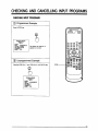
CHECKINGAND CANCELLINGINPUTPROGRAMS
CHECKINGINPUTPROGRAMS
(_
Programmed Example
Press ENTER key
PROGRAM REVIEW
PGM NO. 3
OSD 2
SINGI,EE
DATE
: MAY,_'Igg2tTU E
ON TIME : PM 9-_00
OFF "rIME: PM 11.+_
CHANNEL: 07
SPEED
: S!P
wscltw
The details of PGM No. 3
appears on screen
_r_r_
a
.
'_::_
Unprogrammed Example
Checking PGM No. 1 upon PGM No. 8 with ENTER key.
O®
ENTER
PROGRAM REIVI_
PGM NO. $
OSD2
SlI_LE:
DATE
: MAY,_41_2R'U E
ON TIME : -:OFF tIME:-:CHANNEL: 07
SPEED
: SLP
29
CANCELLING
INPUTPROGRAMS
EXAMPLE: To cancel PGM No. 3 which have been already programed.
@
Ready
(_) Selecting
Press PGM SET key
PGM No
Select PGM No. 3 with +lkeys
@
Cancelling
Press PGM CLEAR key
PGM
CLEAR
PGM
CLEAR
ENTER
÷
PROGRAM
NO DATE
PROGRAM
SETMO_OE
NO
2
3
4
E
E
7
8
DATE
ON
--.MAYI5 P_.I0
_
-:--:--:--:--:-
OFF
CH
...
PI"I_I0
"<,":-,_
-:-:.
_
07
-
PROGRAM SET MODE
FGM NG 3
OEO E
SINGLE
_V_TE : MAYR/IW_TUE
ON11M_ : m_:lO
n_
--------
: SLP
O_
.
O
®
®
3O
-:-:-:.
.:-:-:-:-
.:-;-:.
-:.
-:-:-:-
CH
-
* Press "PGM SET" key to make
PROGRAM SET MODE on
screen disappeared.
_,tANt,IEL: O;'
SPEED
E
3
4
5
e
7
E
SET MODE
ON
OFF
VISS (VHS INDEX SEARCH SYSTEM)
AUTOREGISTER
• When recording starts in normal and timer recording,
INDEX MARK is automatically registered on video cassette
tape.
REC • SP
O:00:00
'MARK'
r_ r'_ r_ O_
(9
• For a few seconds, on-screen-displayed INDEX MARK will
last.
• INDEX MARK does not appear in OTR.
--OSD
(Recall)
®
Please Note:
1. Index Mark cannot be registered on safety-tabless cassette.
2. A program must be recorded for at least for more than 5 minutes to operate VISS,
3, A cassette tape must be fast forwarded for few seconds when recording from the beginning of cassette tape.
*The beginning of a cassette tape is made of Transport tape, Recording and index marking cannot be done on this
part due to absence of magnectic coating.
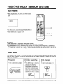
INDEXSEARCH
If the cassette is fully recorded, it will rewind automatically to the beginning and the index circuit will search for each
code cue. When it finds one, the VCR shifts automatically into play mode for six seconds so that you can review the
contents of that segment.
Preparation
(_
• Insert a index marked cassette
which is recorded by this VTR
• Press SEARCH key on the remote
control. A cassette will be
rewound to the beginning
• "i_e index function will automatically search (The VCR will
play the first 6 seconds at every
index marked segment and will
search again, This process will be
repeated at every index marked
segment to the end of a cassette)
Index Search/Play
PLAY • SP
O:00:00
INDEX SEARCH
nO1
(_
To Interrupt
• To interrupt while playing for 6
seconds to watch, press play key.
PLAy
PLAY • SP
O:00:00
INDEX SEARCH
nO1
31
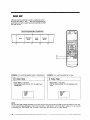
INDEX SKIP
VISS also permits skipping to legate a particular section,
By using the "Index + and -" keys, you can skip the programs you don't want to watch now and concentrale on those
you wish to see.
LWATCHINGBASKETBALL GAME NOWJ
News
Basketball
Game
-1
+1
Soap
Opera
Football
Ga, ,le
+2
+3
®
®
EXAMPLE: From watching basketball game to football game.
Index Skip
• Press INDEX (+) key twice
• VCR will fast fowvard and play from the beginning of
football game
I
O:_:00
INDEX
R 02
FF I_-_-
EXAMPLE: From watching basket ball to news.
2
Index Skip
• Press INDF_.X
(-) key twice
• VCR will rewind and play from the beginning of the
news
REW <1<1
O:00:00
INDtEX
R 02
NOTE
YOUcan play VISS-indexed cassettes on any VCR, and you can play recordings made on other equipment on this VCR,
The on-screen display disappears within a few seconds in "Index Search" and "Index Skip" modes. It can be recalled
by pressing the "OSD Recall" key. Pressing it once more will remove the on screen display.
32
--_
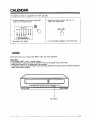
CALENDAR
The centenery calendar
is programmed
from 1991 upto 2090.
• To see the calendar for this month, press PGM
clear key on the remote control
• Select the month you want to view with +lkeys on the remote control
PGM
CLEAR
1992 DEC (12)
SU MO TU WE
1
2
6
7
8
9
13 14 15 16
20 21 22 23
27 28
29 30
TH
3
10
17
24
31
FR
4
11
18
25
SA
5
12
19
26
[+] KEY; NEXT MONTH
[-] KEY; PREVIOUS MONTH
The present month appears
• On screen display disappears
a few seconds
later
CAUTION
When malfunctions
occur, please press 'RESET' button and restart operations.
Please Note:
• Do not press 'RESET' button in normal condition.
• Pressing 'RESET' button will resume the present time and timer programming to initial mode.
• Please refer to page 23-27 to readjust and timer recording.
• If malfunctions keep occuring after 'RESET' button is pressed, please refer to page 35 and 36 'q'rouble shooting guide"
before calling service personel.
J
I II I--I ""I--"I--"I--"I " I--"
l|I_l°l _1'
'i
Reset Button
...........
33
Speakingthe Language:
A Glossaryof Terms
AFT
CATV
_ndex Search
LP
Automatic fine tuning, a circuit that automatically optimizes TV reception.
Cable television.
A feature of this VCR that prints an invisible index number on the tape each time
recording starts, thus making it easy to locate a particular program or segment on a
tape containing a number of segments recorded over a period of time.
Long Play, an intermediate tape recording/playback speed that combines most of the
picture/audio quality obtainable at the standard recording speed with some of the tape
economy of super long play (SLP). (T120=4 hours)
MFT
Manual fine tuning, a feature that lets you optimize TV reception.
OS9
On+screen display of information pertinent to VCR recording or playback. Text designed
to guide you through a function of the VCR or tell you what's happening appears on the
TV screen.
OTR
One4ouch recording, a feature that allows you to record the program you're watching
by pressing a single button. Each touch of the button causes the recorder to record for
a period of 30 minutes.
P/S
Pause/Still-frame control. To stop tape motion temporarily during recording (to eliminate
a commercial in a IV program, for example) or to freeze a video frame during playback,
use this control.
Radio frequency, the composite audio/video signal supplied to a TV receiver (or other
video component) by an antenna or cable system.
The plastic tab at the rear of a videocassette that prevents accidental erasure of a
recording when it is removed. A missing tab may be replaced by plastic or adhesive
tape should you desire to re-use a cassette from which the tab has been removed.
SLP
SP
VlS5
34
Super long play, the slowest recording speed on this videocassette recorder.
Designed to store the maximum amount of program material on a single video
cassette, and for recording when you plan to utilize freeze-frame or slow-motion
playback effects, its use may result in slight loss of picture quality. (1"120=6 hours)
Standard play, the recording speed to use when maximum picture quality is of prime
importance (and when total recording time is not). (T120=2 hours)
VHS Index Search System. A feature of this VCR that automatically records an index
each time recording begins. It helps you locate a particular segment of the tape quickly
and easily.
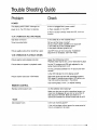
TroubleShootingGuide
Check
Problem
POWER
The display panel is blank. Although the
Is the unit plugged into a power outlet?
power is on, the VCR does not operate.
Is there cassette in the VCR?
If there is excess humidity inside the VCR, it will not
function.
VCR OPERATION
(RECORD
MODE)
Tape does not record.
Is the safety tab on the cassette intact?
Timed recording failed.
Did you set the times correctly?
Did you insert a blank cassette in the machine?
Is the safety tab on the cassette intact?
Is the power indicator (graphic) on?
Picture quality during off-air recording is poor.
Use MFT'(manual fine tuning) key. If additional
adjustment is necessary, use+and-keys.
VCR OPERATION
(PLAYBACK
MODE)
Picture quality during playback is poor.
Adjust the Chfl-racking control
Playback head may be dirty. Use a head-cleaning tape.
Picture does net appear in playback mode.
Are the TV receiver and VCR both adjusted for the
same channel (Channel 3 or 4)?
Are the connectors between the TV set and the VCR
correct?
Is the VCR indicator lit on the display panel?
Picture shows noise bars in Still mode.
Still mode results are best with recordings made at
SLP speed. If recording was made at SP setting, you
may notice some noise bars in the picture.
Use tracking keys (+and-)
REMOTE
to adjust tracking.
CONTROL
Remote control doesn't work
Do the batteries need replacing?
Make sure that you are within operational range--no
more than 30 degrees off axis and no more than 23
feet away from the VCR. Make sure there is no
obstruction between the remote control and the VCR.
TIMER
Clock doesn't work
Is the unit receiving power?
If the unit has been without power for some period of
time, it will need to to be reset.
35
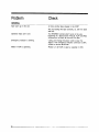
Problem
Check
GENERAL
Tape won't go in the slot.
Is there another tape already in the VCR?
Are you loading the tape correctly, i.e., with the label
side up?
Operation keys don't work.
Emergency indicator is blinking.
Motor in VCR is operating
36.
The REW/REV functions don't work at the very
beginning of a tape and the FF/CUE, PLAY and REC
functions do not work at the end of a tape.
Unplug and replug the power cord to clear the
. signal. If the emergency indicator continues to blink,
contact a service technician.
Please turn off VCR or eject a cassette in VCR.
SPECIFICATIONS
SYSTEM
Video signal
Channel coverage
VHF output
VHS
NTSC color
VHF channel 2-13
UHF channel 14-69
CATV channels A1-A5, A8, A-W, W+ 1-W+84
Channel 3 or 4 (selectable)
signal
VIDEO
Input: Video line in
Output:
Video line out
Signal to noise ratio
Horizontal resolution
AUDIO
Input: Audio line in
Output:
Audio
line out
Frequency response
Signal to noise ratio
Audio Distortion
TAPE TRANSPORT
Tape width
Tape speed
Maximum recording
FF. REW time
time
Phono-type connector 1.0V
75 ohms unbalanced, sync.
Phono-type connector 1.0V
75 ohms unbalanced, sync.
More than 45 dB (SP)
230 lines
(p-p),
negative
(p-p),
negative
Phono-type connector 50K ohms
-10 dBm, unbalanced
Phone.type connector less than 1OK ohms
-5 dBm (More than 47K ohms load), unbalanced
100 Hz-lO KHz (SP)
More than 40 dB
Less than 3% (SP)
12.65 mm (1/2_)
SP : 33.35 mm/sec (11/3"/sec)
LP : 22.23 mm/sec (3/5"/sec)
SLP: 11.12 mm/sec (2/5_/sec)
480 min, with T-160 tape (SLP)
Approx 5 rain 0:-120)
GENERAL
Power requirements
Power consumption
120V, 60Hz AC only
27W
DIMENSIONS
Set size (WxHxD)
Carton size (WxHxD)
Weight
380x85x343
mm (14.9"x3.35"x
13.5")
444x160x412
mm (17.5"x16.2"x6.3
")
6 Kg (13.5 Ibs)
.......
37
Thisinstrument
islistedbyUnderwriters
Laboratories,
Inc.itisdesigned
and
manufactured
tomeetrigidUL.safetystandards
againstx radiation,
fire,
casualty
andelectrical
hazards
LimitedWarranty
Daewoo Electronics Corporation
of America warrants each new electronic product
manufactured by it to be free from defective material and workmanship and agrees to remedy any
such defect or to furnish a new part (at the Company's option) in exchange for any part of any unit
of its manufacture which under normal installation, use and service disclosed such defect, provided the unit is delivered by the owner to us or to our authorized distributor from whom purchased
or authorized service station, intact, for our examination with al! transportation charges prepaid to
our factory. To establish and receive warranty service at our factory or authorized service facilities,
proof of purchase/dated sales invoice is required.
Written authorization must be obtained before any merchandise is returned to the factory
This warranty does not extend to any of our electronic products which have been subjected to
misuse, neglect, accident, incorrect wiring not our own, improper installation, unauthorized modification, or used in violation of in½tructions furnished by us, nor units which have been repaired or
altered outside of our factory, nor to cases where the serial number thereof has been removed,
defaced or changed.
This warranty is in lieu of all warranties expressed or implied and no representative or person is
authorized to assume for us any other liability in connection with the sale of our electronic products
A unil is described as initially defective when the dealer opens the unit and finds that it is inoperative or a customer opening a new unit finds that it is initially defective. This unit may be returned to
the factory by the dealer for exchange. Under no circumstances will a customer be permitted to
return an initially defective unit directly to the factory.
Model
Parts
Labor
Videocassette Recorder
180 days
180 days
For service
information
or assistance
call
toll
free:
f-800.782-4922
OnEWOO
Daewoo
Electronics
100 Daewoo
Corporation
Place • Carlstadt,
of America
NJ 07072