1
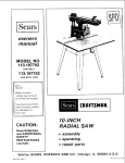
Sears
owners
manual
MODEL NO.
113.19771
SAW ONLY
113.197751
SAW WITH
LEGS
Serial
Number
Model
ar,d serial
number
may be found
at the front
of the base.
You should
record
model
£RRFTSMRN
both
and serial number
in a safe place for
future
use.
IO-INCH
RADIAL
CAUTION:
Read GENERAL
and ADDITIONAL
SAFETY
• assembly
INSTRUCTIONS
• operating
carefully
• repair
SAW
parts
1
Sold
Part
No.
63784
by SEARS,
ROEBUCK
AND
CO.,
Chicago,
IL. 60684
U.S.A.
Pr riled
in USA.
FULL ONE YEAR
WARRANTY
ON CRAFTSMAN
If within
one year from
workmanship,
Sears will
the date of purchase, this Craftsman
repair it, free of charge.
WARRANTY
OR SERVICE
SERVICE
CENTER
IS AVAILABLE
THROUGHOUT
This warranty
gives you
specific
BY SIMPLY
THE UNITED
legal
Radial
RADIAL
SAW
Saw fails due to a defect
CONTACTING
STATES.
THE
NEAREST
rights, and you may have other rights which
in material
SEARS
or
STORE
vary from state to state.
SEARS, ROEBUCK AND CO., Sears Tower, BSC 41 3, Chicago, IL 60684
general
safety
instructions
for power
tools
1. KNOW YOUR POWER TOOL
Read
and
understand
the
owner's
manual
affixed
to the tool. Learn its applications
as well as the specific potential
hazards
tool.
2. GROUND
arrd
labels
and limitations
peculiar- to this
KEEP
GUARDS
in worMug
atigrlment.
4.
order,
REMOVE
AND
IN
in
ADJUSTING
adjustment
KEYS
KEEP
WORK
Cluttered
must
AREA
teas
not
bp
6. AVOID
and
slippery
CLEAN
benches
due
to
DANGEROUS
wax
nvite
or
accidents
Floor
sawdust,
All
visttor,,
should
from
work
area
8. MAKE
WORKSHOP
with
p_tdlocks,
starter key_
9. DON'T
switches,
or
by
,emoving
10. USE RIGHT
bette_ and safer at the rate for which
or attacfrment
to do a job
it was not
PROPER APPAREL
Do not wea_ loose clothing,
gloves, neckties or jewelry
(rings,
wrist
watches}
to get caught
in moving parts.
Nonslip
footwear
is recommended.
Wear protective
hair covering
to contain
long hair. Roll long sleeves
above the t Ibow.
12. USE SAFETY
GOGGLES
(Head Protection)
Wear Safety goggles (must comply
with ANSI Z87.1)
at all times.
Everyday
eyeglasses
only have impact
resistant
lenses, they are NOT safety glasses. Also, use
face or dust mask if cutting operation
is dusty, and ear
periods
of
setvcing;
blades,
bits. cutters,
17. AVOID
Make
at all times.
and
clean
for
*nstructions
best
for
and
safest
lubricating
and
TOOLS
belgie
when
etc.
changing
ACCIDENTAL
sure switch
accessories
such
as
STARTING
is in "OFF"
position
bqfore
plugging
in,
the
owner's
ACCESSORIES
manual
for
recommended
accessories,
Follow
the instructions
the accessories.
The use of improper
cause hazards.
Serious
cutting
STAND
Do not store
it is necessary
Before
DAMAGED
or if the
PARTS
use of the tool, a guard
or other
part that
should be carefully
checked to ensure that it
properly
and perform
its intended
function.
Check
for alignment
of moving
parts,
breakage
parts,
that
[hat
21. DIRECTION
Feed work
of rotation
is tipped
materials above or near the tool such that
to starrd on the toot to reach them.
further
conditions
other part
or replaced
that accompany
accessories
may
ON TOOL
injury could occur if the toot
toot is accidentally
contacted.
is damaged
will operate
TOOL
Don't
forc_ tool
designed for.
DISCONNECT
20. CHECK
FORCE TOOL
It will do rhe job
_t was designed.
11. WEAR
KIDPROOF
master
sharp
performance
Follow
changirrg accesso, ies
19. NEVER
a safe distance
extended
TOOLS WITH CARE
tools
Consult
AWAY
be kept
and balance
18. USE RECOMMENDED
ENVIRONMENT
Don't
use power
tools in damp or wet locations
or
expose
them to rain. Keep work
area well bighted.
Provide adequate surrounding
work space.
7. KEEP CHILDREN
fooUng
15, MAINTAIN
16.
WRENCHES
during
OVERREACH
Keep proper
and
Form habit of checking
to see that keys and adjusting
wrenches
_re removed
from tool before tLJrnH]g it on
5.
14. DON'T
Keep
proper
or muffs)
Use clamps or a vise to hold work when practical.
It's
safer than qsing 'your hand, frees both hands to operate
tool.
PLACE
and
(plugs
13. SECUREWORK
ALL TOOLS
This tool
Is equipped
with :rn approved
3 conductor
cord and a 3-prong
grounding
type i)log to fit tile
[)roper g_o*mding type receptacle
The g_een con(Joctor
in the cor I _s the grounding
wire. Never connect the
green wire !o a live terminal.
3.
protectors
operation.
of
parts,
binding
mounting,
may affect
its operation.
A
is damaged should be properly
of moving
any
other
guard or
repaired
OF FEED
into a blade or cutter against
of the blade or cutter only.
22. NEVER LEAVE
UNATTENDED
Turn power off
complete
stop.
and
the direction
TOOL RUNNING
Don't
leave
tool
until
it comes
to a
additional
CAUTION:
safety
Always
disconnect
the
instructions
power
cord
before
between
the
carriage, and
are tight.
removing the guard, changing the cutting tool, changing the
set-up
or making
adjustments.
Shut off motor
before
performing layout work on the saw table.
WARNING:
DO NOT CONNECT
POWER
CORD
THE
FOLLOWING
STEPS
HAVE
SATISFACTORILY
COMPLETED:
Assembly
II.
Examination
and operating
familiarity
with
ON-OFF
switch,
elevation
control,
yoke index
and lock bevel
index
and lock,
carriage
lock,
guard
clamp
screw,
spreader and antikickback
device, and miter index and
lock.
III.
and alignment.
Review and understanding
of al! Safety
Operating
Procedures thru-out
manual.
INSTAL
Instructions
Set carriage
lock
before
moving
2.
Bolt the saw to the floor if it tends
slide during normal operation.
and
or
-CAUTION:
DO NOT cycle the motor switch "ON"
and "'OFF"
rapidly, as this might cause the sawblade
to loosen. In the event this should ever occur, allow
the saw blade to come to a complete
stop and
re-tighten the arbor nut normally, not excessively.
the saw.
3.
Mount
the saw so the table
the floor.
to
slip,
is approximately
walk,
39"
above
4.
Mount
the saw so the arm s!opes slightly
downward
the rear so the carriage will not roll forward
due
gravity.
5.
If you attach
any kind of table extensions
over 24"
wide to either end of the saw, make sure you either bolt
the saw to the bench or floor as appropriate,
or support
the outer end of the extension
from the bench or floor,
as appropriate.
MINIMIZE
ACCIDENT
Most
accidents
are
setup
and operating
- Do not leave a long board unsupported
so the spring
of the board causes it to shift on the table. Provide
proper
support
for the workpiece,
based on its size
and the type of operation
to be performed.
Hold the
work firmly against the fence.
to
to
Never use a length stop on the free end or edge of the
workpiece
whether
crosscutting
or ripping.
Never
hang onto or touch the free end of workpiece
when
crosscutting,
or a free piece that is cut off while
power is "ON"
and/or
the saw blade is rotating.
In
short,
the
cut-off
piece
in any
"thru-sawing"
operation
must never be confined
it must
be
allowed to move laterally.
POTENTIAL
caused
by
FAILURE
TO
FOLLOW
instructions:
(A) GENERAL
-Avoid
cotfld
--Make
sure your fingers do not contact the terminals
when installing
or removing the plug to or from a live
power source.
awkward
hand positions,
where a sudden slip
cause a hand to move into a sawblade or other
- Never
cutting
tool.
Never reach in back of or around the
cutting
tool
with
either
hand to hold
down
the
workpiece,
or for any other reason; DO NOT place
fingers or hands in the path of the sawblade.
Never saw, dado, mold, or rabbet unless
guard is installed and set up as instructed.
DANGER
AND
_
UNDERSTAND
OWNER'S
rlANGE_;
_A_E,v eO_CL[_
FOR
MANUAL
BEFORE
OPERATING
MACHINE
_OT
YOUR
OWN
SAFETY
5 e[v_n
nE_CH
A_OUNO _E _LAOE
I
AVOID
FEED
"
{NJUnYI_TO
DO
MATE _+AL
]
- H any part of this radial saw is missing or should
break,
bend or fail in any way, or any electrical
component
fail to perform
properly,
shut off power
switch,
remove cord from power supply and replace
damaged,
missing and/or failed parts before resuming
operation.
- IF YOUR
SAW MAKES
AN UNFAMILIAR
NOISE
OR
IF
IT
VIBRATES
EXCESSIVELY
CEASE
OPERATING
IMMEDIATELY
UNTIL
THE
SOURCE
HAS
BEEN
LOCATED
AND
THE
PROBLEM
CORRECTED.
-WARNING:
(GAINED
SAW)
TO
REMEMBER
A SECOND
INJURY.
Before
DO
NOT
ALLOW
FAMILIARITY
FROM
FREQUENT
USE OF
YOUR
BECOME
COMMONPLACE.
ALWAYS
THAT
A CARELESS
FRACTION
OF
IS SUFFICIENT
TO INFLICT
SEVERE
starting
work,
verify
that
no
play
exists
on the saw, or climb
near the saw when
the saw with
power
tool
has come to a
switch and put away
-Do
not use any blade or other cutting
tool marked
for an operating
speed lower than 3450 RPM. Never
use a cuttlng tool larger in diameter than the diameter
NOTE
THE
FOLLOWING
DANGER
LABELS
WHICH
APPEAR
ON THE FRONT
OF THE YOKE
AND GUARD:
READ
climb
power
is "ON".
Never leave
"'ON",
or before
the cutting
complete
stop. Lock the motor
the key when leaving the saw.
the proper
TO
column
& column
support,
or in the
that arm, yoke, and bevel locks/clamps
sawblade
is stalled
or jammed,
shut saw "OFF",
remove workpiece,
and check sawblade squareness to
table surface and to the fence, and check for heel.
Adjust as indicated.
LATION
1.
saws
- A large proportion
of saw accidents
is caused by use
of the wrong type blade, dull, badly set, improperly
sharpened
cutting
tools, by gum or resin adhering
to
cutting
tools,
and
by sawblade
misalignment
out-of-parallel
with
the fence. Such conditions
can
cause the material
to stick,
jam (stall the saw) or
"KICKBACK"
at the operator.
NEVER
ATTEMPT
TO FREE A STALLED
SAW BLADE
WITHOUT
FIRST
TURNING
THE
SAW
"OFF".
If the
UNTIL
BEEN
I.
for radial
for which
the saw was designed.
For greatest safety
and efficiency
when
ripping,
use the maximum
diameter
blade for which the saw is designed, since
under these conditions
the spreader
is nearest the
blade.
Never turn your saw "ON"
before clearing
or work surface of all objects (tools, scraps
etc.)
except
the workpiece
and related
support
devices for the operation
planned.
- DO NOT perform
layout, assembly, or setup
the table while the cutting tool is rotating.
Never
perform
any
operation
"FREE
the table
of wood,
feed or
work
HAND".
on
This
term means feeding
the sawblade into the workpiece
or feeding the workpiece
into the sawblade or other
cutting
tool
without
using the fence or some other
device
which
prevents
rotation
or twisting
of the
workpiece
during
the operation.
Never "RIP'"
in the
crosscut position.
Never make a miter cut with the
arm in the 90 ° crosscut position.
Never lower a revol_ing
cutting tool into the table or
a workpiece
without
first locking the Carriage
Lock
Knob.
Release the knob only after grasping the Yoke
Handle.
Otherwise
the cutting
too! may grab the
workpiece
and be propelled
toward you.
The sawblade,
dado,
or other
cutting
tool
must
be
additional
safety
instructions
for radial saws
removed
from
the saw
arbor
before
using the
accessory shaft (rear end of the saw motor).
NEVER
operate the saw with cutting
tools iincluding
sanding
accessories)
installed
on both ends of the saw arbor.
Therefore,
the table)
proper set-up and cutting
or permit
anyone
else
potential
kickback.
(B} RIPPING
Ripping
is cutting with the grain or the tong way of the
board
it is performed
by pushing
the workpiece
along
the fence and thru
the sawblade
(sawblade
parallel to the fence).
1.
"PUSH
work.
STICK"
ripping
must always
blade and the fence
(see pg. 26) for
table top at least 1/8". DO NOT let go of or stop
feeding the workpiece
between
the blade and fence
until
you
have pushed
it completely
past the
antikickbaek
pawls. Otherwise
the workpiece
could
get into the back of the sawblade
and be thrown
violently
from the saw in the direction
opposite
to
the feed direction.
This is the same action
that
would
occur
if the instructions
of the DANGER
be applied
. . . use a
narrow
or short
2.
Whenever
possible,
use the
provides
minimum
obstruction
or push stick as appropriate.
3.
Do not release the workpiece
before operation
is
complete
- push the workpiece
atl the way past the
rear (outfeed or exit) of the sawblade.
4.
Make sure by trial before starting
the cut that the
antikickback
pawls will stop a kickback
once it has
started. Keep points of pawls SHARP!
5.
Use a push stick
when
ripping
short (under
12
inches) or narrow
(under 6 inches wide) workpieces.
6.
CAUTION:
antikickback
7.
A "KICKBACK"
occurs during a rip-type
operation
when a part or all of the workpiece
is thrown
back
violently
toward
the operator.
It can occur when
the workpiece
the sawblade
and the
sawblade
warning
on the guard is aborted.
Do not stand, or
permit
anyone else to stand, in line with the path of
a workpiece
that may be thrown
from the saw in
this manner.
in-rip position
- this
for feeding by hand
Never
reposition
with power "ON".
the
Guard
or
14. Position the saw so neither you,
observer
is forced
to stand
sawblade.
or is grabbed
feed) at the
Ploughing
(Grooving
9.
Position
the nose of the guard
workpiece,
and position/adjust
and spreader devices as instructed.
NEVER
stacking
10. NEVER
piece
piece
cut more
workpieces
than one
vertically.
feed a workpiece
thru
at
a time
another
each workpiece
individually
thru the sawblade, and
completely
beyond the sawblade, before ripping the
next workpiece.
Use push stick if the rip cut is less
than 6'" wide.
pul! the workpiece
thru
the sawblade
- position
your body at the nose (in-feed) side of the
guard: start and complete
the cut from that same
side. This will
pieces.
require
added
CAUTION:
The AKB/Spreader
device will not
stop a kickback in this position, but will act as a
holddown
and as a guard of the out-feed side of
the sawblade.
by
(butting
second piece against trailing
edge of
being cut), even if of the same thickness. Feed
1 1, DO NOT
resawing,
gaining,
coving,
with
the
grain,
are
examples
of rip-type
cuts, The same basic setup
procedures
including
rotation
of the guard and
adjusting
and positioning
of the AKB/Spreader
device
as for
in-rip
or out-rip
cutting,
apply.
However,
since none of these operations
involve
thru-sawing
(sawing through
the workpiece),
there
is no kerf. Therefore
the spreader and AKB pawls
can
only
be lowered
to a position
where
the
spreader just clears the workpiece.
17.
the saw with
table support
for long
12. Plastic and composition
(like hardboard)
materials
may be cut on your saw. However, since these are
usually
quite
hard and slippery,
the antikickback
pawls may not stop a kickback.
the grain)
Top side molding
(shaping)...
to just clear the
the antikickback
piece
with
Top side rabbeting
by
of
the correct
type
for
the workpiece
being cut.
"HEEL"
can be avoided
by
maintaining
the
sawblade exactly parallel to the fence. Grabbing
by
the sawblade
teeth can be caused by heel or by
feeding from the wrong direction
(see "DANGER"
warning
on guard)
it
can be avoided
by
maintaining
parallelism
of sawblade
to fence,
feeding
into
the sawblade
from
the nose of the
guard
only,
by positioning
the spreader
and
antikickback
properly,
and keeping the workpiece
clown on the table and against the fence.
8.
or a casuat
with
the
16. Shaping
of wood with a dado head or a molding
head can be performed
"top-side"
(cutting
tool
basically
vertical and employing
sawblade guard}, or
"edge"
(saw arbor vertical -- cutting tool horizontal
and employing
the Accessory
molding
head
guard).
by the
outfeed
side.
"PINCHING"
is generally
avoided
utilization
of the spreader, and a sharp sawblade
a helper,
in line
15. Use extra care when ripping wood that has a twisted
grain or is twisted or bowed
it may rock on the
table and/or pinch the sawblade.
closes in on the rear (outfeed side) of
(pinching),
binds between
the fence
sawblade
(heel),
teeth
(wrong-way
procedures.
Do not stand,
to stand,
in line with
a
13. When sawing 1/4" or thinner
materials,
follow
at!
normal
ripping procedures
except set sawblade into
Never apply
the feed force to the section
of the
workpiece
that will become the cut-off
(free) piece.
Feed force when
between
the saw
rip with the finished side down (next to
and be especially
attentive
to following
For rip or rip-type cuts, the following
end of a
workpiece
to which a push stick or push board is
applied
must
be square
(perpendicular
to the
fence)
in order that feed pressure applied to the
workpiece
by the push stick or block does not
cause the workpiece to come away from the fence,
and possibly cause a kickback.
18. During
rip and rip type cuts, the workpiece
must
be held down on the table and against the fence
with a push stick, push block, or featherboards.
A
featherboard
is made of solid lumber per sketch.
(C)CROSSCUTTING
1. ALWAYSRETURNTHECARRIAGE
TO THE
FULLREARWARD
POSITION
ATCONCLUSION
OFEACHCROSSCUT
TYPEOPERATION.
Never
remove your hand from the Yoke Handle unless the
carriage
is in this position.
Otherwise
the cutting
tool
may climb
up on the workpiece
and be
propelled toward you.
2.
Place guard
in horizontal
position
and adjust
antikickback
pawls to just clear the top of the fence
or workpiece,
whichever
is higher.
This provides
additional
3.
dadoing or molding,
when the sawblade
be used. See detailed
instructions
that
the dado head, molding
head, and molding
head
guard.
The
use of grinding
wheels,
abrasive
or cut-off
wheels, or wire wheels, can be dangerous and is not
recommended.
(Abrasive
or cut-off
wheels are used
to saw many different
materials
including
metals,
stone, and glass.)
3.
4.
NOTE:
Drill
Chuck:
Do not install or use any twist drill
larger than 1/2-inch
in dia., or longer than 7 inches
in length
or extending
more than 6inches
beyond
the chuck
jaws. Do not install or use any reduced
shank drill except of the spade type (1 inch dia. or
smaller).
"Use for drilling
WOOD
and PLASTIC
only."
Do not overtighten
arbor nut. Use the arbor wrench
to just
"snug"
guarding.
NEVER
gang crosscut
- lining up more than one
workpiece
in front of the fence - stacked vertically,
o_ horizontally
outward
on the table -- and then
pulling
saw thru:
the blade could pick up one or
more pieces and cause a binding or loss of control
and possible injury.
4.
Do not position
the Arm so the operation
you are
performing
permits
the cutting
tool
to extend
beyond the edges of the Table.
5.
-1 op-side dadoing
or molding
across the grain are
examples
of crosscut-type
cuts. The same basic
procedures
including
positioning
of
the
AKB/Spreader
device as for crosscutting,
apply.
guard must
accompany
it.
WEAR
YOUR
(D) ACC ESSORI ES
1.
Use only
34.
recommended
2.
Never operate
this
accessories
saw when
as listed
equipped
on page
with
a dado
head or molding
head unless the molding
head
guard
is installed
see listing
of recommended
accessories.
The only exception
is when "top-side"
electrical
Motor
Specifications
The ArC motor
used in this saw is a capacitor-start,
non-reversible
type having the following
specifications:
Voltage
.............................
Amperes
..............................
Hertz (cycles)
.............................
Phase
................................
RPM ..................................
Rotation
as viewed from saw blade end ....
120/240
11/5.5
60
Single
3450
Clockwise
CAUTION:
operation.
Your
saw is wired
Connect
to a 120V,
15-Amp.
time-delay
motor
is used for
machine
must
for
120V
and use a 15-Amp.
be grounded
the operator
from electric shock.
IF YOU ARE
NOT SURE THAT
PROPERLY
GROUNDED,
HAVE
QUALI
Goggles
are available
IF POWER CORD tS WORN OR CUT,
IN
ANY
WAY,
HAVE
IT
IMMEDIATELY.
If your unit is for use on less than
plug that looks like below.
at Sears
FI ED ELECTR
while
OR DAMAGED
REPLACED
150 volts
3-PRONG
it has a
PLUG
PROPERLY
GROUNDED
OUTLET
15-Amp.
branch circuit and use a
fuse or circuit
breaker.
If the
240V
operation,
connect
to a
15-Amp.
branch circuit
fuse or circuit breaker.
This
power tool operation.
Safety
retail or catalog stores.
connections
POWER SUPPLY
1.
The operation
of any power
tool can result
in foreign
objects
being thrown
into the eyes, which
can result
in
severe eye damage. Always
wear safety goggles complying
with ANSI Z87.1 (shown on Package) before commencing
GROUNDING
PRONG
time-delay
in use to protect
YOUR
OUTLET
IS
IT CHECKED
BY A
ICIAN.
WARNING:
DO NOT PERMIT
FINGERS
TO TOUCH
THE TERMINALS
OF PLUGS WHEN
INSTALLING
OR
REMOVING
THE
PLUG
TO OR FROM
THE
OUTLET.
WARNING:
IF NOT PROPERLY
GROUNDED
THIS
POWER
TOOL
CAN
INCUR
THE
POTENTIAL
HAZARD
OF
ELECTRICAL
SHOCK.
PARTICULARLY
WHEN
USED
IN
DAMP
LOCATIONS
IN PROXIMITY
TO PLUMBING.
IF AN
ELECTRICAL
SHOCK
OCCURS
THERE
IS THE
POTENTIAL
OF A SECONDARY
HAZARD
SUCH AS
YOUR
HANDS CONTACTING
THE SAWBLADE.
This power tool
is equipped
with a 3-conductor
and grounding
type plug which has a grounding
Listed
by
Underwriters'
Laboratories.
The
cord
prong,
ground
conductor
has a green jacket and is attached to the tool
housing
at one end and to the ground prong in the
attachment
plug at the other end.
This plug requires
outlet as shown.
a mating
3-conductor
grounded
type
If the outlet you are planning
to use for this power tool
is of the two
prong
type
DO NOT
REMOVE
OR
ALTER
THE
GROUNDING
PRONG
IN
ANY
MANNER.
Use an adapter
as shown
and always
the grounding
lug to known ground.
It it recommended
that you have a qualified
replace the TWO prong outlet with a properly
THREE
prong
outlet.
connect
electrician
grounded
electrical
connections
An adapter
as shown below is available for connecting
plugs to 2-prong
receptacles.
The green grounding
lug
extending
from
the adapter
must be connected
to a
permanent
ground
such as to a properly
grounded
outlet box.
GROUNDING
/
[ ,o,0,Eo.i ,,0v/ .0vl
LUG
3.
Connections
a.
NOTE:
already
The adapter
illustrated
have a properly
grounded
ELECTRICAL
is for use only if you
2-prong receptacle.
CONNECTIONS
WARNING:
CHANGES
CONNECTIONS
SHOULD
QUALIFIED
ELECTRICIAN.
1.
Changing
a.
Motor
\
IN
BE
b.
ELECTRICAL
MADE
BY
A
Connections
for 240V
The wires
connected
o
A.C.
inside the
as follows:
motor
terminal
box
must
be
(1)
The orange-colored
wire
on number
8 terminal.
(2)
The brown-colored
wire
on number
7 terminal.
Replace the 120V power-cord
plugwith
240V
plug, connecting
the power-cord
black
leads, respectively,
to the two
a (3-blade)
white
and
"hot"
plug
blades - and connecting
the power-cord
wire to the plug ground prong.
grounding
Under normal
home workshop
usage, and if proper
(full) voltage is supplied to the motor, your saw will
operate
efficiently
on t20V,
as connected
at the
factory.
However,
if any of the following
conditions
exists, it will be advisable for you to reconnect the
motor
for
240V
operation
to
obtain
the
efficiency
and performance
for which your saw is
designed:
(1) Heavy-duty
(2)
(3)
b.
operations.
Either
an
circuit
serving
Low
which
undersized
or an overloaded
branch
GROUNDED
the saw motor.
()bILE/
BOX
NO
ADAPTER
voltage
supplied
by the power
source,
the power company
cannot correct.
AVAILABL_
Motor wiring connections
for 120V (as made at the
factory)
are
described
below.
Necessary
reconnections
for 240V operation
are also described
following.
Whenever
changing
connections
from
120V to 240V
or vice-versa, make certain that all
necessary
steps (including
proper
fusing
of the
branch circuit) are completed.
THIS
saw into
Plug your
d.
Make certain the receptacle
is connected
to a 240V
A-C power supply
through
a 240V branch
circuit
having at least a 15-amp. capacity,
and protected
by
a 15-amp. time-delay
fuse or circuit breaker.
l"\
°*°WNLE'_°-I_'
Jn n IIoCZE£o77I 7 I
SAFETY
3-blade
TYPE PLUG
c.
MOTOR
a 240V,
IS
FOR
receptacle.
PROTECTION
NOTE:
This motor
should be blown out, or "vacuumed",
frequently
to prevent
sawdust
interference
with
normal
motor ventilation.
/
Your
saw
motor
is equipped
with
a manual-reset,
thermal-overload
protector
designed to open the power-line
circuit when the motor temperature
exceeds a safe value.
1
PROTECT_
2.
Connections
for 120V
a.
Remove
terminal
nameplate
board.
b.
The wires
shown:
inside
A.C.
cover
of the motor
The
orange-colored
wire
(2)
The
brown-colored
wire
120V
motor
to
expose
must be connected
as
(R_D
(1)
Use the
saw.
from
power-cord
on
on
plug
number
6 terminal.
number
5 terminal.
furnished
with
your
1.
If the protector
opens the line and stops the saw motor,
immediately
press
the saw
switch
to the "OFF'"
position,
and allow the motor to cool.
2. Afler coolingto a safeoperating
temperature,
the
overload
protectorcanbeclosedmanually
by pushing
in theredbuttonon thetopof themotor.If thered
b_ttonwill notsnapintoplaceimmediately,
themotor
is stilltoohotandmustbeallowedtocootforawhile
longer.Insomecases
thismaytake20-30minutes.
(An
audible
clickwill indicate
protector
isclosed.)
3, As soonas the red buttonwill snapinto running
position, the saw may be startedand operated
normally,
position.
4.
5.
6.
by pulling
out
the
saw switch
to
the "'ON"
voltage (such as small size wires in the supply circuit)
or
to an overly-long
supply
circuit.
Always
check
the
connections,
the load and the supply circuit,
whenever
the motor
fails to perform
satisfactorily.
Check wire
sizes and lengths with the table following.
WIRE SIZES
The use of
power.
To
[ABL
No. 12
No.
8
No.
6
OF CONTROLS
6
SWIVEL
LATCH
No. 14
No. 12
No.
8
Up to 100 feet
100 feet to 200 feet
200 feet to 400 feet
FUNCTIONS
3
Wire Size Required
(American Wire Gauge Number)
240 Volt Lines
120 Volt Lines
Length of the
Conductor
may
be traced
to loose
or
overloading,
reduced
input
AND
loss of
prevent
NOTE:
For circuits
of greater length, the wire size must be
increased proportionately
in order to deliver ample voltage
to the saw motor.
Although
the motor
is designed
for operation
on the
voltage and frequency
specified
on motor
nameplate,
normal
loads will be handled
safely
on voltages
not
more than 10% above or below the nameplate
voltage.
Heavy loads, however,
require
that voltage at motor
terminals
equals the voltage specified on nameplate.
LOCATIONS
cord will cause some
a minimum
and to
over-heating
and motor burn-out,
use the table below to
determine
the minimum
wire size (A.W.G.)
extension
cord.
Use only
3 wire extension
cords which
have 3 prong
grounding
type plugs and 3-pole receptacles
which accept
the tools plug.
Frequent
opening of fuses or circuit
breakers may result
if motor
is overloaded,
or if the motor
circuit
is fused
differently
from
recommendations,
Overloading
can
occur if you feed to rapidly or if your saw is misaligned
so that the blade heels. Do not use a fuse of greater
capacity without
consulting
a qualified
electrician.
Most
motor
troubles
incorrect
connections,
any extension
keep this
to
LEVER
SWITCH
WITH
KEY
CLAMP
\
RIP
SCALE
INDICATOR
3
LOCK
HANDLE
7
ACCESSORY
SHAFT
CONTENTS
Guarantee
...................................
General Safety Instructions
for Power Tools
.........
Additional
Safety Instructions
for Radial Saws
.......
Electrical
Connections
..........................
Assembly and Alignment
........................
Unpacking
and Preassembly
.....................
Alignment
Procedure
.........................
assembly
2
2
3
5
8
8
12
Location
and Functions
of Controls
...............
Basic Saw Operations
..........................
Adjustments
to Compensate
for Wear . .............
Trouble
Shooting
............................
Maintenance
and Lubrication
....................
Recommended
Accessories
......................
Repair Parts
.................................
and alignment
..... _÷_
TOOLS
NEEDED
FRAMING
CHECKING
Screwdriver
(medium)
SQUARE
_CC[JRACY
I[_SIDE
REAR
EDGE
7/16-inchwrench
1/2-inch
#2
wrench
wrench
Phillips
Screwdriver
[i:
/_/_
LI_qE
BE TRUE
CIdECKI_
, ACCURACY
OF
OUTSIDE
OF
FRONT
SPACE _
'
BOARDS
TIGHT
MUST
OF
SQUARE
OF
(FENCE,
9i16dnch
BACK
R '4DYED)
C')
--
__
_--_b;C[
_"
"_
/
DR_-,%"
- _
__
AND
---_
ITAgLE
illl
Radial Saw is shipped complete
NOT INCLUDE
Steel Legs.
Model
carton
113.197751
Radial Saw is shipped
but INCLUDES
Steet Legs.
IN
complete
in one
in one
Contents
Separate al! "loose"
parts from packaging materials
and
check each item with "Table
of Loose Parts" to make
for,
before
discarding
any
If any parts are missing, do not attempt
to assemble
radial saw, plug in the power cord, or turn the switch
2
3
4
5
missing
/ALONG
THIS
EDGE
t
HEre
GAP
[S FLIPPED
DOTTED
0£
StIOULD
WHE'q
Ou
OVER
B©UAR_ c
It.,
POSITION
4
RLAP
NO
_!FRE
iS
DOTTED
'_AP
R
,VHEr4
FIID_TD
OVER
POSITION
PREASSEMBLY
113.19771
but DOES
sure all items are accounted
packing material.
BE NO
LAP
RQliARE
DO NOT CONNECT
THE POWER CORD TO
OF POWER.
THIS CORD
MUST
REMAIN
WHENEVER
YOU
ARE
WORKING
ON
the
ON
square
Pencil
Model
carton
on until
correctly.
I
LINE
i:
OV
and Checking
T
_'L[
SHOULD
Pliers
Unpacking
11_'4
[/
_'//___[_
Framing
1.
cm
/
11i!
WARNING:
A SOURCE
UNPLUGGED
THE SAW.
OF
SQUARE
TAB£_
^ND
*"
ON
•_,LOFJO_i__
,THIS EDGE
UNPACKING
20
23
28
31
34
34
35
parts are obtained
arrd are installed
Key
No.
1
2
3
4
5
6
7
Table
of
Loose
Parts
Qty.
Basin Saw assembly ....................
Rear table
...........................
Table spacer .........................
Rip fence ............................
Front table ...........................
Channel, Table Mtg .....................
"Owner's Manual"
. ....................
1
1
1
1
1
2
1
Loose Parts Bag Part No. 63794
(containing the following items):
Rip-Scale Indicator
...................
2
Twin Nut (for attaching rip-scale indicator) .
Machine Screw, Pan Hd.,6-32x7!16"
....
Hex "L" Wrench, 1/4 ..................
Hex "L" Wrench, 3/16 .................
Elevation Crank Assembly ..............
Arbor Wrench
.......................
Shaft Wrench ........................
*Loose Parts Bag Part No. 63795
(containing the following items):
Machine Screw, Pan Hd., 1/4-20 x 1'" . ....
Washer, Steel (Flat), 17/64 x 5/8 x 1/32"
..
Nut,"T"
. ..........................
Screw, Pan Hd. 1/4-20 x 1-3/4" . .........
Nut, Hex 1,/4-20 ......................
Loekwasher, 1/4 .....................
Table Clamp .........................
*Loose Parts Bag Part No. 63796
(containing the following items):
Hex "L"Wrench,
1/8" . ................
Switch Key .........................
L0ekwasher, 5/16"
. ..................
Washer, Flat l l/32 x l/8 x li16"
. .......
Set Screw, Cup Pt. 1/4-20 x 1" . .........
Nut, Lock 5/16 18 ....................
Bolt, Sq. H& 5/16 18 x 3/4" . ...........
Washer, 21/64 × 9/16 x 1/16"
. ..........
Nut, Hex 5/16-18 .....................
*This bag included in Loose Parts Bag No. 63794
2
4
1
1
1
1
1
4
5
1
1
4
4
2
1
1
4
4
1
2
4
2
4
Thefoliowingpartsareincluded
withModel113.197751.
Key
No.
Table of Loose Parts
1
2
3
Qty.
Leg .....................................
Stiffener, L.H .............................
Stiffener, R.H .............................
Loose Parts Bag Part No. 63752
(containing the following items):
- Screw, Truss Hd. 1/4-20 x 5/8 ..............
- Lockwasher, 1/4 External .................
- Lenkwasher, 5/16 External ................
- Nut, Hex 1/4-20 .........................
- Nut, Hex Jam 5/16-18
....................
- Nat, Hex 1/2-13 .........................
- Foot, Leveling ..........................
- Screw, Hex Hd. 5/16-18 x 5/8 ..............
Washer, 11/32 x 11/16 x 1/16 ..............
4
5
5
6
6
6
7
8
9
4
4
4
2
3
40
40
4
40
4
8
4
4
16
4
7
ASSEMBLING
STEEL
I-
LEGS
0
NOTE:
Steel
From among
Legs are furnished
with
the loose parts, find the
o
40
40
40
8
Truss Head Screws. 1/4-20
Lockwashers,
1/4-External
Hex Nuts, 1/4-20
Hex Nuts, 1/2-13
4
Leveling
1.
2.
3.
0
0
STIFFENER
STIFFENER
L.H.
R.H.
Feet
the
Assemble
o
o
x 5/8
Legs as shown.
Two
(2) each of right
and left hand Stiffeners
to the
screws,
length
shown
using 1/4-20
tockwashers
and hex nuts.
Attach
screws,
the four (4) legs to the
Iockwashers
and nuts.
x 5/8"
Stiffeners
truss
head
I°
O
1/4-20
O
t
O
O
I
I
o
O
using
0
O
i
Assemble
0
Model 113_197751.
following
Hardware:
O
O
II
O
O
°1
STIFFENER
SflFFENER
L.H.
R.H.
Install leveling feet as shown. To level steel legs, loosen
nut on inside of leg and turn nut on outside to raise or
lower feet. Adjust all four levelers if necessary, and then
tighten
NOTE:
3
nuts on inside of leg.
These
levelers
adjustment.
are
not
intended
for
1
2
2
height
CAUTION:
Leveling feet must be adjusted
so the saw does
not rock AND so that the arm slopes slightly
downward
to
the
rear so the carriage
will
not rotl forward
due to gravity.
/
1
1
REMOVE
SKIDS
FROMBASE
MOUNTING
SAW
1. From amongthe looseparts,find the following
hardware:
4 HexHeadScrews,
5/16-18
x 5/8
4 Lockwashers,
5/16in.External
Type
16Washers,
11/32ID
8 HexJamNuts,5/1618
2. Place
sawonlegssothatholesinbottomofsawlineup
withholesmarked
X intopoflegs.
3. Installscrews,
washers
andnutsasshown.
If youmour_t
thesawonanyotherCraftsman
base
orflat
bench,makesureElevation
Crankhasproperclearance
to
rotate.Thesawmustbebolteddown.Position
sawtoslope
slightlyrearward,
sowhenthecarriage
isinstalled
it willnot
rollforwardduetogravity.
SA',\,
BABE
W A S H [ P,,---_-_-
R.H.
l
STIFFENER
L.H.
STIFFENER
1
oloo o
LEG
i
Io ooo,
oj
x
x
0
0
o
0
o
]
O
O
O
tFAD
scC
FLAT
LEG
x
x
4L
_
ooo o
J
oI
1
o
o ooo
STIFFENER_1
HEX
ATTACH
NUT
ELEVATION
Be sure setscrew
/_
CRANK.
is tightened
on flat of shaft.
BLOCK
ELEVATION
(TURN
ELEVATE
Remove
ARM
shipping
TO ITS MAXIMUM
block
HEIGHT.
and discard.
lO
CRANK
CLOCKWISE)
assembly
and alignment
BE positive
switch
is "OFF"
thru-out
entire procedure.
REMOVE
CARRIAGE
AND
TAG.
Read and
and
power
cord
unplugged
STOP
SCREW,
LOCKWASHER
understand
warning
tag before
discarcfing.
LOCK
ARM
BEFORE
PROCEEDING.
HOLDING
CARRIAGE
ASSEMBLY
WITH
BOTH
HANDS,
CAREFULLY
START
AND
SLIDE
THE
CARRIAGE
ONTO THE TRACKS.
The assembly must be
held parallel
with
the arm so that all four bearings slide
smoothly
onto the arm, preventing
any excessive strain on
bearings and track.
WARNING:
REINSTALL
CARRIAGE
STOP SCREW
PREVENT
CARRIAGE
FROM ROLLING
OFF ARM.
Check
for
looseness
of
carriage
bearings.
Refer
"Adjusting
Carriage
Bearings"
in
"Adjustments
Compensate
for Wear" Section.
REMOVE
Use
of
SHIPPING
pliers
may
SCREWS
be
AND
TO
to
to
DISCARD.
necessary.
NDERSIDE
IL
REMOVE
SAW
OF
LOCATION
MOTOR
OF TWO
el S.IP,INOSCREW
BLADE.
1.
Tighten
carriage
2.
Loosen guard clamp
lock knob.
3.
Motor shaft has left hand threads. Hold
and rotate arbor wrench down (clockwise).
4.
Remove
shaft nut, outer collar, saw blade,
collar, Set aside and out of the way,
screw,
remove
guard.
shaft
PULL DOWN
TO LOOSEN
wrench
and inner
BLADE
ROTATION
11
""'--
ALIGNMENT
PROCEDURE
IMPORTANT:
IN ORDER TO OBTAIN MAXIMUM
CUTTING
ACCURACY,
THE FOLLOWING
SIX STEPS
MUST
BE
CAREFULLY
FOLLOWED.
BECOME
THOROUGHLY
FAMILIAR
WITH
THESE STEPS SO THAT YOU CAN ALWAYS
MAINTAIN
YOUR
SAW
IN
PROPER
ALIGNMENT.
THE ACCURACY
OF EACH
ADJUSTMENT
IS ALWAYS
DEPENDENT
UPON THE ACCURA C Y OF THE PRECEDING
A DJUS TMENT.
After
following
the 6 step
assembly
procedure
and the Basic Saw operation
Trouble
Shooting
section
if any difficulty
when performing
any sawing operation.
TABLE
MO
S JPPORT
r'4TING
CHANNEL
\
SCREWS
HERE
LOCKWASHER
and
alignment
section
refer to
is experienced
FLAT WASHER
BASE
STEP ONE
NOTE:
The following
adjustment,
performed
properly,
result in the work table being parallel to the arm.
ATTACHING
AND
SUPPORT
CHANNELS.
1.
LEVELING
TABLE
RAILS
THESE
LJSIING
HOLES
Attach
table
mounting
support
channels
with
four
square head 5/16 18 x 3/4 screws, Iockwashers
and flat
washers and nuts. POSITION
SCREWS IN CENTER
OF
channels
to
Release bevel lock lever, move
and rotate the motor to position
down
Lock bevel lock.
bevel index pin to left
saw blade, end of shaft
Unlock
lever
and
hold
position
as shown.
(approximately
50 °
and positior, carriage
arm
control
Slide
the
arbor
n
ndex
release
Position
arm
against
left
stop
miter).
Loosen carriage Jack knob
directly
over left hand channel.
NOTE:
For safety reasons
standard,
stops have been
rotation
of the radial arm.
4.
MOUNT
MOUNTING
CHANNEL
SLOTS,
finger tight to permit
"slip"
against the base when leveling.
2.
will
wrench
o
in accordance
with the UL
provided
to prevent
360 °
handle
between
shaft and mounting
channel to
Carefully
lower the motor
with
the end of shaft is just touching
wrench
should
slide back and
resistance. Tighten screw "A".
end
of motor
act as a feeler gauge.
elevation
crank until
the arbor wrench. The
forth
with
NOTE:
Do qot change this elevation
setting
left and right hand table support
channels
adjusted.
until both
have been
6.
Move arm and carriage to right hand support
channel
and level in the same manner you adjusted the left hand
support channel.
7.
Recheck
both
support
channels
tightening
screws did not affect
adjustment.
8.
Elevate
provide
in
ARBOR WRENCH
SCREW "A"
Move
arm
and carriage
to
support
in the same manner.
to
the
"B"
slight
5.
saw and place motor
clearance for installation
screw
only
and
tighten
make sure that
accuracy
of the
ARBOR WRENCH
vertical
position
to
of front (work)
table.
TABLE MOUNTING
SUPPORT CHANNEL
(LEFT HAND)
SCREW "8"
SCREW "A"
12
assembly
and alignment
FRONT
i/__._IN
UPSIDE
(_G_
INSTALLATION
OF FRONT
(WORK)
DOWN
POSITION)
HOLE FOR TABLE
BOTTOM SIDE
"O'hT O, L';REWS
,_.0, \ABLE
°
,,)
TABLE.
/
TABLE
°
2
i/4-20 x I-3/4'
PAN
Place front table board upside down on a workbench
or
on the floor.
Drive
T-r, ut into the hole that is not
counterbored,
HD.
i/_-20 x _
SCREW
1'
PA_
FLAT17/64"
WASHER
HD.
SCREW
--_/
"_?
FRONT
TABLE
E
2.
3.
Align the counterbored
holes with
matching
holes in
support
channels.
Install
the five
17/64
inch
flat
washers, and four 1/4- 20 x 1 inch Pan-Head machine
screws. Just barely start the cup point set screw and the
one ( 1 ) 1/__ 20 x 1-3/4 inch Pan Head machine screw in
table center holes.
Install
four
one
¼ Iockwasher
(4) screws
and Hex
in the support
Nut
channels
on each of
NUT
LOCKWASHER
the
and tighten.
Lay the rear table board on edge across the front table
to serve as a straightedge.
Sight under this straightedge
to determine
whether
the front
table board is high or
low at its center.
5.
If the front
table is high at center,
first tighten
center (Y, - 20 x t-3/4 inch) hold down screw until
table is level
then tighten the leveling screw until
screw
REAR TAiLE
HOLD
DOW'N
the
the
this
is snug.
If table is low at center, first tighten
the leveling
unti
the table is level - then tighten
the hold
screw
down
scre_.
If table is not h_gh or
center hold down screw
low, tighten
snug.
leveling
screw
FRONT
and
STEP TWO
ADJUSTING
COLUMN
TUBE
NOTE:
following
adjustment
The
IN COLUMN
is very
SUPPORT
CRITICAL.
Al!
future
alignment
procedures
rely on this adjustment
being
performed
correctly.
ALL
LOOSENESS
MUST
BE
REMOVED.
t.
Indux
and lock
arm at 0 ° Miter.
Whi!e holding
the arm with
one hand, hold fingers of
other hand as shown, between column tube and column
support.
Apply
gentle side pressure
to the arm in
opposing
directions.
Any
side to side or rotational
movement
(indicated
If
looseness
requi red,
exists
by arrow)
the
can be felt with
following
adjustments
finger.
are
13
tABLE
_=
BOARD
J_
Loosen (2) V4 20 Gib set screws
rear of the column support,
3.
on the left side at the
Elevate,
and then lower the Arm:
(a) if the column
binds and elevation
is difficult
loosen two 5/16 - 18
plated bolts on front side of the column
support
until
you
achieve
smooth
but firm
elevation.
(b) If the
column
moves side-to-side
within
the column support,
tighten
the two 5/16 -- 18 plated bolts until movement
disappears
- elevation
should be smooth and firm.
4.
Now tighten
the (2) Yf,
20 Gib set screws until no
noticeable
rotational
play exists between Column Tube
and Column Support.
5.
Recheck
elevation
6,
Replace
Column
and re-adjust
Support
B ,OH
PtArED O
if necessary.
trim.
BLADE
ROTATION
1
STEP THREE
SQUARING
TRAVELS
CROSS
CUT
TRAVEL
IN A STRAIGHT
LINE).
1.
Index
but do not
2.
Install saw blade
threads.
(CARRIAGE
SHAFT
lock arm at 0 ° miter.
as shown.
NOTE:
Do not overtightenarbor
to just "snug"
it.
Motor
nut.
shaft
has left
Use the arbor
hand
o
WRENCH
END OF ARBOR
Rf_STING
ON
WRENCH
TABLE
wrench
SAW
BLADE _..__
OCTEF_ COLLAR
ARBOR
14
NUT
__
_INNER
iii
_._
MOTOR
COLLAR
assembly
and alignment
3.
Lower arm until saw blade
Lock the yoke clamp handle
4.
Place a framing
square
on the table
as shown
and
position
the blade and square until the leg of the square
just contacts a tooth of the blade. Mark this tooth.
NOTE:
5.
table.
The framing
"true"
--
(or combination)
see
start
of
square must be
"Assembly
and
Alignment"
method."
section
8
on
p.
for
checking
BEVEL
D
When the carriage is moved back and forth on the arm,
the marked
tooth
should just touch
the square at all
poults.
If marked
tooth
moves into square
or away
from square the following
adjustments
are required:
a.
Loosen
of arm.
b.
Move
tooth
c.
d.
(3) 3/8
-
16 set screws
in arm latch
_HEX
moved along arm in a "cross
Lock arm latch.
cut"
Set miter
"L" WRENCH
manner.
RETIGHTEN
(3) setscrews in arm latch
possible and recheck "cross cut" travel.
indicator
squaring
of
set BOTH
as tight
as
the cross cut travel will
of the 45 ° miter index
on 0 ° position
LOCK
LEVER
at rear
the arm in proper direction
to make marked
follow
edge of square when the saw blade is
NOTE:
This
simultaneously
positions.
e.
just clears the front
and bevel lock lever.
as shown.
CLAMP
6.
Position
the rip (guide)
fence, spacer board and
table board behind the front table board as shown.
7.
Install the two table
them at the rear of
securely.
rear
clamps
in the holes provided
for
the saw base, and tighten
them
NOTE:
The life of your saw table will be lengthened
considerably
if you will cover the front
table with a
fitted
piece of 1/4 inch plywood.
This should be tacked
in place for easy replacement.
Use of such a cover will
allow you to do all cutting
into the cover, rather than
your table top.
WASHER
REAR
FRONT
15
RIP
TABLE
FENCE
STEP FOUR
SQUARING
SAW BLADE
TO {WORK)
TABLE
NOTE:
If alignment
procedure step one was not
this adjustment
can not be accomplished.
1.
performed,
Place a framing
square on the table with the short leg
against the saw blade. Do not allow the square to rest
against a "set*out"
tooth;
it must rest flat against the
blade side.
2.
If the saw blade
is square
with
the table top
RIP FENCE
X
(no visible
gap appears between the saw blade and square) and no
adjustment
is required.
Set bevel indicator
to 0 °
reading.
If the square does not touch the saw blade as
shown {with square leg held firm against the table top),
perform
the following
adjustments:
I
TA'_t E
a.
b.
c.
J/
I
WRONG
Tighten
carriage
Remove
handle
two
#10
Loosen
1/4"
Slightly
tighten
• . . Now tighten
e.
Reinstall
f.
Loosen
with
each of the four screws
each screw tight.
handle
carriage
head screws
Rotate motor
while
holding
saw blade and table top.
d.
RGHT
and adjust
indicator
LOOSEN
THESE
FOUR
Pan
5116-
"L"
Wrench.
firmly against
,
p
removing
Head Screws• Remove handle by removing
socket head screw and Iockwasher.
socket
• f/
,VRONO
lock knob.
cover by
the four
SQUARE
SCREWS
C
18
_
Hex
square
and recheck
_--'_
5/16-18
HEAD
5/16
on 0 ° reading.
IN.
LOCKWASHER/f
lock knob.
HEX
"L"
WR ENCH
NO.
STEP FIVE
SQUARING
BLADE
HEEL ADJUSTMENT.
TO
RIP
(GUIDE)
FENCE
-
LEFT HAND
CARRIAGE
COVER
BLADE
NOTE:
If alignment
procedure
steps two and four were not
performed,
this alignment
step cannot be accomplished.
1.
Position
cmriage
as shown
and tighten
carriage
lock
knob.
Place a framing
square against the rip fence and
the saw blade, as shown.
The long leg of the square
must be hehl firmly
against both the fence and the table
top, and the short leg must not touch any of the teeth
on the saw blade. Check at several points
of blade
rotabon.
2•
If the square does not touch the blade at both
two points as shown, a heel condition
exists.
RIP FENCE
of the
FENCE
FENCE
FENCE
I
_OLIARE
_
H
--_
l
-%
MOFOR
SQUARE
|j
WRONG
U
16
WRONG
SOCKET
SCREW
tR
[_..L
10 PAN
SCREW
HD
assembly
3.
To correct
and alignment
"heel"
condition
proceed
left hand carriage
as follows:
a.
Remove
b.
Loosen
the yoke
clamp
c.
Loosen
(slightly)
the two
d
Rotate
the yoke assembly
until
saw blade and square is eliminated.
e.
Lock yoke clamp
he× head screws.
handle
f,
Recheck
and install
g
Loosen
for "heel"
carriage
cover.
HEX
handle.
hex-head
and
HEAD
SCREWS
screws.
gap between
retighten
carriage
the
the
two
cover.
lock knob.
NOTE:
This alignment
procedure
will simultaneously
both yoke index ng positions
for blade in and out rip.
set
LEFT
SIDE
OF
CARRIAGE
, !
VERTICAL
1.
2.
HEEL
I1k
ADJUSTMENT
WiEh sawblade in 90 ° cutoff
position,
elevate saw and
rotate motor to vertical position
(Blade Horizontal)
and
c_eck for heel. Make sure bevel lock lever is locked.
BEVEL,
lOCKf
" "--T
I
ol
P_ssition square perpendicular
to fence and between
blade and table, as shown lower am1. Do not allow the
square to rest against a "set-out"
tooth, it must rest flat
against the blade side.
CLOC
If the saw blade is parallel with t!le table top {no visible
g,]p appears between
the saw blade and square),
no
adjustment
is requir_:d.
4.
I_ there is a visible gap between saw blade and square, a
bevel heel condition
exists and adjustment
is required.
a.
To correct,
unlock
bevel lock lever, loosen the rear
motor mount
3/8-16 nut until you can rotate Cam,
and then rotate
Can] as shown until gap between
saw blade and square is eliminated.
b.
Tighten
c.
Reposition
nut and bevel
motor
lock lever and recheck.
in crosscut
position.
SQUARE
_E_c_NII _q_,
r_[]
/
TABLE
1
_1 n
RIGHT
J
WRONG
(TURN
CAM
COUNTERCLOCKWISE}
17
'/TR 0 N G
(TUR Iq CAM
CLOCKed1SE}
STEP SIX
1.
INSTALLING
INDICATORS.
NOTE:
AND
The rip
SCREW
ADJUSTING
scales and
RIP
pointers
SCALE
are intended
to
be used for quick
settings.
For greater accuracy,
take direct measurement
between
blade and fence.
a.
Pre-assemble
not remove
carriage
b.
c.
indicator
the two
and twin nut, loosen but do
screws which attach left hand
cover.
Tilt carriage cover and install rip indicator
Tighten carriage attaching
screws.
Loosen
hut
do
not
remove
carriage
lock
as shown.
knob
in
TWIN
right hand carriage cover. Install rip indicator
in the
same mar ner. Tighten
carriage attaching
screws.
k
i
NUT
i
I
With the fence in its normal
position
(next to the
front table), loosen the yoke clamp handle, pult on
swivel latch pin knob and rotate the yoke as shown
to index the yoke 90 ° from the cross cut position.
This will !ocate the saw blade between
the motor
and the fence.
Lock the yoke by tightening
the
yoke clamp handle.
I
TABLE SPACER BOARD
RIP SCALE
INDICATOR
Position
carriage until the edge of the blade, when
spun by hand, just touches the front
face of the
fence. The rip-scale indicator
(on the right hand side
of radial arm) should now read "0" inches on upper
portion
of the blade "In-Rip"
scale. If not, loosen
screws and shift the indicator
until it is aligned with
the "0" mark, then tighten the screws.
NOTE: With the saw blade and fence in the position
shown,
the upper portion
of the blade "In Rip"
scale
is used.
If the fence
is re-located
at the
extreme
rear
blade "In-Rip"
f.
position,
the lower portion
scale would be used.
of
.
®
O
er]
the
CARRIAGE
LOCK KNOB
The blade "Out-Rip"
scale indicator
on the left
hand side of the radial arm is adjusted in essentially
the same manner as the blade "'In-Rip"
indicator,
except the blade should be as shown. With 2 inches
measured
between
the fence and the face of saw
blade, the rip-scale
indicator
should be positioned
to read 2 inches on the upper portion
of the blade
"Out-Rip"
scale.
NOTE:
With the saw blade and fence in the position
shown, the upper portion
of the blade "Out-Rip"
scale is used. If the fence is moved to rear position
(at the rear of rear table) the lower portion
of the
blade "'Out-Rip'"
scale is used.
g.
Loosen the yoke clamp handle,
latch pin knob
and return
the
pull on the swivel
blade to the 90 °
2" - MEASURED FROM FENCE
TO NEAREST BLADE TOOTH
position.
18
I
1
assembly
ALIGNMENT
WARNING:
and alignment
OF SPREADER
NEVER
FOR
POSITION
ANTIKICKBACK
ASSEMBLY
POSITION
ANTIKICKBACK
PAWLS OR SPREADER.
2.
RIPPING.
THE
GUARD
OR
WITH
POWER
ON; NOR
PAWLS
BY
GRASPING
_
i
Install Blade Guard.
a.
Sight
(visually)
to check for proper alignment
of
spreader with saw blade as shown. If the spreader is
not aligned, adjust it as follows:
(I)
Loosen
two
spreader.
(2)
Rotate hex nuts with
is directly
in line with
(3) Tighten
both
hex
nuts,
one
on
fingers until
saw blade.
each
side
of
",_
the spreader
WING
SCREW
hex nuts firmly.
PREADFR
J
ANTI KICKBACK,
SPREADER
ADJUSTING
WING
SCREW
3.
Check
a.
and Adjust
the spreader
TAB
as follows:
Loosen
the antikickback
spreader adjusting
wing
screw and with the "tab"
position
the antikickbaek
and spreader assembly near the bottom
of the blade
and tighten.
OUTSIDE
VIEW
INSIDE
ANTIKICKBACK
FENCE
LOCATIONS
Position
(A) is used for most cutoff
and narrow
ripping
operations.
Position
(B)
is used for
maximum
width
ripping.
Position
(C) is used to achieve maximum
crosscut
capacity in thin work.
Now that you have assembled
and aligned your saw, you
are ready to proceed with operating
controls
section of this
manual.
Refer to trouble
shooting
section if saw does not
perform
satisfactorily
or any problems
should surface after
using the saw.
19
B
--
CA
PAWLS
VIEW
locations
The
and functions
versatility
of
the
Radial
Saw
is due,
of controls
in part,
to
its
controls,
and these are the keys to its successful operation.
Learn to use the controls
for all operations
before actually
start
ng to saw.
A series of six diagrams is located on the top surface of the
arm. These designate the controls that must be used in basic
set-ups
and operating
procedures.
You
should
become
familiar
with these diagrams and the operating
instructions
that follow,
before operating
your saw.
MITER SCALE
INDICATOR
'
2
ARM CONTROL LEVER
BEVEL INDEX LEVER
RIP SCALE tNDLCATOP_
/
6
3
SWIVEL
LATCH LEVER
SWITCH
WITH
KEY
ARM LOCK
ADJUSTING
WHEEL
TABLE CLAMP
<--7
GUARD CLAMP
SCRE'¢V
RIP SCALE
INDICATOR
ELEVATION CRANK
4
CARRIAGE
KNOB
3
LOCK
HANDLE
7
ACCESSORY
ANTIKICKBACK,
ADJUSTING
WING
SHAFT
SCREW
ANTIKICKBACK
AND
SPREADER
ASSEMBLY
BEVEL INDEX
INDICATOR
2O
5
BEVEL LOCK
LEVER
locations
1.
Depth
and functions
of controls
of Cut (Elevation)
a.
The diagram
shows the elevation
crank
used to raise and lower the saw blade.
b.
Clockwise
rotation
raises
the
which
blade
.
saw-blade
bevel-index
is
.
2.
Angle
Example:
When
moving
the arm to a miter
index
[_osition move it slightly
past the desired index position,
then return to the index position
carefully
to index and
lock.
Yoke
indexing
and bevel
indexing
carl be
accomplished
in a similar
manner.
This
indexing
technique
tends to neutralize
any stresses impaired
upon saw components
and contributes
to the high
degree of accuracy
the saw is capable of producing
when operated expertly.
a.
The arm control
lever locks, unlocks
the arm for Left and Right Miter cuts.
b.
The
has positive
and 4E ° Left and
pulling
arm control
With
arm
contro!
automatically
index
After
positioning
push arm contlol
Yoke
Pivot
index
and
positions
arm to the desired miter
lever to locked position.
The bevel lock lever locks the motor
when the motor
is in any position.
release and push to lock.
Power Switch
the
lever
release
to the yoke
Pull lever to
and Key
a.
Insert
key into
switch
lock.
b.
Insert finger under end of switch
out, to turn switch on.
c.
Push lever in to turn
d.
WARNING:
PROVIDED
lever and pull
end
INDEX R,ELEASE
switch
off.
(Ripping)
b.
A swivel latch lever automatically
indexes the yoke
at each 90 ° position,
Pull the spring-loaded
swivel
latchdever
forward
to release this pin.
c.
The yoke clamp
handle
locks
the yoke
to the
carriage in any position.
Pu!l the handle forward
to
release the yoke; push the handle rearward to secure
USE
KEY
Lock
a.
The carriage !ock knob is rotated
clockwise
to lock
the carriage on the radial arm, and counterclockwise
to release it.
b.
When
performing
crosscutting
knob
must
until the carriage
operations
Blade Angle
The two
indexing
THIS
LOCKING
FEATURE
TO PREVENT
UNAUTHORIZED
OF YOUR
SAW,
AND
KEEP
IT
ALWAYS
REMOVE
IN A SAFE
PLACE,
the
until
index
(Bevel)
controls
of the
used in angular
positioning
and
motor,
to provide
the desired
IS
THE
TO
REMOVE
KEY,
HOLD
THUMB
ON
END
OF
LEVER
TO KEEP SWITCH
IN "OFF"
POSITION
AND PULL KEY STRAIGHT
OUT.
he
rotated
is free to travel
along the arm. This knob should be tightened
the operator
is ready to grasp the bevel
handle and make a cut.
a.
The bevel index
lever automatically
indexes
motor
at 0 °, 45 ° and 90 ° . Move bevel index
i"_1
Two controis
are used in this operation.
They are:
the swivel
latch-pin
lever and the yoke
clamp
handle.
carriage
lock
counterclockwise
5.
c.
d.
6.
and
angle,
a.
Carriage
lever
at 0 °
the yoke.
4.
lock
indexes
Right.
The arm is rotated
by
lever to index release position.
lever
released
the arm will
at 0 ° and 45 ° Left or Right.
UNLOCK
LOCK
3.
bevel
to the left while positioning
the blade, then
it. At any other position
it does not engage.
Proper Indexing
Method
Experienced
operators
of
woodworking
equipment,
such as this Craftsman
Radial
Saw, acquire
the habit
of indexing
in one direction
only, whenever
a new setting is made in preparation
for
a different
opeTation.
arm
are:
The bevel-index
scale indicates the angular position
of the motor with respect to horizontal,
from 0 ° to
90 ° in either vertical position.
of Cut (Miter)
radial
angle,
b.
.
counterclockwise
rotation
lowers it. One complete
turn of the handle will raise or lower the saw blade
Ii16-inch.
(bevel)
lever.
/
/
WARNING:
FOR YOUR
OWN SAFETY
ALWAYS
LOCK THE SWITCH
"OFF"
WHEN SAW IS NOT
IN USE. REMOVE
KEY AND KEEP IT IN ASAFE
PLACE
. . . ALSO IN THE EVENT
OF A POWER
FAILURE
(ALL YOUR
LIGHTS
GO OUT) TURN
SWITCH OFF. LOCK IT AND REMOVE
THE KEY
THIS
WILL
PREVENT
THE
SAW
FROM
STARTING
UP AGAIN
WHEN
THE
POWER
COMES BACK ON.
7.
Accessory
-to
the following
chuck,
Sanding
recommended
drum,
accessories:
and Router
adapter.
AND
- to act as a partial
with
the sawbtade
WARNING:
NEVER
POSITION
THE GUARD
OR
ANTIKICKBACK
ASSEMBLY
WITH THE POWER
ON.
NEVER
POSITION
THE
ANTIKICKBACK
PAWLS
BY
GRASPING
THE
PAWLS
OR
SPREADER.
GUARD
)"
and leading
INFEED
PriCE
d
• ni,2
,-'
OF
on
sawblade
and
accidental
side when
contact
ripping,
crosscutting.
b. The antikickback
and spreader assembly must be
adjusted
to accommodate
the thickness
of the
board
being ripped.
A wing screw in the guard
secures the assembly.
SCREW
OUTFEED
SIDE
SPREADER
MINIMUM
GUARD
1.
in
guard regarding
at the outfeed
edge when
_.
NOSE
closing
a.]'he
blade guard is positioned
by loosening
the
guard clamp screw and rotating
the guard so that
the "nose"
just clears the workpiece
as shown.
\
DIRECTION
from
"Wrong-way
feed" occurs when the teeth themselves
cut, or attempt
to cut, a kerf in the workpiece.
This
differs from a "kickback"
which is generated by the
sides (one or both) of the teeth, because of binding
between
the fence (heel), pinching of the sides of the
sawblade (failure
to use spreader),
and!or inadequate
set of teeth of sawblade.
CAUTION:
The sawblade,
dado, or cutting
toot must
be removed
from
the
saw arbor
before
using the
accessory shaft. NEVER
operate
the saw with cutting
tools (including
sanding accessories)
installed
on both
ends of the saw arbor.
POSITIONING
GUARD,
ANTIKICKBACK
SPREADER
ASSEMBLY,
FOR RIPPING
prevent
kerf
possible kickback;
to prevent
"wrong-way
feed".
"Wrong-way
feed" is
feeding the workpiece
- when sawblade
is in a rip
position
into the outfeed
side of the cutting tool
(sawblade,
dado,
molding
head, etc.),
the side
containing
the antikickback/spreader.
This can be
extremely
hazardous
because the sawblade may grab
the workpiece
and throw it violently
toward the nose
of the guard (infeed side of the tool). Danger label on
guard.
Shaft
Use only
Drill
Spreader
GUARD
CLEARANCE
ANTIKICKBACK
PAWL
\
The biade guard is positioned
by loosening
the guard
clamp screw and rotating
the guard so that the nose just
clears the workpiece
as shown.
DIRECTION
OF
K
DIRECTION
OF
FEED
This is necessary:
-to
protect
operator
from accidentally
contacting
sawblade radially from the Infeed direction.
-to
hold
down
the workpiece
minimizing
lifting
or fluttering
and/or
--to
-to
2.
light
the
ANTIKICKBACK
workpieces);
minimize
sawdust
thrown
toward
the operator.
3.
minimize
the possibility
of a thin pusher
board
riding up on top of the workpiece
with loss of control
of workpiece.
The
antikickback
and spreader
assembly
ripping
operations
and is adjustable
to
the thickness
of the board being ripped.
in the guard
POSITION
against the table
(particularly
thin
(Make
sure by trial
before
starting
the cut that the
antikickback
pawls will stop a kickback
once it has
started).
Insert
workpiece
alongside
spreader
under
outer
set of pawls by approaching
pawls in the feed
direction.
Push workpiece
sharply in the direction
of a
kickback
(opposite
to direction
of feed).
Readjust
Pawls if they do not stop the kickback
motion
by biting
is used during
accommodate
A wing screw
secures the assembly.
These adjustments
are necessary:
Antikickback
- to stop a kickback
Loosen
the wing
screw
and with
the tab provided,
position
the antikickback
and spreader assembly until
the pawl assumes approximately
the position
shown
above. Tighten the wing screw.
into
if generated.
22
the workpiece.
HA VE YOU FOLL 0 WED ALL SIX S TEPS OF
THE ALIGNMENT
PROCEDURE?
IF YOU
HAVE NOT FOLLOWED
THEM IN THEIR
PROPER
SEQUENCE,
YOU
CANNOT
EXPECT ACCURATE
CUTTING
RESULTS.
THIS EDGE OF BOARD
AGAINST FENCE FOR ALL CUTS
FENCE
1
In addition
to the proper alignment
of your saw, you must
also become familiar
with the following
practices
in order
to expect
1.
2.
Workpiece
must
1ST CUT
be as flat
as the
front
board
There
must be no sawdust
or other
wood
between the fence and front table board.
chips
saw.
Turn
4.
There
must be no sawdust
or other wood
underneath
workpiece
or between
workpiece
fence.
5.
Workpiece
must be held tightly
against fence . ..
this is especially
important
when making angle cuts
because the workpiece
has a tendency
to move.
6.
Always
use the
Always
keep it sharp.
7.
//-,I
which
is placed against fence
as the long side of your framing
table
on your
3.
" 1
the best results.
Edge of workpiece
must be as straight
square.
When making
correct
Sawblade
for
the
Job
workpiece
chips
and
pieces
The two
length.
b.
The top and
same length.
c.
Always
place the same edge of the workpiece
against, the fence . . . turn the workpiece
end
for end for the successive cuts and mark a pencit
line on the table for gauging the required length.
pieces
be exactly
GAUGING
the same
must be exactly
for
end
. . . keep
same edge
successive cuts.
!
...
a.
bottom
must
end
I /%
a fou_ sided frame:
side
over
against fence when making
PENCIL LINE FOR
REQUIRED LENGTH
the
3RD
CUT
SCRAP
Deviations
from any of the above practices will
effect on the accuracy of the cuts that you make.
basic saw operations
Basic saw operations
are summarized
into six categories,
explained
and illustrated
in the following
paragraphs.
A
book
entitled
"Power
Tool
Know How
Radial Saw"
is
available
at your
nearest
Store. This book contains
the ,adial saw.
Sears Retail
considerable
Store or Catalog
data applicable
to
NOTE:
Refer
to paragraphs
under
"OPERATION"
illustrations
and descriptions
of controls.
for
23
have an
basic saw operations
REQUIREMENTS
Board
laying
FOR CROSSCUT
position
(stationary)
flat on table top.
against
(OPERATIONS
rip
fence
1 THROUGH
(guide)
and
4)
1.
Arbor
nut must be tight
in horizontal
position.
2.
Arm
3.
Adjust the antikickback
assembly so the pawls just clear
the workpiece
or the fence, whichever
is higher.
4.
Work
must
workpieces
control
and saw blade
lever must be in locked
be held
thicker
firmly
than
guard
installed
position.
against table and fence, For
the fence
is high, install
a
higher
fence
(at least workpiece
thickness}.
Always
place the fence in the most forward
position
(farthest
from
the
column
support)
compatible
with
the
workpiece
being processed
and the operation
being
performed.
With the carriage fully
retracted,
the blade
must not contact
the workpiece
when placed against
the fence, within
the stated capacities of your saw.
5.
Blade should
6.
Hands
7.
Yoke
8.
Bevel index
9.
Blade should
cut into
more than 1/32 inch.
10. Pull
he sharp and correctly
must be kept
clamp
the
handle
set,
well away from
must be in locked
saw blade.
position.
(SEE
PROPER
ITEM "10" AT
LEFT}
lever must be locked.
saw
forward
the
just
table
far
or plywood
cover
not
enough
sever
the
to
lumber.
It is dangerous
if the blade has been pulled too
far out beyond
the piece being cut. When it is returned
it can pick up the right hand piece and throw it over the
fence.
11. For operations
No.
instructions
under
"Blade Angle".
OPERATION
3 and No. 4, observe
paragraph
"Operating
additional
Controls"
No. 1 - CROSSCUT
Crosscutting
is the process of sawing the workpiece
by
pulling
the saw blade through
it and using the fence as a
support
for the edge of the workpiece.
Never crosscut
free-hand.
WARNING:
BEFORE
CROSSCUTTING,
MAKE
SURE
THE
ARM
CONTROL
LEVER,
BEVEL
LOCK LEVER
AND YOKE CLAMP ARE ALL LOCKED.
NEVER
USE A
LENGTH
STOP OR A FIXED
GUIDE
ON THE FREE
END OR EDGE OF A WORKPIECE.
DO NOT CROSSCUT
WORKPIECES
THAT PLACE YOUR
HANDS CLOSE TO
THE
PATH
OF THE
SAW
BLADE.
WHEN
MORE
EXPERIENCE
IS GAINED
BY USING
THE
SAW,
IT
WILL
BE NOTICED,
THAT
WHEN PULLING
THE SAW
TOWARD
YOU DURING
CROSSCUTTING,
THE BLADE
TENDS
TO FEED ITSELF
THROUGH
THE WORK DUE
TO
THE
ROTATION
OF THE
BLADE
AND
THE
DIRECTION
OF
THE
FEED.
THEREFORE,
YOU
SHOULD
DEVELOP
THE HABIT
OF HOLDING
YOUR
RIGHT
ARM
STRAIGHT
FROM
THE SHOULDER
TO
THE WRIST.
(SEE
IMPROPER
ITEM "10" AT
REPETITIVE
LEFT}
CROSSCUTTING
Clamp a "C"
clamp (min. 6 inch) using a wood block on
each side of the arm. This will
limit
the carriage travel
beyond
the position
necessary to complete
the crosscut
operation.
24
basic saw operations
OPERATION
No. 2 - MITER
CROSSCUT
Miter crosscutting
is the process of sawing a board at any
angle other than a 90 ° (square} cut. The 45 ° miter angle is
a popular
one, since
two
boards
cut
to 45 ° can be
assembled to form a 90 ° corner for producing
a square or
rectangular
frame. The radial arm is set to the desired angle
of cut; yoke and bevel settings indexed at 0 ° (and locked)
as if] square crosscutting.
The board being cut Ts held firmly
against the fence (guide}
and the carriage
pulled forward
along the radial arm to perform
the desired cut.
As in
"Operation
No. 1", the carriage should be returned
to full
rear position
and the saw blade allowed
to come to a
complete
stop before removing
the boards from saw table.
OPERATION
No. 3 - BEVEL
CROSSCUT
Bevel crosscutting
is the process of sawing at 90 ° (square}
across the board with
the saw blade set at an angle other
than 90 ° to the saw table. The radial arm and yoke are
indexed at 0 ° and locked, but the bevel is set to the desired
angle of cut. The board is held firmly against the fence and
the carriage pulled forward
along the radial arm to produce
the cut. The carriage should be returned
to full rearward
position
and the saw blade allowed to come to a complete
stop before removing the boards from saw table.
OPERATION
No. 4 -- COMPOUND
CROSSCUT
Compound
crosscutting
is the combination
of miter and
bevel crosscuts. The radia! arm and bevel are set to produce
the desired cut; the yoke is indexed at 0 ° and locked. The
board
is held firmly
against the fence and the carriage
pulled
forward
along the radial arm to produce
the cut.
Again,
the carriage
should
be returned
to full
rearward
position
and the saw blade allowed to come to a complete
stop before removing boards from saw table.
25
REQUIREMENTS
WHEN
(OPERATIONS
lock
knob
RIPPING
5 AND
6)
1.
Carriage
2_
Radial
must be locked,
3.
Work must be held
feeding through.
4.
Guard spreader and antikickback
(AKB) assembly must
be
properly
set.
OBSERVE
INSTRUCTIONS
IN
PARAGRAPH,
"POSITIONING
GUARD,
AND
ANTIKICKBACK
AND SPREADER
ASSEMBLY
FOR
RIPPING"
UNDER
"LOCATION
AND
FUNCTION
OF CONTROLS".
arm must be locked
firmly
be sharp
in 0 ° position.
against
table and fence while
5.
Blade should
6.
When ripping
narrow
stock, less than 6 inches but more
than 1/4 inch between the guard and the fence (guide),
use a "Push Stick"
at least 1/4" thick and at least 16"
and correctly
long so the workpiece
is clear
hand contacts
the guard.
set.
of the
blade before
SLIGHfLY
TH CKNESS
your
LESS THAN
OF WORKPIECE
dP TO B!8"
SUGHILY
THAN
LESS
90 °
(l-INCH
S©UAR[S)
PLYWOOD
7.
Wtlen ripping
stock 1/4 inch or less between
and fence (guide) use a Pusher Board.
Pusher
board
should
not
be less than
the blade
4 inches wide
and
16 inches long. Nail or glue a 3/4 x 3/4 x 4 inch block
to one edge of pusher board to be used as a grip.
The pusher board should be fed into the blade behind
the stock being ripped until the stock is clear of the rear
of the blade (not more than 8 inches so as not to strike
antikickback
the grip.
pawls)
and
8.
Hands must be kept well
9.
Saw blade MUST
be
possibility
of kickbacks.
t0.
For every new
must be used.
width
then
puiled
away from
parallel
of cut,
to
a new
back
with
use of
saw blade.
fence,
to
minimize
PUSHER
BOARD
11. The pusher board should be the same thickness
as the
workpiece.
No thinner
for strength,
or no thicker since
the nose of the guard
must clear the top of tbe
workpiece
with minimum
clearance.
1/4"
OPERATION
No. 5 -- OUT-RIPPING
AND IN-RIPPING
WARNING:
NEVER
RIP
OR LESS
FREE-HAND.
BEFORE
RIPPING,
MAKE
SURE
THE
GUARD,
AND
ANTI KICKBACK
AND SPREADER
ASSEMBLY
ARE
SET UP PROPERLY.
ALSO, MAKE
SURE THE SAW
BLADE
IS PARALLEL
WITH
THE FENCE.
NEVER
RIP
WORKPIECES
SHORTER
THAN
THE
SAW
BLADE
DIAMETER.
Ripping
is the process of sawing the workpiece
by
feeding it into the saw blade when using the fence as a
guide and as a positioning
device to obtain the desired
width of cut. The sawblade is parallel to tbe fence.
26
2.
Since the work is pushed along the fence, it must have a
straight edge in order to make sliding contact
with tire
fence. Also, the work must make solid contact with the
table, so that it will not wobble.
Provide a straight edge,
even if this means temporarily
nailing of an auxiliary
_traight-edged
board to the work.
If the workpiece
is
warped, turn the hollow side down.
3.
Always use the saw guard and make sure the spreader is
correctly
aligned with
the saw kerf and antikickback
pawls properly
adjusted.
Wood cut with the grain tends
to spring the kerf closed and bind the blade and a
kickback
could occur.
Stand a little to one side of center
n case of kickback.
4.
6.
to be clear
of work
When ripping short or narrow work, always use a push
_tick applied to the section of the workpiece
between
the blade and fence . . . push the work past the blade so
t is clear of the blade. This procedure
will minimize
the
_ossibility
of kickbacks.
Out-Ripping.
Tbe radial arm and bevel are indexed at 0 °
and locked,
but the yoke
is turned
90*degrees
in a
counterclockwise
direction
(viewed from above), from the
crosscut
position.
When standing
in front of the saw, blade
would
be rotating
clockwise.
After
positioning
the guard
and antikickback
mechanism
the workpiece
is fed from the
left-hand
side of the saw. The"Blade
Out-Rip"
scale is on
the left hand side of radial arm.
In-Ripping.
The radial arm and bevel are indexed at 0° and
locked,
but the yoke is turned
g0-degrees
in a clockwise
direction
(viewed
from above) from the crosscut position.
Tht_s, when standing
in front of the saw, the blade would
be ,otatmg
counterclockwise.
After
positioning
the guard
and antikickback
mechanism
the workpiece
is fed from the
right hand side of the saw. The "Blade
In-Rip"
scale is on
the right-hand
side of radial arm.
OPERATION
No. 6 -
BEVEL
RIPPING
Bewg ripping
is either in-ripping
or out-ripping
as described
above, except thf_' saw blade is tilted out of perpendicular
to
[he saw table surface. The radial arm is indexed at 0 ° and
locked,
the bevel is set to the desired beveI angle and the
yol. e is positioned
for in-ripping
(saw blade at rear) or
out r_pping
(saw
blade
at front),
as required
All
requirements
and observations
applicable
to normal iipping
op,_ations
also apply to bevel ripping.
MOLDING/SANDING
DADOING
Instructions
for operating
the Dado Head
booklet furnished
with the Dado Head.
are contained
Instructions
in a booklet
in
pas_es if required
dado cut exceeds
13/1 6 inch.
Whin
installing
the dado head on the arbor,
ALWAYS
install the inside "loose collar"
first. Be sure the teeth of
the chippers
are placed to fall in blade gullets, and chippers
are approximately
equally spaced around the arbor.
DO
arbor
outer
NOT
install
the
outside
loose
nut bstight.
Install the arbor
blade of dado head.
collar.
Make
nut directly
Head are contained
Head.
For use of Molding
Head Cutter or Drum Sander with saw
arbor vertical
the rear table requires
an opening
(next to
rear face of fence) for clearance. Cut this opening as shown.
The saw a_bor is designed
for dado heads up to 13/16
inches wide. Do not install a wider dado head on the arbor.
Take several
for operating
the Molding
furnished
with the Molding
sure
the
against
the
For best results and to avoid excessive load on the
NEVER
CUT A 13/16"
WIDE
DADO,
DEEPER
3/4"' IN ONE PASS.
REAR TABLE _
_
b3"r_
J2-1/2"
1
For top-side
rabbeting
or molding
in the in-rip position,
relieve the fence
by positioning
the cutting
tool
at the
desired
location
on the arm, locking
the Carriage
Lock
Knob, and lowering the cutting tool slowly into the fence
remove
only
as much
material
from
the fence
as is
motor,
THAN
necessary.
NEVER
USE A DADO
HEAD OR MOLDING
HEAD WITH THE SAW ARBOR
ADJUSTING
A MOLDING
HEAD/DADO
GUARD.
FOR TOP-SIDE
DADOING
THE SAWBLADE
GUARD
AND ANTIKICKBACK
ASSEMBLY
FOR RIPPING
27
VERTICAL
WITHOUT
INSTALLING
AND
OR MOLDING,
INSTALL
AND ADJUST
OR CROSSCUTTING
AS APPROPRIATE.
adjustments
ADJUSTING
1.
The
BEVEL
purpose
angle
shown.
the
lock
NOTE:
of
To adjust,
Use the
clamp
lever
The
to compensate
LOCK
this
when
lever
Handle,
nut.
bolt
horn
has
to
lock
Bevel
a left
handed
effect,
rotate
- from
right
above.
and disengage
be necessary
and
s
the
motor
bot.
Do
Not
Over
Tighten.
in locked
position
and tighten
clamp
viewed
wrong
way
nut,
it will
LEVER
remove
the set screw
with
bevel
lock
lever as a wrench
to increase
the clamping
- when
used as a wrench
If
you
in order
at any
wrench
as
to tighten
Replace
bevel
tile set screw
thread.
Therefore,
the bevel
lock
lever
to left,
or clockwise
accidentally
the bolt
to remove
Scale,
for wear
from
the
rotate
the matching
Handle
Trim,
to reinstall
the
bolt
it
the
steel
Yoke
ir_ the
LOCK
IN
YOKE
l.
LOCK
This
HANDLE
hand!e
a friction
lock
and the bottom
between
the upper
face of the carriage
It should eliminate
any play or rotation
between these
two
parts when
locked.
Its proper
position
for saw
operation
is approximately
midway
between
the two
sides of the _,.oke.
HEX "L" WRENCH
fl/4 INCH)
When surf cient wear has occured to pmmit the handle
to move cor siderably
to the rear, or strike the yoke
before locking,
the handle must be adjusted as follows:
2.
Remove carrtage stop
inch hex-L wrench.
3.
Grasp the carriage
assembly,
move it carefully
off the
end of radial arm, holding it parallel to the radial arm
until all carriage bearings are free of their tracks.
4.
Rest
table
LEVER
POSITION
ADJUSTMENT.
provides
face of the y)ke
LOCKED
screw and
Ioekwasher
with
a 1/4
CARRIAGE
STOP
SCREW
the motor
and carriage
assembly
on saw work
and re install carriage stop screw and tockwasher.
To Readjust
5.
Set yoke lock handle at unlocked
position.
Tighter] nut
with
15/16
wrench,
until
lock handle locks mid-way
between
the two sides of the yoke. Remove carriage
stop screw and Iockwasher.
6.
Hold the too[or
and carriage assembly parallel to radial
arm
and start
the rear bearings
onto
[he t_acks.
Continue
to hold the assembly parallel to the tracks
until the forward
bearings are on the tracks.
7.
Slide
the carriage
rearward
INSTALL
THE
CARRIAGE
LOCKWASH
E R.
on
15/!6
the radial
arm and
STOP
SCREW
AND
28
WRENCH
adjustments
ARM
1.
to compensate
for wear
TO COLUMN
With the arm control
lever unlocked
release position,
the arm should
move
vertical play in the arm.
The arm should
adjust.
a.
fit
snugly
and
firmly
on the column.
in index
with no
If not,
then
Remove two (2) screws from rear cover plate and
tighten
evenly
top two
3/8-16
bolts,
until
arm
moves firmly
and there is no vertical or horizontal
movement
in the arm when arm control
lever is
locked
or unlocked.
b.
Bottom
two nuts should be snugged
nearly as tight as top two bolts.
c.
Re-Install
ADJUSTING
Rear Cover
CARRIAGE
evenly,
but not
Plate.
BEARINGS
In proper
adjustment
the top and bottom
radii of all four
bearings should be in contact with the arm tracks for their
entire length and carriage should roll freely but with some
resistance.
To test for looseness between
bearings
arm, perform
the following
steps.
left hand carriage
and tracks
on radial
1.
Rernove
2.
Push the carriage
3.
Finger hold front carriage bearing as shown and apply
as much force as possible and at the same time pull
carriage
forward.
If you
can stop the bearing
from
turning
it will require adjusting.
4.
Check rear
follows:
to its full
bearing
in the
cover.
most rearward
same manner
to
permit
and
adjust
as
the
eccentric
a.
Loosen
nuts just
screws to turn.
b.
Rotate the eccentric
screws a partial
rfght) as required to take up looseness.
c.
Hold the heads of eccentric
screws in the position
established
in the preceding
step and tighten
nuts
on underside
of carriage. Correct
adjustment
exists
when you cannot
keep the bearings from turning.
However,
excessive
bearing
pressure
will
cause
difficult
operation
and rapid wear,
d.
Install
carriage
enough
position.
(left
or
cover.
WASHER
ECCENTRIC
turn
ASSEMBLY
SCREW
CARRIAGE
CARRIAGE
PLAIN
WASHER
BEARING
LOCKWASHER
NUT
29
ARM
LOCK
ADJUSTING
WHEEL
Arm control
lever operates
a brake shoe that
releases the arm, and automatically
releases the
pin for 0 ° & 45 ° m,ter settings.
The lock action should
amount
of effort
must
locks and
arm index
feel tight and secure. Considerable
be applied to the lever to lock the
arm,
NOTE:
Lever
must
be in unlocked
position
while
making
adjustment.
TIGHTEN
If adjustment
is required,
under
front
of the arm
clockwise
to loosen.
ARM
INDEX
ROD
turn arm
clockwise
lock adjusting
wheel
to tighten,
counter-
indication
that
this
one of the following
2.
adjustment
must
be made
to
the
MITER
is when
LOCK/ADJUSTING
WHEEL
PROPERLY
ADJUSTED
AT
(SEE
THIS
TRIM
PAD
With the arm in one of the Index positions and the
arm contro!
lever allowed
to rest in the Unlocked
Removing
Arm
to the arm Index
CONTROL
LEVER
CARRIAGE
Trim
Remove
Remove miter
Head screws.
scale by removing
c.
Remove
from
d.
Remove stop screw and Iockwasher
in arm.
Remove carriage,
RE-INSTALL
STOP SCREW
AND LOCKWASHER.
e.
Grasp arm trim
f.
Remove arm trim
b.
c.
indicator.
knobs
Index
Snap fit.
arm control
two
#10
Pan
lever.
and remove.
pad.
Rod.
Loosen
carriage
bolt
and
adjusting
bracket in place.
Position arm in 0 ° Index.
nut
which
holds
ADJUSTING
on the mounting
Tighten
carriage
action in all Index
Reinstall
parts that
arm trim
BRACKET
CARRIAGE
BOLT
AND
NUT
Bring
adjusting
bracket
forward
until
it is
approximately
1/16 inch from contacting
Index
rod.
Or until
it is in the extreme
forward
position
d.
miter
(Shroud)
b.
Adjusting
CARRIAGE
STOP SCREW --'-_
rod the following
a.
a.
3.
SCALE
With the arm control
lever pulied forward
and held
in the "Index
Release'" position,
the arm cannot be
moved out of the Indexed
position.
(Index
pin not
fully retracting
from Index ring).
To make an adjustment
steps must be taken.
2.
INDICATOR
MITER
position
(with the column
tube supports
and gibs
adjusted
properly
eliminating
all play in this area).
A slight side to side movement
is noticeable
at the
front
of the arm. (Index
pin not fully
seated in
Index Ringl.
1.
WHEEL
occurs:
IMPORTANT:
ARM
ABOVE)
MUST
BE
TIME.
1.
LOCK
rING
ADJUSTMENT
At some time it may be necessary to make an adjustment
the
Arm
Index
Rod,
to compensate
for wear
in
Indexing
System.
An
ARM
ADJUS
INDEX
ROD
slot,
bolt
&
positions.
nut.
Test
indexing
have been removed.
a.
Install
b.
Remove
Carriage Stop Screw and Lockwasher
and install
carriage.
REINSTALL
CARRIAGE
STOP SCREW, AND LOCKWASHER.
pad.
c.
Install
d.
Install miter scale and miter
indicator
to 0 °.
MOUNTING
SLOT
"16-INCH
lever arm knob.
indicator.
Set miter
3O
trouble-shooting
FINISH CUT END
FROM
POWER
NOTE: Changing one adjustment
will effect another,
best to perform
all of the alignment
procedures
i
correcting
any one problem.
The usual
paragraphs
so it is
when
Looseness
between
MAKE
ACCURATE
column
tube
0°or
and
column
,
support.
Crosscut
Refer
Section
c.
.
o_
FENCE FDGE
Align as described
Step Two.
b.
SQUARE
operating
"troubles"
are listed in the following
with the necessary corrections
listed.
RADIAL
SAW DOES NOT
45 ° MITER
CROSSCUTS.
a.
CUT END
/
" !
WARNING:
REMOVE
POWER
CORD
SOURCE BEFORE
TROUBLE
SHOOTING.
FINISH
SQUARE
travel
Procedure
FENCE EDGE
Section
FINISH
not properly
to Step
Squaring
Column
in Alignment
CUT
LOOKS
LIKE
THIS
-
0 ° CROSSCUT
adjusted.
Three
in Alignment
Crosscut Travel.
Procedure
is Loose in Support.
Refer to Step Two in Alignment
Procedure.
_,,,,,-!,_,rl,r-]-i,
d.
Arm
Not Indexing
Refer
to
Adjustments
e.
Carriage
Arm
Index
to Compensate
Assembly
Rod
Adjustment
for Wear section.
Looseness
between
Refer
to
adjustment
2.
SAW
a.
CUTS
Table
Blade
ANGLE
support
Refer
to
Section.
b.
Step
BLADE
-
a.
Corrective
B above.
b.
Carriage
NOT
One
Four
under
Action
Crosscutting
h.
in
Work
Rip Fence Not
I
I
Table
Clean.
Straight.
Fence.
_hOUL[
6E 90 c
_L_
table top.
Procedure
CUTS NOT
Section.
BOARD
ACCURATE.
2A
SQUARE
and
is commonly
J
1
Bevel Lock Handle
in adjustments
Refer
to
to
Adjustment
called
Loose.
Adjustment
Bevel
to Compensate
'J
-
Lock
'
"HEEL".
Bevel Crosscutting
Or Bevel
Procedure
Using
Improper
Blade for Finish
Use Proper Smooth
Cutting
Section
Ripping.
Refer to Step 5 Under Alignment
Vertical
Heel Adjusting.
Procedure
Section
..............
DIRECTION
ATTEMPI
Cut
OF
ED
BLADE TRAVEL
Desired.
Blade.
31
Handle
for Wear Section.
Cutting
Refer to step 5 under Alignment
- "Squaring
Blade to Fence."
c.
_lj,i,
Work Piece and Fence,
"Heeling"
will tend to slide the workpiece
along the
guide fence, as the cut is being made, and make a
square cut almost impossible.
b.
[I
MITER.
F
TOP.
Loose.
or Miter
between
Replace
SAW KERF (CUT EDGE) OF STOCK ROUGH
TOOTH MARKS LEFT ON EDGE OF SAW KERF.
a.
THIS--45°
Procedure
is the same as paragraph
Bearings
NOTE : This condition
LIKE
leveled.
Alignment
in Alignment
(BEVEL)
Assembly.
90 ° TO TABLE
Sawdust
Keep Front
Handle"
adjustment
for Wear Section,
Refer to adjusting
carriage bearing
compensate
for wear section.
4.
g.
and Carriage
not square to work
ANGLE
I
OR
in adjustment
channels not properly
Refer to Step
3.
Yoke
"Yoke
Lock
to Compensate
AT
in
Loose on Arm.
Refer to Carriage Bearing Adjustment
to Compensate
for Wear Sections.
f.
i._.l,l,r
Properly.
DIRECTION OF
BLADE TRAVEL
FENCE
in
I
trouble-shooting
IN
5.
WOOD
DOWN
BINDS,
OR STOPS
SMOKES
AND
WHEN RIPPING.
MOTOR
a.
Dull blade or warped
b.
Sharpen
or
replace
the saw blade.
attempted
use of severly warped material.
Feed rate too fast.
Slow
c.
e.
vIEW
Avoid
Replace
fence.
Carriage
Assembly
PULLS
in
Alignment
I
AWAY
]
)
EE
FROM
in adjustments
FENCE
HEEL TO RIGHT:
I NCORR ECT
HEEL TO LEFT:
i NCORRECT
WHEN
FENCE
action
explained
STRIKES
a.
Dirty tracks.
Clean Tracks.
b.
Bad Bearing.
Replace
Worn
is the
same as
in paragraph c.
SPREADER
WHEN
preceding
RIPPING.
FENCE
CORRECT
Bearing.
11. DEPTH
WORK
Tracks
Control
Lever
Refer to Arm
to Compensate
requires
Lock
Lock Adjusting
Wheel
for Wear Section.
Refer
to
Adjustments
Lever
Requires
AT
a.
MITER
OF CUT
VARIES
FROM
PIECE TO THE OTHER.
Table
Top not parallel with
ONE
12. BLADE
FAST.
in Adjustments
AT
a.
BEVEL
b.
in
or sharpen
Not advancing
Draw
steady
32
TO ADVANCE
OF
THRU
Mtg. Support
LUMBER
TOO
Dull Blade.
Replace
adjusting.
Adjusting
Bevel
Lock
Lever
to Compensate
for Wear Section.
TENDS
END
Arm.
Refer to Attaching
and Leveling table
Channels in Step One Align. Section.
Adjustment.
10. CLAMPING
FORCE
NOT SUFFICIENT
ANGLES
OTHER
THAN
45 ° .
Bevel
ARM
WlTi
CLAMPING
FORCE
NOT SUFFICIENT
ANGLES
OTHER
THAN
45 ° .
Arm
under
Tracks
Replace
a.
Vq T_FkFALc
\Y
Loose on Arm.
Adjust
spreader per instructions
in Step Six
"'Alignment
of Spreader for Ripping".
SAW
DOES
NOT TRAVEL
SMOOTHLY
ON
TRACKS.
a.
FENCE
FEED
a.
9.
THE
Saw Blade has heel.
WORKPIECE
c.
TO
DIRECTION
Fence not straight.
Corrective
instructions
&
90 °
the
RIPPING.
7.
ARM
Saw blade heels.
BOARD
a.
RIP POSITION
WITH
Feed Rate.
Refer to adjusting
carriage bearings
to compensate
for wear section,
6.
TOp
board.
Check
and
align
as described
Procedure
Section, Step Five.
d.
SLOWS
Saw
pull.
blade.
Saw Blade
Blade
across
properly.
lumber
with
a slow
and
MOTOR
TROUBLE
- SHOOTING
CHART
NOTE:
Motors used on wood working
tools are particularly
susceptible
to the accumulation
of sawdust and wood chips
and should be blown
out or "vacuumed"
frequently
to
prevent interference
with normal motor ventilation.
TROUBLE
Motor
PROBABLE
will not run.
1. Protector
broken,
2. Low
Motor will not run and
fuses "BLOW".
CAUSE
open; c!rcuit
2. Check
1. Short circuit
in line,
cord or plug.
3. Incorrect
Motor fails to develop
full power. (Power output
of motor decreases rapidly
with decrease in voltage at
motor terminals.
For
example:
a reduction
of
10% in voltage causes a
reduction
of 19% in
maximum
power output
of which the motor is
capable, while a reduction
of 20% in voltage causes
a reduction
of 36% in
Motor
power
1. Reset protector
located on top
audible click).
voltage.
output.)
overheats.
Power
2.
line overloaded
Undersize
or
fuses in power
lights, appliances
motors.
2. Inspect
shorted
line.
with
wires or circuit
generating
systems.)
and distribution
1. Excessive
feed rate when
3. Install
all terminals
in motor for loose or
terminals
or worn insulation
on wires.
correct
fuses.
1. Reduce
the line load.
2. Increase
wire
3. Request
a voltage
1. Slowdown
cooling.
(Air
restricted
sizes, or reduce
length
check
from
sawdust to provide
through
motor.
the power
Procedure
1. Correct
low voltage
condition.
1. Voltage too low to permit
motor to reach operating
speed.
1. Correct
the low line voltage
2. Fuses or circuit breakers
do not have sufficient
2. Replace fuses or circuit
proper capactty
units.
normal
will
not
trip
Section
condition.
breakers
capacity.
1. Motor
company.
air
due to
3. Refer to Alignment
manual Step Five.
1, Low Voltage
starting switch.
Frequent opening of
fuses or circuit breakers.
of wiring.
rate of feed.
2. Clean out
circulation
3. Saw blade has "heel".
in
voltage.
or ripping.
through motor
sawdust, etc.)
stalls (resulting
fuses or tripped
breakers).
line for proper
and other
3. General overloading
of
power company's
facilities,
(In many sections of the
country,
demand for
electrical power exceeds
the capacity of existing
2. Improper
circulation
Motor
blown
circuit
by pushing on red button,
of motor (indicated
by
too long.
crosscutting
Motor starts slowly or
fails to come up to full
speed.
power
REMEDY
1. Inspect line, cord and plug for damaged
insulation
and shorted wires.
2. Short circuit
in motor
loose connections,
maximum
SUGGESTED
overloaded.
2. Fuses or circuit breakers
do not have sufficient
capacity.
33
1. Reduce
motor
load.
2, Replace
fuses or circuit
breakers.
with
of
maintenance
and lubrication
MAINTENANCE
NO LUBRICATION
Do not lubricate
carriage ball bearings or motor
these
are sealed
ball
bearings
and require
lubrication.
WARNING:
FOR YOUR OWN SAFETY,
TURN
SWITCH
"OFF"
AND
REMOVE
PLUG
FROM POWER
SOURCE
OUTLET
BEFORE
MAINTAINING
OR LUBRICATING
YOUR
Do not lubricate
SAW.
When
you
receive
your
new Craftsman
radial
saw, it
requires
no lubrication.
The radial saw has been partially
aligned and all bearings are lubricated
and sealed for life. In
time,
however,
in order
to keep your saw in perfect
working
order and accurate, it will be necessary to lubricate
and realign.
In fact, your
radial saw needs more of a
cleaning than a lubrication.
Make
sure
always
sharp.
the
teeth
of
Replace
the
ANTI
KICKBACK
pawls
saw
built
and
are
A light
column
be kept
clean
WHICH
SHOULD
NOT
and
support.
CAUTION:
Excessive
oil at any
airborne dust particles and sawdust.
..................................
Drill Chuck &
*Molding
Head
*Molding
Head
Rotary Surface
Sanding Wheel
Sanding Wheel
Dust Collector
9-22221
Key
.........................
Guard - 7-inch
...............
Guard - 8-inch
...............
Planer - Carbide Tip
..........
- 8-inch
.....................
- 10-inch
...................
...........................
at the
time
this
attract
oMeets
any of these accessories, read
safety instructions
No. "(D)2'"
accessories
manual
was
are
current
and
9-22238
or 9-22222
9-2980
9-29524
9-29523
9-29513
9-2274
9-22723
9-16997
9 3233
9-3257
*Satin Cut Dado - 8-inch
.....................
*Molding
Head Single Cutter
..................
*Molding
Head Three Cutter
..................
Sanding Drum
3-inch
....................
Lower Retractable
Guard
...................
"Power Tool Know How Handbook'"
Radial Saw ..............................
available
will
9-22205
Taper Jig .................................
*Satin Cut Dado - 7-inch
.....................
recommended
location
CAT.NO.
Steel Legs ...............................
Casters
.......................
above
shaft
assembly
can be
in the center of the radial
accessories
Stand
The
POINTS
of oil should
be wiped
on the face of the
to lubricate
the fit between the column tube,
ITEM
'Before
purchasing
or
using
and comply
with additional
on p. 5 of this manual.
THESE
arm.
arm cap.
BE LUBRICATED.
recommended
arm cap and radial
LUBRICATE
The
thread
on the
elevation
lubricated
through
the oil hole
properly
lubricated.
Before describing
the various points
which
may periodically
require
lubrication,
IT IS MORE
IMPORTANT
TO
FIRST
MENTION
THE
VARIOUS
POINTS
film
tube
and column
should
radial
bearings as
no added
Use SAE No, 10W30
automotive
engine oil and refer to
Parts List for locations.
Apply a few drops of oil along the
swivel latch pin and bevel index pin only if the pin has a
tendency
to stick. Remove the left-hand
carriage cover and
use oil sparingly
to prevent
it from getting
on the ball
bearings or races.
if not sharp.
is precision
between
PERIODICALLY
LUBRICATION
Your
REQUIRED
9-3253
9-3215
9-3221
9-25246
9-29009
9-2917
OSHA
Requirements
as of 8-73.
NOTE:
This lower retractable
guard is designed to provide
additional
protection
to the operator
in an axial direction
to the sawblade
(perpendicular
to the
plane
of the
sawblade):
(a) When NOT in the cut (guards
in full down position
(touching
the table) and carriage in full rear position
behind fence):
were
printed.
(b) When saw is set up to perform
(sawblade
90 ° to table surface
position).
34
90 ° crosscut operations
and arm in 90 ° crosscut
repair
parts
PARTS LIST FOR CRAFTSMAN
10-INCH
MODEL 113.197751
RADIAL
SAW
4
o
I
FIGURE
Key
No.
1 -- LEG SET
Part
No.
Description
1
63749
Leg
2
60314
Screw,
3
63751
Stiffener,
R.H.
Stiffener,
L.H.
Truss Hd. 1/4-20
4
63750
5
STD
551225
*Lockwasher,
6
STD
541025
*Nut,
7
STD
523106
*Screw,
8
STD
551031
*Washer,
External
x 5/8
1/4
Hex 1/4-20
Hex Hd.
11/32
5/16-18
x 5/8
x 11/16
x 1/16
9
STD
551131
*Lockwasher,
10
STD
541231
*Nut,
Hex Jam 5/16-18
11
STD
541250
*Nut,
Hex Jam 1/2-13
12
803835
Foot,
63752
Bag of Loose Parts (Not
* Standard
Hardware
Item
-
External
Leveling
May be Purchased
35
5/16
Illustrated)
Locally.
repair
parts
,li,
1
I
I
7--_1
J
I
I
I
I
I
I
I
I
/
/
/
/
i
/
/
/
/
_,
\
\
\
\
\
\
/<-+.\\
X
\
\
\
_'l
X
\
\
\
X
\\
\
\
1
Ii
,,,It"
36
ii
5
O0
E
,.J
Do_
_,-
Oz_
.
Z
>.
_0_0_
__
-r_
v
6'_
z
o
0
_o
"0
o
_0
___
__
I
l
t
I
CU
mm
E
p.j_ r--
Z
_rr
_
I
E
o_
X
u_z
I---J
_,
_
¢,_uJ
o
_o
_"
"ha
_
X
-i-
X
¢0
_
X
"0
"=
x,
,€
C}
U
r--
a,.
"c
_
t-- _, _
0
× ×
_Or_.
37
c
O_
E ... "o ,_1.,< cO
_
_5
_z
-@
_
_o
"_D _D
cO_-
_. _
,,,_ "_
_
@
_
repai_
parts
I
f
\
o',
\
/
/
.-J_o
,..-.
\
z z
\
X
5_
\
X
O_
\
\
b4
.rig
_
0
\
\
\
\
N\\
\
9_g
"N :>
g_a
rr"
_._ o
:I: E _
o
o_
_a> m
_,.u_ '_
a
L .1=1 _._
09
-$,
_r-
_..L .__
O_
,','-,,4
>-
-I-,-
rn
--Z
kl.I
--I
r_
_,_
_6
<
v
0
_,"4
I--,'-
1,4- ,--
>.
I
,¢_.-
e0
r'r" uj
i.u
rr
D
o.m
',
Z
G9
IJ.
-J
O01.U
•n ,'-,
coO
rr
o
o
Q-
t_
O,,1
o
o
•._
o
_=
o
I
E
0
0
_
0
_
_
_0_
39
5_
repair
parts
\
\
\
\
\
\
\
\
\
\
\
\
O3
/
-JC_
<_n-A
0
_A
U.v-r_ w
_Ca
u.Z
GOUJ
n-
<[
\
[
\\
_)_._3
4O
0
_
X
x
x
cO
oo
r_
C _
x
-otr
o
o'_
LO
-x
o
oT"
_:_
_
c
_
.-
,_-
_
,.",,
X
_'m _
__T
__
o
o
> z,z
c _
n"
I.D m
_
-_
_
_
Z--I
_ v._
m
m
_ _ _._<
_
moo
U
c _ _'r
m U_-.IZm
<
<ro_
cc_
>-
-,-,.v.
-J
--Z
d.€
LQ Lr_
.,J
no
r_e_
n
I-I--I'- t3
o'_ (.0 GO o_
_o
r_
W
O_
O_
o
_Q
<
,,i
o_
o0oi
h-,u._--
I
<
E
rn
i
<rr
rrua
000
OD
u.Z
to
_J
rr
D
Lg
T
O9'"
-7c_
,o
oo0
__
rr
<
a.
r_
0
o
_
000000
_0
41
_
o
repair parts
PARTS LIST FOR CRAFTSMAN
10-INCH RADIAL
MODEL NUMBER 113.19771 AND 113.197751
13
FIGURE
Key
No.
Part
No.
1
2
3
4
5
63626
63629
63631
6
7
8
63627
63632
63630
11
12
13
14
63628
9420417
15
16
17
63633
60332
STD541025
STD 551225
63635
63634
9417711
18
19
63638
60240
14
5-
15
ARM
Rod Assembly,
Arm Lock
Washer, 21/64 x 1 x 1/8
*Nut, Hex 1/4-20
* Lockwasher,
External
I/4
Bracket, Adjusting
Lever Assembly
*Bolt, Rd. Hd. Short Square
1/4-20 x 1/2
Pin, Lever
+Nut, Push 1/4
*Standard
+If
ASSEMBLY
Key
No.
Description
Housing, Pin
Pin, Arm Index
Shoe, Arm Lock
Spring, Tension
*Screw, Type "T'" Hex Washer
1/4-20 x 5/8
Guide
Rod, Index
Spring, Arm Lock
Neck
Hardware
Part
No.
]
20
21
22
23
63637
63636
63667
STD 601103
24
25
26
STD 551210
63639
448337
27
28
29
63680
60256
STD 600803
30
31
32
33
34
35
36
37
63664
63663
63624
63640
60225
60128
60208
63773
Hd.
Item
this part is removed,
SAW
-
42
and replace
Pin
Pin, Clevis
Clamp, Cord
*Screw, Type "T" Pan Hd.
10-32 x 3/8
*Lockwasher,
Ext. Tooth N10
Track
Screw, Type "'T'"
10-32 x 5/8
]'rim Front Arm
Key
*Screw, Type "'T'"
8-32 x 5!16
Guard,
Switch,
Switch
Locking
Rd. Hd.
Pan Hd.
(Includes
Arm, Radial
Bracket, Support
Grommet
Washer, 17/64
*Nut, Push
Insulation
May be Purchased
discard
Description
with
Locally.
a new Push Nut.
x 5/8 x 1/32
Key No. 27)
PARTS LIST FOR CRAFTSMAN
10-INCH RADIAL SAW
MODEL NUMBER 113.19771 AND 113.197751
4
9
17
15
5
6
7
9
14
16
10 12
11
13
FIGURE
Key
Part
No.
No.
1
2
3
4
5
6
63681
120399
63541
63540
STD 551010
6 -- GUARD
Description
Guard
ASSEMBLY
Key
Part
No.
No,
9
*Nut, Square, 5/16-18
Bar, Antikickback
Guide, Antikickback
*Washer, 13/64 x 5/8 x 1/32
STD 601103
*Screw, Type "T"
10-32 x 3/8
60219
STD541231
Screw, Wing 5/16-18
*Nut, Hex., 5/16-18
10
11
12
13
14
15
16
17
Pan Hd.
*Standard
x 1/2
Hardware
Item
Description
63271
STD 582043
63270
63269
63539
STD 541008
STD 551108
63538
STD 510805
- May be Purchased
Pawl, Anti-Kickback
*Ring, Retaining
7/16
Spreader
Bearing
Screw, Guard Clamp
*Nut, Hex, 8-32
* Lockwasher,
External
Tooth
Clamp, Guard
*Screw, Pan Hd., 8-32 x 1/2
Locally.
No. 8
Sears
owners
manual
IO-INCH
SERVICE
Now
that
you
need
ever
exist
Sears
Service
RADIAL SAW
have purchased
for
Center
Be sure to provide
MODEL NO.
113.19771
SAW ON LY
repair
and
your
parts
most
all pertinent
10-inch
radial
or service,
Sears,
facts
Roebuck
when
saw, should
simply
you
contact
a
any
and Co. stores.
call or visit.
The model number of your lO-inch radial saw will be found on
a label attached to your saw, at the front of the base.
113.197751
SAW WITH LEGS
HOW TO ORDER
REPAIR PARTS
WHEN ORDERING
REPAIR
FOLLOWING
INFORMATION:
All
and
Part.No. 63784
ROEBUCK
GIVE
PART DESCRIPTION
MODEL NUMBER
113.19771
113.197751
NAME OF ITEM
10-INCH RADIAL
parts
listed
most
Repair
by SEARS,
ALWAYS
PART NUMBER
locally,
Sold
PARTS,
may
be ordered
Sears stores.
your
order
will
Parts Distribution
AND
Forrn
No
CO.,
SP4411 5
If the
from
parts
any
you
be electronically
Center
SAW
Sears Service
need
THE
are not
transmitted
to
Center
stocked
a Sears
for handling.
Chicago,
IL. 60684
Printed
U.S.A.
in U.S.A.
7/81