1
~
LC334A
LC374A
LC534A
LC574A
(j
~
~
~
>
...........
~
">
~
...........
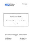
MAIN FEATURES
Vl
• 500 Mllz ami 1 Gllz
Bmulwidtb
~
~
>
• 2 G5/s mul 4 GS/ s SingleSimi Sample Rate
• 8 Milliou Poiuts tif
Acquisiliou MemmJ•
• 4 ms Maximum Sample
RClle Wilulmt•
• 96 MHz Pou•erPC
Microprocessor
• 8 to 64 MB System RAM
• 9" Color Display ll'ilb 8
Trttces
U 5 vs
li 1 f.'S
28.8~V
2e.a~v
2 5 vs 8.58 v 3 5 vs 28.8~ 4 ~ ~s ~~~~v
1 f.'S 2a.e~v t 58vV 15.2 •
o 5 MHz 18.6
ITJ
• Analyze your signal to get answers
quickly and more accurately with a
powerful processing system and
math packages.
9"
COLOR DISPlAY
LeCroy provides a vety large,
sharp oscilloscope screen that is 50%
larger in total viewing area than a 7"
screen.
• Analog Persistence
• Full Screeu Gritl
Digital oscilloscopes from LeCroy are
designed to save engineers valuable
time in troubleshooting and problemsolving.
Each oscilloscope is an integrated
and powertul system providing the
(~tpabili ty to:
• Capture the key events with high
resolution for longer time intervals
• View data like never before, giving
you more information more quickly,
with a large, color CRT and
advanced display techniques
Its powerful features include Analog
Persistence, Color-Graded Persistence,
Full Screen mode, Opaque or
Transparent display, color as.~ociation,
and personal color schemes. These
provide the user with outstanding benefits that accelerate visual processing
and effective communication of onscreen information.
HIGH-SPEED ACQUISffiON
The design and debug of fast digital
systems and the need to capture fast
transient signals require high-speed signal capture. The LC574A four-chatmel,
1 GS/s, 1 GHz bandwidth DSO operates at a 4 GS/s sample rate for singlechannel inputs. The high sample rate,
bandwidth and the 1 GHz trigger bandwidth provide a tlexible solution for
capruring and viewing fast risetime signals.
http:/jwww.lecroy.com
VISIT
US
AT
0 UR W EB
elf,
u
...........
:.IUI'I-'tu
Vl
">
~
LARGE SAMPLE RATE
WINDOW
Having :1 high ,;ample t<tte in .1 DSO t.s
only rhe fir~t stl'p to preservmg dau
integrity The tmw windo\\' mer "l11d1
this sample rate is .wailable is ;tlso of
critical impo11ance. Long acqtll,itton
memory maintJins the oscilloscope's
highest sample rate for large time windows allowing the u"~·r to s;tmple lnng
signab with high horizontal resolution.
(I'J
tTJ
==
tTJ
~
\J)
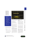
With up to H mtllton points of ,tcqutsttion memory. the ma}..imum s:nnple
rate of the LC'i74AL of ·+ GS s (2 CS '
in LC334AL and LC'i3"1AU is maintained for a ume windo-..v of .2 ms
(4 ms in LC33"1AL and LC'i.:\o!Al). This
sample rate window enables the user
to record long signals with htgh resolution.
OPTIMUM PERFORMANCE
SMARTMemur~
is .1 total metllUt)
management system that d~ namll\tlly
allocaws resources of mKroproce.ssor
power. acquisition memory and processing RAM. The intelligelll man:.tgement provided by SMARTMemory
guamntees optimal usage of oscilloscope resources
S ITE
15
The 96 MHz PowerPC nucroprocessor
.n till' lll•;ut of the~e DSOs drives the
sy!'tem to produce results fast, providmg t:tpid waveform update and super
panel rt•sponsiveness.
QUICK DIAGNOSES
Capturing and viewing waveforms are
fundamental to an oscilloscope.
Prtxlucttvtry improvements are accessible b) using butlt-in math functions to
.tssist troubleshooting and diagnoses of
circun problems.
The signal analysis capability of these
DSOs is enhanced by advanced wavefonn math, spectntm analysis, and
waveform parameter analysis. This
analysb c.-apability greatly increases the
speed with which circuit problems are
de:trlv identified and solved.
ANALOG PERSISTENCE
i\t a push of the green button, the user
ca n switch berwcen :111 analog style
view and a digital view of signals on
these oscilloscopes.
The depth of signal information can be
explored along the third dimension of
the wavl'lillm display to give the user a
complete ricrure of wavefom1 activity.
Unlike an analog oscilloscope, all signal dat;l is captured and available in
memory for analysis and measurements. Analog Persistence gives the
user the best of both the analog and
digital worlcb of oscilloscopes.
FULL SCREEN GRID
LeCroy DSOs not only have a vcty
large 'F screen but also provide a display mock with an extra-large grid, up
to I ~OO'o larger than common grid
areas. In Full Screen mode, all of the
screen area is used to display signals.
TI1is prcwides a magnificent view of up
ro 8 waveform.~: sign;~[ details are seen
mort• d early and with greater ease.
8-TRACE DISPlAY
An 8-trace dL~play with any combination of math functions, zoom::., reference memories. or channels is a ManJard li:ature tn the l.C senes.
Maximum Sample Rate and Acquisition Memories
-.
Maxllllum Sample Rate
Channel Use
LC334A
LC534A
All
Peak Detect OFf
SOOMSis
Paired
Peek Detect OFF
Paired+=
Peak Detect
All
Peak Detect ON
:! '-">74A"
Memory per Channel
J
tc574A •
'
1 GSIS
1 GSis
LC334A
LC374A'
LC534A
LC574A
LC334AM
LC534AM
LC574AM
LC334AL
LC534AL
LC574AL
100k
SOOk
2M
All
4M
CH2&CH3
8M
One
1 GS/s
2GSis
2 GSis
:1
250k
2GSis
2 GSis"
4 GSis
']
500 k
100 MS/s data +
400 MS/s peaks
so k data+
so k peaks
~
l
1M
.~r
2M
Active
Channels
'
-
250 k data+ 1M data+
250 k peaks 1M peaks
All
*No external adapter
**On CH2
Oct<tl grid display is available in normal
and FuU Screen display modes, with
and without parameters displayed.
EAsY DOCUMENTATION
All waveform data and re!>ults of analysis can be quickly saved to t1oppy disk,
memory card, ATA flash card, or a
removable hard disk. This provides an
efficient way to archive information
and facilitates easy documentation of
results.
An internal graplucs printer (standard
in "L" models) outputs screen dumps in
seconds providing the user with an
inlmediate and clear record of signal
activity.
SIGNAL CAPIURE
ACQUISffiON SYSTEM
LC334A/LC374A Bandwidth (-3 dB):
@ 50 .Q: DC to 500 MHz
LC534AILC574A Bandwidth (-3 dB):
@ 50 .Q: DC to 1 GHz
Sensitivity LC334A:
2 mV/ div to 'i Vldiv, 'iO .Q, fully
variable.
2 mV!div to 'i V/ div I M.Q, fully
variable.
Sensitivity LC374A/LC534A/LC574A:
2 mV/ div to I Vldiv, 50 .Q, fully
variable.
2 mV/div to 10 V/div, I M.Q, fully
variable.
Scale factors: A wide choice of probe
attenuation factors are selectable
O~etRangeLC334A:
2.00- 9.99 mV/ div:
10.0- 199 mV/div:
0.2- 5.0 V/ div:
±120 mV
±1.2 V
±24 V
O~etRangc
LC374A/LC5yVV1C574A:
2.00- 4.99 mV/ div: ±400 mV
5.00- 99 mV!div:
±I V
0.1-l.OV/ chv
±IOV
1.0- 10 V/ div:
±100 V
(I M.Q only)
Bandwidth (-3 dB): @ 1 M.Q: DC to
500 MHz typical at probe tip with
optional 1 GHz FET probe for LC334A
and with PP005 standard with LC374A,
LC534A and LC574A.
No. of Channels: 4
No. of Digitizers: 4
Max. Sample Rate Window:
4 rns @ 2 GS/s in s ingle-shot mode;
LC334AL, LC534AL.
2 rns @ 4 GS/s; LC574AL.
High P<'rJiwnwlll; e sif.llllll condiiiCIIIIIIf.l
di!VICf!S presert~' Si[.ll lllf t;(J!l/t!l/1
16
I I. ,
-
•
----
~
~
Measurements
~
~
~
~
CURSOR MEAsUREMENTS
Relative Time: A pair of arrow cursors measure time differences and voltage difterences relative to each other.
Relative Voltage: A pair of line cursors measure voltage differences.
Absolute Time: A cross-hair marker measures time relative to the trigger and voltage with respect to ground.
Absolute Voltage: A reff'rence bar measures voltage with respect to ground.
AuroMATED MEAsUREMENTs
>
...........
~
-
........
~
A wide range of pulse parameter measurements are available. These are categorized for ease of use. 111e categories
include Pulse, Horizontal, and Vertical parameters. Basic statiStical measurements (average, highest, l owe~t. and standard deviation), can be made on these parameter values in order to understand their distribution. Pass/Fail 'lb;ting
and Waveform Umit testing using masks can be perfonned. Test conditions can be expressed as either wavefonn
parameter limits, waveform shape limits (mask) o r .a combination of both. Any failure can c-.wse preprogrammed
actions such as Hardcopy, Save, GPffi service request, logic pulse out, audible beep, or any comhination of the
above.
>
...........
V\
~
~
.
>
...........
DC Accuracy: Typical l o/o
Vertical Resolution: 8 hits
Bandwidth limiter LC334A: 30 MHz
Bandwidth limiter LC374A!LC534AI
LC574A: 25 MHz, 200 MHz
Input Coupling: AC, DC, GND
Peak detect: At 400 MS/s, peak detect
can capture high-speed e vents down to
1 ns, while simultaneously captu ring
normally sampled data.
Sequence: Stores multiple events each of them time stamped - in segmented acq uisitio n memo ries.
Dead Time between segments:
Typically <30 ps, max. 50 ps
Input Impedance: 10 MQ// 15 pF fo r
LC334A (system capacita nce using
PPOOS), 10 Mn//11 p F for LC374A/
LC5.;4A/LC'i74A (syste m ca pacitance
using PPOO'il or 'iO Q ±1%.
TIMEBASE SYSTEM
Max Input:
Time/ Div Range: 1 ns/div to 1,000
s/div.
50 !l: ±5 V DC (')()() mW) or 5 V RMS
J M!l on I.C.3.34A: 250 V
1 Mil on LC.374A/tC534NLC574A:
400 V (DC + peak AC ~ 1 0 kHz)
SMARTMemory: This to tal memory
management syMcm dynamically manages acqltlsition memory to guarantee
that signab arc always sampled at the
h1ghcst possihl<: sample rate and that
system RAM and rmcroprocessor
rcsouro:~ arc always optimally
employed
Acquisition Modes
Random Interleaved Sampling (RIS):
For rcpcuuw srgnals from 1 ns/div to
S IJS/div (2 ps/drv for LC374A and
LC'l7'tAl
Single shot: For tmnsient and repetitive signals from 10 ns/div (1 ns/cliv fo r
LC91iA and LC5711A) with all channels
act1vc
~
~ 10
ADDIDONAL INFORMATION
(I'J
INTERFACING
::e
~
t'rl
Cll
GPm Port: Contigurahk· .1s t.llkL·r 1!~
tener for computer control and f;tsl
data tr.msfer. up to .300 kbytt'S sec.
Command Langua~-te t·omplies with
requirements of 1EEJ:>t!:l8.2.
ppm
Centronics Port: Hardcopy parallel
intetfacc 1s :-.tandard.
MH z (20-100
MHz for LC574A and LC37'lA) on EA'T
mput with ECL, TIL or zero cro~ing
PC Card (PCMCIA 1/D/ill) Ports : For
memo!) cards. ATA (.'0111JXllihlL" lhsh
cards ~md rt'I110\ •lhll' h.ml Lhsks
opuonal.
Model
LC334A/LC374A LC534A
LC574A
LC534AM
LC574AM
LC334AM
-.
I
LC534AL
.I
LC574AL
LC334AL
I
I
t'rl
115.2 Kb/ s for t·omputc:r· tcnninal nmtrol or printer/ plotter connecuon.
Roll Mode: Ranges 500 ms to 1,000
s/div. For >50 kpoints: 10 s to 1,000
s/div.
~ 1 00
>
RS-232-C Port: Asynchronous up to
Interpolator resolution: lO ps
External Oock:
~
External Reference: Opt1tm:tl 10 Mllz
rear-pane l input.
Remote Control: Poss1hil' h) GPIB
and RS-2.32-C for all tront-pand wn
trois, as well as all intemal funt·tJons
Timebases: Main and up to 4 Zoom
Traces
Clock Accuracy:
V\
........
levels. Optional SO MHz to 'iOO 1\11-lz
rear-pane l fixed frequency d<x-k mput.
I
I
Segments
500
2,000 . ..,.
2,000
Num/Jer of segm ents at•allable
http:jjwww.Jecroy.com VI S IT
U S AT 0 U R W E B S I TE
17
-
- --- - - - - - - - -
Signal Analysis
SIGNAL ANALYSIS
A comprehensive and e:tsy-to-u:-.e set of diagnostic tools are available. Calculations are performed rapidly, :md
resuhs can be presented on-screen or stored to disk.
Rapid Processing System•
Microprocessor: 96 MHz PowerPC 603e.
System RAM: 8 ro 61 Mbyres.
Video Memory: 1 Mbyte.
cache Metnory: 32 khyte.
Persistence Data Map Memory: 16 bit:-; per displ:tyed pb:el (64 k levels).
WAVEFORM PROCESSING
Cp to fou r pr<..'Cessing fimctions may be performed sitnultancous\y. Stan<.W'rd functions available are: A4d.
Subll~lct, i\Jultiply, Divide, Negate, Idt:ntity-, Summation Averaging and Sine x/x. TI1e source information for a
math function tr<tce can he data from an acquisition channel o r from another mad1 function trace. This allows
display of traces which "daby chain'' nutth functions.
Average: Up to 10' averages are possible.
Extrema: R<x>f, Floor, or Envdope values from 1 to 10" sweeps.
ERES: Stx low-p~tss digital tllters provide up to 11-hit vertical resolution. Sampled data is always available, t:VCn
when a tmce is turned off.
FFf: Specnum Analysis with five ·windowing functions and Fr'T avc;:mging.
Statistical Diagnostics•: The Parameter Analysis package permits in-depth diagnostics on \vavefonn parame..
ters. Live histogramming of <Ul}' wan~form parameter measurement is possible and the hi:-;togram can be
autoscakd to display the o..:nter and width of the distribution.
Any of the <\bon: processes can be invoked without losing the data.
•IJi:-.togramming and Trending are part of the Parameter Analysi~ Package.
INTERNAL MEMORY
Waveform Memory: Op to Ii.mr 16-bit Memories (Ml, M2, M3, M4>. whose length con-esponds to the length
of th<..' channel acquisition memory.
·
Zoom & Math Memory: Up to four 16-bit Wavefmm Processing Memories (A, B. C, D), whose length con~
:-ponds to the length of the channel acquisition memoty.
Setup Memory: Four non-volatik· memories. TI1e floppy disk or optional memory cards. Flash card or removable hard disks can also be used f(.)t' high-capacity waveform and setup storage.
Floppy Disk: lligh-dcnsit) j.')'' floppy
thsk dri1 L' <I)()~ l(mnat) i~ st,tndard.
VGA Compatible Display: 1'i-pin
I )-t) I)L' \'(;A compatible connector for
t''tvrn:tl color dispht).
Hardcopy: Scrt•en clumps arc actinttcd
h) .1 fmnt-p:u>t·l huttnn ur 1 ia remote
coni rol. 1'1 1-'F ~md 131111' formats are
tuil:thlt· for importing to 'k·sktop publishing programs. The following printl'l's ami plotters c.tn he u~ccl to make
11.1 rdn >ptes:
B/W: Ill' l.:tSL'I:Iet. Ill' lksk.Jet 'i00.
Fpson FX.
Color: HP Desk.Jet 550C, F.p~on Stylus.
Canon BJC. An optional. intcmal, highresolution gt:tphics printer is also available for screen dumps; a su·ipch:.trt output format with 2 meters per division is
also possihle.
Output Formats: ASCIJ wa1cfonn nutput is available in seconds. compatihiL'
with spreadsheets, MATLAB, MathC:td.
Binaty output is also available .
GENERAL
Auto-calibJ:ttion ensures specified DC
and timing accuracy.
Ten1perature: so to ·!0°C ( tl" to
10·1°1') rated 0° ro 'i0°C (:\2° to J22°Fl
operating.
Hunlidity: H(Y)I,, f( >r tL'IlliK't:tturcs up to
:H°C decr<..'asing linv:trly to ::;m., rdatii'L'
hum id ity at t0°C.
Altitude: l ip to 2000111 <opcr;lting>.
J0°C Ill:! X.
Power: W-1.)2 V AC. JH0-2'i0 \' AC.
l'i-66 liz. 100 \'1/.
Battery Backup: Front-panel
maint:.tined f(>r two yc~trs .
~etting.\
Dimensions:
(HWD)IO.'J" x l'i.(J'i" x 17.8">" (26-l nun
X 397 Ill ill X tj'ij Ill Ill)
Weight: 20 kg ( 11 lbs) net, 28 kg (61.6
lhs) shirpmg.
Warr.mty:
Tim:~.:
~
UJ
UJ
~
Waveform Style: Dot Join with optional sample point highhght or Dots only.
>
years
CE Approval: l:!\1C: Cont<.mns to
EN')OOHI I and E!'<'i00H2- l.
ULand cUL approved: UL standard:
LL 31 J 1-1. d L C.1nathan Standard
CSA-C22 2 No. I 010. 1-92.
ha~ heen
comply w1th EN61010-l
ln.\tallatu m Catq~ory (Over-voltage
Cate~o1yl II. Pollution Degree 2.
Safety: 'l11e os<:illoscope
de~1~ned to
Persistence Modes: Color-graded persiste nce and Analog Persistence, infinite
or variable w1th decay over time. In
color-graded persiMence, a <.:olor spectrum from red through violet is used to
map signal intens ity. With Analog
Persi~tence , the brightness level of a
single color denotes signal intensity.
Each tm<.:e's persistence data is stored
in 64 k levels. Analog Persistence is
only available in fou r channel mode on
LC334A mcxlels.
Trace Display: Opaque or transparent
mode, with overlap management.
SIGNAL VIEWING
Type: Color 1)" lbster Scan CRT,
0. 26 111111 dot p1tcil
Number of Traces: 8 (any mix of
channels, memories or Math functions ).
Resolution: (Y!O x ·180 points.
Display J\J·ca: 170 111111 x 12'> mm ')(y•' gn:-.ller than th,l! of a T d1splay.
Controb: Hear pan..:l preS<:ts for posiuon, bnglunes.~ and contrast. Menu
rontrob lCJr brightnc~s and color selec-
Real-time Qock: Date, hours, minutes,
seconds.
External Monitor: Rea r-panel IS-pin
-.cx-ket for VGA compatible monitor.
tion.
Ve rtical Zoom: Up to 5x vertical expansion (50x with averaging, up to
40 pV/ div sensitivity).
Grid Styk-s: Singll', Dual, Quad. Octal,
XY, Smgk+ >.."1, Dual+ XY, and Full
ScrtXn an c:nlarged view of each grid
style.
Horizontal Zoom:
LC334A/LC534A: Waveforms c..tn be
expanded to give 2-2.'> pomts/divis1on.
UJ
-.....~
~
>
..........
Precision sampli11g del'iCI!:i 111tlllllllill '(~
nat IIII£'RI"il)' ill the tf~f!,ilalworlt!
Vl
UJ
~
>
..........
This allows zoom factors up to
l OO,OOOx for the 'M' Jll<Xlt:b .md up to
400,000x for the ·L' mock· Is "hl'n channels are combined.
Vl
........
~
>
LC374AILC574A: \V;~\ dorms c1n lx·
expantkd to gi\ ~· 0 t-0.-; po1111..; per
chd.s1<>n. Zoom L1ctor.~ up tn .!.tllXl.\lOth
\\.ith .IIi dunnvb comhinl·d on tiK'
\JJ
LC'i7 <1AL.
tTl
tTl
~
~
'J)
TRIGGERING SYSTEM
Mode!>: :-.onnal. '\uto. Single. ,md
Sources: Clll. Cll2. Cll5. Cll1. L11w,
EXT. P ...'T 10. Slope. l.l'' d .111d
Couplmg :1re LII1KJllt' to I!:Il'h 'ourct·
Slope: Po:;it1vc. 'Jegatl\'t'.
I
Coupling: AC, DC, Ill'. I.FRI\).
Model
System RAM
LC334A/LC374A I l.C534A
I LC574A
8 Mbytes
-L6334AM-- · -cc534AM 1 LC574AM 0M,.;byt:......e......
s""'-"'<~t.,.
'Lc334AL
..- lc534AL
- r------ns Mbytes
- · LC574AL [M Mbytes
r
Post-trigger delay: o to lll.tl\Xl di' tsions (aclju,I:Ihk in 0. 1 di\ 111' tt' mentsl.
Maximum Horizontal Zoom Factors
Holdoff by tiJnc: 10 n, to 20 '
I ~.·
Mode~.
r-LC334A"I LC534A
;LC334AM"[lc534AM., LC374AILC574A
LC334AL :1 Lcs34A.I- Tcs74AM
[ LC574AL
I
Holdoffby events: 0 to
Zoom Factors
4,000x
II:
l lll(i,
20,000x
100,000x
i;,
400,000x
C··~
http:/jwww.lecroy.com
IIFRr~l
Pre-trigger r<.><:ording: 0 to I 00% ot
full scale (adju,t.thk· in I"" 111trt'lllt'i1l'l
,;.;..;
.<~.-·".
..........
Stop.
System Memory Configurations
- ......,.; ............... o·o~
~
Graticules: Internally generated; separate intensity control for grid~ and
waveforms. Selectable blending of grid
with displayed traces.
l)l),l)<)'),')<l')
Internal Trigger Range: t-; tli'
-~
V 1 S 1T
US
AT
0 UR
W EB
S ITE
19
EXT Trigger Max Input LC334A:
LOMQ l'ipF
{,;ystem capacitann: using PPOOS):
'iO V (DC+ peak AC :o;lOkHz)
'iOn ±1<Jo: ±'i V DC (500 mW) or 5 V
Hl\IS.
EXT Trigger Max Input
LC374A!LC534A!LC57~
10 Mil. l1pF
(wstcm tJpacitance using PPOOS)
-!00 V (DC + peak AC :o;JQ kHz)
'iOn ±1%: ±5 V DC (500 mW) or 5 V
tuvt~.
EXT Trigger Range: ±0.'> V ( ±5 V with
Ext/10).
Trigger Tinling: Trigger Dare and
Tune are listed in the Memory Status
\knu.
Trig,_~er
Comparator: Qp[lonal ECL
n·.ll'-panl'l output Alternatively, the callbr..llor output can prov1dc a uigger
output or a Pass/Fatl lest output.
SMART TRIGGER TYPES
Pattern: Trigger o n the logic combination of 'i inputs - CH 1, CH2, CH3, CH4,
and E.,"\.'T Trigger. where each source
can he defint:d as High, Low or Don't
Care Tht• Tngger t·an he detinet! as the
bq~inning or end of the specified pattern.
Signal or Pattern Width: Ttigger on
width between two limits selectable
from <2.5 ns to 20 s. Will typically trigger on glitches 1 ns wide.
Signal or Pattern Interval: Trigger on
tnt en ;tl bt·lw<xn two limits selectable
from 10 ns 10 20 s.
Dropout: Trigger if the input signal
drops our for longer than a time-out
from 2'i ns 10 20 s.
State/Edge Qualified: Trigger on any
.~ource only if a gtven state (or transi-
Analog Pers£~1er1ce gives the user em analoR style uiew ofS1'p,11al.~ 011 a dll~lftll os~ llloscvfJ<!
tion) has occurred on another source.
The delay between these events can be
defined as a number of events on the
trigger channel or as a time inte1val.
1V: Allows selection of l:x>d1 line (up to
1500) and field number (up to 8) for
PAL (SECAM), NTSC or nonstandard
video.
Exclusion Trigger: Trigger on intermittent faults by specifying the normal
width or period of a signal. 'The oscilloscope will trigger only on aberrations
which are shutter or longer than normal.
AurosETIJP
Pressing Autosetup sets timebase, trigger and sensitivity to display a wide
range of repetitive signals, (Frequency
above 50 Hz; Duty Cycle greater than
O.lo/o).
Autosetup Tune: Approximately
2
~econds.
Vertical Find: Automatically set~ sensitivity and ofT~et for selected channel.
PROBES
O ne PPOO'i probe is supplied per channel. DC to 500 MHZ typical (350 MHz
typical for LC3YIA) at probe tip, 500 V
max.
Probe calibration: Max J V into
I Mn. 'iOO mY 111to ')() !2, lre<.juency
and amplitude progmmn1.1hle, pulse or
square wave selectable, rise and
falltime 1 ns typical. Ahcmatively, the
calibmror output ca n provide a trigger
output or a Pass/Fail lest output.
~
~
LC33W374Af534A/574A - ORDERING INFORMATION
~
\.,N
Product Code
LC334A
LC334AM
LC334AL
Digital Oscilloscopes:
500 MHz, 500 MS/s, 100 kpts./ch, 4 channel Color DSO
500 MHz, 500 MS/s, 500 kpts./ch, 4 channel Color DSO
500 MHz, 500 MS/s, 2 Mpts./ch, 4 channel Color DSO
~
>
..........
LC374A
500 MHz, 1 GS/s, 100 kpts./ch, 4 channel Color DSO
1 GHz, 500 MS/s, 100 kpts./ch, 4 channel Color DSO
1 GHz, 500 MS/s, 500 kpts./ch, 4 channel Color DSO
1 GHz, 500 MS/s, 2 Mpts./ch, 4 channel Color DSO
LC534A
LC534AM
LC534AL
1 Gflz, 1 GS/s, 100 kpts./ch, 4 channel Color DSO
1 GHz, 1 GS/s, 500 kpts./ch, 4 channel Color DSO
1 GHz, 1 GS/s, 2 Mpts./ch, 4 channel Color DSO
LCS74A*
LC574AM*
LCS74AL•
Included with Standard Configuration:
10:1 10 Mil Passive Probe (1 per channel)
Operator's Manual
Remote Control Manual
Hands On Guide
Advanced Waveform Math Package
Spectrum Analysis Package
Floppy Disk Drive
Perfonnance Certificate
Three-Year Warranty
\.,N
'
APOll
AP020
AP021
APS4701A**
AP1143A**
PPo62
PP090
Software Options:
Parameter Analysis Package (includes Histogramming and Trending)
Disk Drive Measurements
Supplementmy Disk Drive Measurements
Optical Recording Measurements
Disk Drive Failure Analysis
WP03
DDM
PRML
ORM
DDFA
"'
~
\
PPOOS
1. ,
LCXXX-OM
LCXXX-RCM
LCXXX-HG
WPOl
WP02
FOOl
Probes & Accessories:
Current Probe 150 A
1 GHz 10:1 FET Probe
800 MHz 5:1 FET Probe
2.5 GHz 0.6pF Active Probe
Probe Offset and Power Module
1 GH7., 10:1, 500 Q Passive Probe
ProBus 75 Q to 50 Q Adapter
[
>
..........
VI
\.,N
~
>
..........
VI
"'>
~
\JJ
~
~
~
(J'J
Hardware Options:
Memory Card Reader and 512k SRAM Card
PCMClA Type lli Slot for Hard Drives and ATA Flash Cards
PCMClA Hard Disk 170 Mbyte (requires HDOl option)
4MB ATA Flash Card (requires HDOl option)
lntemal Graphics Printer
500 MHz Ext Clock, 10 MHz Ref Input, Trigger Comparator Output
64 Mbyte System Memory
MCOl/04
HDOl
HD02
4MBFC
e>wr··
CKTRIG
64MBSM***
Manuals:
LCXXX-SM
Service Manual for LCXXXA
Warranty & Calibration:
LCXXX-CCMlL
LCXXX-CCNIST
US Military Standard
US NIST Standard
• Includes Internal Graphics Printer and Parameter Analysis Package
•• NormaUy ordered together
••• Included with LC574AL
http:/jwww.Jecroy.com
V IS IT
US
AT
0 UR W EB
S ITE
21:-q


![Manual Audition 4 [By Dr.J.]](http://vs1.manualzilla.com/store/data/005935757_1-4addafd8884e379cc6f9c4cc1fe5fdba-150x150.png)