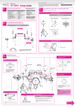
1
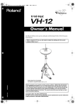
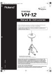
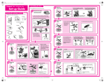
Owner’s Manual
The VH-12 V-Hi-Hat is to be used in combination with the Roland TD-20 or TD-12 Percussion
Sound Module.
When using the VH-12, you will need to make the settings for the sound
module. Refer to p. 8
fig.Structure
* Hi-hat stand is not included.
For details on compatible stands, refer to p. 10.
03458434
’05-10-6N
202
Copyright © 2004 ROLAND CORPORATION
All rights reserved. No part of this publication may be reproduced in any form without the
written permission of ROLAND CORPORATION.
USING THE UNIT SAFELY
Used for instructions intended to alert
the user to the risk of death or severe
injury should the unit be used
improperly.
Used for instructions intended to alert
the user to the risk of injury or material
damage should the unit be used
improperly.
* Material damage refers
other adverse effects
respect to the home
furnishings, as well
animals or pets.
001
•
to damage or
caused with
and all its
to domestic
Before using this unit, make sure to read the
instructions below, and the Owner’s Manual.
The
013
•
................................................................................................
002a
•
Do not open or perform any internal modifications
on the unit.
................................................................................................
003
•
Do not attempt to repair the unit, or replace parts
within it (except when this manual provides
specific instructions directing you to do so). Refer
all servicing to your retailer, the nearest Roland
Service Center, or an authorized Roland
distributor, as listed on the “Information” page.
................................................................................................
014
•
104
•
•
................................................................................................
• Subject to temperature extremes (e.g., direct
sunlight in an enclosed vehicle, near a heating
duct, on top of heat-generating equipment); or
are
• Damp (e.g., baths, washrooms, on wet floors); or
are
• Humid; or are
• Exposed to rain; or are
• Dusty; or are
• Subject to high levels of vibration.
106
Make sure you always have the unit placed so it is
level and sure to remain stable. Never place it on
stands that could wobble, or on inclined surfaces.
................................................................................................
011
•
Do not allow any objects (e.g., flammable material,
coins, pins); or liquids of any kind (water, soft
drinks, etc.) to penetrate the unit.
................................................................................................
2
Try to prevent cords and cables from becoming
entangled. Also, all cords and cables should be
placed so they are out of the reach of children.
Never use or store the unit in places that are:
•
Never climb on top of, nor place heavy objects on
the unit.
................................................................................................
115b(modified)
•
Install the unit only on the hi-hat stand which
satisfies the specifications described on p. 10.
Remove only the specified screws during the
installation.
................................................................................................
118
•
................................................................................................
007
Protect the unit from strong impact.
(Do not drop it!)
................................................................................................
................................................................................................
004
•
In households with small children, an adult should
provide supervision until the child is capable of
following all the rules essential for the safe
operation of the unit.
Should you remove clutch/clamp bolts, make sure
to put them in a safe place out of children’s reach,
so there is no chance of them being swallowed
accidentally.
................................................................................................
•
Be careful not to allow your fingers or hands to be
caught between the top and bottom hi-hat.
................................................................................................
VH-12_e 3 ページ 2005年10月5日 水曜日 午前10時26分
IMPORTANT NOTES
291a
In addition to the items listed under “USING THE UNIT SAFELY” on page 2, please read and observe the
following:
558d
Placement
•
354a
•
Do not expose the unit to direct sunlight, place it near
devices that radiate heat, leave it inside an enclosed
vehicle, or otherwise subject it to temperature extremes.
Excessive heat can deform or discolor the unit.
559a
•
355b
•
356
•
When moved from one location to another where the
temperature and/or humidity is very different, water
droplets (condensation) may form inside the unit. Damage
or malfunction may result if you attempt to use the unit in
this condition. Therefore, before using the unit, you must
allow it to stand for several hours, until the condensation
has completely evaporated.
Maintenance
401a
•
402
•
add
•
add
Do not allow rubber, vinyl, or similar materials to remain
on the unit for long periods of time. Such objects can
discolor or otherwise harmfully affect the finish.
For everyday cleaning wipe the unit with a soft, dry cloth
or one that has been slightly dampened with water. To
remove stubborn dirt, use a cloth impregnated with a
mild, non-abrasive detergent. Afterwards, be sure to wipe
the unit thoroughly with a soft, dry cloth.
This instrument is designed to minimize the extraneous
sounds produced when it’s played. However, since sound
vibrations can be transmitted through floors and walls to a
greater degree than expected, take care not to allow these
sounds to become a nuisance to neighbors, especially
when performing at night and when using headphones.
•
add
•
When you need to transport the unit, package it in the box
(including padding) that it came in, if possible. Otherwise,
you will need to use equivalent packaging materials.
The hi-hat stand is supported by means of a tripod. When
installing the hi-hat, make sure the legs of the tripod are
opened wide enough to keep the equipment from falling
over.
The hi-hat’s rubber surface may turn white, but this has
no effect on the hi-hat’s function.
The section indicated by the arrows in the figure below
contains high-precision sensors. Take care not to subject
this to excessive shock, and do not allow any foreign
objects to enter the gap.
Top Hi-Hat
fig.Top2
Never use benzine, thinners, alcohol or solvents of any
kind, to avoid the possibility of discoloration and/or
deformation.
Additional Precautions
553
•
556
•
Bottom Hi-Hat
Use a reasonable amount of care when using the unit’s
buttons, sliders, or other controls; and when using its jacks
and connectors. Rough handling can lead to malfunctions.
fig.Bottom2
When connecting / disconnecting all cables, grasp the
connector itself—never pull on the cable. This way you
will avoid causing shorts, or damage to the cable’s
internal elements.
558a
•
To avoid disturbing your neighbors, try to keep the unit’s
volume at reasonable levels. You may prefer to use
headphones, so you do not need to be concerned about
those around you (especially when it is late at night).
3
VH-12_e 4 ページ 2005年10月5日 水曜日 午前10時26分
Getting Started
Features
Similar Touch and Feel as with an
Acoustic Hi-Hat
Package Contents
Top Hi-Hat
fig.Top
The superior design has taken into account not only the shape
of the hi-hat, but also the bounce of the stick, and even the
movement caused by playing, making it possible to play with
the same feel as an acoustic hi-hat.
Smooth Transition Between Closed
and Open Tones
When you strike the pad while gradually opening the pedal,
the tone smoothly opens in response to how much the pedal is
opened.
Bottom Hi-Hat
fig.Bottom
Pressure Sensitive
You can alter the closed tone by continuing to press harder on
the pedal after it is closed (p. 10).
Allows Foot Splashes
fig.Accessories
You can play foot splashes by pressing the pedal and then
instantly opening it.
Special VH-12 Clutch
Quick-Open Tone Changes
Get realistic tonal changes by hitting the closed hi-hat and
immediately opening it.
* The clutch included with the hihat stand will not be used.
Clamp
Natural-Feeling Action
The top hi-hat weight, gap between the top and bottom
cymbals, and hi-hat stand tension gives the pedal action an
extremely natural feel.
Holder (3 types)
Dual Trigger Capability
Sensors in both the top and edge portion make it possible to
get different sounds by striking the bow (upper surface) and
the edge (p. 10).
Link Cable
Cable Tie
They’re Quiet!
Rubber is used on the striking surface for a damping effect.
Compatible with Commercially
Available Hi-Hat Stands (p. 10)
4
Tuning Key
VH-12_e 5 ページ 2005年10月5日 水曜日 午前10時26分
Mounting on the Hi-Hat Stand
(1) Assembling the Top Hi-Hat
* Orient the stopper so that it matches the groove in the top hihat.
fig.Top-02
* Due to the different shape, the clutch included with the hi-hat
stand cannot be used with the VH-12. Be sure to use the special
VH-12 clutch.
fig.Clutch.e
Clutch Top
Clutch Screw
Lock Nuts
Felt Washer
Clutch Bolt
4. Attach the felt washer, the two lock nuts, and
the clutch top, in that order, above the top hihat.
5. Confirm that the upper end of the screw pipe of
the stopper can be seen through the slit of the
clutch top, as shown in the figure.
Stopper
fig.Top-03.e
1. Use the tuning key included with the VH-12 to
loosen the clutch bolt, then simultaneously turn
and remove the clutch top.
fig.Clutch-2.e
The upper end of the
screw pipe of the
stopper can be seen
Clutch Top
6. Orient the clutch screw so it’s in a convenient
location, then tighten the clutch bolt with the
tuning key.
Clutch Bolt
7. Securely tighten down the felt washer and two
lock nuts.
fig.Clutch-3.e
2. Remove the two lock nuts and the felt washer.
3. Pass the screw pipe of the stopper through
from the underside of the top hi-hat.
fig.Top-01.e
Top Hi-Hat
Lock Nuts
* Looseness or play in the clutch may prevent the hi-hat from
operating properly.
5
VH-12_e 6 ページ 2005年10月5日 水曜日 午前10時26分
Mounting on the Hi-Hat Stand
(2) Assembling the Bottom Hi-Hat
At this point, position the LINK jack so it’s on the far side
of the unit, facing away from the performer.
fig.Bottom-01.e
1. Remove the clutch included with the hi-hat
stand from the cymbal rod.
LINK jack
* The clutch included with the hi-hat stand will not be used.
* It is not necessary to remove the felt (or rubber) pad on the hihat stand used for supporting the bottom cymbal.
2. Confirm that the cymbal rod is firmly secured.
For instructions on tightening the cymbal rod, refer to the
owner’s manual for your cymbal stand.
Cymbal Rod
* Looseness or play in the cymbal rod can make the top hi-hat
unstable, causing it to shake or turn, and prevent proper
functioning.
3. Place the bottom hi-hat on the hi-hat stand with
the cymbal rod passing through the bottom hihat hole.
At this point, position the “▲” mark so it’s facing the
performer.
fig.Bottom-00.e
4. Select the holder that matches the diameter of
the pipe at the top of the hi-hat stand.
There are three holders to match different pipe diameters.
L: 25.4 mm (1")
M: 22.2 mm (7/8")
S: 19.1 mm (3/4")
5. Remove the clamp bolt, then fit the holder and
the clamp so they are nested together.
fig.Bottom-02
Hi-hat stand felt
(or rubber)
cymbal pad
L
L
6
L
25.4 mm
(1")
M
M
M
22.2 mm
(7/8")
S
S
S
19.1 mm
(3/4")
VH-12_e 7 ページ 2005年10月5日 水曜日 午前10時26分
Mounting on the Hi-Hat Stand
6. Attach the clamp and holder to the pipe on the
upper part of the hi-hat stand, then slightly
tighten the assembly with the tuning key.
(3) Assembling the Overall Unit
1. Place the top hi-hat assembly on the hi-hat
stand with the cymbal rod passing through the
top hi-hat hole.
fig.Bottom-03.e
At this point, position the “Roland” logo on the farther
side, as viewed from the performer.
2. Use the link cable to connect the bottom hi-hat
and the top hi-hat LINK jacks.
Slightly tighten
3. Pull the bend of the cable softly with your
fingers.
fig.LinkCable
7. Pass the ends of the holder through the
grooves in the metal portion of the bottom hihat, then while strongly pulling the clamp
downward, secure it with the tuning key.
fig.Bottom-04.e
* Make sure that both the top hi-hat and bottom hi-hat can be
closed smoothly.
Pull down
and tighten
* Not pulling strongly enough on the clamp can make the bottom
hi-hat unstable, causing it to shake or turn, and prevent proper
functioning.
* After extended use of the hi-hat stand, the stand’s felt (or
rubber) pad on which the bottom cymbal rests becomes
compressed, which may cause the bottom hi-hat to become
unstable. If this occurs, loosen the clamp bolt and perform Step
7 again.
7
Mounting on the Hi-Hat Stand
(4) Connecting to a Sound Module
921
* To prevent malfunction and/or damage to speakers or other
devices, always turn down the volume, and turn off the power
on all devices before making any connections.
1. Connect the VH-12’s TRIGGER OUTPUT jack to
the sound module’s TRIGGER INPUT HI-HAT
jack, and the VH-12’s CONTROL OUTPUT jack
to the sound module’s HH CTRL jack.
fig.Connect.e
When using the VH-12, you will need to make the
settings for the sound module.
When Using with the TD-20
1. Loosen the clutch screw, and set the hi-hat in
the closed position.
2. Hold down the TD-20’s [KIT] button and press
the [TRIGGER] button.
The offset is adjusted automatically.
When Using with the TD-12
1. Press the TD-12’s [TRIGGER] button, then
press the [F1 (BANK)] button.
2. Press the [CURSOR] buttons to move the
cursor to the trigger type for TRIGGER INPUT 6.
3. Use the [+/-] buttons or the [VALUE] dial to
select “VH12.”
4. Press the [F3 (HI-HAT)] button.
5. Press the [CURSOR (up/down)] to move the
cursor to “Hi-Hat Type.”
* Use stereo (TRS) cables to make the connections. If monaural
cables are used, edge shots cannot be supported.
2. Secure the cables in place with the cable tie,
while leaving some slack in the cables.
fig.CableTie.e
6. Use the [+/-] buttons or the [VALUE] dial to set
the Hi-Hat Type to “VH12.”
7. Loosen the clutch screw, and set the hi-hat in
the closed position.
8. Hold down the TD-12’s [KIT] button and press
the [TRIGGER] button.
The offset is adjusted automatically.
For details, refer to the TD-12 owner’s manual.
8
Mounting on the Hi-Hat Stand
(6) Adjusting the Hi-Hat
1. Adjust the gap between the top hi-hat and
bottom hi-hat to a clearance of approximately
10 mm, then tighten the clutch screw.
fig.Gap.e
Clutch
Screw
10 mm
(3/8")
* Although the gap can be adjusted to a clearance that makes
playing the hi-hat easier, setting too narrow or wide a gap can
cause improper function of the unit and prevent the hi-hat from
sounding as you intend. Setting the gap to 10 mm provides
the most natural feel when playing the VH-12.
2. Change the spring tension by adjusting the hihat stand.
For instructions on adjusting the tension, refer to the
owner’s manual for your hi-hat stand.
* The tension may not be adjustable on some stands.
While playing, always align the marks on the top hi-hat
and bottom hi-hat (▼ and ▲) to prevent malfunction.
fig.Mark
9
VH-12_e 10 ページ 2005年10月5日 水曜日 午前10時26分
Playing Methods
Open/Closed
The hi-hat tone changes smoothly and continuously from
open to closed in response to how far the pedal is pressed.
You can also play the foot closed sound (playing the hi-hat
with the pedal completely pressed down) and foot splash
sound (playing the hi-hat with the pedal fully pressed and
then instantly opening it).
Edge Shot
This playing method involves striking the edge of the top hihat with the shoulder of the stick. When played as shown in
the figure, the “rim-side” sound of the connected trigger input
is triggered.
fig.Play-02
Pressure
When you strike the hi-hat while pressing on the pedal with
the hi-hat closed, you can then change the closed tone in
response to the pressure you place on the pedal.
Edge Sensor
Bow Shot
This playing method involves striking the middle area of the
top hi-hat. It corresponds to the sound of the “head-side” of
the connected trigger input.
fig.Play-01
Do not strike the bottom hi-hat or the underside of the
top hi-hat.
Specifications
Size:
12 inches
Trigger:
2 (Bow/Edge)
Connectors:
TRIGGER OUTPUT Jack
CONTROL OUTPUT Jack
Dimensions:
314 (W) x 314 (D) x 89 (H) mm
Weight:
1.9 kg / 4 lbs 4 oz
Options
Owner’s Manual, Clutch, Clamp,
Holder (3 types), Link Cable,
Tuning Key, Cable Tie
Compatible Stand
Diameter: 6.0–7.0 mm
(0.236"–0.276")
12-3/8 (W) x 12-3/8 (D) x 3-9/16 (H) inches
962a
* In the interest of product improvement, the specifications and/
or appearance of this unit are subject to change without prior
notice.
10
Diameter: 11.7 mm (1/2") Max.
Diameter: 25.4 mm (1")
22.2 mm (7/8")
19.1 mm (3/4")
VH-12_e 11 ページ 2005年10月5日 水曜日 午前10時26分
Troubleshooting
Hi-hat not closing
Sounds are not triggering properly
Was the unit adjusted after being
connected to the sound module?
Is the trigger type set correctly?
When using the VH-12, be sure to run the automatic offset
adjustment on your sound module (p. 8).
No sound is heard
Is the TRIGGER OUTPUT connected to
the sound module’s HH CTRL jack?
Connect the VH-12’s TRIGGER OUTPUT jack to the sound
module’s HI-HAT jack, and the CONTROL OUTPUT to the
sound module’s HH CTRL (p. 8).
The sound does not change when an
edge shot is made
Is a monaural cable being used?
When a monaural cable is used, the sound does not change
when an edge shot is made.
Use a stereo (TRS) cable.
Are you striking the area where an
edge sensor is located?
The VH-12 has an edge sensor only at the area closest to you,
at the front (p. 10).
Align the marks (▼ and ▲) on the top and bottom hi-hat, and
position the marks so they face toward the player (p. 9).
Make the trigger parameter settings for your sound module.
Are you using the special VH-12
clutch?
Clutches included with hi-hat stands are shaped differently
than the VH-12’s special clutch, so use of such other clutches
prevent the sensors within the VH-12 from functioning
properly. Be sure to use the clutch designed especially for the
VH-12.
Is the clutch correctly attached to the
top hi-hat?
Failure of the upper end of the screw pipe of the stopper to be
seen through the slit of the clutch top is one cause of double
triggering and incorrect opening and closing (p. 5,
“Assembling the Top Hi-Hat” Step 5).
Loose lock nuts can cause improper functioning (p. 5,
“Assembling the Top Hi-Hat” Step 7).
Is the bottom hi-hat attached
correctly?
After extended use of the hi-hat stand, the stand’s felt (or
rubber) pad on which the bottom cymbal rests becomes
compressed, which may cause the bottom hi-hat to become
unstable. If this occurs, loosen the clamp bolt and perform
Step 7 on p. 7 again.
Is the gap between the top and
bottom hi-hat correct?
Setting too narrow or wide a gap can cause improper function
of the unit and prevent the hi-hat from sounding as you
intend. Setting the gap to 10 mm provides the most natural
feel when playing the VH-12 (p. 9).
Is the sound module’s offset adjusted
correctly?
The offset may change somewhat as you perform. If this
occurs, run the automatic offset adjustment procedure for the
sound module once again (p. 8).
11