1
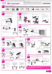
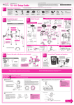
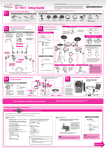
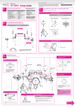
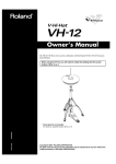
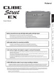
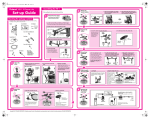
Copyright © 2009 ROLAND CORPORATION
All rights reserved. No part of this publication may be reproduced in any
form without the written permission of ROLAND CORPORATION.
Setup Guide
Check the included items
01
Before using this unit, carefully read the sections entitled: “USING THE UNIT SAFELY” and “IMPORTANT NOTES.”
These sections provide important information concerning the proper operation of the unit. Additionally, in order to
feel assured that you have gained a good grasp of every feature provided by your new unit, Owner’s manual should
be read in its entirety. The manual should be saved and kept on hand as a convenient reference.
As soon as you open the package, check to see that all items are included. If anything is missing, please contact your dealer.
Stand (MDS-4)
TD-4K parts
The parts required to
assemble the stand (MDS-4)
are listed in the MDS-4
Owner’s Manual.
Check the owner’s manual
and make sure that you
have all of the parts.
□ Hi-hat control
pedal (FD-8)
□ Kick trigger pad
(KD-8)
□ Cymbal pad for
hi-hat (CY-5)
Assemble the stand
02
Manual set
□ AC adaptor
Assembly procedure
Assemble the stand using the procedure described in the MDS-4 Owner’s
Manual.
□ V-Pad for snare
(PDX-8)
□ Cymbal pad for
crash/ride
(CY-8 x 2)
□ Pad for tom
(PD-8 x 3)
Attach the parts
03
□ Drum sound
module (TD-4)
□ Connection cable
(special for TD-4)
□ Setup Guide (this document)
□ Owner’s Manual
□ Drum key
Attach the crash cymbal (CY-8) and ride cymbal (CY-8)
Tighten the bolt with
a drum key.
Upper clutch * The parts required for mounting the cymbals and the
clutch hi-hat are included in the TD-4K attachment box.
ClutchUpper
felt (small)
Clutch felt (small)
Rotation stopper
(note orientation)
Attach the bolt so that
it is at the right when
seen by the performer.
Attach the hi-hat (CY-5)
Clutch felt (large)
Upper
clutch
Clutch
feltclutch
(large)
Lower
Lower
clutch
Clutch
felt (small)
Wing nut
Tighten the wing
nut to obtain an
appropriate amount
of sway.
Felt washer
Attach the sound module (TD-4)
Cymbal mounts
* The wingnut screws
needed for accomplishing the
installation using the sound
module mounting plate
were packed inside the bag
containing the AC adaptor.
Clutch felt (large)
Lower clutch
Pad mounts
Attach the snare (PDX-8) and
toms (PD-8)
Tighten
Tighten
Loosen
Loosen
Align with indentation
Align with indentation
Hi-hat mount
Rod
While pressing
While pressing
Pad mounts
Adjusting the tension (PDX-8)
Align with indentation
Use Drum Key
Drum Key
toUse
tighten
to tighten
While pressing
If the stand wobbles,
loosen this hand
knob and adjust the
height.
Rod
6
4
3
2
Assemble the kick (KD-8)
Assemble the hi-hat control pedal (FD-8)
Use Drum Key
to tighten
Attach the anchor bolt
(if installing on a drum mat)
* For reasons of safety, do not spread the
stand wider than 1.0 meters (40 inches).
Deeper
Slide the arm
1.0 m (40”)
Remove the stand fastening
screws from the reverse side
of the KD-8’s trigger.
Shallower
Connect the pads to the sound module
04
2. The appropriate amount of tension is one
that will provide approximately the same
striking response as on an acoustic drum.
Loosen with the drum key,
and tighten after adjusting
Spring for
the anchor bolt
RD
*
Connection procedure
Use cable ties to fasten
the cables at the circled
locations “ ” so that they
do not interfere with your
performance.
Make sure to wrap the cable
ties around the pipes.
T2
T1
TD-4
T3
CR2
* Do not connect the CR2
cable (for extension). Leave
the cap in place, and fasten
the cable so that it will not
hinder your performance.
2. Labels indicating the pad to be
connected are attached to the
cable. Connect the cable to the
OUTPUT jack of each pad as
shown in the illustration.
3. Use the drum key to adjust the tension as
needed.
* To prevent malfunction and/or damage to
speakers or other devices, always turn down
the volume, and turn off the power on all
devices before making any connections.
HH
Stereo
Headphones
AC adaptor
SNR
Power cable
1. Connect the cable to
the TD-4 as shown in
the illustration.
Pull out the stand in the
direction of the arrow, and
use the screws you removed
earlier to fasten the stand.
Connect the AC adaptor and speakers
05
CR1
5
1. Finger-tighten all six of the tuning bolts in
the sequence shown in the illustration.
Adjusting the pedal depth
Anchor bolt
Anchor bolt
1
Stereo
1/4” plug
Indicator
KIK
1/4” plug (mono)
to AC outlet
HHC
Amplified
speakers, etc.
* To prevent the inadvertent disruption of power to your unit
(should the plug be pulled out accidentally), and to avoid
applying undue stress to the AC adaptor jack, use cable ties to
fasten the cord from the AC adaptor to the stand.
* If you’re working in mono, only use the L/MONO jack.
■ When you’ve finished making connections, turn on the power as described in the TD-4 Owner’s
Manual, and verify that you can hear sound.
This completes assembly and connections.
Detailed explanation of each part
■ KD-8 (Kick)
* Use a commercially available kick pedal.
* To prevent damage to the floor or carpet and to ensure stability, we recommend that you use a drum mat (TDM series; sold separately).
01 Extend the stand and fasten it
NOTE
02 Attach the kick pedal
* Install the kick pedal securely.
When using a twin pedal
Position the two beaters equally apart from
the center of the pad as shown in the figure
at left. If one of the beater is further away
from the center than the other, the sound
from the further beater will be lower in
volume, or will not sound as desired.
Using a twin pedal will result in lower sensitivity as compared to when a single pedal
is used. Raise the sensitivity on the sound
module (TD-4) by following the instructions
given in “TD-4 Owner’s Manual.”
Position the beater so that it strikes
the center of the head, then secure the
kick pedal and KD-8 firmly in place.
* Take care not to pinch your fingers.
* The tips of the anchor bolts are sharp.
Handle with care.
* When moving the KD-8, be sure to remove
the screws and fold the stand. Transporting
the KD-8 while it remains open may subject
the stand to excessive strain and result in
damage to the stand.
Beater
1.
* Anti-skid tape is affixed to the foot plate.
When transporting the KD-8, don’t forget
to pick up the foot plate.
Remove the stand fastening screws
from the reverse side of the KD-8’s
trigger.
2.
3.
Pull out the stand in the direction
indicated by the arrow until it is fully
extended.
Using the drum key included in the
FD-8 packing carton, tighten the screws
removed in Step 1 so that the stand is
firmly secured.
Install the kick
pedal securely.
KD-8 component names
Output jack
Head
03 Adjust the height of the foot plate
This height will vary depending
on your kick pedal.
Beater
Stand
Commercially available kick pedal
Anchor bolt
When using on the drum mat
When using on
hard-surfaced flooring
* Adjust the height so that the entire pedal
comes into contact with the floor.
Foot plate
1.
Loosen the anchor bolts and temporarily remove the foot
plate.
2.
Place the KD-8 and the kick pedal on the floor. Position the
foot plate so that the anchor bolts rest on the screw holes
of the foot plate.
3.
Turn the anchor bolts to adjust the height so that the entire kick
pedal is in contact with the floor and that the KD-8 does not
wobble even when you press the pedal to make the beater strike
the pad.
When adjusting the height, lift the stand slightly while turning the
anchor bolts so that the foot plate is not fastened together with it.
4.
Screw the anchor bolts into the screw holes of the foot plate to fasten it.
If you’re using a drum mat, the KD-8 will be more stable if the pointed
portion of the anchor bolts protrudes from the foot plate. If you’re not
using a drum mat, take care not to tighten the anchor bolts too far, so
that you do not damage the floor or carpet.
Other side
Detailed explanation of each part
■■ FD-8 (Hi-hat control pedal)
■■ CY-5 (Hi-hat)
■■ CY-8 (Crash/Ride cymbal)
CY-5 component names
CY-8 component names
PD-8 component names
Wing bolt
Pad face
FD-8 component names
NOTE
Pedal plate
Anchor bolt
Pad face
Bow portion
Bow portion
Edge portion
Edge portion
Pad face
Head
* The tips of the anchor bolts are sharp.
Handle with care.
Rim
* When using on hard-surfaced flooring, the
anchor bolts may damage the floor. Do
not attach the anchor bolts.
Stand fixing
screw
Output jack
Output jack
* To adjust the travel of the pedal, loosen
the arm bolt.
Arm
■■ PD-8 (Tom)
Output jack
Control out jack
NOTE
* Continuous playing may cause dis-coloration of the pad, but this will not affect the Pad’s
function.
■■ PDX-8 (Snare)
PDX-8 component names
Head replacement procedure
Tuning bolts
Hoop
Head
sensor
Rim rubber
Head
* Be sure to adjust the head tension of the
PDX-8 before use.
* To obtain replacement heads, please contact the nearest Roland Service Center or an authorized Roland distributor, as listed in “Information.”
* Striking the head when the head tension
is loose may damage the sensor and head.
Loosen
* Do not apply excessive force to the sensor
and cushion located under the head.
Doing so can interfere with accurate
detection, and may damage it.
Wing nut
Shell
Output jack
The head is an expendable item that eventually will wear out and need to be replaced. Replace the head when the following occurs:
Slack portions remain in the head even when the head tension is properly adjusted.
NOTE
Rim sensor
1. Remove all tuning bolts and washers.
* Do not apply excessive force to the sensor and cushion located
under the head. Doing so can interfere with accurate detection,
and may damage it.
Drum key
* Due to the nature of the materials used in
the sensor of the PDX-8, changes in room
temperature may affect the sensitivity of
the sensor.
Holder
Tighten
Tuning bolts
2. Remove the hoop.
3. Remove the old head.
4. Place the new head on the shell.
* The rim rubber is one component that
eventually wears out (depending on the
number and strength of the rim shots
performed), and will require replacement.
Rim shots may not be performed correctly
when the rim rubber is worn out. If this
occurs, replace the rim rubber. Consult
Roland Service for more on replacing the
rim rubber.
5. Place the hoop on the head.
6. Attach the tuning bolts to the hoop and shell.
Hoop
Head
Rim rubber
Head
sensor
7. Adjust the head tension.
For details, refer to the explanation on the opposite side
of this leaflet.
Rim
sensor
Suitable position
for rim shots
Shell
Player
USING THE UNIT SAFELY
For China
IMPORTANT NOTES
Placement
354a
The symbol alerts the user to important instructions or
warnings.The specific meaning of the symbol is
determined by the design contained within the triangle. In
the case of the symbol at left, it is used for general
cautions, warnings, or alerts to danger.
Used for instructions intended to alert the
user to the risk of death or severe injury
should the unit be used improperly.
Used for instructions intended to alert the
user to the risk of injury or material
damage should the unit be used
improperly.
The symbol alerts the user to items that must never be
carried out (are forbidden). The specific thing that must
not be done is indicated by the design contained within
the circle. In the case of the symbol at left, it means that
the unit must never be disassembled.
* Material damage refers to damage or
other adverse effects caused with
respect to the home and all its
furnishings, as well to domestic animals
or pets.
The ● symbol alerts the user to things that must be
carried out. The specific thing that must be done is
indicated by the design contained within the circle. In the
case of the symbol at left, it means that the power-cord
plug must be unplugged from the outlet.
• Do not expose the unit to direct sunlight, place it near devices that radiate heat, leave it
inside an enclosed vehicle, or otherwise subject it to temperature extremes. Excessive
heat can deform or discolor the unit.
356
• Do not allow rubber, vinyl, or similar materials to remain on the unit for long periods of
time. Such objects can discolor or otherwise harmfully affect the finish.
add
• When setting up or storing this unit, be careful so the fingers used to grasp the stand
don’t get pinched. Also, take care that the stand does not become unbalanced and fall
over or fall against you.
Maintenance
401a
• For everyday cleaning wipe the unit with a soft, dry cloth or one that has been slightly
dampened with water. To remove stubborn dirt, use a cloth impregnated with a mild,
non-abrasive detergent. Afterwards, be sure to wipe the unit thoroughly with a soft, dry
cloth.
402
• Never use benzine, thinners, alcohol or solvents of any kind, to avoid the possibility of
discoloration and/or deformation.
002b
• Do not open or perform any internal
modifications on the unit. (The only
exception would be where this manual
provides specific instructions which
should be followed in order to put in
place user-installable options.)
104
.......................................................................................................................
• Never climb on top of, nor place heavy
objects on the unit.
.......................................................................................................................
• Always keep the following parts
including with the TD-4K and small
components that may be removed out of
the reach of small children to avoid
accidental ingestion of these parts.
• Do not attempt to repair the unit, or
replace parts within it (except when this
manual provides specific instructions
directing you to do so). Refer all servicing
to your retailer, the nearest Roland
Service Center, or an authorized Roland
distributor, as listed on the “Information.”
004
• Never install the unit in any of the
following locations.
• Subject to temperature extremes (e.g.,
direct sunlight in an enclosed vehicle,
near a heating duct, on top of heatgenerating equipment); or are
• Damp (e.g., baths, washrooms, on wet
floors); or are
• Exposed to steam or smoke; or are
• Subject to salt exposure; or are
• Humid; or are
• Exposed to rain; or are
• Dusty or sandy; or are
• Subject to high levels of vibration and
shakiness.
553
• Use a reasonable amount of care when using the unit’s buttons, sliders, or other controls;
and when using its jacks and connectors. Rough handling can lead to malfunctions.
106
003
.......................................................................................................................
Additional Precautions
• Try to prevent cords and cables from
becoming entangled. Also, all cords and
cables should be placed so they are out
of the reach of children.
558a
.......................................................................................................................
118c
• To avoid disturbing your neighbors, try to keep the unit’s volume at reasonable levels. You
may prefer to use headphones, so you do not need to be concerned about those around
you (especially when it is late at night).
558d
• This instrument is designed to minimize the extraneous sounds produced when it’s
played. However, since sound vibrations can be transmitted through floors and walls to a
greater degree than expected, take care not to allow these sounds to become a nuisance
to neighbors, especially when performing at night and when using headphones.
562
• Some connection cables contain resistors. Do not use cables that incorporate resistors for
connecting to this unit. The use of such cables can cause the sound level to be extremely
low, or impossible to hear. For information on cable specifications, contact the manufacturer of the cable.
Included Parts
Cluches/Felts/Screws/Rotation stoppers
Removable Parts
add
Nuts/ Washers/Screws/Anchor bolts/Springs
.......................................................................................................................
• Do not insert hands or fingers into the
locations indicated with arrows in the
illustrations. Otherwise, you risk getting
injured or causing damage to the product.
• The rubber portion of the striking surface is treated with a preservative to maintain its
performance. With the passage of time, this preservative may appear on the surface as a
white stain, or reveal how the pads were struck during product testing. This does not
affect the performance or functionality of the product, and you may continue using it with
confidence.
add
• Continuous playing may cause dis-coloration of the pad, but this will not affect the Pad’s
function.
962a
• In the interest of product improvement, the specifications and/or appearance of this unit
are subject to change without prior notice.
• Roland, V-Drums, and V-Compact are either registered trademarks or trademarks of
Roland Corporation in the United States and/or other countries.
.......................................................................................................................
005
• This unit should be used only with a
stand (MDS series) that is recommended
by Roland.
556
• When connecting / disconnecting all cables, grasp the connector itself—never pull on the
cable. This way you will avoid causing shorts, or damage to the cable’s internal elements.
.......................................................................................................................
.......................................................................................................................
006
• When using the unit with a stand (MDS
series) recommended by Roland, the
stand (MDS series) must be carefully
placed so it is level and sure to remain
stable. If not using a stand (MDS series),
you still need to make sure that any
location you choose for placing the unit
provides a level surface that will properly
support the unit, and keep it from
wobbling.
For EU Countries
.......................................................................................................................
011
• Do not allow any objects (e.g., flammable
material, coins, pins); or liquids of any
kind (water, soft drinks, etc.) to penetrate
the unit.
.......................................................................................................................
013
• In households with small children, an
adult should provide supervision until
the child is capable of following all the
rules essential for the safe operation of
the unit.
.......................................................................................................................
014
• Do not drop the unit.
.......................................................................................................................
For C.A. US (Proposition 65)
WARNING
This product contains chemicals known to cause cancer, birth defects and other reproductive harm, including lead.