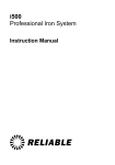
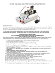
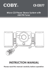
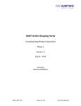
1
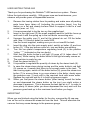
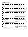
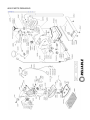
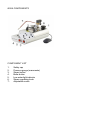
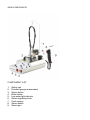
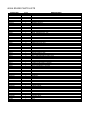
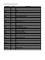
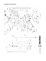
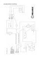
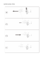
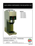
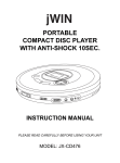
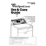
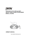
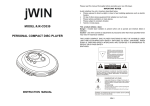
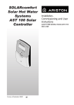
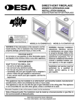
i500
Professional Iron System
i500A & i500B
Professional Steam Cleaners
Instruction Manual
USER INSTRUCTIONS i500
Thank you for purchasing the Reliable™ i500 series iron system. Please
follow the instructions carefully. With proper care and maintenance, your
steamer will provide years of dependable service.
1.
2.
3.
4.
5.
6.
7.
8.
9.
10.
11.
12.
Remove the ironing station from its packing and make sure all packing
parts have been taken off (including the protection bags). Lay the
station on a flat and steady surface fitted to support it next to a wall
socket (max. mt. 1,5).
It is recommended to lay the iron on the supplied pad.
Insert in the right seat (2) the small supplied wand to hold the hose up
and hook it with the spring up to the iron-boiler connecting wire.
Unscrew the safety cap (1) and let the internal air out. Fill the boiler
with: Max. 2,0 litres of water for model i500
Use the funnel supplied, making sure you do not overfill the tank.
Insert the plug into the main supply point; switch on boiler (4) and iron
button (3). If the two buttons come on, iron and boiler are working.
Turn the iron plate’s temperature regulating knob (6) to the position
“cotton °°°” (indicated on the iron knob).
Wait that the boiler button’s red light (4) goes off (it takes about 10
minutes). While ironing, the boiler button’s red light normally comes on.
The machine is ready for use.
Push the steam button (7).
It is possible to regulate the quantity of steam by the steam knob (8).
In case the steam stops during ironing and the water button’s red light
(5) comes on, it means that there is not enough water in the tank. To
start ironing again, switch off the boiler button (4); press the steam iron
button (7) to ensure there is no more steam in the boiler, slowly open
the pressure cap (1) and refill to the required level with warm water.
Replace the cap and wait for it to build up pressure again.
When you first press the steam button (after having turned the boiler
on and depressed the steam button on the iron) you might notice a
decrease in pressure. This is because the tank has air in it. In order to
have plenty of steam (after you have depressed the iron) wait until the
pressure goes back up to the maximum level before you begin.
IMPORTANT
When you are finished using the boiler for the day, unscrew the fill cap oneturn on the unit to release the steam/air from the tank. This will eliminate the
vacuum that may cause damage to the pressure gauge.
COMPONENTS
1.
2.
3.
4.
5.
6.
7.
8.
9.
Safety cap
Wand to hold mono-hose up
Iron power button
Boiler power button
Low water level light indicator
Temperature regulating knob
Steam button
Steam regulation knob
Manometer / pressure gauge
CAUTION
•
Do not leave the machine unattended while the plug is connected to
the socket.
•
The iron reaches very high temperatures and it keeps being very hot
even 15 minutes after it’s been switching off. Be careful not to burn
yourself.
•
For complete safety, before filling the boiler, please disconnect the
plug.
•
While using the machine, never unscrew or remove the cap while
under pressure (1). Before removing it, make sure that it does not
give off steam anymore by shutting the boiler off, and pressing the
steam iron button (7) to release all remaining steam.
•
The machine has a special heating element. Only qualified
technician should replace it.
•
The safety cap (1) must be replaced with original parts only.
TECHNICAL DATA
Adjustable iron thermostat set from 60°C to 215°C
Bimetallic safety iron thermostat with manual reset at 275°C
Full aluminium-plated heating element at 800W – 120V
Boiler power i500: 1000W
Working pressure i500: 3,5 bar
Tank nominal capacity of model i500: 2.5 litres
TROUBLESHOOTING
PROBLEM
Does
steam go
out from
the boiler?
SOLUTION
In order to solve the problem, we suggest
using the machine as usual so that the
insulating material dries up in about one
hour through the heat of the machine. In
case you still have this problem after one
working hour, please contact the service
centre.
Does the
1) While filling the tank you may have 1) The problem will go on until the excess
steam iron poured too much water into it.
water is emptied. Keep the steam button
leak steam
depressed until the water in the tank is at
mixed with
the correct level.
water?
2) The iron plate has to be hot before 2) Please check that the temperature knob
the steam passage
is on the right position: “cotton °°°)”
There is
1) The steam knob (where supplied)
1) Open the steam knob anticlockwise.
no steam
might be closed
coming out
of the
2) The iron switch might be off
2) After the iron switch comes on, wait for 4
iron?
minutes so that the iron plate gets hot.
Does the
ironing
board get
wet?
EXPLANATION
It may happen that, while filling the
tank, some water overfills the cap and
flows inside the boiler wetting the
insulating material
3) The boiler switch might be off
3) After the boiler switch comes on, wait for
10 minutes so the boiler produces steam.
4) The water might be used up.
1) The ironing board cover might not
be able to absorb the steam
completely
4) Fill it following the instructions carefully.
1) You might use a thicker cover (or two
covers) so to create a thicker surface to
absorb the steam better. In case you are
using a vacuum table, switch on the
vacuum function each time you are using
the steam
2) See # 2
2) The steam iron leaks steam mixed
with water (Check by spraying some
steam on a dry cloth)
Does the
Some dirty might have gone into the Fill the empty tank with 1 liter of water,
steam leak tank with the water and it is given off screw the cap up, shake it, unscrew the
dirty
from the iron.
cap and empty the tank. Repeat the action
water?
until the water is cleaned. We do not
recommend the use of any additive to pour
in the tank. Before ironing again spray
some steam on a cloth until clean steam
comes out.
i500 SPARE PARTS LISTS
ITEM
AC004
AST114
CD332
CD332/2
CD338/1
CD338/2
CD338/3
CD339/1
CD343/110
CD342
CD346/35
CD347
CD347/7000
CD348
CD348/1
CD349
CD350
CD351
CD353
CD356
CD360
CD361
CD363
CD365/4
CD366/6
CD367
CD368
CD368/1
CD368/2
CD369
GV028/84/110
CD374
CD376
CD377
CD378
CD378/1
CD380/110
CD382
CD384
CD458
CD458/1
CD471
CD473/1
CD476
CD477
CD490
CD492
CV103
CV114
CV177
FS002/110
FS003
FS004
FS005
FS006
FS007
NR
1
2
1
1
1
1
1
1
1
1
1
1
1
1
1
1
1
1
4
1
1
1
1
1
1
1
1
1
1
1
1
1
1
1
1
1
1
1
1
4
1
1
1
1
1
1
1
1
1
1
1
1
1
1
1
1
DESCRIPTION
BOX
FAIRLEAD FOR HEATING ELEMENT
HANDLE
HEXAGONAL HEADED SCREW FOR HANDLE
NUT FOR WAND SUPPORT
WASHER FOR STICK SUPPORT
WAND SUPPORT
TANK
COPPER HEATING ELEMENT 1000 W - 120V
TEFLON O-RING FOR THE HEATING ELEMENT
PRESSURE SWITCH WITH RESET SET 2,5 BAR
FAIRLEAD FOR CAP CONNECTION
SOLENOID VALVE FAIRLEAD
BULB THERMOSTAT 165°
SCREW FOR BULB THERMOSTAT
BIPOLAR SWITCH 16A
RED PILOT LIGHT 120/240V
CONNECTOR
4 POLE TERMINAL BOARD PA 21 TO FASTON
MONOHOSE MT. 2,2 5X10
FAIRLEAD STOP 6W-1
FAIRLEAD STOP 6N3
IRON PAD
MALE SAFETY CAP 3/8
O-RING FOR SAFETY CAP
DYN SMALL FOOT
STICK FOR MONOHOSE
SPRING
CLAMP FOR SPRING
FUNNEL DIAMETER 10 FOR ITEM 013
ADJUSTABLE SOLENOID VALVE 120V
GAUGE FOR 06-09/D
MUSHROOM-SHAPED SMALL CAP FOR IRON REST
ANTI-UNSCREWING SCREW 35x5
HOSE CLAMP 10/12
HOSE CLAMP 9/1
WIRING 120V
GLASS WOOL INSULATING
3 WAY RECEPTACLE 1/4 CONICAL 1/4 FEMALE 1/8 FEMALE
TECHNICAL DATA LABEL
SMALL TECHNICAL DATA LABEL
LOWER STAINLESS CHASSIS
FRONT STAINLESS CHASSIS
BACK STAINLESS CHASSIS
STAINLESS UPPER BODY
ANGLE CONNECTION
INSTRUCTIONS MANUAL
NUT 1/4 FOR SOLENOID VALVE 7000
IRON PACKING
KNOB 120V
PLATE
ADJUSTABLE THERMOSTAT
THERMOSTAT WITH MANUAL RESET
KORK HANDLE
BRACKET
IRON COVER
ITEM
FS009
FS011
FS012
FS012
FS014
FS015
FS016
FS017
FS018
FS019
FS020
FS021
FS022
FS023
FS024
FS025
FS026
FS027
FS028
FS030
FS031
FS032
FS033
FS035
FS037
FS038
FS039
FS041
FS057
FS058
FS060
GV025/23
GV025/27
GV025/51
GV026/7
GV026/9
GV028/30
GV028/31
GV028/36
GV028/38
GV028/39
GV028/40
GV028/45
GV028/52
GV028/6
GV669
GV671
MC016/110
RIC003
RIC003/2
NR
1
1
1
5
3
2
1
2
3
1
1
1
1
1
1
1
1
1
1
2
2
2
1
4
1
2
1
1
1
0,03
2
8
7
1
1
1
1
1
1
1
1
1
1
6
1
1
1
1
1
1
DESCRIPTION
WIRING 16AWG
INSERTION
SCREW FOR THERMOSTAT
SCREW FOR THERMOSTAT
SCREW FOR BACK HANDLE
SCREW FOR MICRO SWITCH
SCREW FOR MICRO SWITCH CASE
SCREW FOR HANDLE FIXING
SCREW FOR TERMINAL BLOCK STOP
HANDLE COVER
BACK HANDLE
BUTTON HOLDER
BUTTON CASE
UPPER IRON BUTTON
LOWER IRON BUTTON
PLAQUE FOR BRACKET
CABLE PRESS
FRONT HANDLE HOLDER
BACK HANDLE HOLDER
SCREW CAPS
BRASS WASHER
BRASS SPACER
MICRO SWITCH
UNDER SCREW
SPHERE FOR KNOB
WASHER FOR HANDLE
WASHER FOR KNOB
FAIRLEAD FOR POWER CORD
SPRING
COATED
WASHER
NUT
WASHER
COPPER PIPE
FEMALE QUICK RELEASE
QUICK RELEASE
L. JOINT
L. JOINT
ILME FEMALE SOCKET GROUP
ILME MALE SOCKET GROUP
REMOVABLE COVER
CABLE PRESS
COVER WITH ROD
SCREW
L. JOINT
BOX
INSTRUCTIONS MANUAL
POWER CORD 110V
TERMINAL BLOCK
CERAMIC TERMINAL BOARD 120V
i500 PARTS DRAWING
i500 WIRING DIAGRAM
USER INSTRUCTIONS i500A/B
Thank you for purchasing the Reliable™ i500A/B steam cleaner. Please
follow the instructions carefully. With proper care and maintenance, your
steamer will provide years of dependable service.
1. Unscrew the security cap and fill the steamer with a maximum of 2
Liters of water. If you have ordered the i500A with the nozzle and
foot pedal, screw the nozzle into the steam fitting and plug in the 4pin receptacle for the electronic foot pedal. If you have the ordered
the i500B with steam gun connect the same way using the quick
disconnect for the steam hose.
2. Plug the steam generator into the main power supply.
3. Switch on the steam generator by pressing the button "boiler" and
the steam by pressing the "steam" button.
4. Wait until the pressure reaches 3.5-bar (50 lbs). This will take
approximately 15 minutes.
5. Press the foot pedal or the (red) steam button on the steam gun and
regulate the desired steam quantity by turning the valve handle
situated behind the solenoid valve on the steam generator.
6. If you notice a decrease in steam pressure when you first use the
steamer, this is because the tank is full of air. In order to have plenty
of steam (after you have depressed the foot pedal or steam gun)
wait until the pressure goes back up to the maximum level before
you begin.
7. If during use the steam flow ceases and the low water button lights
up, it means that there's no more water in the steam generator. In
order to start steaming again, switch off the "boiler" button, slowly
unscrew the security cap, verifying before unscrewing it completely
that there is no more steam in the nozzle or steam gun. To verify
this, just press the foot pedal or the red steam button situated on the
gun. Take the plug off the steam generator and fill the steamer with
water to the required level.
IMPORTANT
When you are finished using the boiler for the day, unscrew the fill cap oneturn on the unit to release the steam/air from the tank. This will eliminate the
vacuum that may cause damage to the pressure gauge.
i500A COMPONENTS
COMPONENT LIST
1.
2.
3.
4.
5.
6.
7.
Safety cap
Pressure gauge (manometer)
Steam button
Boiler button
Low water light indicator
Steam regulating knob
Adjustable nozzle
i500B COMPONENTS
COMPONENT LIST
1.
2.
3.
4.
5.
6.
7.
8.
9.
Safety cap
Pressure gauge (manometer)
Steam button
Boiler button
Low water light indicator
Steam regulating knob
Cord support
Steam switch
Steam gun
CAUTION
•
Never leave the steamer unattended when it's plugged in. Always
pull the plug out before you fill it with water.
•
Never remove the tank locking cap while the steamer is running and
always check, before removing it, that no steam is coming out of the
gun.
•
The tank-locking cap must be replaced with original spare parts. DO
NOT TIGHTEN THE CAP TOO MUCH AS IT WILL CAUSE THE
PLASTIC TO CRACK. MAKE SURE IT IS "SNUG".
•
The use of normal tap water is recommended for the i500. In order
to clean the steam generator and remove mineral content, rinse it
internally (every 15-20 Liters of water used or every month) with tap
water.
•
The guarantee does not cover mineral damages due to not rinsing
the steam generator.
•
Service: If you need to have your i500 serviced, please contact only
authorized technical assistance centers (for further information
please call 800-268-1649 or visit our web site at
www.reliablecorporation.com).
IMPORTANT
When you are finished using the steamer for the day, unscrew the fill cap
one-turn on the unit to release the steam/air from the tank. This will eliminate
the vacuum that may cause damage to the pressure gauge.
TECHNICAL DATA
Full aluminium-plated heating element at 800W –120V
Boiler power i500: 1000W
Working pressure i500: 3,5 bar
Tank nominal capacity of model i500: 2,5 Litres
TROUBLESHOOTING
PROBLEM
Does
steam go
out from
the boiler?
Does the
nozzle or
gun leak
water
mixed with
steam?
There is
no steam
coming out
of the
nozzle or
gun?
EXPLANATION
It may happen that, while filling the
tank, some water overfills the cap
and flows inside the boiler wetting
the insulating material
SOLUTION
In order to solve the problem, we suggest
using the machine as usual so that the
insulating material dries up in about one
hour through the heat of the machine. In
case you still have this problem after one
working hour, please contact the service
centre.
1) While filling the tank you may 1) The problem will go on until the excess
have poured too much water into it. water is emptied. Keep the steam button
depressed until the water in the tank is at
the correct level.
1) The steam knob (where
supplied) might be closed
1) Open the steam knob anticlockwise.
2) The foot pedal is not plugged in
(i500B)
2) Plug the 4-pin receptacle into the boiler.
3) The boiler switch might be off
4) The water might be used up.
Does the
Some dirty might have gone into
steam leak the tank with the water and it is
dirty
given off from the iron.
water?
3) After the boiler switch comes on, wait for
10 minutes so the boiler produces steam.
4) Fill it following the instructions carefully.
Fill the empty tank with 1 liter of water,
screw the cap up, shake it, unscrew the
cap and empty the tank. Repeat the action
until the water is cleaned. We do not
recommend the use of any additive to pour
in the tank. Before ironing again spray
some steam on a cloth until clean steam
comes out.
i500A SPARE PARTS LISTS
ITEM CODE
AC003
AST100
CD332
CD332/2
CD338/1
CD338/2
CD338/3
CD339/1
CD343/110
CD342
CD346/35
CD347
CD347/7000
CD348
CD348/1
CD349
CD350
CD351
CD353
CD360
CD361
CD365/4
CD366/6
CD367
CD368
CD369
GV028/84/110
CD374
CD376
CD377
CD380/110
CD382
CD384
CD458
CD471
CD473/1
CD476
CD477
CD492
CV103
FS012
FS037
GV025/23
GV025/27
GV025/51
GV028/30
GV028/31
GV028/36
GV028/38
GV028/39
GV028/40
GV028/45
GV028/52
GV028/61
GV028/62
GV028/63
GV028/64
GV028/65
MC016/110
MC099
RIC003/2
Q.TY
1
1
1
2
1
3
1
1
1
1
1
1
1
1
2
2
1
1
5
1
2
1
1
4
1
1
1
1
6
4
1
1
1
3
1
1
1
1
1
1
5
1
8
7
1
1
1
1
1
1
1
1
6
1
1
1
0,26
1
1
1
1
DESCRIPTION
BOX
PEDAL WITH CORD
HANDLE
HEXAGONAL HEADED SCREW FOR HANDLE
NUT FOR WAND SUPPORT
WASHER FOR STICK SUPPORT
WAND SUPPORT
TANK
COPPER HEATING ELEMENT 1000 W - 120V
TEFLON O-RING FOR THE HEATING ELEMENT
PRESSURE SWITCH WITH RESET SET 2,5 BAR
FAIRLEAD FOR CAP CONNECTION
SOLENOID VALVE FAIRLEAD
BULB THERMOSTAT 165°
SCREW FOR BULB THERMOSTAT
BIPOLAR SWITCH 16A
RED PILOT LIGHT 120/240V
CONNECTOR
4 POLE TERMINAL BOARD PA 21 TO FASTON
FAIRLEAD STOP 6W-1
FAIRLEAD STOP 6N3
MALE SAFETY CAP 3/8
O-RING FOR SAFETY CAP
DYN SMALL FOOT
STICK FOR MONOHOSE
FUNNEL DIAMETER 10 FOR ITEM 013
ADJUSTABLE SOLENOID VALVE 120V
GAUGE FOR 06-09/D
MUSHROOM-SHAPED SMALL CAP FOR IRON REST
ANTI-UNSCREWING SCREW 35x5
WIRING 120V
GLASS WOOL INSULATING
3 WAY RECEPTACLE CONICAL 1/4 FEMALE 1/8 FEMALE
TECHNICAL DATA LABEL
LOWER STAINLESS CHASSIS
FRONT STAINLESS CHASSIS
BACK STAINLESS CHASSIS
STAINLESS UPPER BODY
INSTRUCTIONS MANUAL
NUT 1/4 FOR SOLENOID VALVE 7000
SCREW FOR THERMOSTAT
SPHERE FOR KNOB
NUT
WASHER
COPPER PIPE
L. JOINT
L. JOINT
ILME FEMALE SOCKET GROUP
ILME MALE SOCKET GROUP
REMOVABLE COVER
CABLE PRESS
COVER WITH ROD
SCREW
METAL POINT FOR STEAMER
JOINT FOR STEAMER
JOINT 1/8"F FOR STEAMER
GLASS WOOL INSULATING
COPPER PIPE
POWER CORD 110V
BOX
CERAMIC TERMINAL BLOCK 110V
i500A PARTS DRAWING
i500B SPARE PARTS LISTS
ITEM CODE
AC003
CD332
CD332/2
CD338/1
CD338/2
CD338/3
CD339/1
CD343/110
CD342
CD346/35
CD347
CD347/7000
CD348
CD348/1
CD349
CD350
CD351
CD353
CD356/6
CD360
CD361
CD365/4
CD366/6
CD367
CD368
CD369
GV028/84/110
CD374
CD376
CD377
CD378
CD380/110
CD382
CD384
CD458
CD471
CD473/1
CD476
CD477
CD492
CV043
CV103
CV114
FS012
FS037
GV025/23
GV025/27
GV025/51
GV026/9
GV028/30
GV028/31
GV028/36
GV028/38
GV028/39
GV028/40
GV028/45
GV028/52
MC016/110
RIC003/2
Q.TY
1
1
2
1
3
1
1
1
1
1
1
1
1
2
2
1
1
5
1
1
2
1
1
4
1
1
1
1
6
4
2
1
1
1
3
1
1
1
1
1
1
1
1
5
1
8
7
1
1
1
1
1
1
1
1
1
6
1
1
DESCRIPTION
BOX
HANDLE
HEXAGONAL HEADED SCREW FOR HANDLE
NUT FOR WAND SUPPORT
WASHER FOR STICK SUPPORT
WAND SUPPORT
TANK
COPPER HEATING ELEMENT 1000 W - 120V
TEFLON O-RING FOR THE HEATING ELEMENT
PRESSURE SWITCH WITH RESET SET 2,5 BAR
FAIRLEAD FOR CAP CONNECTION
SOLENOID VALVE FAIRLEAD
BULB THERMOSTAT 165°
SCREW FOR BULB THERMOSTAT
BIPOLAR SWITCH 16A
RED PILOT LIGHT 120/240V
CONNECTOR
4 POLE TERMINAL BOARD PA 21 TO FASTON
COATED HOSE 5X10
FAIRLEAD STOP 6W-1
FAIRLEAD STOP 6N3
MALE SAFETY CAP 3/8
O-RING FOR SAFETY CAP
DYN SMALL FOOT
STICK FOR MONOHOSE
FUNNEL DIAMETER 10 FOR ITEM 013
ADJUSTABLE SOLENOID VALVE 120V
GAUGE FOR 06-09/D
MUSHROOM-SHAPED SMALL CAP FOR IRON REST
ANTI-UNSCREWING SCREW 35x5
HOSE CLAMP
WIRING 120V
GLASS WOOL INSULATING
3 WAY RECEPTACLE CONICAL 1/4 FEMALE 1/8 FEMALE
TECHNICAL DATA LABEL
LOWER STAINLESS CHASSIS
FRONT STAINLESS CHASSIS
BACK STAINLESS CHASSIS
STAINLESS UPPER BODY
INSTRUCTIONS MANUAL
STEAMER WITH ROUND NOZZLE
NUT 1/4 FOR SOLENOID VALVE 7000
IRON PACKING
SCREW FOR THERMOSTAT
SPHERE FOR KNOB
NUT
WASHER
COPPER PIPE
QUICK RELEASE
L. JOINT
L. JOINT
ILME FEMALE SOCKET GROUP
ILME MALE SOCKET GROUP
REMOVABLE COVER
CABLE PRESS
COVER WITH ROD
SCREW
POWER CORD 110V
CERAMIC TERMINAL BLOCK 110V
i500B PARTS DRAWING
i500A/B WIRING DIAGRAM
WATER LEVEL STICK
www.reliablecorporation.com