1
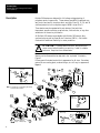
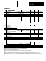
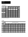
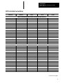
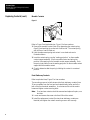
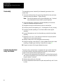
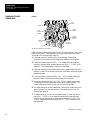
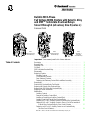
Bulletin 509 3-Phase
Full Voltage NEMA Starters with Eutectic Alloy
and SMPä Solid-state Overload Relays
Sizes 0 through 4 (all series), Size 5 (series L)
Renewal Parts
Size 1
with Eutectic Alloy
Overload Relay
Size 3
with Eutectic Alloy
Overload Relay
Size 5
with SMP-- 1
Solid-state
Overload Relay
Important: Save renewal parts list for future reference.
Table of Contents
Description . . . . . . . . . . . . . . . . . . . . . . . . . . . . . . . . . . . . . . . . . . . . . . . .
Renewal Parts . . . . . . . . . . . . . . . . . . . . . . . . . . . . . . . . . . . . . . . . . . . . . .
Operating Coils . . . . . . . . . . . . . . . . . . . . . . . . . . . . . . . . . . . . . . . . . . . . .
Coil Data . . . . . . . . . . . . . . . . . . . . . . . . . . . . . . . . . . . . . . . . . . . . . . . . . .
SMP Solid-state Overload Relay . . . . . . . . . . . . . . . . . . . . . . . . . . . . . . . . .
Disassembly . . . . . . . . . . . . . . . . . . . . . . . . . . . . . . . . . . . . . . . . . . . . . . .
Replacing Contacts . . . . . . . . . . . . . . . . . . . . . . . . . . . . . . . . . . . . . . . . . .
Movable Contacts . . . . . . . . . . . . . . . . . . . . . . . . . . . . . . . . . . . . . . . . .
Front Stationary Contacts . . . . . . . . . . . . . . . . . . . . . . . . . . . . . . . . . . .
Rear Stationary Contacts . . . . . . . . . . . . . . . . . . . . . . . . . . . . . . . . . . . .
Replacing the Stationary Contact Block and Base Assembly . . . . . . . . . . .
Reassembly . . . . . . . . . . . . . . . . . . . . . . . . . . . . . . . . . . . . . . . . . . . . . . .
Eutectic Alloy Overload Relay Test Module . . . . . . . . . . . . . . . . . . . . . . . . . .
Replacing the Eutectic Alloy Overload Relay . . . . . . . . . . . . . . . . . . . . . . . . .
Replacing the SMP Solid-state Overload Relay . . . . . . . . . . . . . . . . . . . . . . .
Replacing Current Transformer . . . . . . . . . . . . . . . . . . . . . . . . . . . . . . . . . .
Modifications . . . . . . . . . . . . . . . . . . . . . . . . . . . . . . . . . . . . . . . . . . . . . . .
Auxiliary Contacts . . . . . . . . . . . . . . . . . . . . . . . . . . . . . . . . . . . . . . . . .
Removal of Auxiliary Contact Block . . . . . . . . . . . . . . . . . . . . . . . . . . . .
Installing or Replacing an Auxiliary Contact Block . . . . . . . . . . . . . . . . . .
Auxiliary Contact for Eutectic Alloy Overload Relay . . . . . . . . . . . . . . . . .
Installing (N.O. or N.C) Auxiliary Contact for Eutectic Alloy Overload Relay .
Adding an N.O. or N.C. Auxiliary Contact in Place of Circuit Test module on
Eutectic Alloy Overload Relay for Sizes 3 and 4 Starters . . . . . . . . . . .
Replacing an N.O or N.C. Auxiliary Contact on an Overload Relay
(for sizes 3 and 4 Starters) . . . . . . . . . . . . . . . . . . . . . . . . . . . . . . . .
SMP, SMP-1, SMP-2, and SMP-3 are trademarks of Allen-Bradley Company, Inc.
2
3
4
4
5
7
7
8
8
9
9
10
10
11
11
12
14
14
14
15
16
16
17
19
Renewal Parts
Bulletin 509, Sizes 0 through 4 (all series)
Size 5 (series L)
Description
Bulletin 509 starters are designed for full voltage voltage starting of
polyphase squirrel cage motors. These starters meet NEMA standards, are
easy to wire and service, simple to select, and offer Class 10, 15, 20, and 30
overload protection in the complete range of NEMA sizes 00 to 9.
These starters may be operated with push buttons, float switches,
thermostats, pressure switches, snap switches, limit switches, or any other
suitable two or three wire pilot device.
All Bulletin 509 starters are available with Bulletin 592 eutectic alloy
overload relays as well as Smart Motor Protectors (SMPs) -- Solid-state
Overloads for additional flexibility in motor protection.
!
ATTENTION: To prevent electrical shock, disconnect from
power source before installing or servicing. Install in suitable
enclosure. Keep free from contaminants.
Starters can be disassembled as depicted in the “exploded” illustration,
Figure 1.
Primary parts illustrated are similar in appearance for all sizes. Secondary
parts such as mounting plate, overload relays, etc. will vary in appearance.
Figure 1
12
Contacts
3B
9
3C
16
6
11
3E
3D
1
10
3A
8
Note: See page 3 for corresponding description
of part and part numbers.
13C
15
7
4
3F
3
Sizes 3
and 4 only.
2
14
13
13D
14A
5
Size 5 only.
17
J Heater Element
Type J or W (Specify)
2
13B
13A
13E
17A
Renewal Parts
Bulletin 509, Sizes 0 through 4 (all series)
Size 5 (series L)
Renewal Parts
Item
1
Description of Renewal Parts
Contact Block Cover
Size 0
Size 1
Size 2
Size 3
Size 4
Part No.
Part No.
Part No.
Part No.
Part No.
Part No.
40410-499-01
40410-499-02
40420-499-01
40430-457-51
40440-456-51
42450-800-01
40420-498-01
40430-452-51
40440-453-51
42450-801-01
40420-495-02
40430-462-52
40440-462-52
42450-307-62
2Ë
Movable Contact Support and Armature
Assembly
3Ë
Stationary Contact Block and Base Assembly
3A
Saddle Clamp Assembly (for size 0 and 1)
—
—
—
—
3B
Lug
—
—
X-316012
40430-461-51
40440-461-51
42450-804-01
3C
Bolt
—
—
M-6289
3D
Front Terminal without Contact
3E
Rear Terminal without Contact
3F
Front/Rear Terminal Screw
4
Coil Cover
5
Tie Point Terminal
6
Auxiliary Contact Block (refer to page 14)
7
Operating Coil
8
Yoke (50-- 60 Hz)
9
Movable Contact
10
Contact Spring
11
Front Stationary Contact
12
Rear Stationary Contact
9-- 12
Single Pole Contact Set (includes (1) each
item 9-- 12)
40410-498-01 Series A
40410-498-03 Series B
Size 5 (Series L)Ê
40410-494-03
40410-494-04
X-225492
Ì
Ì
40410-496-01
Ì
40420-497-01
M-6532
M-6834
—
40430-022-02
40440-030-02
42450-302-52
40430-024-02
40440-314-51
40440-314-51
28168-107-26
28168-502-26
Í
40430-454-51
40440-454-51
42450-803-01
599-TP02
599-TP34
J 595-A (used as hold-in contact)
See Table on page 4
J 40410-497-01
J 40410-497-02
J 40430-455-51
J 40440-458-51
Order Single Pole Contact Set
J 40410-331-51
J 40410-331-52
J 40420-322-51
J 40430-300-51
J 40440-300-51
J 42450-805-01
40185-800-01
40185-801-01
40185-802-01
J 592-B0V16Î
13
Eutectic Alloy Overload Relay (includes item
13B test module)
13A
Eutectic Alloy Heater Element Screw
13B
Test Module (included with item 13 overload
relay)
13C
Overload Relay Auxiliary Contact
(included with item 13)
13D
Overload Mounting Plate
—
—
—
40430-045-02
40440-028-02
42450-028-02
13E
Jumper
—
—
—
—
—
42195-800-01
14
Smart Motor Protection (SMP) Solid-state
Overload Relay
14A
SMP Reset Bar Only (SMP-1, SMP-2)
15
Mtg. Screw w/Washer (3 req’d)
28169-100-26
28169-101-26
16
Mounting Plate for Eutectic Alloy, SMP-1ä,
SMP-2ä Ð
40410-124-02
40420-083-02
Mounting Plate for SMP-3ä Ð
40794-031-02
40794-032-02
17
Current Transformer
—
—
—
—
—
X-241563Î
17A
Transformer Spring
—
—
—
—
—
42450-806-01Î
42185-800-01
M-1552
—
40185-499-01
40430-459-51
42450-807-01
—
J 595-A34 Ï
—
See Table on page 5
40794-011-01
40430-460-51
40440-459-51Î
40430-044-02
40440-027-02
Parts indicated with J are recommended spare parts.
Ê This renewal parts list does not apply to Size 5 Series A construction. Refer to Publication 509-- 6.4.
Ë Less contacts, order Single Pole Contact Sets as required.
Ì Front and rear terminal assembly not available as a renewal part. Replace stationary contact block and base assembly
Í Front Terminal Screw Part No. 28168-503-26 and Rear Terminal Screw Part No. 28168-502-26.
Î For size 5 starter a current transformer assembly (which includes items 13, 15, 17, and 17A) can be ordered. Order Part No. 42452-800-01.
Ï Auxiliary mounted on right-hand side of overload relay provides N.O. contact function. Auxiliary mounted on left-hand side provides N.C. contact function.
Ð Size 0,1, and 2 Eutectic alloy, SMP-1, and SMP-2 overload relays are attached directly to the mounting plate. Sizes 3, 4, and 5 eutectic alloy, SMP-1, and SMP-2 overload
relays require a separate mounting plate. See Item 13D for sizes 3 and 4. Size 5 overload relay mounting plate is similar.
3
Renewal Parts
Bulletin 509, Sizes 0 through 4 (all series)
Size 5 (series L)
J
Operating Coils
Coil No.
AC Volts
Hz
24
60
115-- 120
60
110
50
Size 0- 1
Size 2
Size 3
Size 4
CB013
CC013
CD013
—
CB236
CC236
CD236
CE236
Size 5
Series LÊ
—
AF236
AF236
110-- 115
50
CB322
CC322
CD322
CE322
AF322
200-- 208
60
CB249
CC249
CD249
CE249
AF249
220-- 230
50
CB339
CC339
CD339
CE339
AF339
60
CB254
CC254
CD254
CE254
AF254
50
CB342
CC342
CD342
CE342
AF342
277
60
CB260
CC260
CD260
CE260
AF260
380
50
CB354
CC354
CD354
CE354
AF354
230-- 240
415
50
CB357
CC357
CD357
CE357
AF357
440-- 460
50
CB360
CC360
CD360
CE360
AF360
460-- 480
60
CB273
CC273
CD273
CE273
AF273
500
50
CB364
CC364
CD364
CE364
AF364
575-- 600
60
CB278
CC278
CD278
CE278
AF278
Parts indicated with J are recommended spare parts.
Ê For Size 5 Series A coils, refer to Publication 509-- 6.4.
Coil Data
Contactor
or
Starter
Size
Motor
Load
Voltamperes Burden for 60 Hz CoilsË
24 Volts
115- 120 Volts
200- 208 Volts
230- 240 Volts
460- 480 Volts
575- 600 Volts
Inrush
Sealed
Inrush
Sealed
Inrush
Sealed
Inrush
Sealed
Inrush
Sealed
Inrush
Sealed
0
2-- 5
192
29
192
29
192
29
192
29
192
29
192
29
1
2-- 5
192
29
192
29
192
29
192
29
192
29
192
29
2
2-- 3
240
29
240
29
240
29
240
29
240
29
240
29
2
4-- 5
315
38
315
38
315
38
315
38
315
38
315
38
3
2-- 3
660
45
660
45
660
45
660
45
660
45
660
45
3
4-- 5
840
58
840
58
840
58
840
58
840
58
840
88
4
2-- 3
—
—
1225
69
1225
69
1225
69
1225
69
1225
69
4
4-- 5
—
—
1490
96
1490
96
1490
96
1490
96
1490
96
5
(Series L)
2-- 3
—
—
1490
96
1490
96
1490
96
1490
96
1490
96
Ë
4
No.
of
Poles
For 50 Hz coils, consult your nearest Allen-Bradley Sales Office.
Renewal Parts
Bulletin 509, Sizes 0 through 4 (all series)
Size 5 (series L)
SMP Solid-state Overload Relay
Starter Size
Adjustment
Range (A)
Class 10
Cat. No.
Class 20
Cat. No.
Class 30
Cat. No.
SMP-1 Overload Relay Manual Reset, Phase Loss Protection, Class 10, 20, or 30
0, 1
0.19 to 0.6
592-A1BA
592-A2BA
592-A3BA
0, 1
0.32 to 1.0
592-A1CA
592-A2CA
592-A3CA
0, 1
1.0 to 2.9
592-A1DA
592-A2DA
592-A3DA
0, 1
1.6 to 5.0
592-A1EA
592-A2EA
592-A3EA
0, 1
3.7 to 12
592-A1FA
592-A2FA
592-A3FA
0, 1
5.7 to 18
592-A1GA
592-A2GA
592-A3GA
1
12 to 38
592-A1HA
592-A2HA
592-A3HA
2
5.7 to 18
592-A1GC
592-A2GC
592-A3GC
2
12 to 38
592-A1HC
592-A2HC
592-A3HC
2
14 to 45
592-A1JC
592-A2JC
592-A3JC
3
14 to 45
592-A1JD
592-A2JD
592-A3JD
3
23 to 75
592-A1KD
592-A2KD
592-A3KD
3
66 to 110
592-A1LD
592-A2LD
592-A3LD
4
23 to 75
592-A1KE
592-A2KE
592-A3KE
4
66 to 110
592-A1LE
592-A2LE
592-A3LE
4
57 to 180
592-A1ME
592-A2ME
592-A3ME
5
96 to 300
592-A1NF
592-A2NF
592-A3NF
SMP-1 Overload Relay Automatic/Manual Reset, Phase Loss Protection, Class 10, 20, or 30
0, 1
0.19 to 0.6
592-A4BA
592-A5BA
592-A6BA
0, 1
0.32 to 1.0
592-A4CA
592-A5CA
592-A6CA
0, 1
1.0 to 2.9
592-A4DA
592-A5DA
592-A6DA
0, 1
1.6 to 5.0
592-A4EA
592-A5EA
592-A6EA
0, 1
3.7 to 12
592-A4FA
592-A5FA
592-A6FA
0, 1
5.7 to 18
592-A4GA
592-A5GA
592-A6GA
1
12 to 38
592-A4HA
592-A5HA
592-A6HA
2
5.7 to 18
592-A4GC
592-A5GC
592-A6GC
2
12 to 38
592-A4HC
592-A5HC
592-A6HC
2
14 to 45
592-A4JC
592-A5JC
592-A6JC
3
14 to 45
592-A4JD
592-A5JD
592-A6JD
3
23 to 75
592-A4KD
592-A5KD
592-A6KD
3
66 to 110
592-A4LD
592-A5LD
592-A6LD
4
23 to 75
592-A4KE
592-A5KE
592-A6KE
4
66 to 110
592-A4LE
592-A5LE
592-A6LE
4
57 to 180
592-A4ME
592-A5ME
592-A6ME
5
96 to 300
592-A4NF
592-A5NF
592-A6NF
Continued on next page.
5
Renewal Parts
Bulletin 509, Sizes 0 through 4 (all series)
Size 5 (series L)
SMP Solid-state Overload Relay (cont.)
Starter Size
Adjustment
Range (A)
Class 10, 15, 20, or 30
Cat. Nos.
SMP-2 Overload Relay Automatic/Manual Reset, Field Selectable Trip Class 10, 15, 20, or 30,
Phase Loss, Jam, and Ground Fault Protection
0, 1
0.19 to 0.6
592-B1BA
0, 1
0.32 to 1.0
592-B1CA
0, 1
1.0 to 2.9
592-B1DA
0, 1
1.6 to 5.0
592-B1EA
0, 1
3.7 to 12
592-B1FA
0, 1
5.7 to 18
592-B1GA
1
12 to 38
592-B1HA
2
5.7 to 18
592-B1GC
2
12 to 38
592-B1HC
2
14 to 45
592-B1JC
3
14 to 45
592-B1JD
3
23 to 75
592-B1KD
3
66 to 110
592-B1LD
4
23 to 75
592-B1KE
4
66 to 110
592-B1LE
4
57 to 180
592-B1ME
5
96 to 300
592-B1NF
SMP-3 Overload Relay Automatic/Manual Reset, Field Selectable Trip Class 10, 15, 20, or 30,
Phase Loss, Jam Protection, Ground Fault Protection and Communication Capability ÊËÌ
Ê
Ë
Ì
Í
6
0, 1
0.7 to 2.5
592-C1DA
0, 1
2 to 10
592-C1FA
0, 1
7 to 37
592-C1HA
2
7 to 37
592-C1HC
2
20 to 75
592-C1KC
3
20 to 90
592-C1LD
4
40 to 180
592-C1ME
5Í
70 to 300
592-C1NFD
For NEMA starters sizes 0-- 2, a new mounting plate is required for retrofit to existing Bulletin 509 starters. For sizes 0-- 1 starters, order Part No. 40410-124-02 and for size 2
starters, order Part No. 40420-083-02.
Allen-Bradley recommends using 120 or 240 V AC coils on all SMP-3 NEMA starters. When using coil voltages other than 120 or 240 V AC, consult your nearest Allen-Bradley
Sales Office.
The ratings of the triacs and the hard output contact (relay) internal to the SMP-3 must not be exceeded. See the SMP-3 User’s Manual for actual ratings.
This SMP-3 overload relay has an interposing relay with a 120 V AC coil.
Renewal Parts
Bulletin 509, Sizes 0 through 4 (all series)
Size 5 (series L)
Disassembly
!
ATTENTION: To prevent electrical shock, disconnect from
power source before installing or servicing. Install in suitable
enclosure. Keep free from contaminants.
The following procedures and techniques are suggested to aid in the
disassembly and reassembly of a typical motor starter. It is not necessary to
remove the starter from its enclosure or to remove the line wiring. Refer to
exploded view, Figure 1 for item numbers.
1. Remove all control wires from the operating coil (item 7) and tie point
terminal (item 5).
2. Loosen two captive screws and lift off the contact block cover (item 1).
3. Loosen four captive screws from the coil cover (item 4). The tie point
terminal is now free to be removed, if it is to be replaced.
4. With the coil cover screws loosened, the auxiliary contact block(s)
(item 6) can be removed and the coil cover lifted off.
5. Lift out the movable contact support and armature assembly (item 2), the
yoke (item 8) and the operating coil (item 7) as a unit. The yoke and the
operating coil can now be lifted up and out of the movable contact
support assembly.
Replacing Contacts
When severe contact wear is evidenced, it is recommended that all contacts
be replaced, which will guard against uneven contact closings. Be sure to
check contact spring flexibility and replace if necessary. Order the required
number of single pole contact sets from the part listings on Page 3. Follow
steps 1--5 under Disassembly.
Torque for Stationary Contact Replacement
Size
Front and Rear Torque
(approximately)
0
8-- 10 lbs.-in.
1
14-- 17 lbs.-in.
2
50 lbs.-in.
3
90 lbs.-in.
4
180 lbs.-in.
5
180 lbs.-in.
Note: Torque for coil cover sizes 0 to 2 are approximately 14--17 lbs.-in.
Sizes 3 to 5 are approximately 25--30 lbs.-in.
Continued on next page.
7
Renewal Parts
Bulletin 509, Sizes 0 through 4 (all series)
Size 5 (series L)
Replacing Contacts (cont.)
Movable Contacts
Figure 2
“Seating
Projection”
Refer to Figure 2 and exploded view, Figure 1 for item numbers.
1. Remove the movable contact (item 9) by depressing the contact spring
(item 10) and pushing the contact out to either side. The contact spring
will fall free or can be lifted out.
2. Hold the replacement spring and contact in one hand as shown in
illustration above.
3. Insert the contact spring over the “seating projection” on the movable
contact support assembly. Slip the movable contact and spring into
position in the opening on the movable contact support assembly. Rock
the spring into position over the seating projection on the movable contact
support and the movable contact.
4. Check to determine that the spring is holding the contact in a centered
position.
Front Stationary Contacts
Refer to exploded view, Figure 1 for item numbers.
The mounting screws or bolts that secure the front stationary contacts (item
11) are accessible from the front and are located directly below and to the
back of the front terminal assemblies. A socket wrench should be used to
loosen and tighten contact securing bolts.
Note: Front and rear contacts should be removed and replaced in pairs, one
at a time.
1. Loosen and remove the screw or bolt and lift out the contact.
2. Install the replacement contact (front and rear stationary contacts are
identical) and tighten the contact mounting screw or bolt securely.
8
Renewal Parts
Bulletin 509, Sizes 0 through 4 (all series)
Size 5 (series L)
Rear Stationary Contacts
Refer to exploded view, Figure 1 for item numbers.
The mounting screws or bolts that secure the rear stationary contacts (item
12) are accessible from the top and are located at an angle in the cavities
directly behind the front terminal assemblies.
1. Loosen and remove the mounting screw or bolt while holding the contact
within the contact block assembly.
2. Push the loose contact up and out or allow it to drop down.
3. Install the replacement contact from the top catching it from within the
contact block assembly.
4. Insert the mounting screw or bolt and tighten securely.
Replacing the Stationary Contact Block and Base Assembly
Refer to exploded view, Figure 1 for item numbers.
The block and base assembly (item 3) can be removed from a partially
disassembled starter, if necessary. First follow steps 1--5 under Disassembly.
The block and base assembly is connected to the incoming lines and the
overload relay (item 13).
1. Remove the line wiring and label or mark all wires.
2. The block and base assembly is connected by bus to the overload relay.
Loosen, but do not remove the three terminal screws that connect the
block and base assembly to the overload relay for sizes 0, 1, 2, and 5
starters.
For sizes 3 and 4 starters, remove the three bolts that connect the block
base assembly to the overload relay. Then turn the starter over so that the
back of the mounting plate faces up. Remove the two screws with
washers. The overload relay with the mounting plate can be removed to
expose the mounting screw with washer (item 15).
3. The block and base assembly is secured to the mounting plate (item 16)
by three mounting screws with washers (item 15). Remove these screws
and the stationary contact block and base assembly (item 3) can be lifted
up and out.
4. If new contacts are not being installed, remove stationary contacts one at
a time from the old block and base assembly and install them in the same
positions in the new assembly. See instructions under Replacing
Contacts on page 7. Follow those instructions also if installing new
contact sets.
5. Install the replacement block and base assembly and secure with the three
screws with washers and tighten securely.
6. Retighten terminal screws to overload relay bus securely.
7. Reconnect line wiring.
9
Renewal Parts
Bulletin 509, Sizes 0 through 4 (all series)
Size 5 (series L)
Reassembly
The reassembly process is basically the disassembly procedures in the
reverse order.
1. Secure the overload relay to the mounting plate with the two previously
removed screws with washers. Tighten securely.
Note: Place the flat washers next to the molded plastic part. Overload
relay embossments are provided for proper alignment.
2. Secure the stationary contact block and base assembly with the three
screws with washers and tighten securely.
3. Retighten securely the three terminal screws to overload bus.
4. Insert the yoke into the operating coil. It is designed to fit only one way.
5. Insert the yoke and operating coil into the movable contact support
assembly.
6. Insert all three parts as a unit into the stationary contact block and base
assembly.
7. Replace the coil cover. Check the tie point terminal for proper position.
Tighten the coil cover screws securely.
8. Replace contact block cover and tighten screws securely.
9. Install the auxiliary contact block(s). Refer to detailed instructions under
Installing or Replacing an Auxiliary Contact Block on page 15.
10. Properly reconnect all wiring and tighten the screws.
Eutectic Alloy Overload
Relay Test Module
The eutectic alloy overload relay is equipped with a test module (item 13b)
on the right hand side, that allows opening the normally closed overload
contact for test purposes,without tripping the relay.
1. To remove, use an appropriate size screwdriver. Hold the blade vertically
and insert the screwdriver tip into the slot provided on the test module, to
the point where it “bottoms”.
2. Slide the test module out to the right.
3. Slide the replacement test module into place and press firmly until it locks
in place.
10
Renewal Parts
Bulletin 509, Sizes 0 through 4 (all series)
Size 5 (series L)
Replacing the Eutectic Alloy
Overload Relay
Refer to exploded view, Figure 1 for item number.
The overload relay (item 13) is connected to the block and base assembly
(item 3), mounting plate, and load lines.
1. Remove the control wire(s) from the overload relay and label wires if
necessary.
2. Remove the load wiring from the overload relay terminals. Label all the
wires to prevent installing the wires incorrectly.
3. Loosen but do not remove the three terminal screws that connect the
overload relay bus to the block and base assembly, approximately three
turns.
Note: Terminal screws on sizes 3, 4, and 5 must be removed.
4. The overload relay is secured to its mounting plate by two mounting
screws with washers. Remove these screws, lift the overload relay away
from the mounting plate, then slide it down and out.
Note: Size 5 has an additional mounting plate as part of the overload
relay assembly.
5. The replacement overload relay for size 5 will be furnished secured to a
mounting plate. Remove and discard the mounting plate. Install the
replacement overload relay being sure the bus connects properly to the
terminals on the stationary contact block and base assembly. Secure the
overload relay to the mounting plate with the two previously removed
screws with washers.
Note: Place the flat washers next to the molded plastic part and tighten
securely.
6. Retighten securely the three terminal screws to overload relay bus.
7. Reconnect control and load wiring. Tighten the wires into the wire
clamps or lugs to the values specified on the equipment.
Replacing the SMP
Solid-state Overload Relay
Figure 3
Illustration shows size 1 starter.
11
Renewal Parts
Bulletin 509, Sizes 0 through 4 (all series)
Size 5 (series L)
Replacing Current
Transformer
Figure 4
Load
Terminal
Starter
Nylon
Standoff
Nylon
Spacer
Insulator
Overload
Relay
Current
Transformer
Module
Current
Transformer
Lug
Illustration shows part of a size 5 starter.
Refer to Figure 4 and exploded view, Figure 1 for item numbers. The current
transformers (Item 17) are attached to the current transformer module and
connected to the overload relay (Item 13).
1. Label and remove all wires from the overload relay. Remove the
grounding screw from the current transformer module mounting plate.
2. Loosen and remove the two 10-32 ¢ 1 in. screws and washers which
secure the overload relay mounting plate to the 3/4 in. ¢ 1-9/16² nylon
standoffs. The overload relay is now free of the starter.
3. Label and remove the terminal wiring from the current transformer to be
replaced. Label to indicate which wire was connected to the terminal near
the polarity mark.
4. Loosen and remove the three 5/16 in.-24 ¢ 3/4 in. hexagon head load
terminal screws connecting the load terminals to the contactor.
5. Loosen and remove the four 1/4 in.-28 ¢ 3/4 in. hexagon head screws
connecting the current transformer module to the mounting plate. The
current transformer module is now free of the mounting plate.
6. To replace the center current transformer: Remove the rectangular nylon
spacer insulator from the load terminal. The transformer can now be
removed and replaced.
7. To replace either of the outer current transformers: Loosen and remove
the 3/4 in. ¢ 1-9/16 in. nylon standoff attached to the load terminals.
Turn the current transformer module over and remove the 5/16 in.-24 ¢
1-1/4 in. hexagonal head screw and the 10-32 ¢ 3/4 in. screw from the
load terminals.
Continued on next page.
12
Renewal Parts
Bulletin 509, Sizes 0 through 4 (all series)
Size 5 (series L)
Turn the module back over and slide the load terminals out of the
transformer. The current transformer spring (Item 17A) and current
transformer can now be removed from the module. Note the position of
the spring before removing.
The replacement current transformer and spring are placed into the
module so that the rectangular holes in the center of the spring and
transformer are aligned and the spring is below the transformer, concave
side facing up. Slide the load terminal through the transformer so that the
load terminal lug is on the same side and in the same direction as the
other load terminal lugs.
Turn the module over and refasten the 5/16 in.-24 ¢ 1-1/4 in. screw
(torque to 50 lbs.-in) and the 10-32 ¢ 3/4 in. screw (torque to 30 lbs.-in.)
to the load terminal. Turn the module over (right side up) and refasten the
3/4 in. ¢ 1-9/6 in. nylon standoff to the load terminal torque to
16 lbs.-in.)
8. Refasten the wiring onto the current transformer terminals, observing
polarity mark on transformers and labels on wires from step 3. Tighten
terminal screws securely.
9. Place the center transformer’s nylon spacer insulator over the center load
terminal so that the side with the angled indent faces away from the
current transformer and the circular indent faces toward the backplate.
The current transformer module assembly is now ready to be secured to
the contactor and mounting plate.
10. Place the transformer module’s line terminals over the contactor load
terminals, aligning the center transformer’s nylon spacer insulation so that
its circular indent fits over the hexagon head of the contactor’s lower
mounting screw, and the side of the spacer with the angled indent fits
flush against the Stationary Contact Block and Base Assembly (Item 3).
Align the mounting holes and refasten using the three 3/16 in.-24 ¢
3/4 in. hexagon head screws tightened to 80 lbs.-in. torque.
11. Refasten the current transformer module to the mounting plate using the
four 1/4 in.-28 ¢ 3/4 in. hexagon head screws tightened to 50 lbs.-in.
12. Refasten the green grounding wire and screw securely to the mounting
plate.
13. Refasten the overload relay assembly to the standoffs using the two
10-32 ¢ 1 in. screws and washers (torque to 5 lbs.-in.).
14. Securely reconnect labeled control wires according to labels attached to
wires in step 1.
13
Renewal Parts
Bulletin 509, Sizes 0 through 4 (all series)
Size 5 (series L)
Modifications
The modifications following are common. For information on any
modification or accessory not listed, refer to any Allen-Bradley sales office.
Auxiliary Contacts
Figure 5
Cat. No. 595-A
(1 N.O.)
Cat. No. 595-AB
(1 N.O.- 1 N.C.)
Bulletin 509 Starters are designed to accept one to four Bulletin 595
Auxiliary Contact Blocks which can provide up to six auxiliary contacts of
the user’s choice. Auxiliary contact blocks mount beneath the coil cover at
positions marked P1, P2, P3, or P4 on the coil cover. They can be mounted
without the use of tools or additional hardware.
Auxiliary Contact Description
One Normally Open (1 N.O.)
Cat. No. J
595-A
One Normally Closed (1 N.C.)
595-B
One Normally Closed (1 N.C. Late Break)
595-BL
One Normally Open - One Normally Closed
(1 N.O. - 1 N.C.)
595-AB
Two Normally Open (2 N.O.)
595-AA
Two Normally Closed (2 N.C.)
595-BB
Parts indicated with J are recommended spare parts.
Removal of Auxiliary Contact Block
Loosen coil cover screws and lift out the auxiliary contact block by pivoting
its back end away from starter.
Continued on next page.
14
Renewal Parts
Bulletin 509, Sizes 0 through 4 (all series)
Size 5 (series L)
Installing or Replacing an Auxiliary Contact Block
The movable contact support and armature assembly must be completely
open (the word “OFF” totally visible). The coil cover must be in place and
properly secured.
Figure 6
Align Arrows
Molded Tabs
1. Align arrows molded on auxiliary contact block. See Figure 6.
2. Locate molded tabs on side with arrows. See Figure 6.
3. Hook tabs under coil cover at any pocket location marked P1, P2, P3,
or P4.
Figure 7
Exert
Pivotal
Force
4. Exert a pivotal force at the lower end of the block until it snaps into place.
Refer to Figure 7.
15
Renewal Parts
Bulletin 509, Sizes 0 through 4 (all series)
Size 5 (series L)
Modifications (cont.)
Auxiliary Contact for Eutectic Alloy Overload Relay
for Sizes 0, 1, 2, and 5 Starters
Figure 8
Cat. No. 595-A02 (N.O.)
Cat. No. 595-B02 (N.C.)
This contact can easily be added to the block type eutectic alloy overload
relay used on Bulletin 509 sizes 0, 1, 2, and 5 starters. It mounts in place of
the standard eutectic alloy overload relay test module. A typical application
would be for an alarm circuit indicating when the overload relay has tripped.
Installing (N.O. or N.C) Auxiliary Contact for Eutectic Alloy Overload
Relay for Sizes 0, 1, 2, and 5 Starters
This contact can be installed on Bulletin 509 sizes 0, 1, 2, and 5 starters.
First remove the test module as indicated below.
Figure 9
Test
Module
Mounting
Screw
Auxiliary
Contact
Block
1. Use an appropriate size screwdriver.
2. Hold the blade vertically and insert the screwdriver tip into the slot
provided on the test module to the point where it “bottoms.” See
Figure 9.
3. Slide the test module out to the right.
Continued on next page.
16
Renewal Parts
Bulletin 509, Sizes 0 through 4 (all series)
Size 5 (series L)
4. Slide the N.O. or N.C. auxiliary contact block into the overload relay in
place of the test module.
5. Secure the block, using the mounting screw provided, through the hole in
the overload relay housing. See Figure 9.
Adding an N.O. or N.C. Auxiliary Contact in Place of Circuit Test Module
on Eutectic Alloy Overload Relay for Sizes 3 and 4 Starters
1. Insert proper size screwdriver in slot at the top of Circuit Test Module;
press towards mounting plate and pull module from relay. Refer to
Figure 10.
Figure 10
Overload
Relay
Housing
Circuit
Test
Module
Screwdriver
2. Loosen two screws holding sections of auxiliary contact together. Refer
to Figure 11.
Figure 11
Loosen
These
Screws
Stationary
Contacts
Movable
Contacts
Continued on next page.
17
Renewal Parts
Bulletin 509, Sizes 0 through 4 (all series)
Size 5 (series L)
Modifications (cont.)
3. Place the section containing the stationary contacts above the retaining
ribs on the overload relay and the section containing the movable contacts
below the same retaining ribs. Refer to Figure 12.
Figure 12
Retaining Ribs
4. Securely tighten two screws to fasten the two sections of the auxiliary
contact together and to the overload relay housing retaining ribs. Refer to
Figure 13.
Figure 13
Tighten
Screws
Securely
Retaining
Rib
5. Wire N.O. auxiliary contact as required.
18
Renewal Parts
Bulletin 509, Sizes 0 through 4 (all series)
Size 5 (series L)
Replacing an N.O. or N.C.
Auxiliary Contact on an
Overload Relay (for Sizes 3
and 4 Starters)
The function of the auxiliary is N.O. when mounted on the end of the relay
furthest from the reset button and N.C. when mounted on the end nearest the
reset button.
Note: N.O. and N.C. are stamped on the relay housing to indicate function.
1. Remove control wiring from terminals of auxiliary contact being
replaced.
2. Remove the auxiliary contact by loosening the two screws that clamp it to
the overload relay, sliding the two sections of the contact apart
(approximately 1/8 in.) and removing them from the relay. See Figure 14.
Figure 14
Loosen
Two
Screws
Slide Apart
and Remove
3. Install new contact following instructions given above for adding
auxiliary contact.
4. Replace control wires removed in step 1 to terminals of new auxiliary
contact.
19
Renewal Parts
Bulletin 509, Sizes 0 through 4 (all series)
Size 5 (series L)
20 Publication 509-6.0 May 1996
Copyright 1996 Allen-Bradley Company, Inc., a Rockwell International company Printed in USA
Supersedes Publications 509-6.0 November 1976, 509-6.1 January 1977, 509-6.2 February 1981, 509-6.3 February 1981, 509-6.4.1 November 1982