1
Connections & Setup
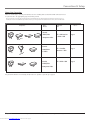
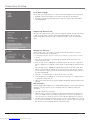
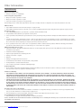
Explanation of Jacks
This section describes the jacks you can use to make connections. There are several ways to connect components
to your TV.
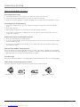
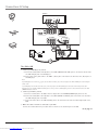
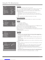
DVI-HDTV Input
Lets you connect an HD receiver with a DVI output.
•
DVI (Digital Visual Interface) Provides an uncompressed, digital video interface developed
for high-bandwidth digital connection. It supports the overlay of high-resolution graphics
needed by some electronic program guide navigation and other interactive services. DVI,
when combined with HDCP (High bandwidth Digital Content Protection) technology, creates
a protected digital connection. The signal speed of the DVI connection is 1080i for HDTV at a
rate of 1.78 Gigabits per second.
•
L/MONO (Audio) Provides left audio connection when using the DVI jack. The left audio
connector is usually white.
•
R (Audio) Provides right audio connection when using the DVI jack. The right audio
connector is usually red.
L/MONO
DVI-HDTV
R
Note: Remember to connect the left and right audio cables because the DVI cable carries only the picture signal,
not the sound.
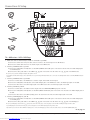
COMPONENT INPUTS
PR
L/MONO R
Y
PB
PR
L/MONO R
CMP2
PB
CMP1
Y
COMPONENT INPUTS
S-VIDEO
S-VIDEO
V
L/MONO
R
VID2
R
VID1
L/MONO
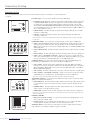
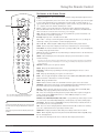
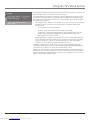
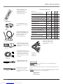
CMP1 Y, PB, PR (Component Video) Provides optimum picture quality because the video is
separated into three signals. Use three video-grade cables for the connection. When using
CMP1 Y, PB, PR, make sure to connect left and right audio cables to the CMP1 L/MONO and R
Audio Input jacks.
•
CMP1 L/MONO (Audio) Provides left audio connection. The left audio connector is usually
white.
•
CMP1 R (Audio)
•
CMP2 Y, PB, PR, and L/MONO and R Audio Allows you to connect a second component
video source. Their description is the same as CMP1 above. When using CMP2 Y, PB, PR, make
sure you connect the left and right audio cables to the CMP2 Audio jacks.
Provides right audio connection. The right audio connector is usually red.
COMPOSITE INPUTS Lets you connect another component such as a VCR, DVD player, or
laserdisc player. Its AUDIO jacks are the same as described for CMP1 above.
COMPOSITE INPUTS
V
Lets you connect a component video source, such as a DVD player.
•
•
VID1 S-VIDEO Provides better picture quality than the video jacks (VID1 and 2 Video)
because the color part of the signal is separated from the black and white part of the picture.
When using VID1 S-VIDEO, make sure to connect left and right audio cables to the VID1 L/
MONO and R Audio Input jacks.
•
VID1 V (Video) Provides composite video connection. The video connector is usually yellow.
•
VID2 S-VIDEO, V and L/MONO and R Audio Allows you to connect a component such as
a VCR, DVD player, or laserdisc player. Their description is the same as VID1 above.
Note: Do not connect an S-Video and Video cable at the same time in either VID1 or VID2 jacks.
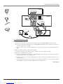
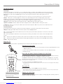
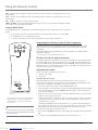
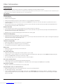
AUDIO/VIDEO OUTPUTS Lets you connect an amplifier or audio receiver for improved sound
quality or an external video monitor.
AUDIO/VIDEO OUTPUT
V
FIXED AUDIO
R
L
VARIABLE
AUDIO
SUBWOOFER
L
•
FIXED AUDIO L/R Provides fixed-level audio output from the TV. This audio output is ideal
for connecting to an A/V receiver when you want to control the volume through the A/V
receiver.
•
VARIABLE AUDIO Provides variable-level audio output. Volume levels are controlled by the
volume controls on the TV and remote control.
•
SUBWOOFER Provides lower bass audio frequencies out from the TV and to a subwoofer.
R
Note: If you’ve connected a subwoofer, make sure you set the External Subwoofer option in the Sound menu. Go to
page 22 for instructions.
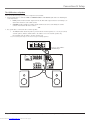
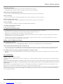
EXTERNAL SPEAKERS
EXT/INT
+
+
RIGHT
LEFT
•
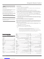
Right and Left Speaker Terminals
TV to receive left and right sound.
Let you connect external left and right speakers to the
•
EXT/INT (switch) Lets you turn the TV’s internal speakers on or off. EXT sends audio to
external speakers only. INT sends audio to the TV’s internal speakers only.
ANTENNA/CABLE Lets you connect a coaxial cable to receive the signal from the antenna,
cable, cable box, or if using the examples on pages 6-8, a VCR.
EXTERNAL SPEAKERS
10
Graphics contained within this publication are for representation only.
Downloaded from www.Manualslib.com manuals search engine
Chapter 1