1
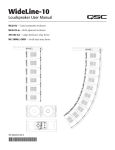
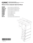
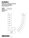
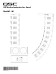
1675 MacArthur Blvd., Costa Mesa, CA, 92626 USA
Main Number (714) 754-6175 Sales & Marketing (714) 957-7100 or toll free (USA only) (800) 854-4079
Customer Service(714) 957-7150 or toll free (USA only) (800) 772-2834
WideLine Series Loudspeaker System User Manual
WL218-sw subwoofer line array loudspeaker
DB218-sw dolly board
AF218-sw subwoofer array frame
*TD-000232-00*
TD-000232-00 revB
IMPORTANT SAFETY PRECAUTIONS
Install in accordance with QSC Audio Product's instructions and under the supervision of a licensed Professional Engineer.
WARNING!
Before placing, installing, rigging, or suspending any speaker product, inspect all hardware, suspension, cabinets, transducers, brackets and
associated equipment for damage. Any missing, corroded, deformed, or non-load rated component could significantly reduce the strength of
the installation, placement or array. Any such condition severely reduces the safety of the installation and should be immediately corrected.
Use only hardware which is rated for the loading conditions of the installation and any possible short-term, unexpected overloading. Never
exceed the rating of the hardware or equipment.
Consult a licensed, Professional Engineer regarding physical equipment installation. Ensure that all local, state and national regulations
regarding the safety and operation of suspended equipment are understood and adhered to.
Warranty (USA only; other countries, see your dealer or distributor)
Disclaimer
QSC Audio Products, LLC is not liable for any damage to amplifiers or any other equipment that is caused by negligence or improper
installation and/or use of this loudspeaker product.
QSC Audio Products 3 Year Limited Warranty
QSC Audio Products, LLC (“QSC”) guarantees its products to be free from defective material and / or workmanship for a period of three (3)
years from date of sale, and will replace defective parts and repair malfunctioning products under this warranty when the defect occurs
under normal installation and use - provided the unit is returned to our factory or one of our authorized service stations via prepaid transportation with a copy of proof of purchase (i.e., sales receipt). This warranty provides that the examination of the return product must
indicate, in our judgment, a manufacturing defect. This warranty does not extend to any product which has been subjected to misuse,
neglect, accident, improper installation, or where the date code has been removed or defaced. QSC shall not be liable for incidental and/
or consequential damages. This warranty gives you specific legal rights. This limited warranty is freely transferable during the term of the
warranty period.
Customer may have additional rights, which vary from state to state.
In the event that this product was manufactured for export and sale outside of the United States or its territories, then this limited warranty shall not apply. Removal of the serial number on this product, or purchase of this product from an unauthorized dealer, will void this
limited warranty.
Periodically, this warranty is updated. To obtain the most recent version of QSC’s warranty statement, please visit www.qscaudio.com.
Contact us at 800-854-4079 or visit our website at www.qscaudio.com.
© Copyright 2006, QSC Audio Products, LLC
QSC® is a registered trademark of QSC Audio Products, LLC
Speakon® is a registered trademark of Neutrik® and the names of Neutrik® products referenced herein are either trademarks and/or service marks of Neutrik®.
All trademarks are the property of their respective owners.
“QSC” and the QSC logo are registered with the U.S. Patent and Trademark Office
2
Introduction
The WL218-sw is a dual 18-inch (457mm) subwoofer designed for suspended or ground stacked use in touring or installed concert applications. With an impressive combination of sonic impact, low-frequency extension, and accuracy, the WL218-sw is an ideal companion
for QSC's WideLine as well as other professional sound reinforcement systems.
Suspension of WL218-sw subwoofers is easy using the AF218-sw, a heavy-duty array frame constructed of welded 6061-T6 aluminum. In
ground-supported applications, the WL218-sw may be stacked using the interlocking feet and recess features machined into the enclosure's ends.
The woofers incorporate a double layer spider and triple roll surround for extended and controlled excursion at high power. The 4-inch
(102mm) voice coil is wound on a fibreglass former to prevent deformation at high operating temperatures and is extensively vented to
reduce power compression. An aluminum demodulating ring is employed for low distortion. Each woofer is housed in a separate chamber
to prevent failure of one driver from causing damage to the other. A 14-gauge (1.9mm) powder coated steel grill protects the drivers.
Enclosure construction features premium quality birch plywood finished in an environmentally friendly, water-borne, polymer finish that's
tough and field repairable. Extensive internal bracing and exclusive use of birch plywood minimizes acoustic loss due to panel resonance.
Ample port area allows air to move freely with minimal turbulence. The ports are arranged so as to eliminate asymmetrical loading of the
woofers, further protecting the drivers.
Transport and handling features are also provided in the WL218-sw's design. No matter how the box is deployed, one of the dozen handles will be where it needs to be. The included dolly has rugged, 3.5-inch ball bearing casters and an easy-to-use, snap-on mechanism for
attachment to the enclosure.
For users of QSC's digital audio transport and processing products, QSControl.net / Basis DSP files tuned for use with WL218-sw are
available for download. Visit us at http://www.qscaudio.com for the latest products, and news.
1
WL218-sw Loudspeaker
2
1- Handles
2- Stacking recesses
6
3
3- Stacking feet
4- Receiver tubes with ball lock pins & captive articulated joints
5
4
5- Dolly board latch plates
6- Grille
7- Skids
8- Serial number plate
9- Rear link and receiver block
10- Input connector plate
7
8
9
10
3
Introduction (continued)
1
DB115-sw Dolly Board
1- Pads
2- Casters
2
3
3- Stacking Recesses
4- Latches
5- Handling Cut-outs
4
6
6- Handles
5
2
1
AF218-sw Array Frame
1- Ground stacking bumpers
2- Center support bar
5
3- Shackle holes (accept 3/4” (20 mm) screw pin anchor shackle)
3
Use only shackle holes for suspension of array!
4- Rigging plate, retaining bolts, and link assembly with ball lock pin
5- Receiver blocks
4
2
3
AF218-sw Array Frame Feet (Optional)
1- Frame Feet, 4 each
2- Screw, Button Head, Torx drive, 1/4-20 x 3/4 Long, 8 each
3- Lock Nut with Nylon Insert, 1/4-20, 8 each
1
4
Rigging
Rigging the WideLine Array is simple and flexible. Enclosures are pinned together with quick-release ball-lock pins. The AF218-sw array frame
supports flown array applications and can be inverted for ground stack applications. The enclosures can also be ground stacked without a frame
using the stacking feet and recesses integral to the enclosure’s design.
Rules for Suspension
•Correct use of all suspension hardware and components is imperative in sound system rigging and deployment.
•Always calculate suspended loads before lifting to ensure suspension components and hardware are used within their respective load limits.
•Research local codes and regulations to fully understand the requirements for suspended loads in the venue in which the equipment is to be
suspended.
•Use only shackle holes for suspension of array.
•Be absolutely certain of the integrity of any structural member intended to support suspended loads. Hidden structural members can have
hidden structural weakness.
•Consult a Professional Mechanical or Structural Engineer licensed in the jurisdiction of the sound system installation to review, verify, and
approve all attachments to the building or structure.
•Never assume anything- Owner or third-party supplied suspension attachment points may not be adequate for the loads to be suspended.
•Employ the services of a Professional Rigger for hoisting, positioning, and attaching the equipment to the supporting structure.
•Always inspect all components (enclosures, suspension brackets, pins, frames, bolts, nuts, slings, shackles, etc.) for cracks, wear, deformation, corrosion, missing, loose, or damaged parts that could reduce the strength of the assembly before lifting. Discard any worn, defective, or
suspect parts and replace them with new appropriately load-rated parts.
Shock Loading
When a load is either moved or stopped, its static weight is magnified. Sudden movements can magnify the static weight several times. This
magnification of static weight is termed "shock loading". Shock loading poses a danger to equipment and workers. The effects of shock loading
can be instantaneous, or they may remain undetected unless the equipment is visually damaged. Avoiding shock loading requires careful planning and knowledge of equipment, rigging, and lifting practices.
Shock loading of equipment and structures is usually confined to lifting and installation, but natural forces (winds, earthquakes) can impose
shock loads several times the static load. This is why structures and suspension equipment must be capable of supporting several times the
weight of the equipment suspended.
WideLine Working Load Limits and Design Factors
Table 1 lists the WideLine suspension components and provides Working Load Limit data at various Design Factors. The tabulated Design Factors
are for static loads only. The choice of which Design Factor to use will depend upon the jurisdiction and venue of installation, as well as the conditions of suspension. Dynamic conditions are determined by unknown, installation-specific factors and should be referred to a Licensed Structural Engineer for clarification before proceeding with any suspension of the equipment. The data presented is based upon the listed component
weights:
Table 1: WideLine WL218-sw System Working Load Limits
Component
Weight
5:1 Design Factor
7:1 Design Factor
10:1 Design Factor
WL218-sw Loudspeaker
206 lb (93.4 kg)
3400 lb(1540 kg)
2400 lb (1090 kg)
1700 lb (771 kg)
AF218-sw Array Frame
80 lb (36.3 kg)
3400 lb(1540 kg)
2400 lb (1090 kg)
1700 lb (771 kg)
1/2-inch Shoulder Bolt1
n/a
6400 lb (2900 kg)
4500 lb (2040 kg)
3200 lb (1450 kg)
5/16-inch Ball Lock Pin1
n/a
2400 lb (1090 kg)
1700 lb (771 kg)
1200 lb (544 kg)
1/2-inch Ball Lock Pin1
n/a
6400 lb (2900 kg)
4500 lb (2040 kg)
3200 lb (1450 kg)
1- Working Load Limits are per fastener loaded in double shear. Data is for informational purposes only.
5
Rigging (continued)
NOTE: All hardware/components must be rated for the
expected loads as determined by the Professional Engineer responsible for suspension.
Attaching WL218-sw Loudspeaker to WL218-sw Loudspeaker
Front Articulated Joint1- Remove the ball lock pin.
1
2- Slide the articulated joint out of the
receiver tube by lifting its retaining screw
upward.
3- Lock in place using the ball lock pin.
2
1- With the enclosures on dolly boards and facing downward, position two enclosures adjacent one another such that the front receiver
tubes are aligned.
2- Unpin and extend the articulated joints from the lower enclosure.
Align and insert the articulated joint into the upper enclosure’s
receiver tube. Pin each articulated joint in place using two ball lock
pins, one at each end inserted fully and locked in position. Ensure all
four (4) pins are used and locked securely into place. Replace any
faulty or questionable ball lock pin immediately.
Failure to follow these recommendations may result in
dangerous
conditions, injury, or death!
3- If suspending the array, DO NOT PIN THE REAR LINK ASSEMBLY AT
THIS TIME. The rear links should be pinned with their respective ball
lock pins as the array is hoisted.
Attaching Frame Feet to AF218-sw Array Frame
(0ptional)
With the frame lying flat, attach the frame feet by inserting the button
head screw through the corresponding mounting hole and lock nut.
Tighten fully.
NOTE! Frame feet are for support during installation only.
Frame is unstable when vertically oriented on frame feet.
Do not drop frame on to frame feet when loading and
unloading. Do not leave unattended under any conditions.
Attaching WL218-sw Loudspeaker to AF218-sw Array
Frame
1- The enclosures to be suspended should be pinned together at the
FRONT left and right receiver tubes as outlined above.
2- Unpin and extend the top enclosure’s articulated joints and pin into
place.
3- The AF218-sw array frame should be positioned so that the top
enclosure’s articulated joints can be inserted into the AF218-sw and
pinned into place. Position the AF218-sw and pin the top enclosure’s
articulated joints into to AF-218-sw’s receiver tubes.
4- Position the AF218-sw array frame so its rear link may be pinned
into the top enclosure’s receiver block at the desired location. Pin the
link into the top enclosure ensuring the pin is fully inserted and locked
in place.
6
NOTE! The marked splay angle location where the AF218sw’s link is pinned is the splay angle between the frame
and the top enclosure (AF218-sw link has 0° offset).
3
Rigging (continued)
Adjusting the Angle Between Enclosures (Splay)
The illustration below shows the rear receiver block of two enclosures joined by the upper enclosure’s rear link (enclosures and ball lock pin
lanyards omitted for clarity). Note the link is marked in two locations when extended. The unlabelled white line nearest the end of the link
is the normalized (or 0°) hole position marker. The white line above it labeled with +3 is the +3° hole position marker. When using the normalized hole position in the link, the splay between the enclosures is as marked on the receiver block. When using the +3 (+3°) hole position
in the link, add 3° to the receiver block position the link is pinned into.
The left-side illustration shows the use of the normalized (0°) link hole position. The splay angle between the upper enclosure and the one
above it (not shown) is 0° because the link is pinned through its normalized hole location and the is pinned into the block at the 0° position.
The splay angle between the two receiver blocks shown is 2°; again, the link utilizes the normalized hole position and the is pinned into the
block at the 2° location.
The right-side illustration shows the use of the +3 (+3°) link hole position. The splay angle between the upper enclosure and the one above
it (not shown) is 3° because the link is pinned through its +3 hole location and the is pinned into the block at the 0° position. The splay angle
between the two receiver blocks shown is 5°; again, the link utilizes the +3 hole position and the is pinned into the block at the 2° location.
Upper enclosure
pinned for 0° splay.
Pin is at 0° location,
link uses normalized
hole position.
Upper enclosure
pinned for 3° splay.
Pin is at 0° location,
link uses +3° hole
position.
Link marking detailline closest to the
link’s end is the normalized (0°) hole
location and the line
labeled +3 is the +3°
hole location.
Lower Enclosure
pinned for 2° splay.
Pin is at 2° location,
link uses normalized
hole position.
Lower Enclosure
pinned for 5° splay.
Pin is at 2° location,
link uses +3° hole
position.
7
Rigging (continued)
Array Frame Ground Stacking with the AF218-sw
The AF218-sw array frame can be used for ground stacking up
to four WL218-sw enclosures. There is no recommended procedure other then the requirement that all articulated joints,
links, and ball lock pins be in their normal position (as if suspended) and be fully inserted and locked into position.
Do not ground stack more than four (4) WL218-sw
enclosures on an AF218-sw array frame in an array
frame ground stack configuration!
Ensure the enclosures
are fully pinned including the bottom enclosure being pinned to the
AF218-sw array frame
(see detail).
Ground Stacking WL218-sw Enclosures without
an Array Frame
The WL218-sw enclosures feature stacking feet and recesses
on the enclosure’s ends so that, when properly oriented, the
upper enclosure’s stacking feet fit into the lower enclosure’s
stacking recesses.
DO NOT stack more than one WL218-sw enclosure
on another WL218-sw enclosure.
Stack only on a level surface capable of supporting
many times the enclosure’s weight.
Use of non-slip surfaces or restraining systems may be required to retain
the enclosure’s position.
8
When stacking enclosures without AF218-sw
array frame, ensure the
stacking feet are positioned in the recesses
on adjacent enclosures.
WL218-sw Controls and Connections
WL218-sw Input Plate and pinout detail
Input Connections
The WL218-sw input connectors are a pair of Neutrik
NL4's wired in parallel. See Table 2 or the WL218-sw
Input Plate for connector pinout.
Note pin numbers 2+ and 2- are wired
straight through from one connector to the
other. This accommodates using one input
cable assembly (where appropriate) for subwoofer and full range loudspeaker connections. Additionally, pin numbers 1+ and 1- of
both NL4s are wired in parallel.
WL218-sw
INPUT/OUTPUT
SUSPENSION OF THIS PRODUCT SHOULD BE
DONE BY QUALIFIED PERSONS FOLLOWING
SAFE RIGGING PRACTICES. OTHER RIGGING
LIMITATIONS MAY APPLY. SEE WARNINGS IN THE
WORKING
3400 LBS /
2430 LBS /
1700 LBS / 771
WEIGHT 206 LBS
PIN
1+
2+
QSC AUDIO PRODUCTS, LLC
COSTA MESA CALIFORNIA, MADE IN USA
The WL218-sw loudspeaker is not equipped
with a crossover network. All signal processing must be done before connecting
audio power to the loudspeaker.
Reconfiguring the Input Connections for
Separate Transducer Connection
If separate transducer connection is required, the input
plate may be removed and the wiring altered so that
each transducer has a separate, dedicated connection.
Or, the transducers can be connected in parallel on pins
1+, 1- or pins 2+, 2-.
White
Black
NL1
If alterations to the wiring are made, ensure
the input panel and connectors are clearly
marked so the next user is aware of the modification made.
+
-
1+
1+
2-
1-
1+
2+
112+
NL2
Orange
Grey
+
-
2+
1+
1-
2-
2-
2+
2-
9
WL218-sw Specifications
Configuration:
2 x 18-inch (457mm) ported subwoofer
Transducers:
8 ohm, 18-inch (457mm) cone transducer with 4-inch (102mm) voice coil, ceramic magnet
Frequency Response1:
38 - 240 Hz (+/- 3 dB)
Frequency Range2:
31 - 1200 Hz (-10 dB)
Impedance:
4 ohms nominal (3.2 ohms minimum at 145 Hz)
Continuous Power Capacity3:
2000W (80V into 3.2 ohms)
Sensitivity (1W at 1m)4:
101 dB SPL
Maximum SPL (continuous/peak)5:
134/140 dB SPL at 39 inches (1m)
Enclosure Type:
Ported, trapezoidal enclosure
Enclosure Material:
Baltic birch plywood. 1.42-inch (36mm) baffle and sides, 0.59-inch (15mm) top and bottom
Finish:
Polymer paint, water based
Grille:
14 gauge (0.074-inch) thick powder coated steel
Connectors:
Two (2) NL4 in parallel, pins 1+/- sub. Pins 2+/- unused (may be reconfigured for use of 2+, 2-),
Factory wiring:
Transducer 1: white to 1+, black to 1-. Transducer 2: orange to 1+, grey to 1-
Attachment Points:
Integral, adjustable rigging system; splay adjustable at 0, 2,3,4,5,6,7,8,9,and 10 degrees
Weight:
Without DB218-sw dolly board-
Net: 206 lb (93.4 kg)
With DB218-sw dolly board-
Net 236 lb (107.0 kg)
Shipping: 251 lb (113.8 kg)
Working Load Limit Information:
Notes:
1
2
3
4
5
10
Component
Weight
5:1 Design Factor
7:1 Design Factor
10:1 Design Factor
WL218-sw Loudspeaker
206 lb (93.4 kg)
3400 lb(1540 kg)
2400 lb (1090 kg)
1700 lb (771 kg)
±3dB relative to sensitivity, based upon half-space conditions, without external processing
-10dB relative to sensitivity, based upon half-space conditions, without external processing
40 to 400 Hz, 2 hours pink noise, 6dB crest factor, power defined as Vrms squared divided by minimum impedance
2 pi conditions averaged in the adjacent octave band below crossover frequency
Calculated using power capacity and sensitivity
DB218-sw Specifications
Material:
Baltic birch plywood. 0.75-inch (18mm)
Finish:
Polymer paint, water based
Weight:
Net: 30 lb (13.6 kg)
AF218-sw Specifications
Material:
Aluminum 6061-T6
Finish:
n/a
Working Load Limit Information:
Component
Weight
5:1 Design Factor
7:1 Design Factor
10:1 Design Factor
AF218-sw Array Frame
80 lb (36.3 kg)
3400 lb(1540 kg)
2400 lb (1090 kg)
1700 lb (771 kg)
Dimensions- WL218-sw
35.740”
(907.8mm)
34.750”
(882.65mm)
21.322”
(541.58mm)
16.010”
(406.65mm)
45.920”
(1166.37mm)
11
Dimensions- DB218-sw
Dimensions- AF218-sw
12
13
How to Contact QSC Audio Products
Mailing address:
QSC Audio Products, LLC
1675 MacArthur Boulevard
Costa Mesa, CA 92626-1468 USA
Telephone Numbers:
Main Number
(714) 754-6175
Sales & Marketing
(714) 957-7100 or toll free (USA only) (800) 854-4079
Customer Service
(714) 957-7150 or toll free (USA only) (800) 772-2834
Facsimile Numbers:
Sales & Marketing FAX
(714) 754-6174
Customer Service FAX
(714) 754-6173
World Wide Web:
www.qscaudio.com
E-mail:
[email protected]
[email protected]
QSC Audio Products, LLC 1675 MacArthur Boulevard Costa Mesa, California 92626 USA
©2006 “QSC” and the QSC logo are registered with the U.S. Patent and Trademark Office.