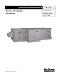
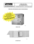
1
BPIII Harsh Environment UPS 50–75 kVA INSTALLATION & OPERATION MANUAL www.powerware.com -------------------------------------------------------------------------------------------------------------------------------------------------------------------------------- IMPORTANT SAFETY INSTRUCTIONS Instructions Importantes Concernant La Sécurité SAVE THESE INSTRUCTIONS Conserver Ces Instructions This manual contains important instructions for your Uninterruptible Power Supply (UPS) system. You should follow these instructions during the installation and maintenance of the UPS, options, accessories, and batteries. Cette notice contient des instructions importantes concernant la sécurité. This equipment has been tested and found to comply with the limits for a Class A digital device, pursuant to Part 15 of the FCC Rules. These limits are designed to provide reasonable protection against harmful interference when the equipment is operated in a commercial environment. This equipment generates, uses, and can radiate radio frequency energy and, if not installed and used in accordance with the instruction manual, may cause harmful interference to radio communications. Operation of this equipment in a residential area is likely to cause harmful interference in which case the user will be required to correct the interference at their own expense. ii Powerware BPIII Harsh Environment UPS 50--75 kV Installation and Operation 164291261 Rev. F 111503 Table of Contents Introduction . . . . . . . . . . . . . . . . . . . . . . . . . . . . . . . . . . . . . . . . . . . . . . . . . . . . . . . . 1 Using This Manual . . . . . . . . . . . . . . . . . . . . . . . . . . . . . . . . . . . . . . . . . . . . Conventions Used in This Manual . . . . . . . . . . . . . . . . . . . . . . . . . . . . . . Safety Considerations . . . . . . . . . . . . . . . . . . . . . . . . . . . . . . . . . . . . . . . . . Getting Help . . . . . . . . . . . . . . . . . . . . . . . . . . . . . . . . . . . . . . . . . . . . . . . . . 3 4 5 5 Section I Installation . . . . . . . . . . . . . . . . . . . . . . . . . . . . . . . . . . . . . . . . . . . . . . . 7 1 Getting Started . . . . . . . . . . . . . . . . . . . . . . . . . . . . . . . . . . . . . . . . . 9 Creating an Installation Plan . . . . . . . . . . . . . . . . . . . . . . . . . . . . . . . . . . . Preparing Your Site . . . . . . . . . . . . . . . . . . . . . . . . . . . . . . . . . . . . . . . . . . . Environmental Considerations . . . . . . . . . . . . . . . . . . . . . . . . . . . . . . . . . Inspecting and Unpacking Each Cabinet . . . . . . . . . . . . . . . . . . . . . . . . Unloading the UPS System From the Pallet . . . . . . . . . . . . . . . . . . . . . . Wiring Requirements . . . . . . . . . . . . . . . . . . . . . . . . . . . . . . . . . . . . . . . . . . 9 9 10 10 11 12 2 Installing the Harsh Environment UPS System . . . . . . . . . . . . 13 Installing the UPS Cabinet Sections . . . . . . . . . . . . . . . . . . . . . . . . . . . . . Grounding Joined Cabinets . . . . . . . . . . . . . . . . . . . . . . . . . . . . . . . . . . . . Installing UPS Internal Power and Control Wiring . . . . . . . . . . . . . . . . . Installing UPS External Wiring . . . . . . . . . . . . . . . . . . . . . . . . . . . . . . . . . . Preparing the UPS for Installing Optional Accessories . . . . . . . . . . . . . Initial Startup . . . . . . . . . . . . . . . . . . . . . . . . . . . . . . . . . . . . . . . . . . . . . . . . . Completing the Installation Checklist . . . . . . . . . . . . . . . . . . . . . . . . . . . . Installation Checklist . . . . . . . . . . . . . . . . . . . . . . . . . . . . . . . . . . . . . . . . . . 14 15 16 17 17 17 18 19 3 Installing a Remote EPO Control . . . . . . . . . . . . . . . . . . . . . . . . . 21 4 Installing a Remote Monitor Panel . . . . . . . . . . . . . . . . . . . . . . . 23 5 Installing a Relay Interface Module . . . . . . . . . . . . . . . . . . . . . . 29 6 Installing a Supervisory Contact . . . . . . . . . . . . . . . . . . . . . . . . . 33 Powerware BPIII Harsh Environment UPS 50--75 kVA Installation and Operation 164201261 Rev. F 111503 iii Section II Operation . . . . . . . . . . . . . . . . . . . . . . . . . . . . . . . . . . . . . . . . . . . . . . 37 iv 7 Understanding UPS Operation . . . . . . . . . . . . . . . . . . . . . . . . . . . 39 Looking Inside the UPS . . . . . . . . . . . . . . . . . . . . . . . . . . . . . . . . . . . . . . . Normal Mode . . . . . . . . . . . . . . . . . . . . . . . . . . . . . . . . . . . . . . . . . . . . . . . . Bypass Mode . . . . . . . . . . . . . . . . . . . . . . . . . . . . . . . . . . . . . . . . . . . . . . . . Battery Mode . . . . . . . . . . . . . . . . . . . . . . . . . . . . . . . . . . . . . . . . . . . . . . . . Maintenance Bypass Mode . . . . . . . . . . . . . . . . . . . . . . . . . . . . . . . . . . . . Monitoring and Controlling UPS Operation . . . . . . . . . . . . . . . . . . . . . . 40 41 42 43 44 45 8 Controls and Features . . . . . . . . . . . . . . . . . . . . . . . . . . . . . . . . . . 47 UPS Controls . . . . . . . . . . . . . . . . . . . . . . . . . . . . . . . . . . . . . . . . . . . . . . . . Monitor Panel . . . . . . . . . . . . . . . . . . . . . . . . . . . . . . . . . . . . . . . . . . . . . Control Panel . . . . . . . . . . . . . . . . . . . . . . . . . . . . . . . . . . . . . . . . . . . . . Maintenance Bypass . . . . . . . . . . . . . . . . . . . . . . . . . . . . . . . . . . . . . . UPS Standard Features . . . . . . . . . . . . . . . . . . . . . . . . . . . . . . . . . . . . . . . Communication Panel . . . . . . . . . . . . . . . . . . . . . . . . . . . . . . . . . . . . . Input Filter . . . . . . . . . . . . . . . . . . . . . . . . . . . . . . . . . . . . . . . . . . . . . . . . Emergency Power Off . . . . . . . . . . . . . . . . . . . . . . . . . . . . . . . . . . . . . . Automatic Battery Charge Current Limit . . . . . . . . . . . . . . . . . . . . . . Installation Features . . . . . . . . . . . . . . . . . . . . . . . . . . . . . . . . . . . . . . . Options and Accessories . . . . . . . . . . . . . . . . . . . . . . . . . . . . . . . . . . . . . . Remote Monitor Panel . . . . . . . . . . . . . . . . . . . . . . . . . . . . . . . . . . . . . Relay Interface Module . . . . . . . . . . . . . . . . . . . . . . . . . . . . . . . . . . . . . Supervisory Contact Module . . . . . . . . . . . . . . . . . . . . . . . . . . . . . . . . Modem . . . . . . . . . . . . . . . . . . . . . . . . . . . . . . . . . . . . . . . . . . . . . . . . . . Customer Convenience Outlet . . . . . . . . . . . . . . . . . . . . . . . . . . . . . . Safety Considerations . . . . . . . . . . . . . . . . . . . . . . . . . . . . . . . . . . . . . . . . . Symbols, Controls, and Indicators . . . . . . . . . . . . . . . . . . . . . . . . . . . . . . 47 47 47 47 47 47 47 48 48 48 48 48 48 48 48 48 49 50 9 Using the Monitor Panel . . . . . . . . . . . . . . . . . . . . . . . . . . . . . . . . . 51 Using the LCD Screen . . . . . . . . . . . . . . . . . . . . . . . . . . . . . . . . . . . . . . . . Using the Pushbuttons . . . . . . . . . . . . . . . . . . . . . . . . . . . . . . . . . . . . . . . . Adjusting the Contrast . . . . . . . . . . . . . . . . . . . . . . . . . . . . . . . . . . . . . . . . Reading the Status Indicators . . . . . . . . . . . . . . . . . . . . . . . . . . . . . . . . . . Using the Menu Options . . . . . . . . . . . . . . . . . . . . . . . . . . . . . . . . . . . . . . . 52 53 53 54 55 Powerware BPIII Harsh Environment UPS 50--75 kV Installation and Operation 164291261 Rev. F 111503 10 Operating the UPS . . . . . . . . . . . . . . . . . . . . . . . . . . . . . . . . . . . . 63 Using the Operating Controls . . . . . . . . . . . . . . . . . . . . . . . . . . . . . . . . . . Operation . . . . . . . . . . . . . . . . . . . . . . . . . . . . . . . . . . . . . . . . . . . . . . . . . . . To Place the UPS in Normal Mode . . . . . . . . . . . . . . . . . . . . . . . . . . . To Shut Down the UPS from Normal Mode . . . . . . . . . . . . . . . . . . . To Start the UPS in Bypass Mode . . . . . . . . . . . . . . . . . . . . . . . . . . . To Transfer the Critical Load to Maintenance Bypass from UPS Bypass.. . . . . . . . . . . . . . . . . . . . . . . . . . . . . . . . . . . . . . . . . . To Transfer the Critical Load to UPS Bypass from Maintenance Bypass.. . . . . . . . . . . . . . . . . . . . . . . . . . . . . . . . . . . To Cold Start the UPS from Battery (No AC Input Power) . . . . . . . To Shut Down the UPS from Cold Start . . . . . . . . . . . . . . . . . . . . . . To Reset the DC to DC Converter . . . . . . . . . . . . . . . . . . . . . . . . . . . Using the EMERGENCY POWER OFF Pushbutton . . . . . . . . . . . . . . . . To use the EMERGENCY POWER OFF Pushbutton . . . . . . . . . . . . Resetting the UPS System after Emergency Power Off . . . . . . . . . 64 66 66 66 67 67 68 69 69 70 70 70 11 Using Features and Options . . . . . . . . . . . . . . . . . . . . . . . . . . . . 71 Building Alarm Monitoring . . . . . . . . . . . . . . . . . . . . . . . . . . . . . . . . . . . . . Summary Alarm Contacts . . . . . . . . . . . . . . . . . . . . . . . . . . . . . . . . . . . . . Remote Monitor Panel . . . . . . . . . . . . . . . . . . . . . . . . . . . . . . . . . . . . . . . . Relay Interface Module . . . . . . . . . . . . . . . . . . . . . . . . . . . . . . . . . . . . . . . . Supervisory Contact Module . . . . . . . . . . . . . . . . . . . . . . . . . . . . . . . . . . . 71 72 73 75 76 12 Responding to System Events . . . . . . . . . . . . . . . . . . . . . . . . . . 77 System Event Horns . . . . . . . . . . . . . . . . . . . . . . . . . . . . . . . . . . . . . . . . . . System Event Lights . . . . . . . . . . . . . . . . . . . . . . . . . . . . . . . . . . . . . . . . . . System Event Messages . . . . . . . . . . . . . . . . . . . . . . . . . . . . . . . . . . . . . . 77 77 78 13 Serial Communications . . . . . . . . . . . . . . . . . . . . . . . . . . . . . . . . 85 Locating the Communications Panel . . . . . . . . . . . . . . . . . . . . . . . . . . . . Connecting Equipment to a Serial Port . . . . . . . . . . . . . . . . . . . . . . . . . . Configuring the Serial Ports . . . . . . . . . . . . . . . . . . . . . . . . . . . . . . . . . . . . Mode . . . . . . . . . . . . . . . . . . . . . . . . . . . . . . . . . . . . . . . . . . . . . . . . . . . . Rate . . . . . . . . . . . . . . . . . . . . . . . . . . . . . . . . . . . . . . . . . . . . . . . . . . . . . Data/Stop . . . . . . . . . . . . . . . . . . . . . . . . . . . . . . . . . . . . . . . . . . . . . . . . Handshaking . . . . . . . . . . . . . . . . . . . . . . . . . . . . . . . . . . . . . . . . . . . . . Disabled (No Handshaking) . . . . . . . . . . . . . . . . . . . . . . . . . . . . . . . . XON/XOFF . . . . . . . . . . . . . . . . . . . . . . . . . . . . . . . . . . . . . . . . . . . . . . . Save . . . . . . . . . . . . . . . . . . . . . . . . . . . . . . . . . . . . . . . . . . . . . . . . . . . . . Default Settings . . . . . . . . . . . . . . . . . . . . . . . . . . . . . . . . . . . . . . . . . . . Terminal Mode . . . . . . . . . . . . . . . . . . . . . . . . . . . . . . . . . . . . . . . . . . . . . . . Printing Selected Information . . . . . . . . . . . . . . . . . . . . . . . . . . . . . . . Entire Log (Ctrl + P) . . . . . . . . . . . . . . . . . . . . . . . . . . . . . . . . . . . . . . . 86 87 89 90 90 91 91 91 91 91 91 92 92 93 Powerware BPIII Harsh Environment UPS 50--75 kVA Installation and Operation 164201261 Rev. F 111503 67 v Meters Printout (Ctrl + M) . . . . . . . . . . . . . . . . . . . . . . . . . . . . . . . . . . System Information Printout (Ctrl + A) . . . . . . . . . . . . . . . . . . . . . . . Battery Test Printout (Ctrl + B) . . . . . . . . . . . . . . . . . . . . . . . . . . . . . . System Configuration . . . . . . . . . . . . . . . . . . . . . . . . . . . . . . . . . . . . . . . . . System Configuration Mode Main Menu . . . . . . . . . . . . . . . . . . . . . . Program Building Alarms . . . . . . . . . . . . . . . . . . . . . . . . . . . . . . . . . . . Enable/Disable Default Functions . . . . . . . . . . . . . . . . . . . . . . . . . . . Customize Alarm Messages . . . . . . . . . . . . . . . . . . . . . . . . . . . . . . . . Program Unit Name . . . . . . . . . . . . . . . . . . . . . . . . . . . . . . . . . . . . . . . Adjust Output Voltage . . . . . . . . . . . . . . . . . . . . . . . . . . . . . . . . . . . . . Change Password . . . . . . . . . . . . . . . . . . . . . . . . . . . . . . . . . . . . . . . . . Battery Test Setup . . . . . . . . . . . . . . . . . . . . . . . . . . . . . . . . . . . . . . . . . Modify Low Battery Time . . . . . . . . . . . . . . . . . . . . . . . . . . . . . . . . . . . Calibration Mode . . . . . . . . . . . . . . . . . . . . . . . . . . . . . . . . . . . . . . . . . . . . . Computer Mode . . . . . . . . . . . . . . . . . . . . . . . . . . . . . . . . . . . . . . . . . . . . . . Remote Monitor Mode . . . . . . . . . . . . . . . . . . . . . . . . . . . . . . . . . . . . . . . . 94 94 95 96 96 96 97 98 98 99 99 100 101 101 101 101 14 Remote Notification . . . . . . . . . . . . . . . . . . . . . . . . . . . . . . . . . . . 103 Remote Notification Features . . . . . . . . . . . . . . . . . . . . . . . . . . . . . . . . . . Description of Operation . . . . . . . . . . . . . . . . . . . . . . . . . . . . . . . . . . . . . . Call Answer . . . . . . . . . . . . . . . . . . . . . . . . . . . . . . . . . . . . . . . . . . . . . . Call Out . . . . . . . . . . . . . . . . . . . . . . . . . . . . . . . . . . . . . . . . . . . . . . . . . . Housekeeping . . . . . . . . . . . . . . . . . . . . . . . . . . . . . . . . . . . . . . . . . . . . Hardware Requirements . . . . . . . . . . . . . . . . . . . . . . . . . . . . . . . . . . . . . . . Configuring the Modem . . . . . . . . . . . . . . . . . . . . . . . . . . . . . . . . . . . . . . . Basic Modem Configuration . . . . . . . . . . . . . . . . . . . . . . . . . . . . . . . . Configuring the Modem to Call a Remote Computer . . . . . . . . . . . Configuring the Modem to Call a Numeric Pager . . . . . . . . . . . . . . Configuring the Modem to Answer Incoming Calls . . . . . . . . . . . . . Final Modem Configuration . . . . . . . . . . . . . . . . . . . . . . . . . . . . . . . . . UPS Setup Configuration . . . . . . . . . . . . . . . . . . . . . . . . . . . . . . . . . . . . . . User-Selected Events . . . . . . . . . . . . . . . . . . . . . . . . . . . . . . . . . . . . . . . . . 104 105 105 105 106 107 108 108 109 110 111 111 112 113 15 Maintaining the UPS System . . . . . . . . . . . . . . . . . . . . . . . . . . . 117 Important Safety Instructions . . . . . . . . . . . . . . . . . . . . . . . . . . . . . . . . . . . Performing Preventive Maintenance . . . . . . . . . . . . . . . . . . . . . . . . . . . . . Maintenance Training . . . . . . . . . . . . . . . . . . . . . . . . . . . . . . . . . . . . . . . . . 117 118 119 16 Product Specifications . . . . . . . . . . . . . . . . . . . . . . . . . . . . . . . . . 121 System Input . . . . . . . . . . . . . . . . . . . . . . . . . . . . . . . . . . . . . . . . . . . . . . . . System Output . . . . . . . . . . . . . . . . . . . . . . . . . . . . . . . . . . . . . . . . . . . . . . . Environmental Specifications . . . . . . . . . . . . . . . . . . . . . . . . . . . . . . . . . . Battery Specifications . . . . . . . . . . . . . . . . . . . . . . . . . . . . . . . . . . . . . . . . . 121 122 123 123 Appendix A . . . . . . . . . . . . . . . . . . . . . . . . . . . . . . . . . . . . . . . . . . . . . . . . . . . . . . . A---1 vi Powerware BPIII Harsh Environment UPS 50--75 kV Installation and Operation 164291261 Rev. F 111503 List of Figures Figure 1. Powerware BPIII Harsh Environment UPS System . . . . . . . . . 2 Figure 2. Cabinet as Shipped, with Outer Packaging and Pallet . . . . . . 10 Figure 3. Removing Front and Rear Supports . . . . . . . . . . . . . . . . . . . . . . 12 Figure 4. UPS and Environmental Cabinets . . . . . . . . . . . . . . . . . . . . . . . . 13 Figure 5. Cabinet-to-Cabinet Grounding . . . . . . . . . . . . . . . . . . . . . . . . . . 15 Figure 6. Remote EPO Control . . . . . . . . . . . . . . . . . . . . . . . . . . . . . . . . . . . 21 Figure 7. Remote Monitor Panel (RMP) . . . . . . . . . . . . . . . . . . . . . . . . . . . 24 Figure 8. Terminal Block Bracket . . . . . . . . . . . . . . . . . . . . . . . . . . . . . . . . . 25 Figure 9. Wiring an RMP to the UPS . . . . . . . . . . . . . . . . . . . . . . . . . . . . . . 26 Figure 10. Relay Interface Module . . . . . . . . . . . . . . . . . . . . . . . . . . . . . . . . . 29 Figure 11. Terminal Block Bracket . . . . . . . . . . . . . . . . . . . . . . . . . . . . . . . . . 30 Figure 12. Wiring an RIM to the UPS . . . . . . . . . . . . . . . . . . . . . . . . . . . . . . . 31 Figure 13. Supervisory Contact Module . . . . . . . . . . . . . . . . . . . . . . . . . . . . 33 Figure 14. Terminal Block Bracket . . . . . . . . . . . . . . . . . . . . . . . . . . . . . . . . . 34 Figure 15. Wiring an SCM to the UPS . . . . . . . . . . . . . . . . . . . . . . . . . . . . . . 35 Figure 16. Supervisory Contact Module TB2 . . . . . . . . . . . . . . . . . . . . . . . . 36 Figure 17. Main Elements of the UPS System . . . . . . . . . . . . . . . . . . . . . . . 40 Figure 18. Path of Current Through the UPS in Normal Mode . . . . . . . . . 41 Figure 19. Path of Current Through the UPS in Bypass Mode . . . . . . . . . 42 Figure 20. Path of Current Through the UPS in Battery Mode . . . . . . . . . 43 Figure 21. Path of Current Through the UPS in Maintenance Bypass Mode . . . . . . . . . . . . . . . . . . . . . . . . . . . . . . . . . . . . . . . . . 44 Figure 22. Location of the Monitor Panel and the Control Panel . . . . . . . 45 Figure 23. UPS Monitor Panel . . . . . . . . . . . . . . . . . . . . . . . . . . . . . . . . . . . . 51 Figure 24. Parts of the LCD Screen (Typical for Powerware BPIII HE 75 480/480V Unit) . . . . . . . . . 52 Powerware BPIII Harsh Environment UPS 50--75 kVA Installation and Operation 164201261 Rev. F 111503 vii viii Figure 25. System Meters Screen (Typical for Powerware BPIII HE 75 480/480V Unit) . . . . . . . . . 55 Figure 26. Load Amps Meters Screen . . . . . . . . . . . . . . . . . . . . . . . . . . . . . . 56 Figure 27. Event History Log Screen . . . . . . . . . . . . . . . . . . . . . . . . . . . . . . . 57 Figure 28. Active System Events Screen . . . . . . . . . . . . . . . . . . . . . . . . . . . 58 Figure 29. Unit Statistics Screen . . . . . . . . . . . . . . . . . . . . . . . . . . . . . . . . . . 59 Figure 30. Mimic Screen . . . . . . . . . . . . . . . . . . . . . . . . . . . . . . . . . . . . . . . . . 60 Figure 31. Time Setup Screen . . . . . . . . . . . . . . . . . . . . . . . . . . . . . . . . . . . . 61 Figure 32. Port Setup Screen . . . . . . . . . . . . . . . . . . . . . . . . . . . . . . . . . . . . . 62 Figure 33. Location of the Operating Controls . . . . . . . . . . . . . . . . . . . . . . 63 Figure 34. UPS Control Panel . . . . . . . . . . . . . . . . . . . . . . . . . . . . . . . . . . . . . 64 Figure 35. External Connections for Building Alarm Monitoring . . . . . . . . 71 Figure 36. Summary Alarm Contacts . . . . . . . . . . . . . . . . . . . . . . . . . . . . . . 72 Figure 37. Remote Monitor Panel . . . . . . . . . . . . . . . . . . . . . . . . . . . . . . . . . 73 Figure 38. Relay Interface Module . . . . . . . . . . . . . . . . . . . . . . . . . . . . . . . . . 74 Figure 39. Supervisory Contact Module . . . . . . . . . . . . . . . . . . . . . . . . . . . . 76 Figure 40. Location of Communications Ports on the Powerware BPIII HE UPS (shown without the Environmental Cabinet) . . . . . . 86 Figure 41. Port 1 Pin Assignments . . . . . . . . . . . . . . . . . . . . . . . . . . . . . . . . . 87 Figure 42. Port 2 Pin Assignments . . . . . . . . . . . . . . . . . . . . . . . . . . . . . . . . . 88 Figure 43. Setup Serial Port 1 Screen . . . . . . . . . . . . . . . . . . . . . . . . . . . . . . 89 Figure 44. Event History Log . . . . . . . . . . . . . . . . . . . . . . . . . . . . . . . . . . . . . 93 Figure 45. System Meters . . . . . . . . . . . . . . . . . . . . . . . . . . . . . . . . . . . . . . . . 94 Figure 46. Battery Test Log . . . . . . . . . . . . . . . . . . . . . . . . . . . . . . . . . . . . . . . 95 Powerware BPIII Harsh Environment UPS 50--75 kV Installation and Operation 164291261 Rev. F 111503 Introduction Powerware BPIII online power protection can be utilized to prevent loss of valuable electronic information, minimize equipment downtime, and/or minimize the adverse effect on equipment production due to unexpected power problems. The Powerware BPIII Harsh Environment (HE) Uninterruptible Power Supply (UPS) system continually monitors incoming electrical power and removes the surges, spikes, sags, and other irregularities that are inherent in commercial utility power. Working with the electrical system, the UPS supplies clean, consistent power that sensitive electronic equipment requires for reliable operation. During brownouts, blackouts, and other power interruptions, one or more optional battery cabinets can provide emergency power to safeguard your operation. The UPS will function automatically and requires very little attention during normal operation. However, read and understand the procedures described in this manual to ensure trouble-free operation. This manual describes how to install and operate the Powerware BPIII HE Uninterruptible Power Supply (UPS) system. It contains instructions for installing and operating both the UPS and Environmental cabinets. Each component of the Harsh Environment UPS system is housed in a free-standing cabinet. The system configuration consists of the UPS and the Environmental cabinets. Figure 1 shows the Powerware BPIII Harsh Environment UPS system. Powerware BPIII Harsh Environment UPS 50--75 kVA Installation and Operation 164201261 Rev. F 111503 1 UPS CABINET ENVIRONMENTAL CABINET Figure 1. Powerware BPIII Harsh Environment UPS System 2 Powerware BPIII Harsh Environment UPS 50--75 kV Installation and Operation 164291261 Rev. F 111503 Using This Manual This manual describes the Powerware BPIII HE UPS installation, operation and routine maintenance. The information in this manual is divided into the sections and chapters listed. Introduction The Introduction provides a brief description of the UPS system, a description of the content of each chapter, safety, text conventions used in the manual and reference information. Section I -- Installation • Chapter 1 -- Getting Started -- tells you how to prepare your site for the installation of your UPS system. It discusses equipment environmental requirements, inspecting, and unpacking cabinets. • Chapter 2 -- Installing the Harsh Environment UPS System -- describes how to install the UPS system. • Chapter 3 -- Installing a Remote EPO Control -- discusses installing the optional Remote Emergency Power Off (EPO) control. • Chapter 4 -- Installing a Remote Monitor Panel -- contains information for installing the optional Remote Monitor Panel (RMP). • Chapter 5 -- Installing a Relay Interface Module -- contains information for installing the optional Relay Interface Module (RIM). • Chapter 6 -- Installing a Supervisory Contact Module -- contains information for installing the optional Supervisory Contact Module (SCM). Section II -- Operation • Chapter 7 -- Understanding UPS Operation -- provides information on understanding the operation UPS. • Chapter 8 -- Controls and Features -- describes the standard features and controls of the UPS system. • Chapter 9 -- Using the Monitor Panel -- describes the controls and indicators found on the Monitor Panel and shows the various information screens displayed on the LCD screen. • Chapter 10 -- Operating the UPS -- contains startup and shutdown procedures for the UPS system. • Chapter 11 -- Using Features and Options -- contains descriptions and instructions for the UPS system features and options. • Chapter 12 -- Responding to System Events -- lists all the alarm, messages and notices that occur during operation of the UPS system. Powerware BPIII Harsh Environment UPS 50--75 kVA Installation and Operation 164201261 Rev. F 111503 3 • Chapter 13 -- Serial Communications -- describes the serial communications features of the UPS system. • Chapter 14 -- Remote Notification -- contains instructions for using the remote notification feature of the UPS system. • Chapter 15 -- Maintaining the UPS System -- contains maintenance instructions for the UPS system. • Chapter 16 -- Product Specifications -- provides detailed specifications for the UPS system. • Appendix A -- Customer Information -- contains important information on wiring requirements and recommendations, and important diagrams of the cabinet’s mechanical details and electrical access. Read through each procedure before you begin. Conventions Used in This Manual The text in this manual uses these conventions: • Bold type highlights important concepts in discussions, key terms in procedures, and menu options. • Rectangular boxes containing bold type are warnings or cautions that pertain to the UPS system or its electrical connections. This important information alerts you to possible dangers pertaining to personnel safety, UPS or equipment damage, critical load protection, or operational concerns. • Italic type highlights notes and new terms where they are defined. In this manual, the term UPS or UPS system refers to the UPS cabinet and its internal elements and the environmental cabinet. The rectifier and inverter are internal UPS components that are together referred to as the power processing unit (PPU) of the UPS. 4 Powerware BPIII Harsh Environment UPS 50--75 kV Installation and Operation 164291261 Rev. F 111503 Safety Considerations The UPS and Environmental cabinets are designed for industrial applications in harsh environments. However, the UPS system is a sophisticated power system and should be handled with appropriate care, following these guidelines: • Keep surroundings clean and free from excess moisture. • Do not operate the UPS system close to gas or electric heat sources. • The system is not intended for outdoor use. • The operating environment should be maintained within the parameters stated in this manual. • Keep the cabinet doors closed to ensure proper cooling airflow and to protect personnel from dangerous voltages inside the unit. • The system contains its own power source. Lethal voltages are present even when the UPS is disconnected from utility power. WARNING: Only AUTHORIZED SERVICE PERSONNEL should perform service or maintenance on the parallel redundant system. If service or routine maintenance is required: • Ensure all power is disconnected before performing installation or service. • Ensure the area around the UPS system is clean and uncluttered. • Observe all DANGER, CAUTION, and WARNING notices affixed to the inside and outside of the equipment. Getting Help If you need to schedule initial startup, need regional locations and telephone numbers, have a question about any of the information in this manual, or have a question this manual does not answer, please call Powerware at: United States Canada Outside the U.S. 1-800-843-9433 1-800-461-9166 Call your local representative Powerware BPIII Harsh Environment UPS 50--75 kVA Installation and Operation 164201261 Rev. F 111503 5 This Page Intentionally Left Blank. 6 Powerware BPIII Harsh Environment UPS 50--75 kV Installation and Operation 164291261 Rev. F 111503 Section I Installation Powerware BPIII Harsh Environment UPS 50--75 kVA Installation and Operation 164201261 Rev. F 111503 7 This Page Intentionally Left Blank. 8 Powerware BPIII Harsh Environment UPS 50--75 kV Installation and Operation 164291261 Rev. F 111503 Getting Started The Harsh Environment (HE) UPS system is shipped as two separate cabinets (UPS Cabinet and Environmental Cabinet). Each cabinet is shipped on a wood/foam and steel pallet. Use a forklift or pallet jack to move the packaged cabinets to the installation site, or as close as possible to the site, before unloading from the pallets. This is the basic sequence of the installation steps: 1. Create an installation plan for the UPS and Environmental cabinets. 1. Prepare your site for the UPS system. 2. Inspect, unpack, and unload the cabinets. 3. Wire the cabinets as applicable (Chapter 2). 4. Complete the Installation Checklist (Chapter 2). 5. Have authorized service personnel perform preliminary checks and startup. After wiring the UPS system to the facility power and critical load(s), be sure to ground the system according to local and/or national electrical wiring codes, using your own cabling and conduit. NOTE: Startup and operational checks should be performed only by authorized service personnel. This service is usually offered as part of the sales contract for your UPS system. Creating an Installation Plan Before beginning to install your UPS system, you should be sure you understand the instructions in this manual. Use the procedures and illustrations in the following sections to create a logical plan for installing the UPS system The information in this chapter and Chapter 2 will help you plan the installation. Preparing Your Site For your UPS system to operate at peak efficiency, your installation site should meet the environmental parameters outlined in this manual. If you intend to operate the UPS at an altitude higher than 1500 meters (5000 feet), contact your local sales or service office for important information about high altitude operation. The operating environment must meet the size and weight requirements shown in Table J of Appendix A. The basic environmental requirements for operation of the UPS system are: Ambient Temperature Range: 0---50˚ C (32---122˚ F) Recommended Operating Range: 20---25˚ C (68---77˚ F) Maximum Relative Humidity: 95% The UPS and Environmental cabinets use forced air cooling to regulate internal component temperature. Air inlets are on the right side of the Environmental Cabinet and outlets are on the top of the UPS cabinet. You must allow clearance in front of and above each cabinet for proper air circulation. Powerware BPIII Harsh Environment UPS 50--75 kVA Installation and Operation 164201261 Rev. F 111503 9 Environment Considerations The UPS system must be installed on a sealed concrete floor. WARNING: Installation should be performed by qualified personnel. Inspecting and Unpacking Each Cabinet The first task in preparing for installation is inspecting and unpacking each cabinet. Cabinets arrive covered with protective packaging material as shown in Figure 2. OUTER PACKAGING FOAM CUSHION Figure 2. Cabinet as Shipped, with Outer Packaging and Pallet 1. Carefully inspect the outer packaging for evidence of damage during transit. CAUTION: Do not install a damaged cabinet. Report any damage to the carrier and contact your local sales or service office immediately. 10 Powerware BPIII Harsh Environment UPS 50--75 kV Installation and Operation 164291261 Rev. F 111503 2. Use a forklift or other material handling equipment to move the cabinets to a convenient unpacking area. Insert the forklift jacks between the foam cushions on the bottom of the unit. CAUTION: DO NOT tilt cabinets more than 10 degrees from vertical. 3. Set each pallet on a firm, level surface, allowing a minimum clearance of 4.6m (15 ft) on each side for removing the cabinets from the pallets. 4. Cut the steel bands around each cabinet. 5. Remove the protective cardboard covering from the cabinets, cutting where indicated, using a knife blade no longer than 25 mm (1 in.). NOTE: Do not discard the packaging material yet. Instructions for unloading the cabinet from the pallet are printed on the cardboard, and you will need to refer to them. 6. Remove the plastic bag and foam packing material, and discard or recycle them in a responsible manner. Unloading the UPS System From the Pallet The UPS and Environmental cabinets are each bolted to sheet metal pallets consisting of four supports secured to foam cushions. The foam cushions act as shock absorbers for the cabinet during shipment. WARNING: UPS cabinets are extremely heavy. If unloading instructions are not closely followed, the cabinet may tip and cause serious injury. Turning the jacking bolts unevenly may cause the cabinet to become unbalanced. To prevent tipping, raise and lower the jacking bolts evenly. The cabinet should only be raised approximately 3 mm (1/8 in.) above the floor (just enough to remove foam cushions). 1. Starting with the UPS cabinet, open and remove the cabinet door. Remove the retaining screw located inside the door at the bottom hinge pivot point, then lift the door off. Save the retaining screws for reinstallation of the door. 2. Locate the field kit (packed inside of the cabinet or communication panel). Locate the four ½-in. jacking bolts and install them in the threaded holes in the front and rear supports. Place a floor protector underneath each jacking bolt, and screw the bolts down against them. The floor protectors will save the floor from being marred by the jacking bolts. 3. Loosen, but do not remove the hardware holding the foam cushions to the front and rear supports (labeled “1” in Figure 3). 4. Turn each jacking bolt consecutively, two full turns, until the foam cushions clear the floor by approximately 3 mm (1/8 in.). 5. After the foam cushions clear the floor, remove the hardware loosened in step 3. Pull the foam cushions out from under the cabinet, and discard or recycle them in a responsible manner. Powerware BPIII Harsh Environment UPS 50--75 kVA Installation and Operation 164201261 Rev. F 111503 11 DOOR FRONT SUPPORT 2 FOAM CUSHION SIDE SUPPORT 1 FLOOR PROTECTOR 2 2 2 1 JACKING BOLT 2 1 Figure 3. Removing Front and Rear Supports WARNING: Cabinet may fall. Do not loosen hardware attaching the side or front supports to cabinet base. Also, do not loosen supports from each other. The cabinet must be lowered using jacking bolts before supports can be removed. 6. Carefully and evenly lower the cabinet by turning each jacking bolt consecutively two full turns (maximum) until the supports contact the floor, and the cabinet is no longer supported by the jacking bolts. 7. After the cabinet is resting on the floor, remove the jacking bolts and discard or recycle them in a responsible manner. 8. Remove the hardware labeled “2” in Figure 3, holding the front, rear and side supports to the cabinet base. Discard or recycle the hardware and support brackets in a responsible manner. 9. Replace the door that was removed in step 1. The cabinet is now ready to be rolled to its final location. 10. Repeat steps 1 through 9 for the Environmental cabinet. Wiring Requirements For external wiring requirements, including the minimum AWG size of external wiring, see Tables A and E of Appendix A. The power wiring for this equipment is rated at 90˚C. 12 Powerware BPIII Harsh Environment UPS 50--75 kV Installation and Operation 164291261 Rev. F 111503 Installing the Harsh Environment UPS System After the UPS system is unpacked and moved to the final installation location, the UPS and Environmental Cabinets are ready to be joined. Once the cabinets are joined, internal and external wiring is installed. Figure 4 shows the UPS and Environmental cabinets assembled. The top view shows the cable entry plate in the Environmental cabinet. TOP VIEW FRONT VIEW Figure 4. UPS and Environmental Cabinets Powerware BPIII Harsh Environment UPS 50--75 kVA Installation and Operation 164201261 Rev. F 111503 13 WARNING: Installation should be performed by qualified personnel. Note the following important information while installing the UPS: • Dimensions in this manual are provided in millimeters and inches. • Do not tilt the UPS or other cabinets more than 10˚ during installation. • Cooling exhaust airflow is approximately 614.0 L/S (1300 CFM). • The conduit landing plate is to be removed to add conduit landing holes as required. Plate material is 16 gauge steel (0.06 in. thick). • Terminals E9 through E15 and E19–E35 are UL and CSA rated at 90˚C. A hex key tool is required to attach wires to the terminals. • Details about control wiring are provided in each procedure for connecting options and features. Table L in Appendix A identifies the control wiring terminations. Installing the UPS Cabinet Sections 1. Move the UPS and Environmental cabinets together, placing the UPS cabinet on the left side of the Environmental Cabinet. 2. Secure the UPS and Environmental cabinets with the leveling feet provide on each cabinet. 3. Locate the field kit and remove cabinet joining brackets and hardware from the kit. 4. Install the brackets to the front and rear of each cabinet base, using the threaded holes provided. Brackets should be mounted so that the tabs at end of the brackets meet between the two cabinets. 5. Install bolts through the tabs at front and back and secure with washers and nuts. 6. Secure cabinet sides to each other at the top front and top back with 1/2 inch bolts, washers and nuts from the field kit. Use the holes provide in the cabinet sides. 7. Attach a ground to the joined cabinets using the procedure “Grounding Joined Cabinets” in this chapter. 14 Powerware BPIII Harsh Environment UPS 50--75 kV Installation and Operation 164291261 Rev. F 111503 Grounding Joined Cabinets Open the door of each cabinet. Locate the grounding stud at the front/side of each frame. Remove the top nut, lock washer, and flat washer from each stud (if attached, see Figures 5). 1. Locate the grounding cable (part of the field kit, located in a small bag which is fastened to the UPS cabinet in the customer terminal area). 2. Mount the grounding cable as shown in Figure 5, attaching it to the frame of each cabinet using the hardware previously removed. HARDWARE REMOVED BEFORE PLACING LUG OVER GROUND STUD GROUNDING CABLE FRONT CABINET BASE (side view) PERMANENTLY ATTACHED HARDWARE Figure 5. Cabinet-to-Cabinet Grounding Powerware BPIII Harsh Environment UPS 50--75 kVA Installation and Operation 164201261 Rev. F 111503 15 Installing UPS Internal Power and Control Wiring NOTE: The cables used in steps 2 through 12 are coiled inside the Environmental cabinet and are attached at the factory to the terminals inside this cabinet. Wiring harness with connectors J20, J22, and J23 are coiled inside the UPS cabinet. Wiring harness with connectors P20, P22, and P23 are coiled inside the Environmental cabinet. Refer to Drawings 164201261 ---1 and 164201261 ---4 in Appendix A of this manual for wiring and termination requirements and terminal locations. 1. Remove the sheet metal shield covering the bottom half of the UPS cabinet. 2. Route DC input cables (cables 205 and 206) from the Environmental cabinet through the cutout in cabinet sides to the DC UPS Input terminals in the UPS cabinet. 3. Connect positive DC power cable 205 to the DC input terminal E4. Refer to Appendix A of this manual for terminal locations and tightening torque. 4. Connect negative DC power cable 206 to the DC input terminal E5. Refer to Appendix A of this manual for terminal locations and tightening torque. 5. Route AC Input Bypass Transformer cables (cables 227, 228 and 229) from the Environmental cabinet through the cutout in cabinet sides to the Bypass Transformer Input terminals in the UPS cabinet. 6. Connect phase A, B, and C power wiring cables 227, 228, and 229 to Bypass Transformer Input terminals E13, E14, and E15 respectively. Refer to Appendix A of this manual for terminal locations and tightening torques. 7. Route AC Input to UPS Rectifier cables (cables 250, 251 and 252) from the Environmental cabinet through the cutout in cabinet sides to the UPS Rectifier Input terminals in the UPS cabinet. 8. Connect phase A, B, and C power wiring cables 250, 251, and 252 to AC Input to UPS Rectifier Input terminals E1, E2, and E3 respectively. Refer to Appendix A of this manual for terminal locations and tightening torques. 9. Route AC Output cables (cables 237, 238 and 239) from the Environmental cabinet through the cutout in cabinet sides to the AC Output terminals in the UPS cabinet. 10. Connect phase A, B, and C power wiring cables 237, 238, and 239 to AC Output terminals E9, E10, and E11 respectively. Refer to Appendix A of this manual for terminal locations and tightening torques. 11. Route two Neutral cables (cable 600) from the Environmental cabinet through the cutout in cabinet sides to the Neutral terminal in the UPS cabinet. 12. Connect two Neutral power wiring cables 600 to Neutral terminal E12. Refer to Appendix A of this manual for terminal locations and tightening torques. 13. Route wiring harness with connectors P20, P22, and P23 from the Environmental cabinet through the cutout in cabinet sides. 14. Connect connectors P20, P22, and P23 to connectors J20, J22, and J23 respectively. 15. Reinstall UPS Cabinet sheetmetal shield. 16 Powerware BPIII Harsh Environment UPS 50--75 kV Installation and Operation 164291261 Rev. F 111503 Installing UPS External Wiring 1. Install rectifier, bypass, and battery input power wiring to terminals in the Environmental cabinet. Refer to Drawings 164201261---1 and 164201261---4 in Appendix A of this manual for wiring and termination requirements and terminal locations. 2. Install the critical load output power wiring to terminals in the Environmental cabinet. Refer to Drawings 164201261---1 and 164201261---4 in Appendix A of this manual for wiring and termination requirements and terminal locations. 3. Reinstall cabinet doors. Preparing the UPS for Installing Optional Accessories If you are installing optional accessories, such as a Remot EPO or an RMP, you must prepare the UPS cabinet for the installation of these options. To prepare the UPS for wiring to an RMP, RIM, SCM or Remote EPO: 1. Be sure the UPS is turned off and all power sources are removed. (See the operator’s manual for instructions.) 2. Open the doors of the UPS. 3. Remove the lower sheetmetal shield. Set the shield and hardware aside for later reuse. Initial Startup Startup and operational checks should be performed only by authorized service personnel. Contact service in advance (usually a two week notice is required) to reserve a preferred startup date. Powerware BPIII Harsh Environment UPS 50--75 kVA Installation and Operation 164201261 Rev. F 111503 17 Completing the Installation Checklist The final step in installing the UPS system is completing the following Installation Checklist. This checklist ensures that all hardware, cables, and other equipment have been completely installed . Completing all items on the checklist will ensure a smooth installation. Make a copy of the Installation Checklist before filling it out, and retain the original. After the installation is complete, a service representative will be able to verify the operation of the UPS system and commission it to support the critical load. The service representative cannot perform any installation tasks other than verifying software and operating setup parameters. Service personnel may request a copy of the completed Installation Checklist to be sure you have completed all applicable equipment installation. NOTE: The Installation Checklist MUST be completed prior to starting the UPS system for the first time. 18 Powerware BPIII Harsh Environment UPS 50--75 kV Installation and Operation 164291261 Rev. F 111503 Installation Checklist -All packing materials and restraints have been removed from each cabinet. -Each cabinet in the UPS system is placed in its installed location. -All cabinets are bolted together. -A ground bond is installed between all cabinets that are bolted together. -All switchboards, conduits, and cables are properly routed to the UPS. -Power cables are terminated on AC Input terminals (UPS Cabinet) (E1---E3). -Power cables are terminated on Bypass Transformer input terminals (UPS Cabinet) (E13---E15). -Power cables are terminated on AC Output terminals (UPS Cabinet) (E9---E12). -Power cables are terminated on DC Input terminals (UPS Cabinet) (E4---E5). -Power cables are terminated on bypass terminals (E19---E21). -Power cables are terminated on the CB1 input breaker (E33---E35 ). -Power cables are terminated on output terminals (E25---E27). -A ground conductor is properly installed. -If N is used, no other N---G bonds exist downstream from the UPS. -Battery cables and harness are terminated on the CB2 battery breaker E31 and E32. -The area around the installed UPS system is clean and dust-free. (It is recommended that the UPS be installed on a sealed concrete pad on a sealed concrete floor.) -Adequate workspace exists around the UPS and other cabinets. -Adequate lighting is provided around all UPS equipment. -A 120V service outlet is located within 25 feet of the UPS equipment. Powerware BPIII Harsh Environment UPS 50--75 kVA Installation and Operation 164201261 Rev. F 111503 19 Notes 20 Powerware BPIII Harsh Environment UPS 50--75 kV Installation and Operation 164291261 Rev. F 111503 Installing a Remote EPO Control The Remote EPO control arrives as shown in Figure 6. See Drawing 164201261---7 in Appendix A for enclosure dimensions, side views, and knockout patterns. UNINTERRUPTIBLE POWER SYSTEM EMERGENCY OFF to UPS to other equipment Figure 6. Remote EPO Control To install a Remote EPO control: 1. Securely mount the Remote EPO station. Recommended locations include operator’s consoles or exit doors. 2. Install wiring from the Remote EPO station using ½-in. conduit through the 7/8-in. knockout in either the top or bottom of the UPS. 3. Connect the Remote EPO wiring as shown in Tables A and B: Table A. Remote EPO Wire Terminations From REPO Station(s) To Communications Panel in UPS TB1---4 TB2---1 TB1---5 TB2---2 Remarks Twisted wires (2) 14---18 gauge Powerware BPIII Harsh Environment UPS 50--75 kVA Installation and Operation 164201261 Rev. F 111503 21 Table B. Remote EPO 1 REMOTE EPO SWITCH TB2 2 TWISTED WIRES (2) Remote EPO switch rating is 24 VDC. 1 Amp minimum if supplied by user. NOTE: This switch must be a dedicated switch not tied into any other circuits. 4. If installing multiple Remote EPO stations, wire additional stations in parallel with the first Remote EPO. 5. If required, install ½-in. conduit and wiring from the Remote EPO station to trip circuitry of upstream protective devices. A normally open contact is provided, as shown in Table B. Remote EPO switch wiring must be in accordance with UL Class II requirements. 6. Secure the UPS by reversing all steps taken to prepare it for Remote EPO installation. 22 Powerware BPIII Harsh Environment UPS 50--75 kV Installation and Operation 164291261 Rev. F 111503 Installing a Remote Monitor Panel As an option, a Remote Monitor Panels (RMPs) can be installed to monitor the operation of the UPS system from virtually any location within the facility, up to 500 feet from the UPS. Flush-mount or surface-mount an RMP on a desktop or on a wall, wherever you have a serial interface line. A maximum of two monitoring accessories (RMPs, RIMs, or SCMs) can be installed. See Table C for the number of accessories permitted. Figure 7 shows an RMP. Drawing 164201261---7 in Appendix A shows the enclosure dimensions and knockout patterns. Table C. Optional Monitoring Accessories Number and Type of Accessories Permitted Remote Monitor Panel Relay Interface Panel Supervisory Contact Module 2 — — — 2 — — — 2 1 1 — 1 — 1 — 1 1 Powerware BPIII Harsh Environment UPS 50--75 kVA Installation and Operation 164201261 Rev. F 111503 23 FLUSH MOUNT SURFACE MOUNT (FOR HANGING) WIRES MUST BE TWISTED Figure 7. Remote Monitor Panel (RMP) 24 Powerware BPIII Harsh Environment UPS 50--75 kV Installation and Operation 164291261 Rev. F 111503 Before installing an RMP, be sure you have prepared the UPS according to the instructions in Chapter 2. To install an RMP: 1. Securely mount the RMP(s). 2. Install wiring from the RMP using ½-in. conduit through the cable entry panels in either the top or bottom of the UPS cabinet. The top entry connection requires installation of ½-in. flexible conduit within the UPS. Bottom entry connection requires no additional routing of conduit within the UPS. 3. In the spare parts kit, locate the RMP adapter cable assembly (see Figure 8). Mate the DB---9 connector on the back of the terminal block into the DB---9 connector on the Communications Panel of the UPS (see Figure 9). Use two screws from the spare parts kit to secure the terminal block bracket to the Communications Panel. Connect to Port 1 (DB---9) on Communications Panel FUSE TERMINAL BLOCK (TB3) Figure 8. Terminal Block Bracket Powerware BPIII Harsh Environment UPS 50--75 kVA Installation and Operation 164201261 Rev. F 111503 25 DB---9 CONNECTOR (ON COMMUNICATIONS PANEL OF THE UPS) TB1 TB2 Figure 9. Wiring an RMP to the UPS 4. Connect RMP wiring to the terminal block using terminations shown in Table D. Table D. RMP Wire Terminations 26 From RMP A To UPS TB1---4 TB3---1 TB1---5 TB3---2 TB1---6 TB3---3 TB1---7 TB3---4 From RMP B (if used) To UPS TB1---4 TB3---5 TB1---5 TB3---6 TB1---6 TB3---7 TB1---7 TB3---8 Remarks TWISTED WIRES (4) 1 2 TURNS PER 1---2 3 INCHES Remarks TWISTED WIRES (4) 1 2 TURNS PER 1---2 3 INCHES Powerware BPIII Harsh Environment UPS 50--75 kV Installation and Operation 164291261 Rev. F 111503 5. To check the operation of the RMP, ensure that the UPS is supplying the load via inverter or bypass. If the indicators on the RMP show the appropriate status, then it is operating correctly. If the communications link between the UPS and the RMP is not present, the RMP will self-test (all indicators flash and the horn beeps at one-second intervals). If this occurs, check all harness connectors and the fuse for proper seating. If all connections are secure but the RMP continues to self-test, replace the fuse with the spare included in the hardware kit. If this does not correct the problem, contact your local field service office for verification that the RMP is working correctly. 6. To test the indicator lamps, press the horn silence button and hold it for 3 seconds. All lamps should light, and the horn will sound continuously until you release the button. 7. Repeat steps 1, 2, and 4 through 6 for each RMP you are installing. 8. If you are installing an RIM or SCM in addition to an RMP, proceed to Chapter 5 or 6, respectively; otherwise, secure the UPS cabinet by reversing the steps contained in procedure “To Prepare the UPS for Wiring to an RMP, RIM, SCM, or Remote EPO” of Chapter 2. Powerware BPIII Harsh Environment UPS 50--75 kVA Installation and Operation 164201261 Rev. F 111503 27 This Page Intentionally Left Blank. 28 Powerware BPIII Harsh Environment UPS 50--75 kV Installation and Operation 164291261 Rev. F 111503 Installing a Relay Interface Module The optional Relay Interface Module (RIM) uses relay contact closures to indicate the operating status and alarm condition of the UPS system. The module uses an RS422 serial interface line and may support up to eight critical loads. A maximum of two monitoring accessories (RMPs, RIMs, or SCMs) can be installed. Refer to Chapter 4, Table C for the number of accessories permitted. Figure 10 shows the RIM with its four 15-pin connectors labeled J1 through J4. Drawing 164201261---8 in Appendix A outlines the enclosure dimensions. FLUSH MOUNT SURFACE MOUNT FOR HANGING Relay Interface Module J1 J2 J3 J4 CONTINUES AT UPS 15-PIN D-SUB CONNECTORS Figure 10. Relay Interface Module Powerware BPIII Harsh Environment UPS 50--75 kVA Installation and Operation 164201261 Rev. F 111503 29 Before installing an RMP, be sure you have prepared the UPS according to the instructions in Chapter 2. To install an RIM: 1. Securely mount the RIM. 2. Install wiring from the RIM using ½-in. conduit through the 7/8-in. knockout in either the top or bottom of the UPS cabinet. The top entry connection requires installation of ½-in. flexible conduit within the UPS. Bottom entry connection requires no additional routing of conduit within the UPS. 3. If not already installed, locate the RMP adapter cable assembly (see Figure 11) in the spare parts kit. Mate the DB---9 connector on the back of the terminal block into the DB---9 connector on the Communications Panel of the UPS (see Figure 12). Use two screws from the spare parts kit to secure the terminal block bracket to the Communications Panel. Connect to Port 1 (DB---9) on Communications Panel FUSE TERMINAL BLOCK (TB3) Figure 11. Terminal Block Bracket 30 Powerware BPIII Harsh Environment UPS 50--75 kV Installation and Operation 164291261 Rev. F 111503 DB---9 CONNECTOR (ON COMMUNICATIONS PANEL OF THE UPS) TB1 TB2 Figure 12. Wiring an RIM to the UPS Powerware BPIII Harsh Environment UPS 50--75 kVA Installation and Operation 164201261 Rev. F 111503 31 4. Connect RIM wiring to the terminal block using the terminations shown in Table E. 5. Contact your local field service office for verification and testing of the RIM and its connections prior to making connections with J1---J4. You can order interface cables separately for connecting to the 15-Pin D-Sub Connectors. 6. Repeat steps 1 through 5 for each RIM you are installing. 7. If you are installing an RMP or SCM in addition to an RIM, proceed to Chapter 4 or 6, respectively; otherwise, secure the UPS cabinet by reversing the steps contained in procedure “To Prepare the UPS for Wiring to an RMP, RIM, SCM, or Remote EPO” of Chapter 2. Table E. RIM Wire Terminations 32 From RIM A To UPS TB1---4 TB3---1 TB1---5 TB3---2 TB1---6 TB3---3 TB1---7 TB3---4 From RIM B (if used) To UPS TB1---4 TB3---5 TB1---5 TB3---6 TB1---6 TB3---7 TB1---7 TB3---8 Remarks TWISTED WIRES (4) 1 2 TURNS PER 1---2 3 INCHES Remarks TWISTED WIRES (4) 1 2 TURNS PER 1---2 3 INCHES Powerware BPIII Harsh Environment UPS 50--75 kV Installation and Operation 164291261 Rev. F 111503 Installing a Supervisory Contact Module The optional Supervisory Contact Module (SCM) as shown in Figure 13 provides contacts for monitoring UPS status. A maximum of two monitoring accessories (RMPs, RIMs, or SCMs) can be installed. Refer to Chapter 4, Table C for the number of accessories permitted. See Drawing 164201261---9 in Appendix A for enclosure dimensions, side views, and knockout patterns. SURFACE MOUNT (FOR HANGING) WIRES MUST BE TWISTED Figure 13. Supervisory Contact Module Powerware BPIII Harsh Environment UPS 50--75 kVA Installation and Operation 164201261 Rev. F 111503 33 Before installing an RMP, be sure you have prepared the UPS according to the instructions in Chapter 2. To install a Supervisory Contact Module: 1. Securely mount the SCM. 2. Install wiring from the SCM using ½-in. conduit through the 7/8-in. knockout in either the top or bottom of the UPS cabinet. The top entry connection requires installation of ½-in. flexible conduit within the UPS. Bottom entry connection requires no additional routing of conduit within the UPS. 3. If not already installed, locate the RMP adapter cable assembly (see Figure 14) in the spare parts kit. Mate the DB---9 connector on the back of the terminal block into the DB---9 connector on the Communications Panel of the UPS (see Figure 15). Use two screws from the spare parts kit to secure the terminal block bracket to the Communications Panel. Connect to Port 1 (DB---9) on Communications Panel FUSE TERMINAL BLOCK (TB3) Figure 14. Terminal Block Bracket 34 Powerware BPIII Harsh Environment UPS 50--75 kV Installation and Operation 164291261 Rev. F 111503 DB---9 CONNECTOR (ON COMMUNICATIONS PANEL OF THE UPS) TB1 TB2 Figure 15. Wiring an SCM to the UPS 4. Connect the SCM wiring to the terminal block using the terminations shown in Table F. 5. Contact your local field service office for verification and testing of the SCM and its connections prior to making connections to terminal strip shown in Figure 16. 6. Repeat steps 1 through 5 for each SCM you are installing. 7. If you are installing an RMP or RIM in addition to an SCM, proceed to Chapter 4 or 5, respectively; otherwise, secure the UPS cabinet by reversing the steps contained in procedure “To Prepare the UPS for Wiring to an RMP, RIM, SCM, or Remote EPO” of Chapter 2. Table F. Supervisory Contact Module Wire Terminations From SCM A To UPS TB1---4 TB3---1 TB1---5 TB3---2 TB1---6 TB3---3 TB1---7 TB3---4 From SCM B (if used) To UPS TB1---4 TB3---5 TB1---5 TB3---6 TB1---6 TB3---7 TB1---7 TB3---8 Remarks TWISTED WIRES (4) 1---2 TURNS PER 3 INCHES Remarks TWISTED WIRES (4) 1---2 TURNS PER 3 INCHES Powerware BPIII Harsh Environment UPS 50--75 kVA Installation and Operation 164201261 Rev. F 111503 35 SYSTEM NORMAL NO REDUNDANCY ON GENERATOR BYPASS NOT AVAILABLE ON BATTERY UPS ALARM ON BYPASS SHUTDOWN IMMINENT Note: Supervisory contacts are rated at 2.0 amps at 28 Vdc or 120 Vac and 0.15 amp at 115 Vdc. Supervisory contacts require external power supply. Internal 24 Vdc is not capable of supplying contact current. Figure 16. Supervisory Contact Module TB2 36 Powerware BPIII Harsh Environment UPS 50--75 kV Installation and Operation 164291261 Rev. F 111503 Section II Operation Powerware BPIII Harsh Environment UPS 50--75 kVA Installation and Operation 164201261 Rev. F 111503 37 This Page Intentionally Left Blank. 38 Powerware BPIII Harsh Environment UPS 50--75 kV Installation and Operation 164291261 Rev. F 111503 Understanding UPS Operation Your UPS functions automatically to supply AC electrical power to your critical load. The UPS always operates in one of four modes: • In Normal mode, the critical load is supplied by the inverter, which derives its power from rectified utility AC power. In this mode, the rectifier also provides charging current for the battery. • In Battery mode, the battery cabinet provides DC power, which maintains inverter operation. The battery supports the critical load. • In Bypass mode, the critical load is directly supported by the utility through an isolation transformer. • In Maintenance Bypass mode, the critical load is directly supported by the utility through a Maintenance Bypass circuit breaker.. The UPS continually monitors itself and the incoming utility power, and automatically switches between Normal, Battery, and Bypass modes as required, with no operator intervention. The Maintenance Bypass mode is a manual operation needing operator intervention. The sophisticated detection and switching logic inside the UPS ensures that operating mode changes are automatic and transparent to the critical load. The UPS switches automatic operating modes in response to these system events: • A command is an intervention that is externally initiated by an operator or by some site action. A command causes the UPS to switch operating modes; it usually does not require any further action by you. • A notice is a minor system event that may or may not require your attention. • An alarm is a system event that requires immediate operator intervention. System events, alarm horns, and indicator lights are described in Chapter 12 --Responding to System Events. Powerware BPIII Harsh Environment UPS 50--75 kVA Installation and Operation 164201261 Rev. F 111503 39 Looking Inside the UPS The Powerware BPIII HE is a continuous duty, solid-state UPS that supports the following equipment: process control, data processing, and telecommunications/PBX. The Powerware BPIII HE maintains power to the critical loads during commercial electrical power brownout, blackout, overvoltage, undervoltage, and out-of-tolerance frequency conditions. In this manual, the power required by your equipment is called the critical load. The UPS supplies the critical load with conditioned power that is synchronized with your utility power. Figure 17 shows the main elements of the UPS. DC INPUT AC INPUT TO RECTIFIER/ CHARGER AC OUTPUT TO CRITICAL LOAD AC INPUT TO BYPASS DC/DC CONVERTER INPUT ISOLATION TRANSFORMER POWER PROCESSING UNIT OUTPUT TRANSFORMER RECTIFIER/ CHARGER INVERTER OUTPUT CONTACTOR MAINTENANCE ISOLATION SWITCH (MIS) MAINTENANCE BYPASS BREAKER (MBP) DIGITAL METERING INPUT FILTER STATIC SWITCH BYPASS INPUT BREAKER (BIB) BYPASS CONTACTOR UPS CABINET Figure 17. Main Elements of the UPS System If utility power is interrupted or falls outside the parameters specified in the Product Specifications section of Chapter 16, the UPS uses a backup supply to sustain power to the critical load for a specified period of time or until the utility power returns. For extended power outages, the backup supply allows you to either transfer to an alternative power system (such as a generator) or shut down your critical load in an orderly manner. The operation of the UPS system is described in greater detail in the following paragraphs. The Product Specifications section of Chapter 16 outlines the storage and operating specifications for the UPS. 40 Powerware BPIII Harsh Environment UPS 50--75 kV Installation and Operation 164291261 Rev. F 111503 Normal Mode In Normal mode, utility AC power is supplied to the rectifier. The rectifier supplies DC power to the inverter, which then supplies the critical load with AC power. The rectifier also provides charging power to the battery through a DC to DC voltage converter. The battery charge condition is monitored by the UPS and reported by a status indicator on the Monitor Panel. The message “System Normal” appears in the status area of the LCD screen. Figure 18 shows the path of electrical power through the UPS system when the UPS is operating in Normal mode. Bypass Input (BIB) (closed) BYPASS (MBP) (open) OUTPUT TRANSFORMER RECTIFIER Rectifier Input K4 INVERTER K3 CB1 (closed) Input Isolation Transformer Output (MIS) (closed) DC/DC CONVERTER CB2 (closed) Path of electrical power BATTERY Figure 18. Path of Current Through the UPS in Normal Mode If the utility AC power is interrupted or is out of specification, the UPS automatically switches to Battery mode to support the critical load with no interruption. When utility power returns, the UPS returns to Normal mode. If the UPS system becomes overloaded, the UPS switches to Bypass mode. The UPS automatically returns to Normal mode when the error condition is cleared and system operation is restored within specified limits. If the UPS suffers an internal failure, it switches automatically to Bypass mode and remains in that mode until the failure is corrected and the UPS is back in service. Powerware BPIII Harsh Environment UPS 50--75 kVA Installation and Operation 164201261 Rev. F 111503 41 Bypass Mode The UPS automatically switches to Bypass mode if it detects an overload, load fault, or internal failure. The bypass source supplies the commercial AC power to the load through an internal switch and an internal transformer. CAUTION: The critical load is not protected while the UPS is in Bypass mode. Figure 19 shows the path of electrical power through the UPS system when the UPS is operating in Bypass mode. Bypass Input (BIB) (closed) BYPASS (MBP) (open) OUTPUT TRANSFORMER RECTIFIER Rectifier Input K4 INVERTER K3 CB1 (closed) Input Isolation Transformer Output (MIS) (closed) DC/DC CONVERTER CB2 (closed) Path of electrical power BATTERY Figure 19. Path of Current Through the UPS in Bypass Mode You can transfer the UPS from Normal mode to Bypass mode manually. However, the UPS switches automatically to Bypass mode whenever the inverter can no longer supply the critical load. If the UPS transfers to Bypass mode from Normal mode due to any reason other than operator intervention, the UPS automatically attempts to transfer back to Normal mode (up to three times within a 10-minute period). Bypass mode is a normal operating mode, and not an alarm condition. However, if the UPS is unable to return to Normal mode following an automatic transfer to Bypass mode, an alarm condition will be recorded. 42 Powerware BPIII Harsh Environment UPS 50--75 kV Installation and Operation 164291261 Rev. F 111503 Battery Mode The UPS transfers to Battery mode automatically if a utility power outage occurs, or if the utility power does not conform to specified parameters. In Battery mode, the battery, through the DC to DC voltage converter, provides emergency DC power that the inverter converts to AC power. When the UPS switches to Battery mode, the alarm indications depend on the cause and condition of the battery charge. The length of time the system can operate in Battery mode depends on loading and the battery supply capacity. Figure 20 shows the path of electrical power through the UPS when operating in Battery mode. Bypass Input (BIB) (closed) BYPASS (MBP) (open) OUTPUT TRANSFORMER RECTIFIER Rectifier Input K4 INVERTER K3 CB1 Output (MIS) (closed) (closed) Input Isolation Transformer DC/DC CONVERTER CB2 (closed) Path of electrical power BATTERY Figure 20. Path of Current Through the UPS in Battery Mode When the discharging battery voltage reaches the lower limit of UPS operation capability, the critical load transfers to Bypass mode if it is available. If Bypass input is not available, a “Shutdown Imminent” warning occurs. The warning time before critical load loss occurs is approximately 2 minutes, depending on battery capacity and the amount of loading. If incoming power returns to within specified parameters, the UPS automatically returns to Normal mode and alarm indications clear. However, the process of returning to Normal mode is not instantaneous. The rectifier gradually draws increasing power from the incoming utility until Normal mode is achieved. Powerware BPIII Harsh Environment UPS 50--75 kVA Installation and Operation 164201261 Rev. F 111503 43 Maintenance Bypass Mode The UPS can be manually switched to Maintenance Bypass mode allowing the UPS to be electrically isolated from the critical load. The bypass source supplies the commercial AC power to the load through an internal circuit breaker. CAUTION: Critical load is not protected while the UPS is in Maintenance Bypass mode. Figure 21 shows the path of electrical power through the UPS system when the UPS is operating in Maintenance Bypass mode. Bypass Input (BIB) BYPASS (open) OUTPUT TRANSFORMER (MBP) (closed) RECTIFIER Rectifier Input CB1 INVERTER K4 K3 (closed) Input Isolation Transformer Output (MIS) (open) DC/DC CONVERTER CB2 (closed) Path of electrical power BATTERY Figure 21. Path of Current Through the UPS in Maintenance Bypass Mode The wrap---around maintenance bypass is useful during routine UPS maintenance or repairs, by suppling utility power to the critical load while the UPS inverter and bypass are de-energized. The major components of the Maintenance Bypass are described in the following paragraphs. Maintenance Bypass (MBP) Circuit Breaker This breaker is normally open. When closed, it feeds utility power to the critical load when the MIS breaker is opened. Maintenance Isolation (MIS) Circuit Breaker This circuit breaker is normally closed, feeding UPS power to the critical load. This breaker is opened to isolate the UPS after the MBP breaker is closed. Maintenance Bypass (MBP) Circuit Breaker This circuit breaker is normally closed feeding bypass power to the UPS internal bypass circuit. This breaker is opened to isolate the UPS bypass after the load is transferred to maintenance bypass. The MBP and MIS breakers are electrically interlocked to limit the possibility of UPS system damage from improper operation. 44 Powerware BPIII Harsh Environment UPS 50--75 kV Installation and Operation 164291261 Rev. F 111503 Monitoring and Controlling UPS Operation After you start the UPS, operator intervention is unnecessary except for periodic checks of the UPS status. Manual operation is required only during routine maintenance or service. Use the Monitor Panel and the Control Panel to monitor and control the UPS. Figure 22 shows the location of these two panels on the front of the UPS. CONTROL PANEL MONITOR PANEL Figure 22. Location of the Monitor Panel and the Control Panel The Monitor Panel on the left front of the UPS continually indicates the present mode of UPS operation. This panel contains an LCD screen, backlit status indicators, and the EMERGENCY POWER OFF pushbutton. Use the LCD screen on the Monitor Panel to view performance meters or graphic representations of UPS operation. The Monitor Panel is described in detail in Chapter 9 --- Using the Monitor Panel. A quick reference label describing how to use the Monitor Panel is located below the Monitor Panel. The Control Panel located to the right of the Monitor Panel contains various controls and switches. These control power to and from the UPS, and allow you to change the UPS mode manually. The Control Panel is discussed in Chapter 10. Powerware BPIII Harsh Environment UPS 50--75 kVA Installation and Operation 164201261 Rev. F 111503 45 This Page Intentionally Left Blank. 46 Powerware BPIII Harsh Environment UPS 50--75 kV Installation and Operation 164291261 Rev. F 111503 Controls and Features UPS Controls The UPS has three primary control areas as described in the following paragraphs. Control Panel The Control Panel on the front of the UPS (see Figure 22) contains the operator controls to start and stop the UPS and change the operating mode. The Control Panel is described in Using the Operating Controls section of Chapter 10. Monitor Panel The Monitor Panel on the front of the UPS (see Figure 22) contains an LCD screen to display the current status of the UPS. You can view a statistical history and log of UPS events and display a real-time graphic representation of power flowing through the UPS components. Backlit status indicators show the operating mode of the UPS and alert you to system events. Maintenance Bypass Maintenance Bypass (MBP) Circuit Breaker This breaker is normally open. When closed, it feeds utility power to the critical load when the MIS breaker is opened. Maintenance Isolation (MIS) Circuit Breaker This circuit breaker is normally closed, feeding UPS power to the critical load. This breaker is opened to isolate the UPS after the MBP breaker is closed. Maintenance Bypass (MBP) Circuit Breaker This circuit breaker is normally closed feeding bypass power to the UPS internal bypass circuit. This breaker is opened to isolate the UPS bypass after the load is transferred to maintenance bypass. UPS Standard Features The UPS has many standard features that provide cost-effective and consistently reliable power protection: Communication Panel Computer Interface One combination RS---232/RS---485 serial communication port is standard on all units, and is electrically isolated from the UPS. An additional RS---232 serial communication port is available (as an option), and is also electrically isolated from the UPS. Summary Alarm Contacts Alarm contacts are provided for connection to equipment at your facility, such as a light, an audible alarm, or a computer terminal. The equipment you connect to these contacts alerts you to a UPS alarm. Input Filter Your unit may be equipped with an input filter. An input filter yields power factor correction that allows you to save on your initial installation and operating costs. The filter also reduces input harmonic current distortion and minimizes upstream interference that can damage sensitive hardware components. Powerware BPIII Harsh Environment UPS 50--75 kVA Installation and Operation 164201261 Rev. F 111503 47 Emergency Power Off An EMERGENCY POWER OFF pushbutton is provided for situations where you must immediately remove all power to your critical load. The pushbutton is located on the Monitor Panel for quick access and is covered with a clear plastic shield to prevent inadvertent operation. The shield must be raised before pressing the pushbutton. The EMERGENCY POWER OFF pushbutton is described in detail in Chapter 10, “Using the EMERGENCY POWER OFF Pushbutton.” Automatic Battery Charge Current Limit A preset limit restricts battery charging current to protect batteries from damage due to high current charging. Charging at high currents can overheat and damage batteries. Installation Features Power and control wiring can be routed through the top of the Environmental cabinet. The cabinet has an internal wireway. Options and Accessories Contact your sales representative for information about any of these available options: Remote Monitor Panel An optional Remote Monitor Panel (RMP) contains backlit status indicators and a local horn, allowing you to monitor the operational status and alarm condition of the UPS from virtually any location within your facility. You can install multiple RMPs at remote locations to increase your monitoring capabilities. This option is described further in Chapter 11, “Using Features and Options.” Relay Interface Module An optional Relay Interface Module (RIM) uses relay contact closures to indicate the operating status and alarm condition of the UPS system. The module uses a serial interface line and may support up to eight critical loads. This option is described further in Chapter 11, “Using Features and Options.” Supervisory Contact Module An optional Supervisory Contact Module (SCM) establishes an interface between the UPS manufacturer’s equipment and the customer’s monitor. This interface allows the customer to monitor operational status of the UPS equipment. This option is described further in Chapter 11, “Using Features and Options.” Modem An optional modem is available for use with the UPS Remote Notification feature described in Chapter 14, “Optional Remote Notification”. Refer to the manual supplied with the modem for modem operating instructions. Customer Convenience Outlet An uninterruptible 120 VAC, 0.2 amp, fuse-protected convenience outlet is provided with the optional modem. It is located adjacent to the Communications Panel. 48 Powerware BPIII Harsh Environment UPS 50--75 kV Installation and Operation 164291261 Rev. F 111503 Safety Considerations The UPS enclosures are designed for industrial or computer room applications, and contain safety shields behind the doors. However, the UPS is a sophisticated power system and should be handled with appropriate care, following these guidelines: • Keep surroundings clean and free from excess moisture. • Do not operate the UPS close to gas or electric heat sources. • The system is not intended for outdoor use. • The UPS operating environment should be maintained within the parameters stated in this manual. • Keep the UPS doors closed to ensure proper cooling airflow and to protect personnel from dangerous voltages inside the unit. • The UPS contains its own power source. Lethal voltages are present even when the UPS is disconnected from utility power. WARNING: Only AUTHORIZED SERVICE PERSONNEL should perform service or maintenance on the UPS or battery. If service or routine UPS maintenance is required: • Ensure all power is disconnected before performing installation or service. • Ensure the area around the UPS system is clean and uncluttered. • Battery cabinet maintenance or battery replacement should be performed only by authorized service personnel. • Observe all DANGER, CAUTION, and WARNING notices affixed to the inside and outside of the equipment. • Always conform to the more detailed safety precautions described in “Important Safety Instructions” section of Chapter 15. Powerware BPIII Harsh Environment UPS 50--75 kVA Installation and Operation 164201261 Rev. F 111503 49 Symbols, Controls, and Indicators These symbols may appear on your UPS system or on labels inside the UPS. They are accepted by most international safety agents. Everyone in your organization who works with your UPS should understand the meaning of these symbols: ON The principal power switch is in the On position. OFF The principal power switch is in the Off position. PHASE The word phase. CAUTION: REFER TO MANUAL Stop and refer to the Operator’s Manual for more information. RISK OF ELECTRIC SHOCK There is a risk of electric shock present, and you should observe associated warnings. The UPS contains high voltages. 50 Powerware BPIII Harsh Environment UPS 50--75 kV Installation and Operation 164291261 Rev. F 111503 Using the Monitor Panel This chapter describes the Monitor Panel and how to monitor and control UPS operation. The Monitor Panel is a black rectangular area on the front of the UPS (see Figure 23). UNINTERRUPTIBLE POWER SYSTEM Figure 23. UPS Monitor Panel Powerware BPIII Harsh Environment UPS 50--75 kVA Installation and Operation 164201261 Rev. F 111503 51 The Monitor Panel contains: 1. A flat liquid crystal display (LCD) screen. 2. A horizontal row of pushbuttons. 3. A vertical column of backlit status indicators. 4. A red EMERGENCY POWER OFF pushbutton. A quick reference label describing how to use the Monitor Panel is located below the Monitor Panel. The following sections describe the Monitor Panel in detail. Using the LCD Screen The LCD screen at the top of the Monitor Panel provides an operator interface with the UPS. Figure 24 identifies the display fields discussed in the following sections. Uninterruptible Power System A B C D 04 MAY 1998 System Normal Alarm: None Notice: None Battery Percent 100% Input VAB 480 VCA 480 FREQ 60.0 IB 88 IC 88 KVA 73 KW 69 PF 0.95 VAB 480 VBC 480 VCA 480 FREQ 60.0 IA 90 IB 90 IC 90 IN 000 KVA 75 KW 60 PF 0.80 Meters Bypass System Battery Load Amps Meters VBC 480 Events Statistics Graphics VCA 480 V 540 I 000 Setup Figure 24. Parts of the LCD Screen (Typical for Powerware BPIII HE 75 480/480V Unit) A The UPS status area contains three lines that display the current state of the UPS. The first line shows the present operational mode of the UPS. The second line shows the highest level of the current active alarms, and the third line shows any notices the UPS has posted. (For more information about alarms and notices, refer to Chapter 12 --- Responding to System Events.) B The battery charge box shows the percentage of battery capacity available. C The menu box shows the currently selected menu and lists the options available on that menu. The title at the top of the menu box is also shown below on the menu bar (E). Press the and pushbuttons to scroll up and down through the options in the menu box. 52 F G Output IA 88 VAB 480 E VBC 480 14:23:45 Powerware BPIII Harsh Environment UPS 50--75 kV Installation and Operation 164291261 Rev. F 111503 D The currently selected option is highlighted in the menu box. Press the and pushbuttons to move the highlight up or down. The data in the information area (G) changes accordingly. E The menu bar lists the titles of the menus. The title of the menu currently displayed in the menu box is highlighted. When you press the and pushbuttons to move the highlight right or left, the data in the menu box and the information area change accordingly. F The timestamp shows the current date and time. Log when a notice or alarm is activated. This date and time are recorded in the Event G The information area contains data about UPS status and operations. display statistics or graphics. Select a menu option to You can use the LCD screen and the pushbuttons beneath it to: • Monitor UPS operation • Look at a log of UPS events (alarms, notices, and commands). Using the Pushbuttons The pushbuttons below the LCD screen are labeled with arrows indicating their functions: • Press the and pushbuttons to move through the menu titles on the menu bar. Press them simultaneously to silence the horn, or to test the lamps behind the status indicators. • Press the and pushbuttons to move through the options in a menu, or to scroll through the list of alarms and notices in the event log. • Press the pushbutton to toggle the use of the between the menu box and the information area. and pushbuttons Adjusting the Contrast • Use the pushbuttons to adjust the contrast on the LCD screen. Hold down the pushbutton, then press the pushbutton to increase the contrast or the pushbutton to decrease the contrast. Powerware BPIII Harsh Environment UPS 50--75 kVA Installation and Operation 164201261 Rev. F 111503 53 Reading the Status Indicators The six lights on the left side of the monitor panel are status indicators. They are backlit by colored light emitting diode (LED) lamps, and work in conjunction with the alarm horn to let you know the operating status of the UPS. Normal This green indicator is lit when the UPS is operating in Normal mode. The power processing unit (PPU) is supplying power to the critical load. Battery This yellow indicator is lit when the UPS is operating in Battery mode. Because Battery mode is a normal condition of the UPS, the Normal indicator also remains lit. Bypass This yellow indicator is lit when the UPS is operating in Bypass mode. The critical load is supported by the bypass source. The Normal indicator is not lit when the system is in Bypass mode. Notice This yellow indicator is lit when the system needs attention. The LCD screen shows all active notices. Some notices may be accompanied by and pushbuttons an audible horn. To silence the horn, press the simultaneously. The Notice indicator may be lit along with other indicators. Alarm This red indicator is lit when a situation requires immediate attention. The LCD screen shows the highest priority active alarms. All alarms are accompanied by an audible horn. To silence the horn, press the and pushbuttons simultaneously. The Alarm indicator may be lit along with other indicators. Standby This yellow indicator is lit when electricity is present in the PPU of the UPS and the Normal indicator is not lit. During normal startup, this indicator illuminates until the UPS transfers to Normal mode, at which point the Normal indicator is lit. During normal shutdown, the Standby indicator is lit until all energy in the UPS is dissipated and shutdown is complete. For more information about audible horns, refer to the System Event Horns section of Chapter 12. and pushbuttons To test the LED lamp status indicators, press the simultaneously for 3 seconds. All the indicators should light while you hold down these pushbuttons. If any indicator does not light, its LED may need to be replaced. Contact Customer Service if you have a problem with the indicator lamps. 54 Powerware BPIII Harsh Environment UPS 50--75 kV Installation and Operation 164291261 Rev. F 111503 Using the Menu Options The UPS menus allow you to display data in the information area to help you monitor and control UPS operation. The following menus and options are available: • • Meters Displays UPS performance meters for the system or critical load. Events Displays the list of Active System Events and a historical log of system events. • Statistics Displays statistical information about UPS operations for the battery, load, or line. • Graphics Displays a real-time graphic representation of the flow of current through the internal UPS components. • Setup Allows you to configure the UPS communications port and set the date and time for the timestamp. Figure 25 shows the LCD screen as it appears when you first start the UPS. The Meters menu is displayed in the menu box, with the System option highlighted. In the information area, the system meters show their current readings. Uninterruptible Power System System Normal Alarm: None Notice: None Battery Percent 100% 04 MAY 1998 Input VAB 480 VBC 480 14:25:45 Output VCA 480 FREQ 60.0 IA 88 IB 88 IC 88 KVA 73 KW 69 PF 0.95 VAB 480 VBC 480 VCA 480 FREQ 60.0 IA 90 IB 90 IC 90 IN 000 KVA 75 KW 60 PF 0.80 Meters Bypass System Battery Load Amps VAB 480 Meters VBC 480 Events Statistics Graphics VCA 480 V 540 I 000 Setup Figure 25. System Meters Screen (Typical for Powerware BPIII HE 75 480/480V Unit) The Input area shows the phase-to-phase voltage, frequency, and phase current of the incoming utility, followed by the KVA, KW, and power factor measurements. The output area shows the same information for the power being output by the UPS. The Bypass area shows the phase-to-phase voltage of the bypass source. The Battery area displays the DC voltage (V) and the DC current (I) at the inverter side of the DC to DC voltage converter. Powerware BPIII Harsh Environment UPS 50--75 kVA Installation and Operation 164201261 Rev. F 111503 55 Select Load Amps from the Meters menu to see a real-time bar graph of the output current of the UPS. The graph shows the current for each phase. Figure 26 shows the Load Amps Meters screen. Uninterruptible Power System 04 MAY 1998 System Normal Alarm: None Notice: None Battery Percent 100% 14:25:45 Output Current 125% 100% 75% Meters 50% System Load Amps 25% 0% Phase A Meters Events Statistics Graphics Phase B Phase C Setup Figure 26. Load Amps Meters Screen 56 Powerware BPIII Harsh Environment UPS 50--75 kV Installation and Operation 164291261 Rev. F 111503 Select History from the Events menu to display the Event History Log. The Event History Log lists up to 400 system events in chronological order, with the most recent event listed last. The end of the log (the most recent events) appears when you display the screen, and you must scroll upward to view older event listings. Figure 27 shows the Event History Log screen. Uninterruptible Power System 04 MAY 1998 System Normal Alarm: None Notice: None Battery Percent 100% Events History Active Meters 14:25:48 Event History Log Date / Time May Event Description 03 16:41:19.3 COMMAND: Keyswitch On 03 16:41:20.1 STATUS: 03 16:41:22.4 COMMAND: Rectifier Commanded On 03 16:41:25.5 STATUS: 03 16:41:26.8 STATUS: 03 16:41:27.8 STATUS: Battery Contactor (K2) Closed 03 16:41:30.4 STATUS: Inverter Contactor (3) Closed 03 16:41:29.1 STATUS: Bypass Contactor (K4) Open 03 16:41:36.6 STATUS: Inverter Normal Events Statistics Graphics Auto Mode Inverter On Rectifier On Setup Figure 27. Event History Log Screen A small return arrow ( ) appears in the upper right corner of the information area of the Event History Log screen. This arrow is a reminder that you can press the pushbutton on the Monitor Panel to toggle the scroll bar between the menu box and the information area. When the scroll bar is in the information area, the return arrow is in the menu box. When the scroll bar is in the menu box, the return arrow is in the information area. When the scroll bar is in the information area, you can press the to scroll through the Event History log. Powerware BPIII Harsh Environment UPS 50--75 kVA Installation and Operation 164201261 Rev. F 111503 and pushbuttons 57 Select Active from the Events menu to display a listing of all system events that are currently active. The most recent system event is listed first. As events clear, they are removed from the Active System Events listing. Figure 28 shows the Active System Events screen. Uninterruptible Power System 04 MAY 1998 Alarm: On Battery Notice: None Battery Minutes 001.3 14:25:50 Shutdown Imminent Active System Events NOTICE: NOTICE: ALARM: Input power unavailable Bypass Not Available Shutdown Imminent Events History Active Meters Events Statistics Graphics Setup Figure 28. Active System Events Screen 58 Powerware BPIII Harsh Environment UPS 50--75 kV Installation and Operation 164291261 Rev. F 111503 Select Unit from the Statistics menu to display a listing of statistics about UPS operation. Figure 29 shows the Unit Statistics screen. Uninterruptible Power System 04 MAY 1998 UPS System Normal Alarm: None Notice: None Battery Percent 100% Statistics Unit Meters Start Date: 14:23:50 04 MAY 1998 Number of Incidents: Month Total Time On: DAYS HR MN On Battery < 1 Min. On Battery 1-4 Min. On Battery > 4 Min. Full Batt. Discharge Building Alarm 1 Building Alarm 2 Building Alarm 3 Building Alarm 4 Building Alarm 5 Building Alarm 6 Events Statistics Graphics 0 1 0 0 2 2 3 2 3 3 0 0 0 0 11 9 8 5 8 9 UPS Bypass Battery Generator Logic 0035 0000 0000 0000 0035 Availability UPS Bypass 20 00 00 00 21 59 30 02 00 30 0.99 0.81 Setup Figure 29. Unit Statistics Screen The left column shows the number of UPS incidents for the current month and since the start date shown at the top of the screen. The top right column shows the time that the UPS was on bypass, battery, or generator, and the amount of time the UPS logic has been functioning since the start date. The lower right column shows the percent of availability of the UPS and the bypass source. Powerware BPIII Harsh Environment UPS 50--75 kVA Installation and Operation 164201261 Rev. F 111503 59 Select Mimic from the Graphics menu to display a real-time graphical representation of the flow of current through the UPS. Figure 30 shows the Mimic screen. Uninterruptible Power System 04 MAY 1998 UPS System Normal Alarm: None Notice: None Battery Percent 100% 14:25:55 Bypass CB1 K3 Rectifier Graphics Inverter K2 Mimic Battery Meters Events Statistics Graphics Setup Figure 30. Mimic Screen The Mimic screen shows the internal components of the UPS cabinet. The flow of current through the components is highlighted. 60 Powerware BPIII Harsh Environment UPS 50--75 kV Installation and Operation 164291261 Rev. F 111503 Select Time from the Setup menu to display the Time Setup screen. The Time Setup screen allows you to set the internal timestamp of the UPS. The timestamp is used for logging events in the Event History Log. Figure 31 shows the Time Setup screen. Uninterruptible Power System UPS System Normal Alarm: None Notice: None 04 MAY 1998 Battery Percent 100% 14:25:55 Set Time & Date DAY DT MON YR HR:MN SAVE MON 07 APR 98 15:06 YES Setup Port 1 Port 2 Time Meters Events Statistics Graphics Setup Figure 31. Time Setup Screen The small return arrow ( ) appears in the upper right corner of the Time Setup screen. This arrow is a reminder that you can press the pushbutton on the Monitor Panel to toggle the pushbuttons between the menu box and the information area. When the scroll bar is in the information area, the return arrow is in the menu box. When the scroll bar is in the menu box, the return arrow is in the information area. When the scroll bar appears in the information area, you can use the pushbuttons to change the timestamp settings. To change a setting in the timestamp, press the and pushbuttons to highlight the setting you want to change. To increase the setting (make it a higher value), press the pushbutton. To decrease the setting (make it a lower value), press the pushbutton. If you want to save the settings upon exit from this screen, be sure the SAVE field is set to YES. Powerware BPIII Harsh Environment UPS 50--75 kVA Installation and Operation 164201261 Rev. F 111503 61 Select Port 1 or Port 2 from the Setup menu to display one of the Port Setup screens. The Port Setup screens allow you to specify settings for the two serial communication ports on the UPS. Figure 32 shows the Setup Serial Port 1 screen. Uninterruptible Power System UPS System Normal Alarm: None Notice: None 04 MAY 1998 Battery Percent 100% 14:25:58 Setup Serial Port 1 MODE TERMINAL RATE DATA/STOP 9600 8 1 HANDSHAKING XON / XOFF SAVE NO Setup Port 1 Port 2 Time Meters Events Statistics Graphics Setup Figure 32. Port Setup Screen The small return arrow ( ) appears in the upper right corner of the Port Setup screen. This arrow is a reminder that you can press the pushbutton on the Monitor Panel to toggle the pushbuttons between the menu box and the information area. When the scroll bar is in the information area, the return arrow is in the menu box. When the scroll bar is in the menu box, the return arrow is in the information area. When the scroll bar appears in the information area, you can use the pushbuttons and pushbuttons to change the port configuration. To change a setting, press the to move the highlight to the setting you want to change. To scroll through the or pushbutton. To save the available options for that setting, press the settings upon exit from this screen, be sure the SAVE field is set to YES. The setup screens for Port 1 and Port 2 are identical. 62 Powerware BPIII Harsh Environment UPS 50--75 kV Installation and Operation 164291261 Rev. F 111503 Operating the UPS This chapter describes how to start and stop the UPS and how to transfer the system to maintenance bypass. Figure 33 shows the location of the operating controls. NOTE: Before starting the UPS, ensure all installation tasks are complete and a preliminary startup has been performed by authorized service personnel. The preliminary startup verifies all electrical interconnections to ensure the installation was successful and the UPS system operates properly. BYPASS INPUT BREAKER (BIB) MAINTENANCE BYPASS BREAKER (MBP) MAINTENANCE ISOLATION SWITCH (MIS) RECTIFIER INPUT BREAKER (CB1) BATTERY BREAKER (CB2) CONTROL PANEL MONITOR PANEL POWER SWITCH S1 COLD START SWITCH S2 Figure 33. Location of the Operating Controls Powerware BPIII Harsh Environment UPS 50--75 kVA Installation and Operation 164201261 Rev. F 111503 63 Using the Operating Controls Although the operating controls appear easy to use, you should read these instructions and thoroughly understand how the controls work before attempting to use them. Refer to oneline drawing 164201261---3 in Appendix A to clarify control functions. Refer to Chapter 9 --- Using the Monitor Panel for instructions on using the monitor panel. CAUTION: Incorrect use of the power controls can cause a loss of power to your critical load. The following paragraphs describe the switches on the Control Panel (see Figure 34).: • The MODE switch is a two-position rotary switch that controls the manual transfer of the UPS to and from Bypass mode. The MODE switch is used to: --- Place the critical load in Bypass mode when the UPS is operating in Normal mode and the bypass source is within acceptable limits. If the transfer does not occur within 2 seconds, an alarm sounds. --- Prevent transfer to Normal mode when the UPS is in Bypass mode. --- Shut down the power processing unit (inverter and rectifier) of the UPS. NORMAL OFF PUSH TO RESET BATTERY NORMAL BYPASS START MODE Figure 34. UPS Control Panel 64 • The BATTERY switch is a two-position rotary switch that allows you to manually enable or disable the Battery Breaker CB2. The battery switch is also used to reset the DC to DC converter if the converter shuts down during normal operation. • The PUSH TO RESET pushbutton is described in the “Resetting UPS System after Emergency Power Off” section of this chapter. Powerware BPIII Harsh Environment UPS 50--75 kV Installation and Operation 164291261 Rev. F 111503 • The START switch activates the power controls on the Control Panel. The START switch is center-biased (the key will rest only in the upright position). Its operation is similar to that of an automobile ignition switch. After setting the operator controls, you turn the START switch to the right momentarily to activate the controls. When you release it, it returns to the upright position. The following paragraphs describe the controls and indicators found in the Environmental cabinet (see Figure 33). • The circuit breaker (CB1) switch supplies power to the rectifier and inverter. If CB1 is on (closed), the rectifier turns on when the START switch is activated and the proper voltage is at the input terminals. • The circuit breaker (CB2) switch controls the application of battery power to the UPS. If CB2 is closed, the rectifier charges the battery through the DC to DC converter during normal operation. If utility power is lost, battery power is supplied to the inverter through the DC to DC converter. S Maintenance Bypass (MBP) Circuit Breaker --- This breaker is normally open. When closed, it feeds utility power to the critical load when the MIS breaker is opened. S Maintenance Isolation (MIS) Circuit Breaker --- This circuit breaker is normally closed, feeding UPS power to the critical load. This breaker is opened to isolate the UPS after the MBP breaker is closed. S Bypass Input (BIB) Circuit Breaker --- This circuit breaker is normally closed feeding bypass power to the UPS internal bypass circuit. This breaker is opened to isolate the UPS bypass after the load is transferred to maintenance bypass. Powerware BPIII Harsh Environment UPS 50--75 kVA Installation and Operation 164201261 Rev. F 111503 65 Operation The following sections describe how to operate the controls to start, stop, or change the operating mode of the UPS. To Place the UPS in Normal Mode: 1. Close BIB circuit breaker. 2. Close CB1 circuit breaker. 3. Turn the BATTERY switch to NORMAL. 4. Turn the MODE switch to NORMAL. 5. Ensure the Emergency Power Off PUSH TO RESET pushbutton is pressed in. 6. Turn the START switch to the right momentarily. After the rectifier reaches 540 VDC, the DC to DC converter begins to turn on. After the converter reaches full voltage, the OK To Close CB2 notice is displayed on the Monitor Panel LCD screen. 7. When the OK To Close CB2 notice is displayed on the Monitor Panel LCD screen, close circuit breaker CB2. The inverter begins to turn on. When the inverter reaches full voltage, it turns on and supplies power to the critical load. If a bypass source is available when you turn the START switch on, the critical load is immediately supplied by the bypass source in Bypass mode until the inverter turns on and the UPS transfers to Normal mode. The status indicators on the Monitor Panel indicate when the UPS is in Bypass mode and Normal mode. To Shut Down the UPS from Normal Mode: 1. Turn the MODE switch to BYPASS. The UPS switches to Bypass mode. If the bypass source is not available, the power processor remains on and an alarm sounds. 2. When the transfer is complete (the LCD screen reads On Bypass), move the CB2 breaker switch to OFF. Then move the CB1 breaker switch to OFF. The bypass source supplies the critical load and the power processor de-energizes. The Bypass mode indicator illuminates on the Monitor Panel. 66 Powerware BPIII Harsh Environment UPS 50--75 kV Installation and Operation 164291261 Rev. F 111503 To Start the UPS in Bypass Mode: If the power processing unit (PPU) of the UPS is not available and you need to energize your critical load right away, you can energize your critical load without the benefit of backup. To turn the UPS on in Bypass mode: 1. Turn the MODE switch to BYPASS. (The remaining switches can be in any position.) 2. Ensure the Emergency Power Off PUSH TO RESET pushbutton is pressed in. 3. Turn the START switch to the right momentarily. Power to the critical load is supplied by the bypass source. No backup is available. To Transfer the Critical Load to Maintenance Bypass from UPS Bypass: 1. Confirm BIB circuit breaker is closed. 2. Turn MODE switch to BYPASS. The UPS switches to Bypass mode. If the bypass source is not available, the power processor remains on and an alarm sounds. 3. Close MBP circuit breaker. Caution: Failure to close the MBP circuit breaker will result in loss of power to the critical load. 4. Open MIS circuit breaker. The critical load is now on maintenance bypass. 5. Open the BIB circuit breaker to electrically isolate the UPS bypass. 6. When the transfer is complete, move the CB2 breaker switch to OFF. Then move the CB1 breaker switch to OFF. The maintenance bypass source supplies the critical load and the power processor de-energizes. To Transfer the Critical Load to UPS Bypass from Maintenance Bypass: 1. Confirm BIB circuit breaker is closed. 2. Turn the MODE switch to BYPASS. The UPS switches to Bypass mode. If the bypass source is not available, the power processor remains on and an alarm sounds. 3. Close MIS circuit breaker. Caution: Failure to close the MIS circuit breaker will result in loss of power to the critical load. 4. Open MBP circuit breaker. The critical load is now on UPS bypass. 5. To transfer the critical load to normal mode follow the procedure “To Place the UPS in Normal Mode” at the beginning of this section. Powerware BPIII Harsh Environment UPS 50--75 kVA Installation and Operation 164201261 Rev. F 111503 67 To Cold Start the UPS from Battery (No AC Input Power): To start the UPS system when commercial power is not available, perform the following procedure: 1. Ensure the feeder breaker is open (no input or bypass power available). 2. Place the BATTERY switch in the NORMAL position. 3. Place the MODE switch in the NORMAL position. 4. Ensure the Emergency Power Off PUSH TO RESET pushbutton is pressed in. 5. Close input breaker CB1. 6. Place Power Switch S1 (located in the environmental cabinet) to the ON position. Logic power comes on for all PCBs and Horn sounds every 2 seconds. 7. The following UPS messages are displayed on the Monitor Panel LCD screen: Status: Load Off Alarm: Converter Offline Notice: Bypass AC Under Voltage Output AC Under Voltage Converter in Shutdown 8. Monitor the LCD meter screen for battery voltage. 9. Press and hold Cold Start switch S2. The converter K1 contactor closes after 5 seconds. LCD meter screen should indicate 120 to 130 VDC. The following message appears on the screen: Notice: OK to Close CB2 Converter In Startup 10. Close battery breaker CB2. 11. When the DC reaches 250 VDC, the converter starts. The DC walks up to 540 VDC. The inverter starts. K3 closes. All fans and blowers are functional. 68 Powerware BPIII Harsh Environment UPS 50--75 kV Installation and Operation 164291261 Rev. F 111503 12. System is now on line (Inverter input supported by battery) and will continue until the battery is depleted or commercial input power returns. The following messages appear on the screen: Status: System Normal, On Battery Alarm: On Battery more than 30 Seconds Notice: Bypass AC Under Voltage Bypass is Not Available Input AC Under Voltage 13. Place Power Switch S1 (located in the environmental cabinet) to the OFF position. 14. To return the UPS to NORMAL MODE of operation when commercial power returns, close the feeder breaker. The UPS can be transferred to bypass and shut down normally. To Shut Down the UPS from Cold Start: 1. Place Power Switch S1 (located in the environmental cabinet) to the ON position. 2. Place the BATTERY switch in the OFF position. 3. Place the MODE switch in the BYPASS position. 4. Place Power Switch S1 (located in the environmental cabinet) to the OFF position. 5. Open battery breaker CB2. 6. Open input breaker CB1. To Reset the DC to DC Converter: 1. Turn BATTERY switch to OFF. 2. Wait at least four seconds. Turn BATTERY switch to NORMAL. The converter restarts. Powerware BPIII Harsh Environment UPS 50--75 kVA Installation and Operation 164201261 Rev. F 111503 69 Using the EMERGENCY POWER OFF Pushbutton Emergency Power Off is initiated by the covered, red EMERGENCY POWER OFF pushbutton on the Monitor Panel. This pushbutton is protected by a clear plastic shield to prevent accidental activation. In an emergency, you can press this pushbutton to instantaneously open the input breaker and interrupt UPS output. The UPS is cut off from utility power, and your critical load is de-energized. All power to the critical load is lost. The UPS (including Bypass) remains locked off until you reset the EMERGENCY POWER OFF pushbutton. WARNING: All power to the critical load is lost when you press this pushbutton. You should use this feature only in an emergency or when you want to de-energize the critical load. To restart the UPS after pressing the EMERGENCY POWER OFF pushbutton, follow the procedure “Resetting UPS System after Emergency Power Off” of this chapter before starting the UPS. NOTE: The Remote EMERGENCY POWER OFF option functions the same way as the EMERGENCY POWER OFF pushbutton on the Monitor Panel. To Use the EMERGENCY POWER OFF Pushbutton 1. Raise the clear plastic shield covering the red EMERGENCY POWER OFF pushbutton on the Monitor Panel. 2. Press the EMERGENCY POWER OFF pushbutton. The breakers open (you can hear them opening). The breaker CB1 trips, and the Emergency Power Off PUSH TO RESET pushbutton on the UPS Control Panel pops out. The UPS system shuts down. Resetting UPS System after Emergency Power Off CAUTION: Do not attempt to restart the system until the cause of the emergency has been identified and cleared. The Emergency Power Off PUSH TO RESET pushbutton is a small white button on the UPS Control Panel. The PUSH TO RESET pushbutton pops out and the CB1 switch trips when the EMERGENCY POWER OFF pushbutton on the Monitor Panel is activated. To reset the UPS system: 1. Press the Emergency Power Off PUSH TO RESET pushbutton until it clicks in and remains recessed. 2. Move the CB1 switch from the TRIPPED (center) position to OFF. The switch should be difficult to move from the TRIPPED position. 3. The UPS system is now reset. To restart the UPS system, follow the procedure at the beginning of this chapter. 70 Powerware BPIII Harsh Environment UPS 50--75 kV Installation and Operation 164291261 Rev. F 111503 Using Features and Options The many standard features of your UPS provide consistent, economical, and dependable power protection. In addition, you can add available options and accessories to enhance the performance of your UPS system. This chapter provides detailed descriptions of some of the features and options introduced earlier in this manual. Building Alarm Monitoring This standard feature lets you connect the UPS to your building alarms, such as smoke detectors or overtemperature alarms. The terminals for external connections are located inside the UPS on the customer interface panel (see Figure 35). TB1 1 2 3 4 5 6 7 8 9 10 11 12 13 14 15 TB2 BLDG ALARM 1 BLDG ALARM 1 RTN BLDG ALARM 2 BLDG ALARM 2 RTN BLDG ALARM 3 BLDG ALARM 3 RTN BLDG ALARM 4 BLDG ALARM 4 RTN BLDG ALARM 5 BLDG ALARM 5 RTN BLDG ALARM 6 BLDG ALARM 6 RTN 1 2 3 4 5 6 7 8 9 10 11 12 13 14 15 REMOTE EPO REMOTE EPO RTN ON INV ON INV RTN ON BYPASS ON BYPASS RTN BATTERY CONTACTOR CLOSED BATTERY CONT RTN RELAY 1 NO RELAY 1 NC ALARM RTN RELAY 2 NO RELAY 2 NC NOTICE RTN RS485 NOTE: All building alarm inputs or remote features require an isolated, normally open contact or switch (rated at 24 Vdc 20 mA minimum) connected between the alarm input terminal and common terminal as shown. All control wiring, relay, and switch contacts are customer provided. RS232 (Optional) Figure 35. External Connections for Building Alarm Monitoring Regardless of how you assign the building alarms, they display as Building Alarm 1, Building Alarm 2, Building Alarm 3, etc., on the LCD screen of the Monitor Panel. You should use twisted pair wires for each alarm input and common. Powerware BPIII Harsh Environment UPS 50--75 kVA Installation and Operation 164201261 Rev. F 111503 71 Summary Alarm Contacts Two summary alarm contacts are provided as a standard feature on the UPS. The alarm contacts (one notice and one alarm) are located inside the UPS on the customer interface panel (see Figure 36). TB2 ALARM NO 10 ALARM NC 11 COMMON 12 NOTICE NO 13 NOTICE NC 14 COMMON 15 Figure 36. Summary Alarm Contacts You can specify that each contact be either normally closed (NC) or normally open (NO). If the state of the contact changes from the state you specify as normal, an alarm is issued. You can connect these contacts to equipment at your facility (such as a light or an alarm bell) to let you know when an alarm is active on the UPS. This feature is useful if the UPS is located in a remote area where the UPS alarm horn may not be heard immediately. CAUTION: Contacts should not be operated in excess of 30 VAC or 42.4V peak AC or DC @ 1A maximum. 72 Powerware BPIII Harsh Environment UPS 50--75 kV Installation and Operation 164291261 Rev. F 111503 Remote Monitor Panel As an option, you can install Remote Monitor Panels (RMPs) to monitor the operation of the UPS system from virtually any location within your facility, up to 500 feet from the UPS. Each RMP contains backlit status indicators and a local horn. You can flush-mount or surface-mount an RMP on a desktop, wall, or wherever you have a serial interface line. A maximum of two monitoring accessories (RMPs, Relay Interface Modules (RIMs), or Supervisory Contact Modules (SCMs)) can be installed. See Table 1 for the number of accessories permitted. Figure 37 shows an RMP. Figure 37. Remote Monitor Panel Table 1. Optional Monitoring Accessories Number and Type of Accessories Permitted Remote Monitor Panel Relay Interface Module Supervisory Contact Module 2 — — — 2 — — — 2 1 1 — 1 — 1 — 1 1 Powerware BPIII Harsh Environment UPS 50--75 kVA Installation and Operation 164201261 Rev. F 111503 73 The RMP contains a local horn and the following backlit status indicators: SYSTEM NORMAL The UPS is energized (either with utility power or battery backup) and is supplying conditioned power to the critical load. NO REDUNDANCY This indicator applies only to parallel systems when one cabinet is not functioning. This feature is not available on this system. ON GENERATOR This alarm means that the UPS input and bypass are being supplied by the power from the generator, instead of from the utility power. ON BYPASS The bypass source is supplying the critical load. Usually this means that the UPS is not energized. The load is not protected in Bypass mode, and a horn sounds after 30 seconds. UPS ALARM The UPS system is issuing an alarm. Conditions that affect the current UPS mode are indicated by the alarm lamps and horn on the UPS. ON BATTERY The UPS battery backup is supplying the critical load. The utility power is either interrupted or out of specification. The SYSTEM NORMAL indicator is also lit. BYPASS UNAVAILABLE The UPS system is in Normal mode, but a bypass source is not within specification. A horn sounds after 30 seconds. SHUTDOWN IMMINENT The UPS is preparing to shut down because the UPS is in Battery mode and the DC voltage is approaching its low limit. This light is accompanied by an audible alarm horn. 74 Powerware BPIII Harsh Environment UPS 50--75 kV Installation and Operation 164291261 Rev. F 111503 Relay Interface Module An optional Relay Interface Module (RIM) uses relay contact closures to indicate the operating status and alarm condition of the UPS system. A maximum of two monitoring accessories (RMPs, RIMs, or SCMs) can be installed. See Table 1 for the number of accessories permitted. Figure 38 shows the RIM with its four 15-pin connectors labeled J1 through J4. Figure 38. Relay Interface Module The RIM can provide these signals: • UPS AVAILABLE (pins 1 and 12) Contacts are closed when the UPS is offline. • UPS OFF LINE (pins 3 and 13) Contacts are closed when the UPS is operating in Normal mode. • UTILITY FAILURE (pins 6 and 15) Contacts are closed when Utility Failure is detected. • BATTERY WEAK (pins 5 and 14) Contacts are closed when approximately 2 minutes of battery time is remaining, before the critical load is lost. Powerware BPIII Harsh Environment UPS 50--75 kVA Installation and Operation 164201261 Rev. F 111503 75 Supervisory Contact Module An optional Supervisory Contact Module (SCM) establishes an interface between the UPS manufacturer’s equipment and the customer’s monitor. This interface allows the customer to monitor operational status of the UPS equipment. A maximum of two monitoring accessories (RMPs, RIMs, or SCMs) can be installed. See Table 1 for the number of accessories permitted. Figure 39 shows the SCM, input connections on TB1, and output connections on TB2. TB2 Figure 39. Supervisory Contact Module The SCM provides signals for the following indications: • • • • • • • • SYSTEM NORMAL TB2---1 through TB2---3 NO REDUNDANCY TB2---4 through TB2---6 ON GENERATOR TB2---7 through TB2---9 BYPASS NOT AVAILABLE TB2---10 through TB2---12 ON BATTERY TB2---13 through TB2---15 UPS ALARM TB2---16 through TB2---18 ON BYPASS TB2---19 through TB2---21 SHUTDOWN IMMINENT TB2---22 through TB2---24 See Chapter 6, “Installing a Supervisory Contact Module” for TB2 contact configurations. 76 Powerware BPIII Harsh Environment UPS 50--75 kV Installation and Operation 164291261 Rev. F 111503 Responding to System Events When the UPS system is running in Normal mode, it continually monitors itself and the incoming utility power. In Battery or Bypass modes, the UPS may issue alarms to let you know exactly what event caused the change from Normal mode. System events can be indicated by horns, lights on the UPS, or both. Select Active from the Events menu on the LCD screen to look at the Active System Events screen. This screen shows any currently active alarms, notices, or commands. System Event Horns The system event horn beeps according to the type of event it is signifying: • When the UPS detects an alarm that requires your attention, the horn beeps at ½-second intervals. • When a notice occurs, the horn beeps at 2-second intervals. • If the battery contactor is open and the Bypass mode is unavailable, the horn beeps every 4 seconds. System Event Lights The status indicators on the UPS Monitor Panel work in conjunction with the event horn to let you know when the UPS is operating in any mode other than Normal. Only the Normal indicator is visible during normal UPS operation. The others light to indicate alarms or events. When an alarm occurs, you should first check these indicators to see what type of event has taken place. For descriptions of the status indicators, see “Reading the Status Indicators” section of Chapter 9, “Using the Monitor Panel”. Powerware BPIII Harsh Environment UPS 50--75 kVA Installation and Operation 164201261 Rev. F 111503 77 System Event Messages When a system event occurs, a message is added to the Event History Log. A message may also appear on the Monitor Panel of the UPS. The Event History Log contains all system event messages, whether or not they were displayed on the Monitor Panel. INVERTER ALARMS Inverter Failure Inverter AC Over Voltage Inverter AC Under Voltage Inverter Over Frequency Inverter Under Frequency Inverter DC Over Voltage Bypass Phase Rotation Inverter Phase Rotation Service Required UPS Tripped Shutdown Imminent UPS Off Battery Contactor (K2) Failed Bypass Contactor (K4) Failed Inverter Contactor (K3) Failed Bypass Control Failed Check Unit Setup Bypass Contactor (K4) Fail Battery Ground Fault 100% Overload Shutdown 125% Overload Shutdown Over Temperature Shutdown Network Sync Failure Inverter Calibration Required Inverter Setup Required 78 Powerware BPIII Harsh Environment UPS 50--75 kV Installation and Operation 164291261 Rev. F 111503 RECTIFIER ALARMS Rectifier Failure Rectifier DC Over Voltage Rectifier DC Under Voltage Input Phase Rotation Over Temperature Over Temperature Warning Temperature Sensor Failure Rectifier Calibration Required Rectifier Setup Required MONITOR ALARMS Overload Warning Load Over 100% Load Over 125% Battery Test Failed Battery Test Failed EEPROM Write Failed Logic Power Supply Failure Fan Failure UPS Failure Other UPS is On Bypass Other UPS Status is Unknown Emergency Bypass Failure Redundant Module Failure Check KW Sensing Check Parallel Setup Parallel System Overload On Battery more than 30 Seconds Check UPM Breaker (CBS) AUX Check Bypass Breaker (CBP) AUX Monitor Calibration Required Monitor Setup Required Powerware BPIII Harsh Environment UPS 50--75 kVA Installation and Operation 164201261 Rev. F 111503 79 ENVIRONMENTAL CABINET ALARMS Converter Offline Converter Failure Converter Fan Failure Converter Fuse Blown Converter Overtemp Converter Link OV Converter Link UV Converter Battery OV Converter Battery UV Converter Overcurrent Converter Calibration Required Converter Setup Required Converter Board Failure INVERTER NOTICES Input Breaker (CB1) Open Bypass Mode Bypass AC Over Voltage Bypass AC Under Voltage Bypass Over Frequency Bypass Under Frequency Bypass is Not Available Battery Discharged Battery DC Under Voltage Battery Disconnected Battery Not Charged Phase A Current Limit Phase B Current Limit Phase C Current Limit Battery Voltage Low Inv. Logic Power Failure 80 Powerware BPIII Harsh Environment UPS 50--75 kV Installation and Operation 164291261 Rev. F 111503 RECTIFIER NOTICES Input AC Over Voltage Input AC Under Voltage Input Over Frequency Input Under Frequency Power Supply Over Voltage Power Supply Under Voltage Input Transient DC Voltage Low DC Voltage High Equalizing Battery Testing Battery Battery Test Failed Input/Battery Current Limit Reduced Input Current Limit Rct. Logic Power Failure Powerware BPIII Harsh Environment UPS 50--75 kVA Installation and Operation 164201261 Rev. F 111503 81 MONITOR NOTICES Output AC Over Voltage Output AC Under Voltage Output Over Frequency Output Under Frequency Three Wire AC Over Voltage Three Wire AC Under Voltage Three Wire Under Freq. PowerNode Network Down Power Off Switch Rectifier Network Down Inverter Network Down Monitor Network Down Battery Time Low Batt Test Requires Calibration Battery Time Low Monitor Logic Power Failure Building Alarm 1 Active Building Alarm 2 Active Building Alarm 3 Active Building Alarm 4 Active Building Alarm 5 Active Building Alarm 6 Active Testing Battery Battery Test Aborted (load) Battery Test Aborted (utility) Battery Passed Test ##Printing Sampled Data Other UPS Bypass Not Available Loss of Redundancy 82 Powerware BPIII Harsh Environment UPS 50--75 kV Installation and Operation 164291261 Rev. F 111503 CONVERTER NOTICES Converter Shutdown Converter In Startup OK To Close CB2 Converter Logic Power OK CONVERTER STATUSES Converter Normal Powerware BPIII Harsh Environment UPS 50--75 kVA Installation and Operation 164201261 Rev. F 111503 83 This Page Intentionally Left Blank. 84 Powerware BPIII Harsh Environment UPS 50--75 kV Installation and Operation 164291261 Rev. F 111503 Serial Communications This chapter describes the serial communications feature of the Powerware BPIII HE UPS. One RS---232/RS---485 serial communication port and an optional RS---232 serial communication port allow the connection of equipment to view system event information. The following sections describe the serial communications feature, and provide information about connecting hardware, setting up the ports, changing settings, and changing modes. Powerware BPIII Harsh Environment UPS 50--75 kVA Installation and Operation 164201261 Rev. F 111503 85 Locating the Communications Panel The Communications Panel inside the UPS contains two serial communications ports, one DB---9 and one optional DB---25. The ports provide a computer interface to a Remote Monitor Panel (RMP), Relay Interface Module (RIM), or remote terminal and/or printer. The Communications Panel also contains terminals (TB1 and TB2) for connecting your equipment to the UPS. Figure 40 shows the location of these items inside the UPS. TB1 and TB2 PORT 1 (DB---9F) RS---232/485 Connection COMMUNICATIONS PANEL TB1 TB2 PORT 2 (DB---25F) RS---232 Connection (Optional) Figure 40. Location of Communications Ports on the Powerware BPIII HE UPS (shown without the Environmental Cabinet) 86 Powerware BPIII Harsh Environment UPS 50--75 kV Installation and Operation 164291261 Rev. F 111503 Connecting Equipment to a Serial Port You can connect a wide variety of terminals, printers, and computers to each port, and configure the UPS as the Data Communication Equipment (DCE). Set up the remote equipment using the appropriate parameters for the mode you select. The following section provides more information about configuration. The cables you use for connection depend on the equipment you are connecting to the UPS. Cables should be no longer than 16m (50 ft). The connectors for Port 1 and Port 2 on the Communications Panel in the UPS are female, so the cables should be male. Figure 41 shows the pin assignments for Port 1, and Table 2 describes them. Figure 42 shows the pin assignments for Port 2, and Table 3 describes them. PORT 1 (DB--9) +24V RS232 TXD 1 2 RS232 RXD 3 NOT USED 4 RETURN 5 6 NOT USED 7 485 + 8 485 -- 9 RETURN Figure 41. Port 1 Pin Assignments Table 2. Pin Assignments for Port 1 (DB---9) Pin # Symbol Description Comments 1 +24V + 24 volts DC 2 TXD Transmit Data Input to UPS 3 RXD Receive Data Output from UPS 5 RTN Return 7 485+ RS485 + Data 8 485--- RS485 --- Data 9 RTN Return Powerware BPIII Harsh Environment UPS 50--75 kVA Installation and Operation 164201261 Rev. F 111503 87 Optional PORT 2 (DB--25) GND 1 RS232 TXD 2 RS232 RXD 3 RS232 RTS 4 RS232 CTS 5 RS232 DSR 6 RTN 7 +12V NOT USED NOT USED 8 9 10 NOT USED 11 NOT USED 12 NOT USED 13 14 NOT USED 15 NOT USED 16 NOT USED 17 NOT USED 18 NOT USED 19 NOT USED 20 RS232 DTR 21 22 23 24 25 NOT USED --12V NOT USED NOT USED NOT USED Figure 42. Port 2 Pin Assignments Table 3. Pin Assignments for Port 2 (DB---25) Pin # Symbol Description Comments 1 GND Chassis Ground 2 TXD Transmit Data Input to UPS 3 RXD Receive Data Output from UPS 4 RTS Request to Send Input to UPS 5 CTS Clear to Send Output from UPS 6 DSR Data Set Ready Output from UPS 7 RTN Return 8 +12V +12 volts Output from UPS --- always true 20 DTR Data Terminal Ready Input to UPS --- typically not used by UPS 22 ---12V --- 12 volts Output from UPS --- always true NOTE: Pins 5 and 6 are tied together internally. 88 Powerware BPIII Harsh Environment UPS 50--75 kV Installation and Operation 164291261 Rev. F 111503 Configuring the Serial Ports You must configure the port for communications using the LCD screen and pushbuttons on the UPS Monitor Panel. Select Port 1 or Port 2 (optional) from the Setup menu to display one of the Setup Port screens. The screens for Port 1 and Port 2 are identical, and allow you to specify settings for the two serial communication ports. Figure 43 shows the Setup Serial Port 1 screen. Uninterruptible Power System 03 JAN 1994 14:23:45 UPS System Normal Alarm: None Notice: None Battery Percent 100% Setup Serial Port 1 Mode TERMINAL Rate Data/Stop 9600 8 1 Handshaking XON / XOFF Save NO Setup Port 1 Port 2 Time Meters Events Statistics Graphics Setup Figure 43. Setup Serial Port 1 Screen A small return arrow ( ) appears in the upper right corner of the Setup Port screen. pushbutton on the Monitor This arrow is a reminder that you can press the Panel to toggle the pushbuttons between the menu box and the information area. If the scroll bar is in the menu box, press the pushbutton to toggle to the or information area. The first setting (Mode) is highlighted. Press the pushbutton to move the highlight to the setting you want to change. To scroll through the available options for that setting, press the or pushbutton. To save the settings upon exit from this screen, be sure the Save field is set to YES. Powerware BPIII Harsh Environment UPS 50--75 kVA Installation and Operation 164201261 Rev. F 111503 89 Table 4 shows which options are available for each port. The sections that follow describe the configuration settings you can change. Table 4. Options Available for Each Communication Port Port 1 Port 2 X X Options Terminal Mode Calibration Mode X X System Configuration X Computer Mode X Remote Monitor Mode X X Baud rate of 300, 1200, 2400, 4800, 9600, or 19,200 X X Data size/stop bits of 8/1 or 8/2 X Data size/stop bits of 7/1 or 7/2 X X Disabled handshaking X X XON/XOFF handshaking Mode The operational mode of the port. Each communications port operates in one of the following modes: Terminal mode System events are logged immediately as they occur. Calibration Used only by service personnel. System Config. Allows you to set building alarms, battery tests, etc. (Check with your Sales or Service Representative for availability.) Computer Provides a proprietary Binary Computer Mode (BCM) Interface. Remote Monitor Sends all system event information to an RMP, RIM, or Supervisory Contact Module (SCM). Available for Port 1 only. Port 1 and Port 2 cannot be in the same mode simultaneously; they must always be operating in different modes. The modes are described later in this chapter. Rate The baud rate of the equipment connected to this port. The baud rate determines the speed of data transferred between the UPS and the connected equipment. For Remote Monitor mode, the baud rate must be set to 300. All other modes should operate at the highest baud rate available with the connected equipment. 300 baud is not recommended for any mode except Remote Monitor. You can select a baud rate of 300, 1200, 2400, 4800, 9600, or 19,200. 90 Powerware BPIII Harsh Environment UPS 50--75 kV Installation and Operation 164291261 Rev. F 111503 Data/Stop The data size and stop bits of the equipment connected to this port. These settings determine the number of bits transmitted per ASCII character. The data size and stop bits you specify depend on the configuration of your equipment. For Port 1, the data size must be set to 8, with 1 or 2 stop bits. Settings of 7 data bits/1 stop bit and 7 data bits/2 stop bits are available for Port 2. NOTE: When connecting a computer running a terminal emulation program, you should set your equipment to NO PARITY. Handshaking This setting controls handshaking. You can select XON/XOFF or Disabled for this setting. Disabled (No Handshaking) If handshaking is disabled, the UPS will transmit and receive data via the serial port, ignoring all inputs from handshaking lines. XON/XOFF If handshaking is enabled, the UPS uses special characters (XON and XOFF) to handshake with the host terminal. The XON character is defined to be ASCII value 11 hex, and the XOFF character is defined to be ASCII value 13 hex. Upon reception of an XOFF command, the UPS halts transmission until an XON command is received. In the same way, if the terminal receives an XOFF command, the UPS expects the terminal to halt transmission until the UPS sends an XON command. Save Set to YES to save any changes to configuration settings upon exit from the Setup screen. Set to NO if you do not want to save any changes. Default Settings The following are the default configuration settings for the serial communications ports: Port 1 Remote Monitor 300 baud Port 2 Terminal 9600 baud 8/1 Handshaking Disabled 8/1 Handshaking Disabled Each communications port on the UPS operates in one of five modes which you select when configuring the port using the Setup Port screen. Powerware BPIII Harsh Environment UPS 50--75 kVA Installation and Operation 164201261 Rev. F 111503 91 Terminal Mode In this mode, system events are continually logged through the serial port to the device connected to the port. Port 2 operates by default in Terminal mode. The printed log entries contain a time and date stamp and the alarm text message. Terminal mode uses this format for printing alarm entries: MMM DD HH:MM:SS.hh KYWD MESSAGE Symbol MM DD HH MM SS hh KYWD :::: <CF> <LF> :::: <CF> <LF> Description Month (3 letters) Day (2 digits) Hour (2 digits) Minute (2 digits) Second (2 digits) Hundredths of Second (2 digits) Keyword (ALARM, NOTICE, COMMAND, or STATUS) System Diagnostic Information Carriage Return Character (ASCII 13) Line Feed (ASCII 10) An alarm message is prefixed by the word “CLEAR” whenever an alarm is entered into the Event History Log with a cleared status. Printing Selected Information If a port is operating in Terminal mode and is connected to a computer, you can use key combinations at any time to print only selected information: Ctrl+P Prints the entire log with a header Ctrl+M Prints the current system meters with a header Ctrl+A Prints all system information Ctrl+B Prints Battery Test Log To use a key combination, hold down the Control key and press the letter key. 92 Powerware BPIII Harsh Environment UPS 50--75 kV Installation and Operation 164291261 Rev. F 111503 Entire Log (Ctrl + P) This key sequence prints the entire Event History Log of the UPS at the time the data is requested. The printout begins with the oldest alarm entry in the queue and ends with the most recent. Any alarms that occur while the Event History Log is printing are included in chronological order. The Event History Log lists up to 400 system events in chronological order with the most recent event listed last. Figure 44 shows a sample Event History Log printout. Uninterruptible Power System UPS System Normal Alarm: None Notice: None 03 JAN 1994 14:22:49 Event History Log Event Description MAY 12 12 12 12 12 12 12 12 12 16:41:19.3 16:41:29.1 16:41:42.4 16:42:05.5 16:42:46.8 16:43:15.8 16:43:42.4 16:44:29.1 16:44:36.6 COMMAND: STATUS: COMMAND: STATUS: STATUS: STATUS: STATUS: STATUS: STATUS: JUN 04 12:16:35.9 NOTICE: 0421 Keyswitch On 1000 Auto Mode Rectifier Commanded On 2030 2202 Inverter On Rectifier On Battery Contactor (K2) Closed Inverter Contactor (3) Closed Bypass Contactor (K4) Open 32 Inverter Normal 4001 Room High Temperature Figure 44. Event History Log Powerware BPIII Harsh Environment UPS 50--75 kVA Installation and Operation 164201261 Rev. F 111503 93 Meters Printout (Ctrl + M) This key sequence prints the current readings of the UPS system meters. The Input area shows the phase-to-phase voltage, frequency, and phase current of the incoming utility, followed by the kVA, kW, and power factor measurements. The output area shows the same information for the power being output by the UPS. The Bypass area shows the phase-to-phase voltage of the bypass source. The Battery area displays the DC voltage (V) and the DC current (I). Figure 45 shows a sample Meters printout. Uninterruptible Power System UPS System Normal Alarm: None Notice: None 03 JAN 1994 14:22:49 Input Output VAB VBC VCA FREQ 480 480 480 60.0 IA 88 IB 88 IC 88 KVA 73 KW 69 PF 0.95 Bypass VAB 480 VBC 480 VCA 480 VAB VBC 208 208 VCA 208 FREQ 60.0 IA IB 222 222 IC 222 IN 0 KVA 80 KW PF 64 0.80 Battery V 540 + I 0 Figure 45. System Meters System Information Printout (Ctrl + A) This key sequence prints a listing of all available serial data. This printout contains the information shown on the Event History Log and Meters screens of the UPS (both Figures 44 and 45). 94 Powerware BPIII Harsh Environment UPS 50--75 kV Installation and Operation 164291261 Rev. F 111503 Battery Test Printout (Ctrl + B) This key sequence prints the Battery Test Log. The log consists of a history of the last 30 battery tests that were run and the results of those tests. The most recent test will appear at the bottom of the log. Figure 46 shows a sample of the Battery Test Log. Uninterruptible Power System UPS # 1 UPS System Normal Alarm: None Notice: None Battery Test Log Date/Time Volts Health AUG SEP OCT NOV DEC JAN FEB MAR APR 1.00 1.00 1.00 0.99 0.99 0.98 0.98 0.00 0.98 14 11 9 13 11 8 12 12 9 23:45 23:45 23:45 23:45 23:45 23:45 23:45 23:41 23:45 498.0 498.0 498.0 498.0 498.0 498.0 498.0 000.0 496.2 12 APR 95 15:39:31 Data 0000 0000 0000 0000 0000 0000 0000 0003 0000 Figure 46. Battery Test Log The Date/Time field is the date and time of the battery test. The Volts field is a measured value of the battery voltage during the test. This field will display 000.0 if the test did not run to completion. The Health field is a relative measurement of your batteries condition. This number can be used to chart the condition of your batteries. If a sudden change of this number occurs relative to the previous test results, it is an indication that your batteries may need attention. This display is 0.00 if the test does not run to completion. The Data field is a value to be used by your field service engineer to gain more information about the battery tests. If the battery test does not complete, the Volts and Health field will read zero and the UPS Event History Log will report either Battery Test Failed, Battery Test Aborted (Load), or Battery Test Aborted (Utility). If the test ran to completion, Battery Passed Test will appear in the UPS Event History Log. Powerware BPIII Harsh Environment UPS 50--75 kVA Installation and Operation 164201261 Rev. F 111503 95 System Configuration The System Configuration mode allows you to modify special functions in your UPS. These functions include programming of building alarms, customizing building alarm messages, adjusting the nominal output voltage, and scheduling battery tests. The menus provided and their function are described in this section. System Configuration Mode Main Menu When the System Configuration mode is selected with a terminal attached, you will be prompted to enter the password for this mode: Please Enter Password: The default password is IPMBP3. You may modify this password using the change password function in the following menu. When the valid password is entered, the main menu will be displayed: Program Mode Main Menu 1. Program Building Alarms 2. Program Unit Name 3. Adjust Output Voltage 4. Change Password 5. Battery Test Setup 6. Modify Low Battery Time 7. Exit Program Mode Enter Selection: Program Building Alarms This menu provides access to all the functions available in the system configuration mode. If 1 is entered at the prompt, you can program the building alarm functions: Program Building Alarms 1. Enable/Disable Default Functions 2. Customize Alarm Messages 3. Return to Main Menu Enter Selection: 96 Powerware BPIII Harsh Environment UPS 50--75 kV Installation and Operation 164291261 Rev. F 111503 Enable/Disable Default Functions From this menu you may either enable the building alarms for general functions or special functions such as On Generator, Go To Bypass, and Go To UPS. You may also customize the alarm messages from this menu. When 1 is selected from this menu, the following menu is displayed: Enable/Disable Default Functions 1. Enable/Disable Go To Bypass 2. Enable/Disable Go To UPS 3. Enable/Disable On Generator 4. Enable/Disable Building Alarm 5. Return to Program Building Alarms Menu Enter Selection: If you select entry 1---3 from this menu, the following menu will be displayed: Enable/Disable (Function) Enabled Building Alarm Number(s) 14 Enter E# to Enable Building Alarm Number # Enter D# to Disable Building Alarm Number # Enter <CR> for No Change Enter Selection: Where (Function) indicates the function the building alarm is being programmed for. The line following the Enabled Building Alarm Number(s) label indicates which building alarms are currently enabled for the function. (In this example, Building Alarms 1 and 4 are enabled.) A building alarm can only be programmed for one special function at a time from these menus. Enabling a building alarm for a special function automatically enables the alarm. If you disable a special function, the building alarm is also disabled. If you select entry 4 from this menu, the following menu will be displayed: Enable/Disable Building Alarm Enabled Building Alarm Number(s) 14 Enter E# to Enable Building Alarm Number # Enter D# to Disable Building Alarm Number # Enter <CR> for No Change Enter Selection: The line following the Enabled Building Alarm Number(s) label indicates which building alarms are currently enabled. (In this example, Building Alarms 1 and 4 are enabled.) Powerware BPIII Harsh Environment UPS 50--75 kVA Installation and Operation 164201261 Rev. F 111503 97 Customize Alarm Messages If Customize Alarm Messages is selected from the Program Building Alarm menu, you can select a custom message for a building alarm or disable a previously enabled building alarm custom message. When this entry is selected, the following menu is displayed: Customize Alarm Messages Enabled on Building Alarm Number(s) 23 Enter Building Alarm Number: This example indicates that there are custom messages enabled for Building Alarms 2 and 3. When a building alarm number is entered, the message being used by the software is displayed (either a custom message or the default message indicated by the list of enabled custom messages). If 1 was entered at the prompt, the following will be displayed: Building Alarm Active Message: Building Alarm 1 (default message) Enter New Message or <CR> for No Change: At this level you can enter a custom message, 30 characters maximum, to display when Building Alarm 1 is activated. If a custom message is entered to activate the building alarm, a custom message should also be entered to deactivate. After the message or a carriage return is entered, the following is displayed: Building Alarm Clear Message: Clear Building Alarm 1 (default message) Enter New Message or <CR> for No Change: At this prompt, the user should enter the custom message for the building alarm deactivation state. When a message or a carriage return is entered, the following will be displayed: Enter E to Enable Custom Message Enter D to Disable Custom Message Enter <CR> for No Change Enter Selection: If an E is entered at the prompt, the custom messages will be used for the building alarm. If a D is entered, the default messages will be used for the building alarm. Program Unit Name If Program Unit Name is selected from the main menu, the following is displayed: Program Unit Name Unit Name: Enter New Name or <CR> No Change: NOTE: Unit Name is 45 characters maximum The current unit name is displayed. This name will be displayed on the second line of the display and in the headers of prints from Terminal mode. If a change is desired, the new unit name should be entered at the prompt. The unit name is 45 characters maximum and includes spaces and any punctuation. If the user wants to center the text portion of the name, the appropriate number of leading spaces should be included when entered. 98 Powerware BPIII Harsh Environment UPS 50--75 kV Installation and Operation 164291261 Rev. F 111503 Adjust Output Voltage If Adjust Output Voltage is selected from the main menu, the following menu is displayed: Adjust Output Voltage Output Voltage Setup: 208 Output Voltage Range: 197 --- 218 Enter Desired Output Voltage Setup: The output voltage desired can then be entered or a carriage return for no change. Only values within the range will be accepted. Change Password If Change Password is selected from the main menu, the following menu is displayed: Change Password Enter New Password: Verify New Password: NOTE: Password must be six characters in length. <CR> to return with no change. The password will be changed if the user enters and verifies the password. The entry must be six characters. Powerware BPIII Harsh Environment UPS 50--75 kVA Installation and Operation 164201261 Rev. F 111503 99 Battery Test Setup If Battery Test Setup is selected from the main menu, the following menu is displayed: Battery Test Setup 1. Setup One-time Delayed Battery Test 2. Setup Monthly Battery Test 3. Setup Quarterly Battery Test 4. Cancel Pending Battery Test 5. Display Next Scheduled Battery Test 6. Return to Main Menu Enter Selection: This menu allows you to schedule, review schedule, or cancel pending battery tests. The following menu is displayed when 1---3 is selected: Enter Starting Month (1---12): Enter Day of Week, Sunday = 1, (1---7): Enter Week of Month (1---5): Enter Hour of Test (0---23): Enter Minute of Test (0---59): NOTE: Follow each entry with <CR>. <CR> with no entry will return to Battery Test Setup Menu. Enter the information at the prompt with a carriage return to schedule the battery test. If entry 4 is selected from the Battery Test Setup menu, you will be prompted to enter “Y” to cancel all pending tests. This selection will only cancel pending tests and will not stop a test currently in progress. If entry 5 is selected from the Battery Test Setup menu, and if a Battery Test is scheduled, the following menu is displayed: Next Battery Test Scheduled WK DAY MON HR:MN 4 FRI MAR 15:34 NOTE: Enter <CR> to return to Battery Test Setup Menu. If 5 is selected and there are no tests scheduled, the following will be displayed: No Battery Test Scheduled Enter <CR> to return to Battery Test Setup Menu NOTE: The unit will only perform one battery test in any 24 hour period. 100 Powerware BPIII Harsh Environment UPS 50--75 kV Installation and Operation 164291261 Rev. F 111503 Modify Low Battery Time This menu allows you to modify the low battery time warning. When selected, the following menu will be displayed: Modify Low Battery Time Low Battery Time (Minutes): 004 Enter New Low Battery Time: NOTE: Low Battery Time should be no greater than 999. Enter <CR> to return with no change. Enter the new time desired to change the warning level. Calibration Mode Calibration mode is used by factory and field service personnel to calibrate system meters. Factory test engineers calibrate the UPS meters prior to shipping so the UPS arrives at your site correctly calibrated. After use, field service personnel may need to use Calibration mode to recalibrate one or more meter settings. NOTE: Calibration mode is for use by service personnel ONLY. To prevent inadvertent modification, this mode can be accessed only by trained personnel. Computer Mode This mode provides a computer interface which gives your system compatibility with system monitoring and network products. For a list of products available, contact your sales representative. Remote Monitor Mode This mode provides the interface for the RMP, RIM, or SCM described earlier. Powerware BPIII Harsh Environment UPS 50--75 kVA Installation and Operation 164201261 Rev. F 111503 101 This Page Intentionally Left Blank. 102 Powerware BPIII Harsh Environment UPS 50--75 kV Installation and Operation 164291261 Rev. F 111503 Optional Remote Notification NOTE: The optional RS ---232 serial communication port is required to use this feature. Remote Notification provides the user with the option of receiving alarms and notices at a remote location. Remote Notification also provides some basic controls that can be performed remotely on the UPS. Remote Notification operates through a standard computer modem. Using the Terminal mode, the user calls the UPS to perform basic monitoring and control. In the event of a UPS alarm or notice, the user is notified at the remote location. The UPS calls, through the modem, to the user’s computer or pager and leaves a message. Remote Notification is an extension of the Terminal mode with the additional support algorithms necessary to control an external modem (refer to Chapter 13, “Serial Communications”. Connection to the UPS is made when a user calls the UPS on the phone. The user has exactly the same capabilities as if using a terminal connected directly to the optional UPS RS---232 port. Remote Notification differs from the basic Terminal mode with the addition of Call Answer, Call Out, and Housekeeping functions. The Call Answer function allows the user to call into the UPS from a remote location and enter Terminal mode. The Call Out function allows the UPS to be configured to call either a remote computer or numeric paging service over the phone line. Call Out allows the UPS to call a remote computer and leave a one-line descriptive message of the alarm or notice condition. Numeric paging support allows the UPS to call a paging service and send numeric messages. The Housekeeping function maintains the link between the UPS and modem. Powerware BPIII Harsh Environment UPS 50--75 kVA Installation and Operation 164201261 Rev. F 111503 103 Remote Notification Features Remote Notification provides the UPS with the capability to utilize a standard off-the-shelf PC modem as a telephone interface. The features provided by this option are as follows: 104 • Call out to a remote terminal or pager based on programmable events and alarms. • Two separate, programmable notification groups (phone numbers). • Programmable number of redial attempts. • Programmable time delay between call out attempts. • Automatic answering (user configurable) for access to the Terminal mode of the UPS. • Remote and local ability to clear Call Out alarms and events. • Error detection and correction for misconfigured and disconnected modems. • Uses standard modems and cables available at your local computer supply center. Powerware BPIII Harsh Environment UPS 50--75 kV Installation and Operation 164291261 Rev. F 111503 Description of Operation The Remote Notification option performs three basic functions: Call Answer into Terminal mode, Call Out to a remote terminal, and Housekeeping. Remote Notification also allows access to any functions available in the Terminal mode from a remote computer or terminal. Call Answer To use the Call Answer function, the modem is configured to automatically answer by having the user program the S0 register of the modem to a non-zero number. When the modem receives a call, the UPS is alerted to wait for a connect signal from the modem. When the modem answers and finishes handshaking, the UPS acknowledges the modem connect signal and allows the caller into the Terminal mode (refer to Chapter 13, “Serial Communications”). In this mode, the user can request four items and perform one command: NOTE: The brackets ([ ]) in the following steps indicate standard keyboard characters. • Display all screens (^B, ^M, ^P). Press and hold [CTRL], then press [A]. • Display battery test results by pressing and holding [CTRL], then pressing [B]. • Display meters screen by pressing and holding [CTRL], then pressing [M]. • Display event history by pressing and holding [CTRL], then pressing [P]. • Reset Call Out Alarms by pressing and holding [CTRL], then pressing [R]. The Reset Call Out Alarms command causes the UPS to cease Call Out attempts on a currently active alarm and resets that alarm call. Refer to the “Call Out” section of this chapter for more information. Call Out The Call Out function contains programmable alarms and status events (refer to Chapter 12, “Responding to System Events”). The notification groups tell the UPS to notify a remote computer or pager for each selected event. Refer to the “Configuring the Modem” section of this chapter for information on the modem configuration. Refer to the “User-Selected Events” section of this chapter to note which events are designated as group one or two. These events are selected when the UPS is purchased. The Call Out function activates as follows: • A UPS alarm or notice occurs that is programmed to cause a Call Out. • The UPS takes the modem off the hook and sends a command to the modem to call the notification groups (phone numbers) required. The command sent to the modem for group one is “ATDTS0” and “ATDTS1” for group two. This allows the user to program the phone numbers into the modem. Powerware BPIII Harsh Environment UPS 50--75 kVA Installation and Operation 164201261 Rev. F 111503 105 • The UPS logs a successful notify to the event log when the remote computer or modem answers and leaves an event message with the following format. nnn<space>mmm<LF><CR> where: nnn <space> mmm <LF> <CR> = = = = = The telephone number of the UPS (20 characters maximum) ASCII space character (0x20) Event message for notice or alarm (40 characters maximum) ASCII line feed character (0x0A) ASCII carriage return character (0x0D) If calling a pager service and the service answers, the UPS delays momentarily and then dials the pager number. Refer to the “Configuring the Modem to Call a Numeric Pager” section of this chapter for more information on configuring a modem to dial a pager. NOTE: Because the pager service is not a modem, the UPS does not know if its message got through; therefore, the UPS continues to call the pager service for a programmed number of times or until a call-in reset is performed. An unsuccessful notify event is logged into the UPS event log for each attempted call out. If the phone number that the UPS is calling does not answer, the UPS delays for a time period (programmable from 1 to 60 minutes) and then reattempts the call. If answered, the UPS ceases further attempts to call. Each call group can be programmed for a separate number of attempts to call and delay between calls. Each unsuccessful attempt to call causes an unsuccessful notify event to be logged into the UPS event log. If both call groups are active, the UPS alternates between calling the groups. The Call Out process can be terminated at any time by calling into the UPS and sending the reset command (press and hold [CTRL] and press [R]) or by turning the key switch on the front of the UPS. Housekeeping When the modem is idle, the UPS “pings” (tests for connection) the modem by sending an “AT” to the modem at five-minute intervals. If the modem does not respond correctly, by sending either “OK” or “0” to the UPS, the UPS attempts to re-initialize the modem. After a successful re-initialization, the UPS returns to the Housekeeping function. If the re-initialization is unsuccessful, two more attempts to re-initialize the modem are made before the UPS disables all Call Out attempts. Re-initialization is then attempted every ten minutes or until the communications mode is changed by the UPS front panel controls (or the modem re-initializes). For each unsuccessful attempt, the UPS logs a modem failure event into the event log. When the modem link is confirmed, the UPS communications resume normal operation and Call Out is enabled. 106 Powerware BPIII Harsh Environment UPS 50--75 kV Installation and Operation 164291261 Rev. F 111503 Hardware Requirements The following hardware components are required to connect the Remote Notification function. • Modem: Basic external PC modem supporting the following AT commands. E0 M0 N0 Q0 V0 X0 &A0 &D0 &K0 &Q5 --------------------- Do not echo characters in command state. Turn speaker off. Handshake only at speed specified by S37. Return result codes in both originate and answer mode. Display result codes as numbers. Provide basic result codes: CONNECT, NO CARRIER, and RING. Connect as answering modem when auto-answering. Ignore status of DTR signal. Disable local flow control. Communicate in error control mode. NOTE: Consult the modem manufacturer’s manual to confirm that the above commands are supported by your modem. • Standard serial cable with a male DB25 connector on both ends. • DB25 null modem adapter. All the above items can be acquired at your local computer products supply store. An alternative to purchasing a cable is to build your own serial cable using the following pin out description: Male DB25 pin 7 pin 2 pin 3 Male DB25 pin 7 pin 2 pin 2 Powerware BPIII Harsh Environment UPS 50--75 kVA Installation and Operation 164201261 Rev. F 111503 107 Configuring the Modem The modem must be configured by the user before connecting to the UPS. In addition, the modem must be programmed with the Call Out telephone numbers in order to operate the Remote Notification option. To configure the modem, connect the serial port of a standard PC computer to the modem through the serial cable. Run a terminal emulation program on the computer. Test the connection to the modem by typing [A], [T] and [ENTER]. The modem should respond with either “OK” or “0” (zero). If the modem does not respond, consult the modem manufacturer’s manual to confirm your setup. If the modem still does not respond, then seek technical assistance from your modem manufacturer. After connection, perform “Basic Modem Configuration” and the remaining sections of this chapter. Basic Modem Configuration The modem should be a plug and play type. All setup is configured by the UPS. Only the initial phone number needs to be entered by the user. 108 Powerware BPIII Harsh Environment UPS 50--75 kV Installation and Operation 164291261 Rev. F 111503 Configuring the Modem to Call a Remote Computer To configure the modem to call a remote computer, perform the following procedure: NOTE: Perform this procedure only after completing “Basic Modem Configuration” section of this chapter. The brackets ([ ]) in the following steps indicate characters that require keying in prior to pressing [ENTER]. 1. Connect the modem to the PC through the serial port as described in the modem manufacturer’s manual . 2. Key in [A], [T], then press [ENTER]. 3. Confirm that the modem responds with “OK” or “0” (zero). NOTE: In steps 4 and 5, the “xxxxxxx” is the phone number of a remote computer. The phone number should include all local line and long distance access numbers needed to dial out. This number is limited to 32 characters. Placing a “T” at the beginning of the number informs the modem to use tone dialing. For example, use “9” if needed for an outside line, “1” for long distance + (Area Code) + Number or whatever access codes are needed to dial the call directly. Add a “,” in the number anywhere that a delay is needed. This will cause a one-second delay. More than one delay may be added to the number; for example, enter “AT&Z0=T,9,,1 (Area Code) (Phone Number)”. 4. To program a group one number, key in [A], [T], [&], [Z], [0] (zero), [=], [T], [,], [xxxxxxx], then press [ENTER]. 5. To program a group two number, key in [A], [T], [&], [Z], [1], [=], [T], [,], [xxxxxxx], then press [ENTER]. 6. Confirm that the modem responds with “OK” or “0” (zero). 7. Key in [A], [T], [&], [W], [0] (zero), then press [ENTER]. 8. Confirm that the modem responds with “OK” or “0” (zero). 9. Connect a telephone line to the modem and test the modem by keying in [A], [T], [D], [S], [0] (zero), then pressing [ENTER]. 10. The modem dials the telephone number stored in step 4 or 5. (The number is displayed on the terminal screen as it is dialed.) Repeat steps 4 (or 5) through 9 as necessary to modify the telephone number. 11. Confirm that the modem responds with “1” (one) when the connection is made. NOTE: To set up a group one or group two pager number, refer to “Configuring the Modem to Call a Numeric Pager” section of this chapter. Powerware BPIII Harsh Environment UPS 50--75 kVA Installation and Operation 164201261 Rev. F 111503 109 Configuring the Modem to Call a Numeric Pager To configure the modem to call a numeric pager system, perform the following procedure. NOTE: Perform this procedure only after completing “Basic Modem Configuration” section of this chapter. The brackets ([ ]) in the following steps indicate characters that require keying in prior to pressing [ENTER]. 1. Connect the modem to the PC through the serial port as described in the modem manufacturer’s manual . 2. Key in [A], [T], then press [ENTER]. 3. Confirm that the modem responds with “OK” or “0” (zero). NOTE: In steps 4 and 5 the “xxxxxxx” is the pager system number and “yyyyyyy” is the numeric message (usually a phone number). The three“[,]” provide a delay while the pager system computer answers. The “xxxxxxx” entry should include all local line and long distance access numbers needed to dial out, as well as the pause necessary between dialing the pager service and sending the pager the numeric message. This number is limited to 32 characters. Placing a “T” at the beginning of the number informs the modem to use tone dialing. For example, use “9” if needed for an outside line, “1” for long distance + (Area Code) + Number or whatever access codes are needed to dial the call directly. Add a “,” in the number anywhere that a delay is needed. This causes a one-second delay. More than one delay may be added to the number; for example, enter “AT&Z0=T,9,,1 (Area Code) (Phone Number) (Pauses) (Numeric Message)”. For areas with pulse dialing, the “T” should be inserted before the numeric message to switch to tone dialing. The numeric message can only be delivered using tone dialing. Keying in the “#” (pound) character at the end of the numeric message is very important. It prevents the pager service from picking up on the modem hang-up commands and sending additional characters. 4. To program a group one number, key in [A], [T], [&], [Z], [0] (zero), [=], [T], [,], [xxxxxxx], [,], [,], [,], [yyyyyyy], [#], then press [ENTER]. 5. To program a group two number, key in [A], [T], [&], [Z], [1], [=], [T], [,], [xxxxxxx], [,], [,], [,], [yyyyyyy], [#], then press [ENTER]. 6. Confirm that the modem responds with “OK” or “0” (zero). 7. Key in [A], [T], [&], [W], [0] (zero), then press [ENTER]. 8. Confirm that the modem responds with “OK” or “0” (zero). 9. Connect a telephone line to the modem and test the modem by keying in [A], [T], [D], [S], [0] (zero), then pressing [ENTER]. 10. The modem dials the telephone number stored in step 4 or step 5. (The number is displayed on the terminal screen as it is dialed.) Confirm that the pager receives the message. Repeat steps 4 (or 5) through 9 as required to modify the telephone number and message. NOTE: To set up a group one or group two number to call a computer, refer to “Configuring the Modem to Call a Remote Computer” section of this chapter. 110 Powerware BPIII Harsh Environment UPS 50--75 kV Installation and Operation 164291261 Rev. F 111503 Configuring the Modem to Answer Incoming Calls To configure the modem to answer incoming calls, perform the following procedure. NOTE: Calling into the UPS does not present any type of security risk. There are no commands that can be executed via the call-in feature except those available to the Terminal mode. 1. Connect the modem to the PC through the serial port as described in the modem manufacturer’s manual . NOTE: The brackets ([ ]) in the following steps indicate characters that require keying in prior to pressing [ENTER]. 2. Key in [A], [T], then press [ENTER]. 3. Confirm that the modem responds with “OK” or “0” (zero). 4. Key in [A], [T], [S], [0] (zero), [=], [2], then press [ENTER]. 5. Confirm that the modem responds with “OK” or “0” (zero). 6. Key in [A], [T], [S], [0] (zero), [?], then press [ENTER]. 7. Confirm that the modem responds with “OK” or “0” (zero) and a value of “002”. 8. Connect a telephone line to the modem. Test the modem by using another PC equipped with a modem to dial the first modem. 9. Confirm that the UPS modem responds with “2” when the phone is ringing, and a “1” after the UPS modem has answered and the carrier has been detected. 10. Key in [A], [T], [&], [W], [0] (zero), then press [ENTER]. 11. Confirm that the modem responds with “OK” or “0” (zero). Final Modem Configuration The final step in configuring the PC modem for use with the UPS is to turn off the echo feature of the modem. This procedure is performed automatically by the UPS. Powerware BPIII Harsh Environment UPS 50--75 kVA Installation and Operation 164201261 Rev. F 111503 111 UPS Setup Configuration Connect the modem to the UPS by connecting one end of the serial cable to the optional UPS Port 2 DB---25F connector and the other to the modem (refer to Chapter 13, “Serial Communications”). If using a standard serial cable, a null modem adapter is required for the connection to the modem. The Powerware BP III HE UPS can only use optional serial Port 2, DB---25F, for the Remote Notification option. This connection is located in the serial communications panel at the base of the UPS cabinet, behind the front door. The modem operates at only one baud rate because there is no handshaking between the modem and the UPS. Select the lowest common baud rate (less than or equal to 2400 baud) compatible with the capability of the UPS interface equipment. For example, if the computer only has a 2400 baud modem, then the UPS should be set for 2400 baud. Remember, the remote computer modem can always slow down to the UPS baud rate, e.g., a 14400 baud modem can run at 2400 baud, but a 2400 baud modem cannot run at 14400 baud. Following the instructions in Chapter 9, “Using the Monitor Panel” and Chapter 13, “Serial Communications”, use the LCD screen and pushbuttons on the Monitor Panel to access the setup screen and configure Port 2 as follows. NOTE: The modem should be connected to the UPS as described in the modem manufacturer’s manual before configuring the UPS communications port. <MODE> Remote Notify <RATE> <DATA/STOP> The baud rate at which the modem will communicate to other modems, 2400 baud maximum. 8 1 Standard 8 data bits, 1 stop bit, no parity. <HANDSHAKING> Disabled <SAVE> Yes. To save new configuration. The handshaking feature listed is for UPS-to-terminal handshaking, not UPS-to-modem handshaking. Setting the handshaking to “modem” has no effect. If the remote terminal has buffering problems because of excessive data transfer rate from the UPS, XON/XOFF handshaking can be selected to resolve this issue. The user must make sure that the modem (not the remote terminal) at the remote terminal end of the connection is configured for either hardware handshaking or none at all. This is required so that the modem does not attempt to trap the XON/XOFF characters and prevent them from being transmitted to the UPS. 112 Powerware BPIII Harsh Environment UPS 50--75 kV Installation and Operation 164291261 Rev. F 111503 User-Selected Events Insert a check at each alarm or notice in the appropriate Group 1 or Group 2 block to indicate the configuration of your UPS. INVERTER MESSAGES -ALARMS Group 1 Group 2 INVERTER MESSAGES -NOTICES Inverter AC Over Voltage Inverter AC Under Voltage Inverter Calibration Required Inverter Contactor (K3) Failed Inv. Logic Power Failed Inverter DC Over Voltage Inverter Failure Bypass Mode Inverter Over Frequency Inverter Phase Rotation Inverter Setup Required Group 1 Group 2 Bypass AC Over Voltage Bypass AC Under Voltage Bypass is Not Available Bypass Over Frequency Bypass Under Frequency Input Breaker (CB1) Open Battery Contactor (K2) Open Inverter Under Frequency 100% Overload Shutdown 125% Overload Shutdown Over Temperature Shutdown Shutdown Imminent Battery DC Under Voltage Battery Discharged Load Off Phase B Current Limit Bypass Contactor (K4) Failed Bypass Control Failed Phase C Current Limit Battery Not Charged Battery Voltage Low Phase A Current Limit Bypass Phase Rotation Go To Bypass Active Battery Contactor (K2) Failed Battery Ground Fault Powerware BPIII Harsh Environment UPS 50--75 kVA Installation and Operation 164201261 Rev. F 111503 113 RECTIFIER MESSAGES -ALARMS Group 1 Group 2 RECTIFIER MESSAGES -NOTICES Input Phase Rotation Battery Test Failed Over Temperature DC Voltage High Over Temperature Warning Rectifier Calibration Required Rectifier DC Over Voltage Rectifier DC Under Voltage Rectifier Failure DC Voltage Low Rectifier Setup Required Temperature Sensor Failure Input Transient Group 1 Group 2 Equalizing Battery Input AC Over Voltage Input AC Under Voltage Input Over Frequency Input Under Frequency Input/Battery Current Limit Logic Power Failed Power Supply Over Voltage Power Supply Under Voltage Rectifier 1.12 Reduced Input Current Limit Testing Battery 114 Powerware BPIII Harsh Environment UPS 50--75 kV Installation and Operation 164291261 Rev. F 111503 MONITOR MESSAGES -ALARMS Battery Test Failed Battery Test Failed Fan Failure Load Over 100% Load Over 125% Group 1 Group 2 MONITOR MESSAGES -NOTICES Battery Passed Test Group 1 Group 2 Battery Test Aborted (load) Battery Test Aborted (utility) Battery Test Requires Calibration Battery Time Low Monitor Calibration Required Monitor Setup Required Overload Warning Building Alarm 1 Active Power Supply Failure Building Alarm 4 Active Building Alarm 2 Active Building Alarm 3 Active Building Alarm 5 Active Building Alarm 6 Active Inverter Network Down Monitor Logic Pwr Fail Monitor Network Down No Active Events Output AC Over Voltage Output AC Under Voltage Output Over Frequency Output Under Frequency Power Off Switch Rectifier Network Down Testing Battery Three Wire AC Over Voltage Three Wire AC Under Voltage Three Wire Over Freq. Three Wire Under Freq. Powerware BPIII Harsh Environment UPS 50--75 kVA Installation and Operation 164201261 Rev. F 111503 115 This Page Intentionally Left Blank. 116 Powerware BPIII Harsh Environment UPS 50--75 kV Installation and Operation 164291261 Rev. F 111503 Maintaining the UPS System The components inside the UPS cabinet are secured to a sturdy metal frame that is supported by the UPS magnetics. This design allows authorized service personnel to remove repairable components with very little disassembly. All repairable parts and assemblies are located in the front of the UPS, allowing all routine maintenance and servicing to be performed with front panel access. You must schedule periodic performance checks of your UPS to keep it running properly. Regular routine checks of operation and system parameters will enable your UPS system to function efficiently for many trouble-free years. Important Safety Instructions Remember that your UPS is designed to supply power EVEN WHEN DISCONNECTED FROM THE UTILITY POWER. The UPS interior is unsafe until the DC power source is disconnected and the electrolytic capacitors are discharged. After disconnecting the utility power and the DC power, authorized service personnel should wait at least 5 minutes before attempting internal access to the UPS system. WARNING: LETHAL VOLTAGE PRESENT. This unit should not be operated with the cabinet doors open or protective panels removed. Do not make any assumptions about the electrical state of any cabinet in the UPS system. WARNING: Battery maintenance or battery replacement should be performed by authorized service personnel only. Keep unauthorized personnel away from battery room. Powerware BPIII Harsh Environment UPS 50--75 kVA Installation and Operation 164201261 Rev. F 111503 117 Performing Preventive Maintenance The UPS requires very little preventive maintenance. However, the UPS should be inspected periodically to verify that the unit is operating normally. Perform the following checks DAILY: • Check the area surrounding the UPS and environmental cabinet. Ensure the area is not cluttered, allowing free access to the unit. • Ensure the air intakes (filters on right side of Environmental Cabinet) and exhaust openings (on top of the UPS cabinet) are not blocked. • Ensure there is at least six inches of clearance behind the unit for proper air circulation. • Ensure the operating environment is within the parameters specified in the Product Specifications section of Chapter 16. • Ensure the UPS is in Normal mode (Normal status indicator is lit). If an alarm lamp is lit or the Normal status indicator is not lit, contact Customer Support. Perform the following checks MONTHLY: • Ensure all status indicator lamps are operative. (Press the pushbuttons simultaneously to test the lamps.) • Monitor system parameters as described in Chapter 9, “Using the Monitor Panel”. • Record the results of your checks and any corrective actions in a suitable log. and ANNUAL maintenance: Annual preventive maintenance should be performed only by authorized service personnel familiar with maintenance and servicing of the UPS system. Contact your nearest field service office for more information about service offerings. FILTER maintenance: Pleated disposable filters, installed inside of three filter assemblies located on the right side of the Environmental cabinet, eliminate particles from the air which is used to cool the UPS system. Filters should be checked or replaced at least every thirty days in a clean environment, and at least every seven days in a dirty environment. The replaceable filter size is 20 inches x 20 inches x 1 inch with an ASHRAE rating of 52.2. An AmAir 62 Plus meet these requirements. To remove filters: 1. Loosen captive screw at left side of filter grill. 2. Open grill. 3. Remove and replace filter. 4. Close filter grill and secure with captive screw. 118 Powerware BPIII Harsh Environment UPS 50--75 kV Installation and Operation 164291261 Rev. F 111503 Maintenance Training A basic training course, available from Powerware, gives you a competent working knowledge of UPS operation and teaches you how to perform first level corrective maintenance. For more information about training and other services, contact the Powerware Training Coordinator in Raleigh, North Carolina, or call Powerware field service at 1 -- 800 -- 843 -- 9433. Powerware BPIII Harsh Environment UPS 50--75 kVA Installation and Operation 164201261 Rev. F 111503 119 This Page Intentionally Left Blank. 120 Powerware BPIII Harsh Environment UPS 50--75 kV Installation and Operation 164291261 Rev. F 111503 Product Specifications The following sections detail the input, output and environmental specifications for the UPS system. System Powerware BPIII HE 50 Powerware BPIII HE 62.5 Powerware BPIII HE 75 Models 50 kVA, 40kW 62.5 kVA, 50kW 75 kVA, 60kW Notes 50 Hz/60 Hz models 50 Hz/60 Hz models 60 Hz models System Input Operating Input Voltage 208 VAC for operation from 177 VAC to 229 VAC (60 Hz only) 400 VAC for operation from 340 VAC to 440 VAC (50 Hz only) 480 VAC for operation from 408 VAC to 528 VAC (60 Hz only) 600 VAC for operation from 510 VAC to 660 VAC (60 Hz only) Operating Input Frequency Range 3 Hz of nominal (60 Hz) Operating Input Current Battery Charge: 125% of full load for overload + battery charge Actual load + 25% of full load for battery charge Reduced for Generator: Adjustable, set to 102% Input Current Harmonic Content 10% maximum over zero to full load based on 10% THD at full load (with input filter option installed) Power Walk-In Typically 15---20 second rectifier ramp-up to full utility load Power Factor Minimum 0.9 Line Surges 6 kV OC, 3 kA SC per ANSI 62.41 and IEC 801---4 Powerware BPIII Harsh Environment UPS 50--75 kVA Installation and Operation 164201261 Rev. F 111503 121 System Output 122 Rectifier/Charger Capacity 135% + 6 Kw DC Filtering Ripple voltage less than 0.5% peak to peak UPS Output Capacity 100% current at 0.8 power factor Output Voltage Regulation 1% (10% to 100% load) Output Voltage Adjustment 480 VAC nominal, adjustable from 452 VAC to 508 VAC (60 Hz only) Output Voltage Harmonic Content 2% max THD, 2% max single (for linear load) Output Voltage Balance 2% for 100% maximum load imbalance Output Voltage Phase Displacement 2˚ for 100% maximum load imbalance Output Transients 5% for 100% load step or removal Frequency Regulation 0.005 Hz free running Synchronous to Bypass Bypass within voltage limits of +5%, ---8% of output setting; bypass within 0.5 Hz Frequency Slew Rate 1 Hz per second maximum Overload Capability Up to 125% for 15 minutes Above125% for 30 seconds 1000% for 10 cycles with bypass Maximum Output Capability 300% peak for 10 cycles without bypass Powerware BPIII Harsh Environment UPS 50--75 kV Installation and Operation 164291261 Rev. F 111503 Environmental Specifications Operating Temperature 0 to 50˚C without derating. However, operating at or near 50˚C will adversely affect battery life (refer to your battery specifications for more information). The recommended operating temperature is 25˚C. Operating Altitude Maximum 1500m (5000 ft) at 50_C without derating Storage Temperature ---20 to +70˚C (prolonged storage above 40˚C will cause rapid battery self-discharge) Relative Humidity (operating and storage) 95% maximum noncondensing Acoustical Noise 75 dBA at a 1m distance EMI Supression Meets FCC Part 15 for class A devices Electrostatic Discharge (ESD) Immunity Meets IEC 801---2 specifications. Withstands up to 25 kV without damage and with no disturbance or adverse effect to the critical load. Battery Specifications These specifications are for batteries supplied by the customer. Refer to Battery Data section for more information. Nominal Battery String Voltage 120 VDC (60 cells) Float Charging 2.25 VDC per cell (135 VDC based on 60 cells) Initialize Charge 150 VDC, when inverter DC link set to 572 VAC Battery Charge Current Limit Limited to 35% of full plus 6 Kw, regardless of actual load on inverter Powerware BPIII Harsh Environment UPS 50--75 kVA Installation and Operation 164201261 Rev. F 111503 123 This Page Intentionally Left Blank. 124 Powerware BPIII Harsh Environment UPS 50--75 kV Installation and Operation 164291261 Rev. F 111503 Appendix A --- Customer Information The information in this appendix will help you plan for and install your UPS system. This appendix contains the following drawings: • 164201261---1 Installation Notes • 164201261---2 Typical UPS System • 164201261---3 Oneline Drawings of UPS System • 164201261---4 Location of UPS Power Terminals • 164201261---5 UPS Cabinet • 164201261---6 Remote Emergency Power Off • 164201261---7 Remote Monitor Panel • 164201261---8 Relay Interface Module • 164201261---9 Supervisory Contact Module Powerware BPIII Harsh Environment UPS 50--75 kVA Installation and Operation 164201261 Rev. F 111503 A ---1 Table A. INPUT Ratings & External Wiring Requirements for Powerware BPIII HE 50---75 kVA (208, 480, and 600 Volt) Units Ratings Rating 60 Hz KVA KW Basic unit rating at 0.8 lagging gg g PF load INPUT VOLTAGE 50 40 62.5 50 75 60 208 480 600 208 480 600 208 480 600 Amps (Nom) Amps (Max) 180 230 60 100 50 80 220 275 90 120 70 96 260 320 110 140 80 115 A C AC Input to UPS Rectifier Full Load I N P U T Minimum conductor size (number per ) AWG or kcmil(ea) 3/0 (2) 1/0 (1) 2 (1) 3/0 (2) 2/0 (1) 1 (1) 4/0 (2) 3/0 (1) 2/0 (1) AC Input to Bypass Full Load Current INPUT VOLTAGE 208 480 208 208 480 208 208 480 208 Amps (Nom) 139 60 139 173 75 173 208 90 208 AWG or kcmil(ea) 3/0 (1) 4 (1) 3/0 (1) 350 (1) 2 (1) 350 (1) 350 (1) 1 (1) 350 (1) VDC Float VDC Amps (2.0V/cell) 120 135 360 120 135 360 120 135 360 120 135 455 120 135 455 120 135 455 120 135 545 120 135 545 120 135 545 AWG or kcmil(ea) 3/0 (3) 3/0 (3) 3/0 (3) 250 (3) 250 (3) 250 (3) 350 (3) 350 (3) 350 (3) A C I N P U T D C I N P U T Full Load + Batt. Chg.(max) (.95min.PF) 3 , (1) gnd 3 , (1) gnd Minimum conductor size (number per ) DC Input from Battery to UPS (1) positive, (1) negative Minimum conductor size (number per pole) Read and understand the following notes while planning your installation: 1. Refer to national and local electrical codes for acceptable external wiring practices. 2. Material and labor for external wiring requirements are to be provided by designated personnel. 3. For external wiring requirements, including the minimum AWG size of external wiring, see the appropriate column in Tables A throuigh C. The power wiring for this equipment is rated at 90˚C. 4. Critical load power to be run in separate conduits, busways, or cabletrays and sufficiently separated from source power. 5. System to be grounded to single point local or utility ground. 6. A---B---C phase rotation required. NOTE: Callout letter , , , and map to drawing #164201261---3 DESCRIPTION: DRAWING NO: REVISION: A ---2 F INSTALLATION NOTES 164201261---1 DATE: SHEET: 1 of 11 111503 Powerware BPIII Harsh Environment UPS 50--75 kV Installation and Operation 164291261 Rev. F 111503 Table B. OUTPUT Ratings & External Wiring Requirements for Powerware BPIII HE 50---75 kVA (208 and 480 Volt) Ratings Basic unit rating at 0.8 lagging gg g PF load A C O U T P U T AC Output to Critical Load Full Load Current3 , (1) Neutral, (1) gnd Minimum conductor size (number per ) Units Rating 60 Hz KVA KW 50 40 62.5 50 75 60 OUTPUT VOLTAGE 208 480 208 480 208 480 Amps (Nom) 139 60 175 75 208 90 AWG or kcmil(ea) 3/0 (1) 4 (1) 350 (1) 2 (1) 350 (1) 1 (1) 7. The output of the UPS is a separately derived source. Output neutral is bonded to equipment ground through the main bonding jumper. Refer to NEC Article 250 and local codes for proper grounding practices. 8. External overcurrent protection is not provided by this product, but is required by codes. Refer to Table A through C for wiring requirements. If external overcurrent protection or an output lockable disconnect is required, it is to be supplied by designated personnel. 9. Non-linear loads can create neutral currents that are greater than 100%. This product can accommodate double-sized neutral terminations if needed. NOTE: Callout letter , , , and map to drawing #164201261---3 DESCRIPTION: DRAWING NO: REVISION: INSTALLATION NOTES 164201261---1 F Powerware BPIII Harsh Environment UPS 50--75 kVA Installation and Operation 164201261 Rev. F 111503 DATE: SHEET: 2 of 11 111503 A ---3 Table C. INPUT/OUTPUT Ratings & External Wiring Requirements for Powerware BPIII HE 50 and 62.5 kVA (400 Volt) Basic unit rating at 0.8 lagging gg g PF load AC Input to UPS Rectifier A C I N P U T Full Load + Batt. Chg. 3 , (1) gnd (.95min.PF) Minimum conductor size (number per ) AC Input to Bypass Full Load Current 3 , (1) gnd Minimum conductor size (number per ) D C I N P U T A C O U T P U T DC Input from Battery to UPS (1) positive, (1) negative Minimum conductor size (number per pole) AC Output to Critical Load Full Load Current3 3 , (1) Neutral, (1) gnd Minimum conductor size (number per ) NOTE: Callout letter , , , and map to drawing #164201261---3 DESCRIPTION: DRAWING NO: REVISION: A ---4 Rating 50 Hz Units Ratings F KVA KW 50 40 62.5 50 INPUT/OUTPUT VOLTAGE 400 400 Amps (max) 120 140 AWG or kcmil(ea) 2/0 (1) 3/0 (1) Amps (Nom) 72 90 AWG or kcmil(ea) 3 (1) 1 (1) VDC Float VDC Amps (2.0V/cell) 120 135 360 120 135 455 AWG or kcmil(ea) 3/0 (3) 250 (3) Amps (Nom) 72 90 AWG or kcmil(ea) 3 (1) 1 (1) INSTALLATION NOTES SHEET: 164201261---1 DATE: 3 of 11 115103 Powerware BPIII Harsh Environment UPS 50--75 kV Installation and Operation 164291261 Rev. F 111503 10. Refer to Table D for internal power cable terminations and Table E for external power cable terminations. Drawing 164201014---4 shows the location of these power cable terminals inside the UPS cabinets. Terminals E9 through E15, and E19 through E35 are UL and CSA rated at 90˚C. A hex key tool is required to attach wires to terminals. Table D. Internal Power Cable Terminations Size of Termination Tightening Torque N ---M (lb ---in ) Bolt or Hex Size (In.) Terminal Cable Number AC Input to UPS Rectifie ffrom Rectifier o Environmental Cabinet E1 250 Phase ‘A’ 1 --- 1 bolt mounting 9.0 (78) 1/4 bolt E2 251 Phase ‘B’ 1 --- 1 bolt mounting 9.0 (78) 1/4 bolt E3 252 Phase ‘C’ 1 --- 1 bolt mounting 9.0 (78) 1/4 bolt AC Input to Bypass T a sfo e ffrom Transformer o Environmental Cabinet E13 227 Phase ‘A’ 1 --- #4---500 kcmil 42.4 (375) 3/8 E14 228 Phase ‘B’ 1 --- #4---500 kcmil 42.4 (375) 3/8 E15 229 Phase ‘C’ 1 --- #4---500 kcmil 42.4 (375) 3/8 AC Output to E i o e tal Environmental Cabinet E9 237 Phase ‘A’ 1 --- #6---350 kcmil 31.1 (275) 3/8 E10 238 Phase ‘B’ 1 --- #6---350 kcmil 31.1 (275) 3/8 E11 239 Phase ‘C’ 1 --- #6---350 kcmil 31.1 (275) 3/8 E12 600 Neutral/ Gnd. 2 --- #4---500 kcmil 31.1 (275) 3/8 E4 205 Battery (+) 1 --- 1 bolt mounting 32 (277) 3/8 bolt E5 206 Battery (---) 1 --- 1 bolt mounting 32 (277) 3/8 bolt Terminal Function DC Input from Environmental Cabinet Function DESCRIPTION: DRAWING NO: REVISION: INSTALLATION NOTES B Powerware BPIII Harsh Environment UPS 50--75 kVA Installation and Operation 164201261 Rev. F 111503 SHEET: 164201261---1 DATE: 4 of 11 011500 A ---5 Table E. External Power Cable Terminations Terminal Function AC Input to UPS (CB1) Voltage 208 480 600 AC Input to B pass Bypass 208 480 600 AC Output to C itical Load Critical 208 480 600 DC Input from Batte Battery 120 Customer Ground N/A Terminal Function Size of Pressure Termination Tightening Torque N ---M (lb ---in ) Int Hex Size (In.) E33 Phase ‘A’ 2 --- 3/0---250 kcmil 42.4 (375) 3/8 E34 Phase ‘B’ 2 --- 3/0---250 kcmil 42.4 (375) 3/8 E35 Phase ‘C’ 2 --- 3/0---250 kcmil 42.4 (375) 3/8 E33 Phase ‘A’ 1 --- #4---300 kcmil 42.4 (375) 3/8 E34 Phase ‘B’ 1 --- #4---300 kcmil 42.4 (375) 3/8 E35 Phase ‘C’ 1 --- #4---300 kcmil 42.4 (375) 3/8 E19 Phase ‘A’ 1 --- #4---300 kcmil 42.4 (375) 3/8 E20 Phase ‘B’ 1 --- #4---300 kcmil 42.4 (375) 3/8 E21 Phase ‘C’ 1 --- #4---300 kcmil 42.4 (375) 3/8 E25 Phase ‘A’ 1 --- #4---300 kcmil 42.4 (375) 3/8 E26 Phase ‘B’ 1 --- #4---300 kcmil 42.4 (375) 3/8 E27 Phase ‘C’ 1 --- #4---300 kcmil 42.4 (375) 3/8 E12 Neutral/Gnd. 2 --- #4---500 kcmil 31.1 (275) 3/8 E31 Battery (+) 3 --- 2/0---400 kcmil 42.4 (375) 3/8 E32 Battery (---) 3 --- 2/0---400 kcmil 42.4 (375) 3/8 Ground Ground 2 --- #6---350 kcmil 31.1 (275) 3/8 11. The UPS and the Environmental cabinets are normally crated separately for shipping and are bolted together on site. 12. Do not tilt cabinets more than 10˚ during handling. 13. Dimensions are in millimeters (inches). 14. Table F lists the ventilation requirements for full load operation: Table F. Air Conditioning or Ventilation Requirements During Full Load Operation Ratings Heat Rejection BTU/hr (Kg---cal/hr) 50--- 75 KVA 23,000 (5796) 15. Recommended minimum clearance over the UPS module is 304.8 mm (12 in.). Required for cooling air exhaust: approximately 614.0 liters/sec (1300 cfm). DESCRIPTION: DRAWING NO: REVISION: A ---6 B INSTALLATION NOTES SHEET: 164201261---1 DATE: 5 of 11 011500 Powerware BPIII Harsh Environment UPS 50--75 kV Installation and Operation 164291261 Rev. F 111503 16. Battery voltage is computed at 2 volts per cell as defined by Article 480 of the NEC. Rated battery current is computed at 1.8 volts per cell. 17. The battery wiring used between the battery and the UPS should not allow a voltage drop of more than 1% of nominal DC voltage at rated battery current. 18. A battery disconnect switch is recommended, and may be required by NEC or local codes when batteries are remotely located. The battery disconnect switch may be supplied as an accessory, and should be installed between the battery and the UPS. 19. Table G lists the maximum rating for input circuit protective devices (circuit breakers). Table G. Maximum Input Circuit Breaker Ratings Balanced Power System Input Voltage Rating 208V 400V 480V 600V Balanced Power 75 400 N/A 175 150 Balanced Power 62.5 350 175 150 125 Balanced Power 50 300 150 125 100 20. Source protection for AC input should be treated as if supplying a three phase transformer with a rating 1.4 times the UPS kVA rating, to allow for transformer magnetization inrush current. 21. The input breaker (CB1) has a trip rating of 150 amps AT for the 400, 480 and 600 volt input UPS and 320 amps AT for the 208 volt input UPS. 22. The bypass feed into this equipment utilizes either three or four wires. The rectifier feed into this equipment utilizes three wires. However, the phases must be symmetrical about ground (i.e., from a Wye source) for proper equipment operation. Failure to follow these instructions will void the product warranty. 23. The line-to-line unbalanced output capability of the UPS is limited by the full load per phase current values for AC output to critical load shown in Tables A through C. The recommended line-to-line load unbalance is 50% or less. 24. Table H lists the maximum rating for output circuit protection devices (circuit breakers). Table H. Maximum Output Circuit Breaker Ratings Balanced Power System Output Voltage Rating 208V 400V 480V Balanced Power 75 300 N/A 125 Balanced Power 62.5 225 125 100 Balanced Power 50 175 90 80 DESCRIPTION: DRAWING NO: REVISION: INSTALLATION NOTES E Powerware BPIII Harsh Environment UPS 50--75 kVA Installation and Operation 164201261 Rev. F 111503 SHEET: 164201261---1 DATE: 6 of 11 093001 A ---7 25. Table I lists the maximum rating for DC input circuit protection devices (circuit breakers). Table I. Maximum DC Input Circuit Breaker Ratings Balanced Power System All Voltage Ratings Balanced Power 75 700 Balanced Power 62.5 600 Balanced Power 50 450 26. Your UPS equipment’s operating environment must meet the size and weight requirements shown in Table J, according to your UPS system configuration: Table J. Equipment Weight and Point Loading Weight Kg (lb) Component UPS and Environmental Cabinets Point Loading Kg (lb) 1878 (4140) 8 at 235 (518) 27. The basic environmental requirements for operation of the UPS system are: Ambient Temperature Range: 0---50˚ C (32---122˚ F) Recommended Operating Range: 20---25˚ C (68---77˚ F) Maximum Relative Humidity: 95% DESCRIPTION: DRAWING NO: REVISION: A ---8 B INSTALLATION NOTES SHEET: 164201261---1 DATE: 7 of 11 011500 Powerware BPIII Harsh Environment UPS 50--75 kV Installation and Operation 164291261 Rev. F 111503 Communications Panel TB1 TB2 1 BLDG ALARM 1 1 REMOTE EPO 2 BLDG ALARM 1 RTN 2 REMOTE EPO RTN 3 BLDG ALARM 2 3 4 BLDG ALARM 2 RTN 4 ON INV 5 BLDG ALARM 3 5 ON INV RTN 6 BLDG ALARM 3 RTN 6 ON BYPASS 7 BLDG ALARM 4 7 ON BYPASS RTN 8 BLDG ALARM 4 RTN 8 BATTERY CONTACTOR CLOSED 9 BLDG ALARM 5 9 BATTERY CONT RTN 10 BLDG ALARM 5 RTN 10 RELAY 1 NO 11 BLDG ALARM 6 11 RELAY 1 NC 12 BLDG ALARM 6 RTN 12 ALARM RTN 13 13 RELAY 2 NO 14 14 RELAY 2 NC 15 15 NOTICE RTN RS485 RS232 (Optional) NOTE: Not all building alarms are available for customer use. For remote EPO, use an isolated normally open contactor switch (24VDC, 20ma minimum) connected at TB2-1 and TB2-2. DESCRIPTION: DRAWING NO: REVISION: INSTALLATION NOTES E Powerware BPIII Harsh Environment UPS 50--75 kVA Installation and Operation 164201261 Rev. F 111503 SHEET: 164201261---1 DATE: 8 of 11 093001 A ---9 Table K. Communications Panel Inputs and Outputs TB2 Pin # Name 1 REMOTE EPO 2 REMOTE EPO RTN Description Contacts used to activate remote EPO of UPS. UPS 3 4 ON INV 5 ON INV RTN 6 ON BYPASS 7 ON BYPASS RTN 8 BATTERY CONTACTOR CLOSED 9 BATTERY CONT RTN 10 RELAY 1 NO 11 RELAY 1 NC 12 ALARM RTN 13 RELAY 2 NO 14 RELAY 2 NC 15 NOTICE RTN Contacts used to indicate On Inverter status of UPS. UPS Contacts used to indicate On Bypass status of UPS. UPS Contacts used to indicate UPS Battery Contactor is closed. l d General p purpose p NO and NC relay y contacts. General p purpose p NO and NC relay y contacts. DESCRIPTION: DRAWING NO: REVISION: A ---10 A INSTALLATION NOTES SHEET: 164201261---1 DATE: 9 of 11 053099 Powerware BPIII Harsh Environment UPS 50--75 kV Installation and Operation 164291261 Rev. F 111503 28. Use Class 1 wiring methods (as defined by the NEC) for control wiring. Install the control wiring in separate ferrous conduit from the power wiring. The wire should be rated at 24 volts, 1 amp minimum. Control wiring and conduit to be supplied by designated personnel. 29. Refer to Tables L, M, and N, and to applicable chapters for information about installing control wiring for options and accessories. Table L. Control Wiring g Terminations Terminal Description Terminal Function TB1 Terminal Block Not available to customer TB1 TB2 TB2 Terminal Block Remote EPO “On Inverter” Monitoring “On Bypass” Monitoring Summary Alarm & Notice Contacts Table M. Summary Alarm Relay Contacts TB2 14 15 RELAY 2 13 11 12 RELAY 1 10 CONTACT RATING: Maximum Switched Voltage 32 VAC Maximum Carrying Current 1A 42 VDC DESCRIPTION: DRAWING NO: REVISION: INSTALLATION NOTES A Powerware BPIII Harsh Environment UPS 50--75 kVA Installation and Operation 164201261 Rev. F 111503 SHEET: 164201261---1 DATE: 10 of 11 053099 A ---11 30. The Remote EPO feature opens all breakers and contactors in the UPS cabinet and isolates power from your critical load. Local electrical codes may also require tripping upstream protective devices to the UPS. Table N. Remote EPO 1 REMOTE EPO SWITCH TB2 2 TWISTED WIRES (2) Remote EPO switch rating is 24 VDC. 1 Amp minimum if supplied by user. NOTE: This switch must be a dedicated switch not tied into any other circuits. DESCRIPTION: DRAWING NO: REVISION: A ---12 A INSTALLATION NOTES SHEET: 164201261---1 DATE: 11 of 11 053099 Powerware BPIII Harsh Environment UPS 50--75 kV Installation and Operation 164291261 Rev. F 111503 UPS CABINET ENVIRONMENTAL CABINET DESCRIPTION: DRAWING NO: REVISION: TYPICAL UPS SYSTEM A Powerware BPIII Harsh Environment UPS 50--75 kVA Installation and Operation 164201261 Rev. F 111503 SHEET: 164201261---2 DATE: 1 of 1 053099 A ---13 UPS SYSTEM WITH 480/480 OR 400/400 VOLT INPUT/OUTPUT DESCRIPTION: DRAWING NO: REVISION: A ---14 A ONELINE DRAWINGS OF UPS SYSTEM SHEET: 164201261---3 DATE: 1 of 4 053099 Powerware BPIII Harsh Environment UPS 50--75 kV Installation and Operation 164291261 Rev. F 111503 UPS SYSTEM WITH 480/208 VOLT INPUT/OUTPUT DESCRIPTION: DRAWING NO: REVISION: ONELINE DRAWINGS OF UPS SYSTEM 164201261---3 A Powerware BPIII Harsh Environment UPS 50--75 kVA Installation and Operation 164201261 Rev. F 111503 DATE: SHEET: 2 of 4 053099 A ---15 UPS SYSTEM WITH 208/208 VOLT INPUT/OUTPUT DESCRIPTION: DRAWING NO: REVISION: A ---16 A ONELINE DRAWINGS OF UPS SYSTEM SHEET: 164201261---3 DATE: 3 of 4 053099 Powerware BPIII Harsh Environment UPS 50--75 kV Installation and Operation 164291261 Rev. F 111503 UPS SYSTEM WITH 600/208 VOLT INPUT/OUTPUT DESCRIPTION: DRAWING NO: REVISION: ONELINE DRAWINGS OF UPS SYSTEM 164201261---3 A Powerware BPIII Harsh Environment UPS 50--75 kVA Installation and Operation 164201261 Rev. F 111503 DATE: SHEET: 4 of 4 053099 A ---17 Maintenance Bypass Breaker (MBP) Gnd Maintenance Isolation Switch (MIS) Bypass Input Source Output To Critical Load AC Input To UPS Rectifier Bypass Input Breaker (BIB) Neutral Rectifier Input Breaker (CB1) DC Input From Battery To UPS Battery Breaker (CB2) Power Switch (S1) Cold Start Switch (S2) TB1 Cutaway View of Communication Panel TB2 UPS CABINET ENVIRONMENTAL CABINET EXTERNAL WIRING NOTE: Connections shown are external connections to the UPS system. Connections between the UPS cabinet and Environmental cabinet. are shown on sheet 1. A ---18 DESCRIPTION: DRAWING NO: REVISION: D LOCATION OF UPS POWER TERMINALS SHEET: 164201261---4 DATE: 1 of 2 011001 Powerware BPIII Harsh Environment UPS 50--75 kV Installation and Operation 164291261 Rev. F 111503 DC Input to UPS (E4, E5) (+, ---) Connect cables 205 and 206 AC Input to Bypass Transformer (E13, E14, E15) (A, B, C Left to Right) Connect cables 227, 228, and 229 AC Input to UPS Rectifier (E1, E2, E3) (A, B, C Top to Bottom) Connect cables 250, 251, and 252 Output Neutral Connection (E12) Connect cable 600 (2) Port 1 (DB---9) RS---232/485 (J3) TB1 AC Output (E9, E10, E11) (A, B, C, Top to Bottom Connect cables 237, 238, and 239 TB2 Communication Panel Port 2 (DB---25) RS---232 (J4) (Optional) Main Bonding Jumper Ground INTERCABINET WIRING NOTE: Connections shown are between the UPS cabinet and Environmental cabinet. External connections are shown on sheet 1. DESCRIPTION: DRAWING NO: REVISION: LOCATION OF UPS POWER TERMINALS A Powerware BPIII Harsh Environment UPS 50--75 kVA Installation and Operation 164201261 Rev. F 111503 SHEET: 164201261---4 DATE: 2 of 2 053099 A ---19 DESCRIPTION: Dimensions are in millimeters (inches) A ---20 DRAWING NO: REVISION: A UPS CABINET SHEET: 164201261---5 DATE: 1 of 1 053099 Powerware BPIII Harsh Environment UPS 50--75 kV Installation and Operation 164291261 Rev. F 111503 11.9 (0.47) 115.8 (4.56) 88.9 (3.50) 95.3 (3.75) 114.3 (4.50) SQUARE Knockout pattern typ. 5 sides TO UPS TO OTHER EQUIPMENT Dimensions are in millimeters (inches) DESCRIPTION: DRAWING NO: REVISION: REMOTE EMERGENCY POWER OFF A Powerware BPIII Harsh Environment UPS 50--75 kVA Installation and Operation 164201261 Rev. F 111503 SHEET: 164201261---6 DATE: 1 of 1 053099 A ---21 285.7 (11.25) 100.1 (3.94) 74.7 (2.94) 215.9 (8.50) 171.5 (6.75) KNOCKOUTS PROVIDED ON FIVE SURFACES 25.4 (1.00) MAX. WIRE SIZE: NO. 14 AWG MIN. WIRE SIZE: NO. 18 AWG FLUSH MOUNT .75 197.47 (7.75) 216.58 (8.50) 41.1 (1.62) 88.9 (3.50) SURFACE MOUNT (FOR HANGING) 190.5 (7.50) CONDUIT AND WIRING SUPPLIED BY CUSTOMER. MAX. DISTANCE BETWEEN REMOTE MONITOR AND UPS NOT TO EXCEED 500 FEET. WIRES MUST BE TWISTED (14---18 gauge) Dimensions are in millimeters (inches) DESCRIPTION: DRAWING NO: REVISION: A ---22 A REMOTE MONITOR PANEL SHEET: 164201261---7 DATE: 1 of 1 053099 Powerware BPIII Harsh Environment UPS 50--75 kV Installation and Operation 164291261 Rev. F 111503 215.9 (8.5) 19.0 (.750) 196.8 (7.75) FLUSH MOUNT 28.6 (1.12) 41.1 (1.62) 190.5 (7.50) 88.9 (3.50) SURFACE MOUNT FOR HANGING Relay Interface Module EXISTING INTERNAL WIRING CONTINUES AT UPS CONDUIT AND WIRING SUPPLIED BY CUSTOMER. Maximum distance between RIM and UPS not to exceed 500 feet. Wires must be twisted. MAX WIRE SIZE NO. 14 AWG. MIN WIRE SIZE NO. 18 AWG. Dimensions are in millimeters (inches) DESCRIPTION: DRAWING NO: REVISION: RELAY INTERFACE MODULE A Powerware BPIII Harsh Environment UPS 50--75 kVA Installation and Operation 164201261 Rev. F 111503 SHEET: 164201261---8 DATE: 1 of 2 053099 A ---23 285.7 (11.25) 15---PIN D ---SUB CONNECTORS 25.4 (1.00) 100.0 (3.94) 273.1 (10.75) 74.6 (2.94) 215.9 (8.50) 171.5 (6.75) KNOCKOUTS PROVIDED ON FIVE SURFACES Dimensions are in millimeters (inches) DESCRIPTION: DRAWING NO: REVISION: A ---24 A RELAY INTERFACE MODULE SHEET: 164201261---8 DATE: 2 of 2 053099 Powerware BPIII Harsh Environment UPS 50--75 kV Installation and Operation 164291261 Rev. F 111503 285.7 (11.25) 100.1 (3.94) 74.7 (2.94) 215.9 (8.50) 171.5 (6.75) KNOCKOUTS PROVIDED ON FIVE SURFACES MAX. WIRE SIZE: NO. 14 AWG MIN. WIRE SIZE: NO. 18 AWG 25.4 (1.00) FLUSH MOUNT .75 197.47 (7.75) 216.58 (8.50) 41.1 (1.62) 88.9 (3.50) SURFACE MOUNT (FOR HANGING) 190.5 (7.50) CONDUIT AND WIRING SUPPLIED BY CUSTOMER. MAX. DISTANCE BETWEEN REMOTE MONITOR AND UPS NOT TO EXCEED 500 FEET. WIRES MUST BE TWISTED Dimensions are in millimeters (inches) DESCRIPTION: DRAWING NO: REVISION: SUPERVISORY CONTACT MODULE A Powerware BPIII Harsh Environment UPS 50--75 kVA Installation and Operation 164201261 Rev. F 111503 SHEET: 164201261---9 DATE: 1 of 1 053099 A ---25 This Page Intentionally Left Blank. A ---26 Powerware BPIII Harsh Environment UPS 50--75 kV Installation and Operation 164291261 Rev. F 111503 LIMITED FACTORY WARRANTY FOR THREE-PHASE POWERWARE PRODUCTS Subject to the conditions herein, Powerware (Powerware) warrants solely, to the original end-user, the electronics (the “Unit”), and Powerware built battery cabinets, against defects in material and workmanship for the warranty period of 12 months, from the date of equipment start up, or 18 months from date of shipment, whichever occurs first. Should service be necessary, this warranty covers: USA only: The Powerware 9315, 9320, 9330, 9335, BPIII, and BPIV three-phase UPS products are sold with a standard factory warranty (described below), start up, and extended labor service. All three-phase UPS installations will have an authorized Powerware Service Engineer perform startup or the factory warranty and extended labor service will be void. The included first year extended labor service provides for a complete 12 months of onsite labor for your UPS purchase. Worldwide: All parts requiring replacement for the Factory Warranty period. If, in the opinion of Powerware, the Unit fails to meet published specifications and the defect is within the terms of this warranty, the Unit will be repaired or replaced at the option of Powerware with no charge for replacement parts. Labor required, to make upgrades, repairs or replacement installation, is not included under the terms of this Limited Warranty, except for labor and travel costs required during the first 90 days of this warranty (USA only), provided that startup of the unit onsite, has been performed by Powerware (in USA) or its agent (outside of USA). Equipment sold, but not manufactured by Powerware, and only the manufacturer of such equipment shall warrant this equipment and is not included as part of this warranty agreement. Equipment repaired or replaced pursuant to this warranty will be warranted for the remaining portion of the original warranty subject to all the terms thereof. This warranty is not valid unless an authorized Powerware Service Engineer (in USA) or Agent (outside USA) performs startup and commissioning. This warranty does not apply to any Unit that has been subject to neglect, accident, abuse, misuse, misapplication, incorrect installation, or that has been subject to repair or alteration, not authorized in writing by Powerware personnel or performed by an authorized Powerware Service Engineer or Agent. Purchaser shall be invoiced for, and shall pay for, all services not expressly provided for by the terms hereof, including, without limitation, site calls involving an inspection that determines no corrective maintenance is required. THIS WARRANTY IS THE PURCHASER’S (USER’S) SOLE REMEDY AND IS EXPRESSLY IN LIEU OF, AND THERE ARE NOT OTHER, EXPRESSED OR IMPLIED GUARANTEES OR WARRANTIES (INCLUDING ANY IMPLIED WARRANTY OF MERCHANTABILITY OR FITNESS FOR ANY PURPOSE, WHICH ARE EXPRESSLY DISCLAIMED). In no case will Powerware’s liability under this Warranty exceed the replacement value of the Unit warranted. Invensys Powerware’s obligation, under said warranty, is expressly conditioned upon receipt by Powerware of all payments due it (including interest charges, if any). During such time as Powerware has not received payment of any amount due it, in accordance with the Contract terms under which the equipment is sold, Powerware shall have no obligation, under said warranty; also during this time, the period of said warranty shall continue to run and the expiration of said warranty shall not be extended upon payment of the overdue amount. These limitations, to said warranty, apply even in the event that the equipment is sold initially by Powerware for resale to an ultimate end-user. In no event shall Powerware be liable for any indirect, incidental special or consequential damages of any kind or type whatsoever, or based on any claim or cause of action, however denominated. Powerware shall not be responsible for failure to provide service or parts due to causes beyond Powerware’s reasonable control. This limited warranty applies only to the original end user of the unit. This factory warranty will not be in effect if the End-User does not properly store the equipment, including the “trickle charge” of batteries no later than the date indicated on the packaging, before installation and does not cover shipping damages if FOB Factory. Cost for replacement equipment, installation, material freight charges travel expenses and labor of Powerware representatives will be borne by the Purchaser (user). Any advice furnished the Purchaser before or after delivery in regard to use or application of Powerware equipment is furnished without charge and on the basis that it represents Powerware’s best judgment under the circumstances. The use of any such advice by the Purchaser is solely and entirely at its own risk. Any other agreements, such as Service contracts or Sales Concessions are not means to annul this Factory Warranty. For comment or questions, about this Limited Factory Warranty, write to the Customer Quality Representative, 3301 Spring Forest Road, Raleigh, NC 27601, or call (919) 872 ---3020 Powerware BPIII Harsh Environment UPS 50--75 kVA Installation and Operation 164201261 Rev. F 111503 W--1 This Page Intentionally Left Blank. W--2 Powerware BPIII Harsh Environment UPS 50--75 kV Installation and Operation 164291261 Rev. F 111503 *164201261F* 164201261 Rev F