1
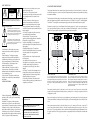
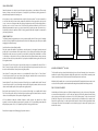
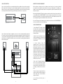
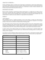
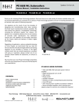
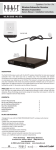
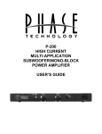
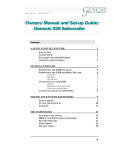
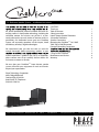
5.1 Reference Speaker System • Installation Instructions
est sound reproduction products available. We hold several key patents in loudspeaker technology, including the
soft-dome tweeter. Our mission, our passion is to constantly advance the art and science of accurate audio reproduction. Our dedication insures your new CineMicro
System will accurately reproduce all the impact, detail
and delicacy of today’s digital technologies.
We recommend that you take the time to read this
manual thoroughly before connecting speakers to your
should experience a problem with set-up or operation,
please contact one of our carefully chosen dealers for
assistance, or contact us directly.
CONTENTS:
Thank you
Table of Contents
Safety Instructions
Home Theater Speaker Placement
Subwoofer Placement
Speaker Connections
Mounting the CineMicroOne On A Wall
Table Top or Shelf Placement
Powered Subwoofer Connections
Caring for the CineMicroOne
Maintenance and Service
Warranty
1
1
2
3
4
4
5
5
6
7
7
8
8
8
We trust that your CineMicroOne home theater speaker
system will enrich your enjoyment of music and movies
beyond your expectations.
Phase Technology Corporation
8650 College Boulevard
Overland Park, KS 66210
(888) PHASE-TK Telephone
(913) 663-9790 Fax
8650 College Boulevard.
Overland Park, KS
66210
•
888-PHASE-TK
•
www.phasetech.com
•
www.mseaudio.com
SAFETY INSTRUCTIONS
CAUTION
RISK OF ELECTRIC
SHOCK
HOME THEATER SPEAKER PLACEMENT
!
CAUTION: To reduce the risk of electric shock, do not remove cover (or
back). No user-serviceable parts inside. Refer servicing to qualified service
personnel.
Explanation of Graphical Symbols
The lightning flash with arrowhead symbol, within
an equilateral triangle, is intended to alert you to the
presence of un-insulated “dangerous voltage: within the
product’s enclosure that may be off sufficient magnitude
to constitute a risk of electric shock to persons.
!
The exclamation point within an equilateral triangle
is intended to alert you to the presence of important
operating and maintenance (servicing) instructions in the
literature accompanying the appliance.
1. Read Instructions - All the safety and operating
instructions should be read before the appliance is
operated.
2. Retain Instructions - The safety and operating
instructions should be retained for future reference.
3. Heed Warnings - All warnings on the appliance and
in the operating instructions should be adhered to.
4. Follow Instructions - All operating and other
instructions should be followed.
5. Water and Moisture - The appliance should not
be used near water - for example, near a bathtub,
washbowl, kitchen sink, laundry tub, in a wet basement,
or near a swimming pool, etc.
6. Carts and Stands - The appliance should be used
only with a cart or stand that is recommended by the
manufacturer.
PORTABLE CART WARNING
from heat sources such as radiators, stoves, or other
appliances that produce heat.
10. Power Source - The appliance should be
connected to a power supply only of the type described
in the operating instructions or as marked on the
appliance.
11. Power Cord Protection - Power supply cords
should be routed so that they are not likely to be
walked on or pinched by items placed up or against
them, paying particular attention to cords at plugs,
convenience receptacles, and the point where they exit
from the appliance.
12. Cleaning - The appliance should be cleaned only
as recommended by the manufacturer.
13. Nonuse Periods - The power cord of the
appliance should be unplugged from the outlet when
left unused for a long period of time.
14. Object and Liquid Entry - Care should be taken
so that neither objects fall nor liquids spill into the inside
of the appliance.
15. Damage Requiring Service - The application
should be serviced by qualified service personnel when:
a. the power supply cord or the plug has been
damaged,
b. objects have fallen onto or liquid has been spilled
into the appliance,
c. the appliance has been exposed to rain,
d. the appliance does not appear to operate normally
or exhibits a marked change in performance, or
e. the appliance has been dropped or the cabinet
damaged.
16. Servicing - The user should not attempt to service
the appliance beyond those means described in the
operating instructions. All other servicing should be
referred to qualified service personnel.
17. Grounding or Polarization - Precautions should
be taken so that the grounding or polarization means of
an appliance is not defeated.
Today’s digital multi-channel home theater technology has elevated the art of “surround sound” to reproduce the
movie theater experience in your own home. Speaker requirements and placement are important when reproducing
these multi-media effects.
Two front speakers (left and right), two surround speakers (left and right), a center-channel speaker, and a subwoofer
define the minimum arrangement for multi-channel systems such as Dolby® Pro Logic, DTS™, and Dolby Digital.
The CineMicroOne was designed as a matched system to give you the most realistic seamless experience possible.
Placement of speakers in your room will impact the final listening experience. To position your speakers, there are
some general guidelines that take room size, shape, and fixtures and furnishings into account. Use the following
illustrations as a general guide for speaker placement in a typical home theater system.
LF
C
LF
RF
C
RF
SUB
SUB
SUB
RS
LS
LS
RS
LR
5.1 HOME THEATER SYSTEM
In a 5.1 home theater system, the center channel (C) should be
placed at 0º directly below or above the video screen, the left front
(LF) and right front (RF) speakers should be placed at 30º from the
listening area, and the left and right surrounds (LS and RS) should
be placed at 110º. All five speakers should be placed at or near ear
level.
RR
7.2 HOME THEATER SYSTEM
In a 7.2 home theater system, the center channel (C) should be
placed at 0º directly below or above the video screen, the left front
(LF) and right front (RF) speakers should be placed at 30º from the
listening area, and the left and right surrounds (LS and RS) should
be placed at 90º. The left rear (LR) and right rear (RR) speakers (sold
separately) should be placed at 150º. All seven speakers should be
placed at or near ear level.
Front speakers should be placed 6-8 feet apart (or on the sides or your screen if your screen is wider) to fully
separate the left and right channels. Whether placed on speaker stands or on shelves, your speakers should be at
or slightly above ear level.
7. Wall or Ceiling Mounting - The appliance should be
mounted to a wall or ceiling only as recommended by
the manufacturer.
8. Ventilation - The appliance should be situated so
that its location or position does not interfere with its
proper ventilation. For example, the appliance should not
be situated on a bed, sofa, rug, or similar surface that
may block the ventilation openings; or placed in a builtin installation, such as a bookcase or cabinet that may
impede the flow of air through the ventilation openings.
9. Heat - The appliance should be situated away
APPLICABLE FOR USA, CANADA OR WHERE
APPROVED FOR USAGE
CAUTION: TO PREVENT ELECTRIC SHOCK, MATCH WIDE
BLADE PLUG TO WIDE SLOT, INSERT FULLY.
ATTENTION: POUR EVITER LES CHOCS ELECTRIQUES,
INTRODUIRE LA LAME LA PLUS LARGE DE LA FICHE
DANS LA BORNE CORRESPONDANTE DE LA PRESE ET
POUSSER JUSQU AU FOND.
Rear surround speakers also should be placed at or slightly above your listening position for the best reproduction
of surround-sound effects. Ideally, they should be facing into your favorite listening position from either side of the
room.
Center speaker placement should be, if possible, directly on top of or under your TV monitor or projection TV
screen. Center speakers should be placed in a horizontal orientation, directly below (or above) the center of your
video screen. This correctly positions the critical sound track information (usually dialogue) that filmmakers direct to
the center channel. Phase Technology center speakers are magnetically shielded so that they will not interfere with
any TV’s.
3
SUBWOOFER PLACEMENT
Subwoofer placement is less critical, because the frequencies they reproduce are omni directional. This means the
human ear doesn’t perceive these low frequencies as coming from a specific direction, enabling placement of a
subwoofer virtually anywhere in the listening room.
Center Speaker
Left
Front
It’s best, however, to keep a subwoofer within the sound field of the other speakers. The closer the subwoofer is
to a wall, the louder and more intense its bass output will be: this effect is even stronger when the sub is placed in
or near a room’s corner. If using two subwoofers, start by placing them next to the front left and right speakers, in
both front corners or one in the corner and one 1/3 of the way along the front wall from the corner. Each room is
different. Experiment with these options or try other locations until you get the best results. If you must choose a
less-than-ideal position, the output level of Phase Technology powered subwoofers is adjustable to compensate for
your listening environment.
Right
Front
SUB OUT
Left Right
Front Front
Subwoofer
Left Right
Surr. Surr.
Center
Channel
Amplifier Panel
Line Input
SPEAKER CONNECTIONS
The following instructions apply whether you are using a separate amplifier or Home Theater receiver. For simplicity
we will use the term “amplifier” throughout this manual to mean both. With system power off and your amplifier
unplugged, please follow these steps:
Special Note: Observe Speaker Polarity Carefully!
Every cable, speaker and amplifier is clearly marked to show their positive (+) and negative (-) terminals. Amps and
speakers may use some combination of these symbols and/or colors to indicate positive (usually red) and negative
(usually black or white) connections. One strand of your cable will also be ridged and/or marked with a colored line
or other indicator on the positive side. For proper polarity and, thus, ideal system performance, always connect the
positive side of the cable to the positive terminals on your speakers and amplifier and the negative side of the cable
to the negative terminals.
Front Speakers: The pair of front speaker connections (left and right) on your amplifier will be labeled “Front” or
“Main.” Connect the speaker cables for your left and right front speakers using these terminals and then connect
the cables to the front satellites. Observe positive and negative polarities.
Center Speaker: The center speaker connections on your amplifier will be labeled “Center” or “Center Channel.”
Connect the speaker cables for your center channel speaker using these terminals and then connect the cables to
the center speaker. Observe positive and negative polarities.
Surround Speakers: The pair of surround connections (left and right) on your amplifier will be labeled “Surround.”
Connect the speaker cables for your left and right surround speakers using these terminals and then connect the
cables to surround satellite speakers. Observe positive and negative polarities.
Rear Speakers (optional purchase): The pair of rear connections (left and right) on your amplifier will be labeled
“Rear.” Connect the speaker cables for your left and right rear speakers using these terminals and then connect the
cables to the rear satellite speakers. Observe positive and negative polarities.
6.1-7.2 and Additional Subwoofers: Individual CineMicroOne satellite speakers and subwoofers are offered
separately. One or two extra satellites can expand your 5.1 system into a 6.1 or 7.1 system. Adding an extra subwoofer
will expand your system to a 5.2, 6.2, or 7.2 system. Ask your Phase Technology dealer for details.
Right
Surround
Left
Surround
MOUNTING THE CINEMICROONE ON A WALL
The four satellites and center channel include keyhole-style inserts for on-wall mounting. Use an 8 mm screw in a
drywall anchor capable of holding 2-3 times the weight of the speaker in the location you wish to mount the speaker.
Leave the screw head about 1/4” out of the anchor, then slide the keyhole insert over the screw.
Additionally, the four satellite and one center channel speakers feature M5 (5 mm) threaded inserts mounted on the
rear or bottom of the speakers for use with standard wall mounting brackets (available from third party vendors).
TABLE TOP OR SHELF PLACEMENT
Included with your CineMicro speakers are self adhesive bumpers that can be used on the bottoms of the speakers
to protect the finish when placing it on a shelf or table top. Simply peel off four of the bumpers from the backing
paper and apply the four bumpers to the bottoms of each of the satellite speakers. To keep the center channel
speaker from rocking and to level the speaker, two angled plastic feet are included that can be attached to the
bottom of the speaker cabinet. Use to two supplied screws to attach the feet to the left and right threaded inserts
in the bottom of the cabinet. Two extra bumpers are also included to apply to the bottom of the speaker to protect
the finish of the cabinet.
Please refer to the diagram on the following page for speaker connections.
4
5
SUBWOOFER CONNECTIONS
AMPLIFIER SETUP AND BASS MANAGEMENT
Option 1: Low Level Setup This is the recommended method for those amplifiers and receivers that are equipped
with a “Subwoofer Out” or “Pre-Amp Out” connection. Virtually all audio/video receivers have this connection clearly
marked on the rear panel. Run a dedicated interconnect cable with RCA connectors from the subwoofer output jack
to the line input on the subwoofer. In this setup, you will be using the internal crossover on your processor.
Many home theater receivers/processors have a feature that controls how the bass is processed and delivered
to the subwoofer. It also adjusts the amount of bass that is sent to your satellite speakers. Look carefully in your
amplifier or receiver’s instruction manual for details on how to adjust for the speaker size (sometimes called “Speaker
Setup”) for your system.
When using a Dolby Digital or DTS-capable receiver/processor with the subwoofer connected to the subwoofer out
on your amplifier turn the “LOW-PASS FREQUENCY” control to the highest setting (200 Hz) on the back of your
subwoofer. Set the subwoofer crossover setting in the speaker setup section of the amplifier setup menu to 150 HZ
(or the next highest setting) and set the Satellites and Center channels to “small”.
Subwoofer
SUB OUT
Left Right
Front Front
Center
Channel
Left Right
Surr. Surr.
Line Input
If you are NOT using the receiver’s internal processor for subwoofer control then turn the “CROSSOVER FREQUENCY”
control on the subwoofer to the 3 o’clock (150 Hz) setting.
Amplifier Panel
SUBWOOFER AMPLIFIER PANEL
Option 2: High Level Input Setup If your amplifier or receiver does not have a dedicated subwoofer output, it will
be necessary to connect your new subwoofer directly to the speaker output terminals on the back of the unit. In this
scenario, you will be running high quality speaker wires from the left and right front outputs of your amplifier to the
high level inputs on the subwoofer. You will then need a second set of wires to carry the signal from the subwoofer
back to the main speakers.
Left
Front
Center Speaker
Right
Front
Amplifier Panel
SUB OUT
Left Right
Front Front
Center
Channel
Left Right
Surr. Surr.
Subwoofer
To Speaker
Right
Left
From Receiver
Right Input
Left Input
2
1. Power ON/Auto/OFF: This switch, when left
in the “Auto” position, automatically activates the
subwoofer when an audio signal is detected and
shuts the subwoofer off after approximately ten
(10) minutes of silence.
4
6
1
5
2. Subwoofer Level Control: Adjusts the volume
of bass energy allowing you to customize overall
tonal balance to your individual room acoustics
and personal taste.
3.
Crossover
Frequency
Control:
This
adjustment varies the point at which the
subwoofer takes over the task of creating low
bass frequencies from the rest of the audio
signal permitting additional fine tuning of the total
system. A little experimentation with this control
will allow you to match the performance of the
subwoofer to the rest of your speakers resulting
in extraordinary, accurate, deep bass response.
This control should be turned to its highest
setting when the sub is connected through the
Subwoofer out on your receiver.
4. Phase Control: This adjustment matches the
phase - the in and out movement of speaker
cones - to that of your main speakers. Adjust this
control by listening to music with bass content.
The setting is correct when the bass sounds the
fullest.
5. High Level Input and Output: Used for direct
speaker connections from the left and right front
speaker outputs when a low-level subwoofer
output is not available.
6. Low Level Input: Used from pre-out or
Subwoofer-out.
6
3
7
CARING FOR THE CINEMICROONE
All Phase Technology speakers are finished with a high degree of craftsmanship in either hand polished paint or
vinyl laminates. We recommend using a lint-free rag with a small amount of glass cleaner to maintain the long-lasting
beauty of the finish. Avoid products containing silicones, oils, oil derivatives, or solvents. Enclosures finished in vinyl
laminates may be cleaned with a damp cloth as necessary.
MAINTAINENCE AND SERVICE
Because of Phase Technology’s uncompromising quality control programs, it’s unlikely that your speakers will ever
need service if connected and used as outlined in this Owners’ Manual. In the unlikely event that a problem does
occur, please contact your Phase Technology dealer. Your dealer has the necessary factory-authorized parts and
trained technicians to quickly restore your speaker to its original performance specifications.
WARRANTY
LIMITED WARRANTY
Phase Technology warrants its CineMicro loudspeakers to be free from defects in material and workmanship for
a period of ten (10) years for speaker product and three (3) years for the electronic components to the original
purchaser. Purchase must be made from an authorized Phase Technology dealer.
This warranty does not cover service or parts to repair damage caused by misuse, abuse, damage while in transit,
alterations, unauthorized repairs, failure to follow instructions, fire, flood or any other cause beyond the reasonable
control of Phase Technology. Defects in speaker cabinets or grilles must be brought to the attention of your dealer
immediately after purchase. This warranty will be void if the products’ serial number has been altered or removed.
To obtain warranty service, defective product must be shipped in its original carton or equivalent together with
original invoice or bill of sale, insured and prepaid to your authorized Phase Technology dealer or the factory when
warranty service is requested.
If you choose to return the defective product to the factory you must first call us at (888) phase-tk to obtain a Return
Authorization number prior to shipping. Product repaired under this warranty will be returned to you freight collect.
SPECIFICATIONS
Impedance
8 ohms
Sensitivity
87 dB
Frequency Response
35 Hz - 20 kHz
Tweeter
3/4” dome
Woofer
3” cone
Recommended Amp Power
100 watts per channel
Dimensions
Satellite
Center
Subwoofer
4 3/8” w x 6 1/2” h x 4 7/8” d
10 1/4” w x 4 3/8” h x 4 7/8” d
10 3/4” w x 14 3/4” h x 15 1/8” d
8