1
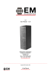
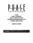
SPF Outdoor Speaker Series
T E
C H
N O L O G Y
Owners Manual / Installation Instructions
Power FL-8 Power FL-10 Power FL-12
Solaris
ATS-1- - All Terrain Speakers
Thank you for selecting Phase Technology speakers. We know there are a wide variety of choices available today, and
we sincerely appreciate your purchase of our product. Phase Technology speakers are built to exacting standards and
will provide many years of listening enjoyment.
Our speakers are the result of over five decades of
designing and manufacturing what many consider
the finest sound reproduction products available. We
hold several key patents in loudspeaker technology
including the soft-dome tweeter. Our mission, our
passion is to constantly advance the art and science
of accurate audio reproduction. Our dedication
insures your new speakers will accurately reproduce
all the impact, detail and delicacy of today’s digital
technology.
Regardless of application, serious audiophile
listening or home theater, we recommend that you
take the time to read this manual thoroughly before
connecting speakers to your amplifier or receiver. In
the highly unlikely event that you should experience
a problem with set-up or operation, please contact
one of our carefully chosen dealers for assistance, or
contact us directly.
We trust that your new Phase Technology speakers
will enrich your enjoyment of music and movies
beyond your expectations.
ATS-1
CONTENTS:
ATS-1 FEATURES:
ATS-1 FEATURES
SAFETY PRECAUTIONS
PLACEMENT
AMPLIFIER CONNECTIONS
SUBWOOFER CONNECTIONS
ADJUSTING THE ATS-1
WALL MOUNTING
RUBBER FEET
CARING FOR YOUR SPEAKERS
SERVICE ISSUES AND WARRANTY
SPECIFICATIONS
Phase Technology Corporation
1
2
3
3
4
5
5
6
6
6
6
6400 Youngerman Circle
1” soft dome tweeters
80 watts of continuous power
Strength to withstand UV rays, weed whackers, moisture
Theft control hardware
Adjustable C clamps and inserts for OmniMountTM brackets
Jacksonville, Florida 32244
1.888.PHASE TK
www.phasetech.com
SAFETY INSTRUCTIONS
CAUTION
RISK OF ELECTRIC SHOCK
DO NOT OPEN
9. Heat - The appliance should be situated away
from heat sources such as radiators, stoves, or other
appliances that produce heat.
10. Power Source - The appliance should be connected
to a power supply only of the type described in the
operating instructions or as marked on the appliance.
11. Power Cord Protection - Power supply cords should
be routed so that they are not likely to be walked on
or pinched by items placed up or against them, paying
particular attention to cords at plugs, convenience
receptacles, and the point where they exit from the
appliance.
12. Cleaning - The appliance should be cleaned only as
recommended by the manufacturer.
13. Nonuse Periods - The power cord of the appliance
should be unplugged from the outlet when left unused
for a long period of time.
14. Object and Liquid Entry - Care should be taken so
that neither objects fall nor liquids spill into the inside of
the appliance.
15. Damage Requiring Service - The application should
be serviced by qualified service personnel when:
a. the power supply cord or the plug has been damaged,
b. Objects have fallen onto or liquid has been spilled into
the appliance,
c. the appliance has been exposed to rain,
d. the appliance does not appear to operate normally or
exhibits a marked change in performance, or
e. the appliance has been dropped or the cabinet
damaged.
16. Servicing - The user should not attempt to service
the appliance beyond those means described in the
operating instructions. All other servicing should be
referred to qualified service personnel.
17. Grounding or Polarization - Precautions should be
taken so that the grounding or polarization means of an
appliance is not defeated.
!
CAUTION: To reduce the risk of electric shock, do not remove cover (or
back). No user-serviceable parts inside. Refer servicing to qualified service
personnel.
Explanation of Graphical Symbols
The lightning flash with arrowhead symbol, within an
equilateral triangle, is intended to alert you to the
presence of un-insulated “dangerous voltage: within the
product’s enclosure that may be off sufficient magnitude
to constitute a risk of electric shock to persons.
!
The exclamation point within an equilateral triangle
is intended to alert you to the presence of important
operating and maintenance (servicing) instructions in the
literature accompanying the appliance.
1. Read Instructions - All the safety and operating
instructions should be read before the appliance is
operated.
2. Retain Instructions - The safety and operating
instructions should be retained for future reference.
3. Heed Warnings - All warnings on the appliance and in
the operating instructions should be adhered to.
4. Follow Instructions - All operating and other
instructions should be followed.
5. Water and Moisture - The appliance should not be
used near water - for example, near a bathtub, washbowl,
kitchen sink, laundry tub, in a wet basement, or near a
swimming pool, etc.
6. Carts and Stands - The appliance should be used
only with a cart or stand that is recommended by the
manufacturer.
PORTABLE CART WARNING
7. Wall or Ceiling Mounting - The appliance should be
mounted to a wall or ceiling only as recommended by the
manufacturer.
8. Ventilation - The appliance should be situated so that
its location or position does not interfere with its proper
ventilation. For example, the appliance should not be
situated on a bed, sofa, rug, or similar surface that may
block the ventilation openings; or placed in a built-in
installation, such as a bookcase or cabinet that may
impeded the flow of air through the ventilation openings.
APPLICABLE FOR USA, CANADA OR WHERE APPROVED FOR
USAGE
CAUTION: TO PREVENT ELECTRIC SHOCK, MATCH WIDE BLADE
PLUG TO WIDE SLOT, INSERT FULLY.
ATTENTION: POUR EVITER LES CHOCS ELECTRIQUES,
INTRODUIRE LA LAME LA PLUS LARGE DE LA FICHE DANS LA
BORNE CORRESPONDANTE DE LA PRESE ET POUSSER JUSQU
AU FOND.
2
PLACEMENT
The ATS-1 “All Terrain Speaker” is designed for indoor and outdoor playback of music and home theater sources.
Each speaker includes a convenient stand / mount with a ball and socket type swivel adjustment to facilitate aiming
the speaker at your seating area. As you unpack your speaker, please note the allen (hex) wrench provided that will
be required to set the correct speaker angle. The ATS-1 is video shielded for safe placement on or near a television
or computer monitor.
AMPLIFIER CONNECTIONS
Before making any connection, make sure your stereo amplifier or receiver’s power is turned off. Each speaker has
a red (+) terminal and a black (-) ground terminal which will match the speaker output terminals on your amplifier or
receiver. Correctly connecting red to red and black to black from your amplifier to your speaker will ensure correct
phase connection. We recommend 16-guage or heavier wire for the best performance for your speakers. Choose
speaker wire that defines each conductor with color coding or texture on at least one of the two wire leads to ensure
proper phase connection. If our home theater receiver has a set-up menu, we recommend that the “small” setting
be selected for the front left and right, center and surround speakers.
The diagram below illustrates a typical home theater hook up:
CENTER
RIGHT FRONT
LEFT FRONT
AMPLIFIER
FRONT
REAR
LEFT REAR
CENTER
RIGHT REAR
3
SUBWOOFER CONNECTIONS
You may choose to use a subwoofer with your ATS-1 to enhance the bass response of your music system. The
Phase Technology Power 8 is well-suited for the use with the ATS-1. There are two ways to connect the ATS-1 in a
home theater system with a powered subwoofer. The LOW-LEVEL diagram below may be utilized with receivers or
processors that feature subwoofer or low frequency outputs. This type of output utilizes RCA connectors.
Note: Most processors and receivers have a single (mono) sub-out. Connect the subwoofer output from your
receiver/processor to either the left input or the right input on your subwoofer amplifier.
The HIGH-LEVEL (speaker level) diagram below illustrates the typical subwoofer wiring utilizing the speaker output
terminals of the amplifier or receiver. This hook-up method illustrates the ATS-1 connection to the subwoofer.
LOW-LEVEL SUBWOOFER HOOKUP
HIGH-LEVEL SUBWOOFER HOOK-UP
AMPLIFIER MAIN SPEAKER OUTPUTS
RECEIVER/PROCESSOR
L
L
R
LINE
OUT
LA
R
RA
LINE
IN
LINE
OUT
LINE
IN
L
L
LEFT SPEAKER
RIGHT SPEAKER
R
R
SUBWOOFER
AMPLIFIER
SUBWOOFER
AMPLIFIER
L
L
R
R
INPUT
INPUT
OUTPUT
OUTPUT
4
ADJUSTING THE ATS-1
The ATAS-1 comes with a convenient stand/mount . A ball at the top of the post fits into a socket molded into the
back of the speaker. A retaining collar holds the ball in place in the socket providing adjustment of the angle of the
speaker, permitting the speaker to be aimed at the ideal listening area. The retaining collar has three allen (hex) type
screws to secure the speaker angle. An allen wrench is provided with each speaker to loosen and tighten the screws.
Note: Always loosen the screws on the retaining collar before you attempt to change the angle of your speaker on the
bass. Failure to do so may result in damage to the post.
The screws in the retaining collar may be loosened by inserting the allen wrench into the screw head and turning the
screws in a counter-clockwise direction. Once you have determined the desired angle, tighten the retaining screws by
turning them in the clockwise direction until snug. Avoid over-tightening the retaining screws.
WALL MOUNTING
The base assembly is pre-drilled for fastening to a shelf, wall or ceiling. Before mounting the ATS-1 to a wall or
ceiling, it is important to consider the surface material on which the speaker will be mounted. If you intend to mount
the speaker to wood, traditional 1” long wood screws will secure the speaker properly. Mounting to stucco, plaster or
drywall will require additional measures to properly secure the speaker to one of these surfaces. Consult your Phase
Technology dealer for assistance.
You will find it much easier to mount the base if you first remove the speaker from the mounting post. To remove
the speaker from the post, first place the speaker face down on a soft surface such as carpet or a hand towel. The
speaker is secured to the mounting post by three allen head screws located in the retaining collar. Using the allen
wrench supplied with the ATS-1, remove the three screws. You now have clear access to the mounting holes in the
base. With the speaker removed from the base, use the base as a template to locate the desired speaker placement.
Hold the base at the location at which the speaker is to be mounted, then mark the mounting holes with a pencil.
Secure the base to the mounting surfaces with the appropriate screws.
5
Note: For ceiling or wall mounting, it is recommended to center the base on a stud or wood frame member within
your structure whenever possible. Once the base is properly secured, the speaker may be replaced on the mounting
post.
Before you replace the speaker on the mounting post, connect the speaker wire to the terminals on the back of
the speaker. Once you have connected the wire, place the speaker on the mounting post and replace the retaining
collar and screws using the allen wrench. Hold the speaker at the desired angle and tighten the screws. Avoid overtightening the screws. Always loosen the retaining screws before attempting to change the speaker angle.
RUBBER FEET
Peel-and-stick rubber feet are provided for the bottom of the base. It is recommended that the feet be applied to the
base when using the ATS-1 on a shelf of other flat surface to prevent marring the surface and to prevent the ATS-1
from sliding due to vibration.
CARING FOR YOUR SPEAKERS - OUTDOOR USE
Your ATS-1 speakers are engineered for both indoor and outdoor use and operation. Random water hitting the
speaker will not damage your ATS-1, making it ideally suited for placement in close proximity to swimming pools and
spas. The ATS-1 is not intended for use underwater, however.
Ordinary dust and dirt accumulation will not harm the ATS-1. If you wish to clean the ATS-1, household glass cleaning
solution sprayed on a paper towel may be used for light cleanup. For heavier stains, a soap and water solution
applied with a rag or sponge should remove the dirt and stains. Avoid spraying the ATS-1 with a high-pressure hose.
SERVICE ISSUES AND WARRANTY
Phase Technology has an uncompromising commitment to quality assurance. In the unlikely event that a problem
occurs with your ATS-1, please contact your Phase Technology dealer. Your new ATS-1 comes with a warranty to
protect you, the original purchaser, for a period of ten years again defects in material and workmanship. Please refer
to the warranty card included with this manual.
SPECIFICATIONS
Tweeter
Woofer
1” soft dome
4” mineral filled cone with butyle rubber surround
Shielding
Video shielded
Crossover
12 dB per octave @ 2.5 kHz
Frequency
80 Hz - 20 kHz
+ 3 dB
Amp Power
80 Watts continuous
Sensitivity
90 dB
Impedence
Dimensions*
Finish
6 Ohms
6 7/8” H x 8 1/8” W x 6 3/8” D
Black or white
* All measurements include the base /mount assembly.
Phase Technology Corporation
6400 Youngerman Circle
Jacksonville, Florida 32244
6
1.888.PHASE TK
www.phasetech.com