1
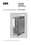
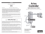
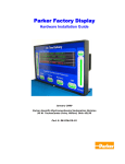
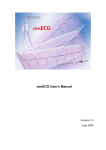
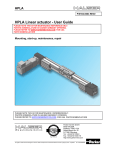
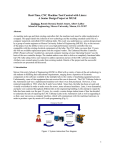
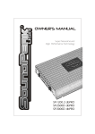
PL1100 Power Supply
User Guide
Part No: 1600.323.02 May, 2003
PL1100 POWER SUPPLY
PL1100 Power Supply
General Description
The PL1100 is a linear power supply with a rated output of 1120W (80V/14A) for use with
ViX and XL series drives. The supply requires a suitably rated transformer supplying 50V
AC RMS for the HV and 20V AC RMS for the +24V DC. The use of the PL1100 offers the
following benefits:
•
•
•
•
Provides 80V HV and +24V DC output
Single or three phase operation
Built-in power dump switch
Integral fusing
Physical Appearance
The supply is contained within an aluminium case as shown in Figure A-1. Mounting holes
allow it to be attached to a panel using four 4mm screws. Alternatively, a DIN rail mounting
option can be ordered.
Figure A-1. PL1100 Power Supply
Accessories
The following accessories may be ordered with the PL1100:
•
•
•
TO255 1000VA HV transformer
TO256 120VA Logic supply transformer
DIN rail mounting kits, two required
1600.323.02 May 2003
1
2
PL1100 POWER SUPPLY
Dimensions
The overall dimensions of the supply are 143mm deep, 119mm wide and 145mm high.
Refer to Figure A-2 for details.
116.6
142.8
1.8
143
134.3
124.3
32.03
4.
5
108.1
56.1
+24V
HV
CAUTION
Risk of electric shock.
High voltage remains on terminals
after power is removed.
Allow 5 minutes for capacitors
to discharge.
REGEN
X1
MOTOR HV OUT
0V
20V AC IN
PL1100
145
PE
+24V DC OUT
135
125
81.12
MOTOR 0V.
EXT. BRAKING RES.
20V AC IN
Power Supply
55V
AC IN
1/3 PH.
LINK
FOR
SINGLE
PHASE
L3
L2
L1
X2
All dimensions in mm
4.5
Figure A-2. Supply Dimensions
Mounting Information
Mount the supply vertically, near the drives it will supply. Both the top 4.5mm diameter fixing
holes and the bottom two 4.5mm width fixing slots should be used.
Mount the supply with a minimum free space of 50mm both below and above its case. Allow
a side clearance of 10mm free space on both sides.
Note, do not mount the supply above or close to other products which generate a significant
amount of heat by radiation or convection.
PL1100 POWER SUPPLY
3
Front Panel Layout
Figure A3 shows the location of connectors X1 and X2 and the three LEDs.
+24V
HV
CAUTION
Risk of electric shock.
High voltage remains on terminals
after power is removed.
Allow 5 minutes for capacitors
to discharge.
REGEN
X1
MOTOR HV OUT
MOTOR 0V.
EXT. BRAKING RES.
X1
PE
+24V DC OUT
0V
20V AC IN
PL1100
20V AC IN
Power Supply
55V
AC IN
1/3 PH.
LINK
FOR
SINGLE
PHASE
L3
L2
X2
L1
X2
Figure A-3. PL1100 Front Panel
AC Input Connections
Make all AC input connections to X2, the lower eight-way screw connections.
The supply requires two AC input connections, a high current 50V AC RMS for the main HV
output and a 20V AC RMS supply for the 24V DC logic supply. The main high current supply
input connections allow the use of a single phase or three-phase transformer. If you are
using a three-phase derived supply the secondary voltage required will depend upon the
type of connection used, star or delta.
All the high current AC input connections share two connector positions giving two
connection points for L1, L2 and L3. For a single-phase AC input, link L2 to L3.
Note: The front panel input voltage markings are no-load values, but the recommended
transformer is specified at its full-load value. This accounts for the 18V secondary used to
supply the 20V input and the 50V secondary used to supply the 55V input.
4
PL1100 POWER SUPPLY
Main High Current Input
Single Phase Supply
Wire the secondary of the single-phase transformer to connection points L1 and L2 as
shown in Figure A-4. Use approved cable, with a minimum wire size of 2.5mm2.
TRANSFORMER
SECONDARY
WINDING
50V AC
Link for
single phase
L3
L2
L1
Figure A-4. Single-Phase AC Secondary Connection
PL1100 POWER SUPPLY
Secondary Voltage
An AC secondary voltage of 50V RMS limits the upper AC voltage to a value below 61V
max. Using a 230V AC RMS supply for the primary and assuming a transformer regulation
of 5%, the maximum secondary AC voltage is given by:
50V +15%(AC supply upper tolerance) = 57.5V + 3.5%(transformer regulation) = 59.5V
which is below the supplies maximum input limit of 61V.
Dual Secondary Windings
When using a dual secondary wired in parallel, use the connections shown in Figure A-5.
This connection method takes advantage of the shared connection points available on X2.
This is the connection method used with the TO255 1000VA transformer, shown in
Figure A-5.
TRANSFORMER
SECONDARY
WINDINGS
Red
Brown
Brown
115V
Violet
115V
AC
Grey
115V
Blue
230V
AC
115V
50V AC
Violet
0V
Black
Grey
115V
Blue
L3
50V AC
0V
Yellow
L2
Orange
L1
Figure A-5. Single-Phase AC Dual Secondary Connection
HV Transformer Specification (TO255)
Power rating
Input voltage
Output voltage
Output current
Regulation
Size
Weight
Mounting
1000VA
230V +15% -10%
2 X 50V RMS full load voltage
2 X 10A RMS
3.5%
162mm diameter, 70mm height
6.5Kg
resin filled centre, drilled to accept an 8mm mounting screw
Note:
A Neoprene insulating disc is included with the mounting kit to prevent the crushing of
transformer windings. This disc provides a 5kV isolation barrier between the transformer
and mounting panel.
5
6
PL1100 POWER SUPPLY
Three Phase Supply
Depending upon the connection method used, star or delta, wire the three-phase secondary
as shown in Figures A-6 and A-7. Use approved cable, with a minimum wire size of 2.5mm2.
TRANSFORMER
SECONDARY
WINDINGS
30V
30V
30V
L3
L2
L1
Figure A-6. Three-Phase Star Secondary Connection
Note: Make the star connection at the transformer.
PL1100 POWER SUPPLY
TRANSFORMER
SECONDARY
WINDINGS
50V AC
50V AC
50V AC
L3
L2
L1
Figure A-7. Three-Phase Delta Secondary Connection
Input Supply Fuses
AC inputs L1, L2 and L3 are each internally fuse protected by circuit board mounted 32A
time lag fuses in positions AC1, AC2 and AC3.
The fuse types are 32A TL HB 6.3 X 32mm.
7
8
PL1100 POWER SUPPLY
Logic Supply Input
The logic supply AC input will require a single-phase 18V AC RMS input capable of
supplying 6A. The supply is connected between the two ‘20V AC IN’ connection terminals of
X2. Alternatively, if a 24V DC supply is already present, route it directly to the drives.
Logic Supply Fuse
A 10A time lag fuse protects the AC input supply to the logic supply bridge rectifier. The fuse
used is a 10A TL HB 5 X 20mm.
Suitable Transformer (TO256)
A +24V DC logic supply can use the TO256 120VA toroidal transformer (see Figure A-8),
which has the following specification:
Power rating
Input voltage
Output voltage
Output current
Regulation
Size
Weight
Mounting
120VA
230V +15% -10%
2 X 18V RMS full load voltage
2 X 3.3A RMS
5.5%
93mm diameter, 46mm height
1.2Kg
resin filled centre, drilled to accept an 8mm mounting screw
Note:
A Neoprene insulating disc is included with the mounting kit to prevent the crushing of
transformer windings. This disc provides a 5kV isolation barrier between the transformer and
mounting panel.
TRANSFORMER
SECONDARY
WINDINGS
Brown
Brown
115V
Violet
115V
AC
Grey
115V
Blue
230V
AC
Red
115V
18V AC
Violet
0V Black
Grey
Yellow
115V
18V AC
Blue
L3
0V Orange
Figure A-8. PL1100 X1 Connections
L2
L1
PL1100 POWER SUPPLY
9
DC Output Connections
Make all DC output connections to X1, the upper eight-way screw connections. Figure A-9
shows the detail of the PL1100‘s front panel, indicating the connection information for
connector X1.
+24V
HV
REGEN
X1
MOTOR HV OUT
MOTOR 0V.
EXT. BRAKING RES.
PE
+24V DC OUT
0V
Figure A-9. PL1100 X1 Connections
The MOTOR HV OUT is the main HV positive output, shared between the top two screw
terminal connectors. The return connections also share two screw terminal connectors
marked as MOTOR 0V. Connect any brake or dump resistor between HV and the EXT.
BREAKING RES. connection. Each terminal will accept a maximum wire size of 2.5mm2.
Figure A-10 shows the PL1100 output wiring for two ViX drives. This illustrates how to route
the main HV supply separately to each drive. The lower current requirements of the +24V
logic/brake supply can allow the wiring to be linked between drives.
10
PL1100 POWER SUPPLY
+24V
HV
CAUTION
Risk of electric shock.
High voltage remains on terminals
after power is removed.
Allow 5 minutes for capacitors
to discharge.
REGEN
HV ST FB
HV ST FB
X1
X1
10
X3
10
X3
X1
MOTOR HV OUT
MOTOR 0V.
EXT. BRAKING RES.
PE
X4
X4
+24V DC OUT
0V
1
1
X2
X2
20V AC IN
PL1100
20V AC IN
Power Supply
55V
AC IN
1/3 PH.
LINK
FOR
SINGLE
PHASE
L3
L2
X5
X5
L1
X2
10 mm MIN
Figure A-10. PL1100 Output Connections for two ViX drives
EMC Installation Guidelines
These EMC installation recommendations are based on the expertise acquired during the
development of compliant applications, which Parker believes are typical of the way, a
PL1100 may be used. Provided you have no special installation requirements or untypical
operating environment requirements, PL1100 power supplies will conform to current EMC
Directives.
If you are using the recommended transformers (TO255 & TO256) both primaries can be fed
from a single EMC filter. Use a CORCOM 12FC10 or its equivalent
Mount the supply on a conductive panel to which the EMC filter and the drive(s) are also
attached. If the panel has a paint finish, it will be necessary to remove the paint in certain
areas to ensure the filter and supply, make a good large-area metal to metal contact with the
panel.
Position the PL1100 as close as possible to the drives it is to supply (less than one metre).
Ideally, the EMC filter needs to be close to the transformers, which in turn, should be as
close to the PL1100 as can be arranged. Assuming the use of an equipment cabinet, locate
the EMC filter and transformers in the base of the cabinet and route AC supply cables up to
the PL1100. Attempt to layout the wiring in a way that minimises cross coupling between
filtered and non-filtered conductors. This means avoiding running wires from the output of a
filter close to those connected to its input. Where you wish to minimise the cross coupling
between wires avoid running them side-by-side one another, if they must cross, cross them
at 90° to each other. Keep wiring supported and close to cabinet metalwork.
PL1100 POWER SUPPLY
11
Power Dump/Braking Resistor Considerations
The power supply incorporates a regenerative power dumping circuit used to divert
regenerated power into a dump or brake resistor. The need for such a circuit should ideally
be determined during system design.
External Braking Resistor
If required by the application, fit an external braking resistor where shown to connector X1.
The need for a braking resistor should be considered if the application requires large inertial
loads to be decelerated quickly. During deceleration if the drive faults-out with over voltage
or the braking resistor (middle LED) flashes orange - requesting power dumping, it is likely a
brake resistor is required.
The internal dump switch has a peak rating of 1450W. The dump resistor used should be
5 Ohms (nominal) with a power rating of 100W. This circuit’s output is protected by a 5A
time lag fuse, used to limit power dissipation and to provide protection in the event of a dump
resistor short-circuit. The dump fuse is a 5A TL LB 5 X 20mm.
The circuit used is a relative dump switch set to operate at nominal HV + 5V. This form of
power dump circuit has the advantage of acting as a discharge path for the main supply
smoothing capacitors at power-down.
Parker offers the “PL1100-DUMP”. If any other form of resistor is used, take care to insulate
all connections and to guard against it being touched when hot. Any alternative resistor
should be wired using 16/02 0.5 mm2 cable.
To protect the dump resistor from external wiring faults we recommend that a protection fuse
is included between the HV connection and the dump resistor. A suitable value is 5A TL LB.
12
PL1100 POWER SUPPLY
LED Indicators Function
Three tri-state LEDs are positioned on the front panel of the PL1100. Their function is
described in Table A-1.
Position
Left
Colour
Green
Function
Middle
Green
Orange
HV power dump ready
HV power dump switch closed (dump
active)
Right
Green
24V present
HV present
Table A-1. LED Indicators Function
Electrical Specification
Parameter
Input voltage
Nominal
Absolute maximum
Mains supply frequency range
Output voltage
On board capacitance
Logic supply input voltage
Mains supply frequency range
+24V Logic Output
No 24V load output
3A load output
On board capacitance
Output cable length restriction
Value
55V AC RMS (under no-load
conditions)
61V AC RMS
50/60Hz +/- 2Hz
80V DC ±5% (no load)
2 x 10,000µF/100V
20V RMS (under no-load conditions)
50/60Hz +/- 2Hz
26.6V DC +/-5%
23.3V DC +/-5%
10,000µF/35V
not to exceed 10m in length
PL1100 POWER SUPPLY
13
Mechanical Specification
Parameter
Housing
Dimensions
Depth
Width
Height
Value
Aluminium case
143 mm Max
117 mm Max
145 mm Max (excludes DIN rail
mounting kit)
1.25 kg
Weight
Environment Specification
Parameter
Pollution
Installation category
Operating temperature range
Storage temperature range
Humidity
Altitude
Ingress protection
Cooling
Value
Degree 2
II* at transformer primary input
0 to 50°C ambient
-20° to 70°C
5 to 95% non condensing within
enclosure
2000 metres
IP20
Natural convection. Operation at
temperatures between 40° to 50°C will
require an airflow through the module
of 0.5m/s.
*Note: Installation category (also called Overvoltage Category) specifies the level of mains
voltage surges that the equipment will be subjected to. The category depends upon the
location of the equipment, and on any external surge protection provided.
14
PL1100 POWER SUPPLY
Contact Addresses
For engineering
assistance in Europe:
Parker Hannifin plc
Electromechanical
Automation
21 Balena Close
Poole, Dorset
England, BH17 7DX
Tel: +44 (0)1202-699000
Fax: +44 (0)1202-695750
e-mail: [email protected]
e-mail: [email protected]
Website: www.parker-eme.com
For engineering
assistance in Germany
Parker Hannifin GmbH
Electromechanical
Automation
P. O. Box: 77607-1720
Robert-Bosch-Str. 22
D-77656 Offenburg, Germany
Tel: +49 (0)781 509-0
Fax: +49 (0)781 509-176
e-mail: [email protected]
e-mail: [email protected]
Website: www.parker-eme.com
For engineering
assistance in Italy
Parker Hannifin SpA
Electromechanical Automation
20092 Cinisello Balsamo
Milan,
Italy Via Gounod, 1
For engineering
assistance in the U.S.:
Parker Hannifin Corporation
Electromechanical Automation
5500 Business Park Drive, Suite D
Rohnert Park
CA 94928
USA
Tel: (800) 358-9070
Fax: (707) 584-3793
FaxBack System: (800) 936-6939
e-mail: [email protected]
Website: www.parkermotion.com
Tel: +39 02 6601 2478
Fax: +39 02 6601 2808
e-mail: [email protected]
Website: www.parker-eme.com