1
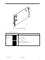
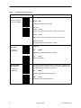
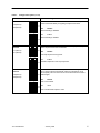
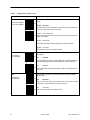
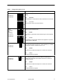
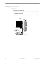
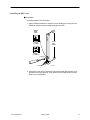
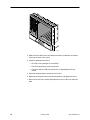
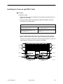
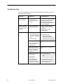
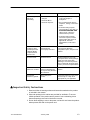
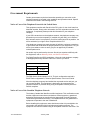
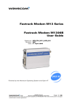
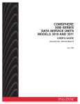
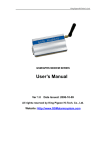
TM Model 7511 Dual DSU Startup Instructions Document Number 7511-A2-GN10-10 January 1999 Product Documentation on the World Wide Web We provide complete product documentation online. This lets you search the documentation for specific topics and print only what you need, reducing the waste of surplus printing. It also helps us maintain competitive prices for our products. Complete documentation for this product is available at www.paradyne.com. Select Service & Support → Technical Manuals → Subrate Digital Access Devices. Select the following document: 7511-A2-GB20 Model 7511 Dual DSU User’s Guide To request a paper copy of a Paradyne document: Within the U.S.A., call 1-800-PARADYNE (1-800-727-2396) Outside the U.S.A., call 1-727-530-8623 Preparation Make sure you have: A clean, well-lit, and ventilated site that is free from environmental extremes. One to two feet of clearance for cable connections. An operable network connection. Package Checklist Verify that your package contains the following: A Model 7511 DSU A backplate bearing two 25-pin connectors Two V.35 adapter cables 7511-A2-GN10-10 January 1999 1 Cables You May Need to Order You will need cables to connect your Network Interface Module (NIM) to the network and your 7511 DSUs to DTEs. For further information refer to the documentation shipped with your NIM, and Appendix A, Cables and Pin Assignments, in the User’s Guide. Installing the Dual DSU Before you install your DSU, read the Important Safety Instructions beginning on page 13. ! HANDLING PRECAUTIONS FOR STATIC-SENSITIVE DEVICES The Model 7511 Dual DSU is designed to protect sensitive components from damage due to electrostatic discharge (ESD) during normal operation. When performing installation procedures, however, take proper static control precautions to prevent damage to equipment. If you are not sure of the proper static control precautions, contact your nearest sales or service representative. 496-15104 Configuring the DSUs Procedure To configure the Model 7511 Dual DSU: 1. Review Table 1 to determine the proper settings for your environment. The first choice for each option (shown in boldface type) is the factory default setting. If you choose the factory default value, you do not need to change the position of the associated switch. 2. Mark any options in the table that you wish to differ from the factory default. 3. Using Figure 1 and Table 1, verify that the switch settings of each DSU on the 7511 card match your selections. Do not modify the settings of switches not listed in the table. Any switch not designated for customer use should be in the Off position. 4. Where required, verify that the local and remote DSUs employ the same options. For example, both the local and remote DSU must use the same Line Rate and 64CC Data Scrambler settings. 2 January 1999 7511-A2-GN10-10 ON 1 2 3 4 5 6 7 8 S5 ON 1 2 3 4 5 6 7 8 S2 ON S3 1 2 3 4 5 6 7 8 ON 1 2 3 4 5 6 7 8 ON 1 2 3 4 5 6 7 8 S1 S4 97-15396 Figure 1. Model 7511 Switch Locations Table 1. Configuration Options (1 of 5) Options and Usage Switch Line Rate ON DDS or LADS line rate. ON S1-1 (DSU A) S3-1 (DSU B) Default in Bold DSU A Off 56 kbps The line rate is 56 kbps. S1 S3 ON S2 S4 ON ON DSU B 7511-A2-GN10-10 64 kbps LADS: The line rate is 64 kbps. DDS: The line rate is 64 kbps clear channel. January 1999 3 Table 1. Configuration Options (2 of 5) Switch TX Timing Source Options and Usage ON The timing source for the DSU. ON S1-2 & S1-3 (DSU A) S3-2 & S3-3 (DSU B) Default in Bold DSU A Off Off DDS For DDS, both switches must be Off. S1 S3 ON S2 S4 For LADS: ON Off ON DSU B Receive Receive means timing is derived from the line receive signal. ON Off Internal Internal means timing is provided by the unit’s internal clock. ON ON External External means timing is provided by the DTE. Ten-Minute Test Abort Timer ON Determines whether user-initiated tests automatically terminate after 10 minutes. ON DSU A S1-4 (DSU A) S3-4 (DSU B) S1 S3 ON ON ON ON ON DSU A S1-5 (DSU A) S3-5 (DSU B) S1 S3 S2 S4 Determines whether the DSU responds to DSU latching loopback start and stop sequences sent by the network. This option is applicable only if the DDS line rate is 64 kbps clear channel. Enable The DSU responds to loopback sequences. ON ON DSU B 4 Disable Tests run indefinitely. Off ON Enable Tests terminate automatically after 10 minutes. S2 S4 DSU B Network-Initiated DSU Loopback Off Disable The DSU ignores loopback sequences. January 1999 7511-A2-GN10-10 Table 1. Configuration Options (3 of 5) Switch 64CC Data Scrambler Options and Usage ON Determines whether the DSU scrambles data to minimize the possibility of the remote DSU falsely recognizing a loopback command. ON S1-6 (DSU A) S3-6 (DSU B) DSU A S1 S3 ON ON ON ON Disable Enable Data scrambling is enabled. Determines whether the DSU responds to V.54 Loop Up and Loop Down sequences from the remote DSU. ON DSU A S1-7 (DSU A) S3-7 (DSU B) Off S1 S3 ON ON ON ON ON DSU A S1-8 (DSU A) S3-8 (DSU B) S1 S3 ON Disable V.54 loop sequences are ignored. S2 S4 DSU B Invert TX Clock Off Data scrambling is disabled. S2 S4 DSU B V.54 Sequence Detection Default in Bold The DSU responds to V.54 loop sequences. Determines whether the DSU clock provided on interchange circuit CT114 (TXC) is phase-inverted with respect to interchange circuit CT103 (TXD). This can reduce errors encountered due to excessive cable lengths. Off S2 S4 Enable Normal TXC is not inverted. ON DSU B ON Invert TXC is inverted with respect to TXD. 7511-A2-GN10-10 January 1999 5 Table 1. Configuration Options (4 of 5) Switch CTS Options and Usage ON Determines the operation of interchange circuit CT106, Clear to Send (CTS). ON S2-1 & S2-2 (DSU A) S4-1 & S4-2 (DSU B) DSU A S1 S3 ON Default in Bold Off Off Standard CTS follows RTS with a fixed delay except when an alarm is detected or a test is active, when CTS is turned off. S2 S4 ON Off ON DSU B Circuit Assurance Same as standard, but CTS is also turned off when Carrier Mode Idle codes are received. ON Off Follow RTS CTS follows RTS without delay, regardless of alarms and tests. ON ON Forced On CTS is forced on after a successful self-test. RTS ON Determines the operation of interchange circuit CT105, Request to Send (RTS). ON S2-3 (DSU A) S4-3 (DSU B) DSU A S1 S3 ON Off The internal RTS is forced on and the DSU is in a constant data mode. The transmitted signal is either Data Mode Idle codes or DTE data. S2 S4 ON ON DSU B LSD ON DSU A ON RTS is monitored, and Carrier Mode Idle codes are transmitted when RTS is off. Off Standard LSD is on when the receive line is in data mode, and off when an alarm is detected or Carrier Mode Idle codes are received. S2 S4 ON ON DSU B 6 Switched Determines the operation of interchange circuit CT109, Line Signal Detect (LSD). ON S2-4 (DSU A) S4-4 (DSU B) S1 S3 Constant Forced On LSD is forced on after a successful self-test. January 1999 7511-A2-GN10-10 Table 1. Configuration Options (5 of 5) Switch DSR Options and Usage ON Determines the operation of interchange circuit CT107, Data Set Ready (DSR). ON S2-5 (DSU A) S4-5 (DSU B) DSU A S1 S3 ON ON DSU B 511 Test Pattern Generation and Monitoring S2-6 (DSU A) S4-6 (DSU B) ON Off Forced On DSR is forced on after a successful self-test. Determines whether the DSU will generate and monitor a 511 test pattern in remote loopback tests. ON DSU A Off S1 S3 ON ON DSU B CT141 Enable A 511 pattern is generated and monitored during the remote loopback test. S2 S4 ON S5-1 (DSU A) S5-3 (DSU B) Standard DSR is always on, except when an alarm is detected or a test is active. S2 S4 ON Default in Bold ON DSU A S5 DSU B Disable A 511 pattern is not generated. External test equipment is required to perform a Bit Error Rate test. Determines whether a local digital loopback can be controlled by the DTE using interchange circuit CT141, Local Loopback (LL). If enabled, the DTE port remains in loopback while LL is on. Off Disable The DSU will not initiate the loopback on command from the DTE. ON Enable The DSU initiates the loopback. CT140 S5-2 (DSU A) S5-4 (DSU B) ON S5 DSU A DSU B Determines whether a remote digital loopback can be controlled by the DTE using interchange circuit CT140, Remote Loopback (RL). If enabled, the remote DSU must be able to detect the in-band V.54 loopback sequence. Off Disable The DSU will not initiate the loopback on command from the DTE. ON Enable The DSU initiates the loopback. 7511-A2-GN10-10 January 1999 7 Installing the Rear Connector Plate Procedure To install the rear connector plate: 1. At the rear of the carrier, place the tab on the connector plate in its slot in the carrier’s backplane. The connector plate must use the same slot position intended for the DSU card. 2. Loosely fasten the screw, allowing for a slight adjustment when installing the DSU card. V.35 V.35 25-Pin DTE Connectors P21 97-15484 8 January 1999 7511-A2-GN10-10 Installing the DSU Card Procedure To install the Model 7511 Dual DSU: 1. Using a Phillips screwdriver, loosen the screw holding the circuit pack lock. Rotate the lock to the open position and open the latch. Circuit Pack Lock Circuit Card Guides Closed (Locked) Open (Unlocked) Latch 495-14813 2. At the front of the carrier, hold the circuit card vertically with the latch on its faceplate in the open position. Then insert the circuit card into the top and bottom circuit card guides. 7511-A2-GN10-10 January 1999 9 495-14797 3. Slide the circuit card into the slot and press until the connectors are seated firmly into the back of the carrier. 4. If power is applied to the carrier: — All LEDs on the card light up momentarily. — The card completes its power-up self-test. — The Alarm and OK LEDs are turned off or on depending on the test results. 5. Press the faceplate latch to secure the circuit card. 6. Rotate the circuit pack lock into the closed position, and tighten the screw. 7. Return to the rear of the carrier and tighten the screw on the rear connector plate. 10 January 1999 7511-A2-GN10-10 Installing the Network and DTE Cables Procedure To install the cables: 1. Note the location of the 7511 Dual DSU circuit cards in the carrier (Slots 1–8, Slots 9–16, or all slots). 2. Connect network cables to the appropriate NIM and backplane connector according to the following table. Facing the rear of the carrier, connect a 50-pin network cable to . . . The NIM on the left side for DSU As on 7511 cards in Slots 9–16. The NIM on the right side for DSU As on 7511 cards in Slots 1–8. Connector P22 for DSU Bs on 7511 cards in Slots 9–16. Connector P21 for DSU Bs of 7511 cards in Slots 1–8. 3. Connect a DTE cable to each of the V.35 connectors on the rear connector plates. Connect the other end of each cable to its respective DTE interface. The top V.35 connector of each rear connector plate is for DSU A on the 7511 card in that slot. The bottom V.35 connector is for DSU B. DSU A DSU A DSU B DSU B R J48T DSU A DSU B P 26 DSU A P 25 P 22 S lots 9 16 7511-A2-GN10-10 R J48T January 1999 P 21 S lots 1 8 DSU B 97-15548 11 Troubleshooting If the 7511 Dual DSU does not turn on the OK LED after its power-up self-test, refer to the following table. Symptom Possible Cause Recommendations No power, or LEDs are not solidly lit. The power supply to the If other devices in the carrier are functioning, ensure that the card is completely seated in the rear connector plate and that the connector plate is tightly fastened to the carrier backplane. Power-up self-test fails. Only the Alarm LEDs are on after power-up. The DSU has detected an internal hardware failure. carrier has failed. The card is not seated properly. Reset the card by pulling it slightly out of the carrier then replacing it. Contact your service representative. An Alarm LED is on. DDS Mode: The subscriber loop rate is not matched to the 7511’s configured rate. No DDS Signal LADS mode: The 7511 configured rate Verify the subscriber loop rate. If the NS LED is lit: – Verify that the DSU is connected to the network – Request a CSU loopback from your network service provider Configure both units to the same rate. does not match its partner’s rate. Crossed pair connection. (LADS mode only: If the RX leads are connected to each other, the NS LED also will be on.) Check interface connections and cable. One of several other alarm conditions exists: If the OOS LED is lit: Out of Service Out of Frame Bit errors detected during loopback test (which also causes an Out of Frame condition) 12 January 1999 – Check the status of the remote DSU – Initiate a Remote Loopback Try a different DSU with the same network connection. If the problem persists, contact your service representative. 7511-A2-GN10-10 Symptom Possible Cause Recommendations Not receiving data; DSU is not responding. DDS line rate has 1. Verify that your subscriber loop is running at 56 kbps or 64 kbps CC. changed Excessive BPVs Excessive loop loss 2. Run Loopback tests. Refer to Chapter 4, Testing, in the User’s Guide. 3. If network testing exposes excessive BPVs,, verifyy that you y cable If the do not have a bad cable. cable is good, contact the network service provider. 4. If network testing exposes excessive loop loss, install a higher quality cable. Refer to Appendix B, Technical Specifications, in the User’s Guide. ! The Test LED does not light up when you attempt to start a Remote Digital Loopback; the RL LED turns off. The remote unit failed to acknowledge the V.54 Loop Up command. Check the remote unit. If it has a V.54 Sequence Detection configuration option, verify that it is enabled. An LED is not lit. LED is burned out. While the DSUs are not in use, cycle power to the card by pulling it slightly out of the carrier then replacing it. If the LED in question does not flash with the other LEDs, contact your service representative. The Test Mode Switch S2-8 is ON. Switch switch has no effect. S2-8 is for Manufacturing use only and may affect the DSU’s behavior. Move Switch S2-8 to the Off position. Unexpected behavior in general. Ensure that switches on the circuit card are fully on or fully off as appropriate for your application. Switch settings are incorrect. Important Safety Instructions 1. Read and follow all warning notices and instructions marked on the product or included in the manual. 2. Slots and openings in the cabinet are provided for ventilation. To ensure reliable operation of the product and to protect it from overheating, these slots and openings must not be blocked or covered. 3. Do not allow anything to rest on the power cord and do not locate the product where persons will walk on the power cord. 7511-A2-GN10-10 January 1999 13 4. Do not attempt to service this product yourself, as opening or removing covers may expose you to dangerous high voltage points or other risks. Refer all servicing to qualified service personnel. 5. General purpose cables are provided with this product. Special cables, which may be required by the regulatory inspection authority for the installation site, are the responsibility of the customer. 6. When installed in the final configuration, the product must comply with the applicable Safety Standards and regulatory requirements of the country in which it is installed. If necessary, consult with the appropriate regulatory agencies and inspection authorities to ensure compliance. 7. A rare phenomenon can create a voltage potential between the earth grounds of two or more buildings. If products installed in separate buildings are interconnected, the voltage potential may cause a hazardous condition. Consult a qualified electrical consultant to determine whether or not this phenomenon exists and, if necessary, implement corrective action prior to interconnecting the products. 8. In addition, if the equipment is to be used with telecommunications circuits, take the following precautions: — Never install telephone wiring during a lightning storm. — Never install telephone jacks in wet locations unless the jack is specifically designed for wet locations. — Never touch uninsulated telephone wires or terminals unless the telephone line has been disconnected at the network interface. — Use caution when installing or modifying telephone lines. — Avoid using a telephone (other than a cordless type) during an electrical storm. There may be a remote risk of electric shock from lightning. — Do not use the telephone to report a gas leak in the vicinity of the leak. Notices ! WARNING: This equipment has been tested and found to comply with the limits for a Class A digital device, pursuant to Part 15 of the FCC rules. These limits are designed to provide reasonable protection against harmful interference when the equipment is operated in a commercial environment. This equipment generates, uses, and can radiate radio frequency energy and, if not installed and used in accordance with the instruction manual, may cause harmful interference to radio communications. Operation of this equipment in a residential area is likely to cause harmful interference in which case the user will be required to correct the interference at his own expense. The authority to operate this equipment is conditioned by the requirements that no modifications will be made to the equipment unless the changes or modifications are expressly approved by Paradyne Corporation. ! WARNING: To Users of Digital Apparatus in Canada: This Class A digital apparatus meets all requirements of the Canadian interference-causing equipment regulations. Cet appareil numérique de la classe A respecte toutes les exigences du règlement sur le matérial brouilleur du Canada. 14 January 1999 7511-A2-GN10-10 Government Requirements Certain governments require that instructions pertaining to connection to the telephone network be included in the installation and operation manual. Specific instructions are listed in the following sections. Notice to Users of the Telephone Network in the United States This equipment complies with Part 68 of the FCC rules. On the circuit board is a label that contains, among other information, the FCC registration number for this equipment. If requested, please provide this information to your telephone company. If your DSU causes harm to the telephone network, the telephone company may discontinue your service temporarily. If possible, they will notify you in advance. But if advance notice is not practical, you will be notified as soon as possible. You will be advised of your right to file a complaint with the FCC. Your telephone company may make changes in facilities, equipment, operations, or procedures that could affect the proper operation of your equipment. If so, you will be given advance notice so as to give you an opportunity to maintain uninterrupted service. No repairs may be performed by the user. Should you experience difficulty with this equipment, refer to Warranty, Sales, and Service Information. For Digital Data Service (DDS) installations, inform the local telephone company of the appropriate facility interface code for the service you desire. DDS Facility Interface Code Data Rate 04DU5-56 56 Kbps 04DU5-64 64 Kbps The DDS Service Order Number is 6.0Y. The jack configuration required is RJ48T. Refer to Appendix B, Technical Specifications, in the User’s Guide. After the telephone company has installed the requested service and jack, you can connect the DSU. This equipment is designed to be connected to the telephone network or premises wiring using a compatible modular jack that is Part 68 compliant. Notice to Users of the Canadian Telephone Network The Industry Canada label identifies certified equipment. This certification means that the equipment meets telecommunications network protective, operational and safety requirements as prescribed in the appropriate Terminal Equipment Technical Requirements document(s). The Department does not guarantee the equipment will operate to the user’s satisfaction. Before installing this equipment, users should ensure that it is permissible to be connected to the facilities of the local telecommunications company. The equipment must also be installed using an acceptable method of connection. The 7511-A2-GN10-10 January 1999 15 customer should be aware that compliance with the above conditions may not prevent degradation of service in some situations. Repairs to certified equipment should be coordinated by a representative designated by the supplier. Any repairs or alterations made by the user to this equipment, or equipment malfunctions, may give the telecommunications company cause to request to disconnect the equipment. Users should ensure for their own protection that the electrical ground connections of the power utility, telephone lines and internal metallic water pipe system, if present, are connected together. This precaution may be particularly important in rural areas. CAUTION: Users should not attempt to make such connections themselves, but should contact the appropriate electric inspection authority, or electrician, as appropriate. The Ringer Equivalence Number (REN) assigned to each terminal device provides an indication of the maximum number of terminals allowed to be connected to a telephone interface. The termination on an interface may consist of any combination of devices subject only to the requirement that the sum of the Ringer Equivalence Numbers of all the devices does not exceed 5. If your equipment is in need of repair, refer to the next section. Warranty, Sales, and Service Information Contact your local sales representative, service representative, or distributor directly for any help needed. For additional information concerning warranty, sales, service, repair, installation, documentation, training, distributor locations, or Paradyne worldwide office locations, use one of the following methods: H Via the Internet: Visit the Paradyne World Wide Web site at http://www.paradyne.com H Via Telephone: Call our automated call system to receive current information via fax or to speak with a company representative. — Within the U.S.A., call 1-800-870-2221 — Outside the U.S.A., call 1-727-530-2340 *7511–A2–GN10–10* Copyright E 1999 Paradyne Corporation 16 January 1999 7511-A2-GN10-10