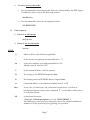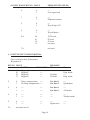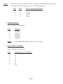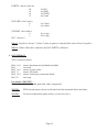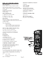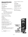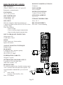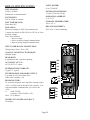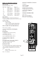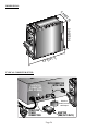
1
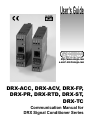
UserÕs Guide
®
http://www.omega.com
e-mail: [email protected]
DRX-ACC, DRX-ACV, DRX-FP,
DRX-PR, DRX-RTD, DRX-ST,
DRX-TC
Communication Manual for
DRX Signal Conditioner Series
omega.com
®
OMEGA®
OMEGAnet ® On-Line Service
http://www.omega.com
Internet e-mail
[email protected]
Servicing North America:
USA:
ISO 9001 Certified
Canada:
One Omega Drive, P.O. Box 4047
Stamford CT 06907-0047
TEL: (203) 359-1660
e-mail: [email protected]
976 Bergar
Laval (Quebec) H7L 5A1
TEL: (514) 856-6928
e-mail: [email protected]
FAX: (203) 359-7700
FAX: (514) 856-6886
For immediate technical or application assistance:
USA and Canada:
Mexico:
Sales Service: 1-800-826-6342 / 1-800-TC-OMEGA®
Customer Service: 1-800-622-2378 / 1-800-622-BEST®
Engineering Service: 1-800-872-9436 / 1-800-USA-WHEN®
TELEX: 996404 EASYLINK: 62968934 CABLE: OMEGA
TEL: (001)800-TC-OMEGA®
FAX: (001) 203-359-7807
En Español: (001) 203-359-7803
e-mail: [email protected]
Servicing Europe:
Benelux:
Czech Republic:
France:
Germany/Austria:
United Kingdom:
ISO 9002 Certified
Postbus 8034, 1180 LA Amstelveen, The Netherlands
TEL: +31 (0)20 3472121
FAX: +31 (0)20 6434643
Toll Free in Benelux: 0800 0993344
e-mail: [email protected]
Rudé armády 1868, 733 01 Karviná 8
TEL: +420 (0)69 6311899
FAX: +420 (0)69 6311114
e-mail: [email protected]
9, rue Denis Papin, 78190 Trappes
TEL: +33 (0)130 621 400
FAX: +33 (0)130 699 120
Toll Free in France: 0800406342
e-mail: [email protected]
Daimlerstrasse 26, D-75392 Deckenpfronn, Germany
TEL: +49 (0)7056 9398-0
FAX: +49 (0)7056 9398-29
Toll Free in Germany: 0800 TC-OMEGA®
e-mail: [email protected]
One Omega Drive
River Bend Technology Centre
Northbank, Irlam
Manchester M44 5EX United Kingdom
TEL: +44 (0) 161 777 6611
FAX: +44 (0) 161 777 6622
Toll Free in the UK: 0800 488 488
e-mail: [email protected]
It is the policy of OMEGA to comply with all worldwide safety and EMC/EMI regulations that apply.
OMEGA is constantly pursuing certification of its products to the European New Approach Directives.
OMEGA will add the CE mark to every appropriate device upon certification.
The information contained in this document is believed to be correct but OMEGA Engineering, Inc. accepts no liability for
any errors it contains, and reserves the right to alter specifications without notice.
WARNING: These products are not designed for use in, and should not be used for, patient connected applications.
This device is marked with the international hazard symbol. It is important to read the Setup Guide before
installing or commissioning this device as it contains important information relating to safety and EMC.
TABLE OF CONTENTS
I.
WHAT SIGNAL CONDITIONERS DO: . . . . . . . . . . . . . . . . . . . . . . . . . . . . . .
1
II.
MODEL OF UNIT : . . . . . . . . . . . . . . . . . . . . . . . . . . . . . . . . . . . . . . . . . . . . . . . . . . .
1
III.
RS485 SERIAL COMMUNICATION SETUP: . . . . . . . . . . . . . . . . . . . . . . . . .
1
SAFETY CONSIDERATIONS: . . . . . . . . . . . . . . . . . . . . . . . . . . . . . . . . . . . . . . . .
4
IV.
COMMANDS FOR ACCESSING EEPROM: . . . . . . . . . . . . . . . . . . . . . . . . . .
6
V.
DESCRIPTION OF DATA : . . . . . . . . . . . . . . . . . . . . . . . . . . . . . . . . . . . . . . . . . . .
7
VI.
COMMANDS FOR MEASUREMENT VALUES: . . . . . . . . . . . . . . . . . . . . . 16
VII.
COMMANDS FOR READING MODEL/INPUT TYPE: . . . . . . . . . . . . . . . 16
VIII.
RESET COMMANDS: . . . . . . . . . . . . . . . . . . . . . . . . . . . . . . . . . . . . . . . . . . . . . . . . 17
IX.
SAMPLE PROGRAM: . . . . . . . . . . . . . . . . . . . . . . . . . . . . . . . . . . . . . . . . . . . . . . . . 17
SPECIFICATIONS
DRX-ACC
. . . . . . . . . . . . . . . . . . . . . . . . . . . . . . . . . . . . . . . . . . . . . . . . . . . . . . . . . . . 19
DRX-ACV
. . . . . . . . . . . . . . . . . . . . . . . . . . . . . . . . . . . . . . . . . . . . . . . . . . . . . . . . . . . 20
DRX-FP
. . . . . . . . . . . . . . . . . . . . . . . . . . . . . . . . . . . . . . . . . . . . . . . . . . . . . . . . . . . . . 21
DRX-PR
. . . . . . . . . . . . . . . . . . . . . . . . . . . . . . . . . . . . . . . . . . . . . . . . . . . . . . . . . . . . . 22
DRX-RTD
. . . . . . . . . . . . . . . . . . . . . . . . . . . . . . . . . . . . . . . . . . . . . . . . . . . . . . . . . . . 23
DRX-ST
. . . . . . . . . . . . . . . . . . . . . . . . . . . . . . . . . . . . . . . . . . . . . . . . . . . . . . . . . . . . . 24
DRX-TC
. . . . . . . . . . . . . . . . . . . . . . . . . . . . . . . . . . . . . . . . . . . . . . . . . . . . . . . . . . . . . 25
ILLUSTRATIONS:
Dimensions
. . . . . . . . . . . . . . . . . . . . . . . . . . . . . . . . . . . . . . . . . . . . . . . . . . . . . . . . . . 26
Typical Computer Setup
. . . . . . . . . . . . . . . . . . . . . . . . . . . . . . . . . . . . . . . . . . . . 26
i
NOTES
ii
I. WHAT SIGNAL CONDITIONERS DO:
The DRX Series Signal Conditioners are high performance devices used as a front end for PLC’s and
Data Acquisition systems to measure a variety of low level transducer signals with high precision and
accuracy. The DRX Series Signal Conditioners interface directly to transducers and digitize the input
signal. The measured signal is then transmitted to a PLC or a computer using the RS485 Serial
Communication. Up to 32 units may be connected to the same serial RS485 bus, and each unit may
be addressed to transmit the signal being measured under program control, executed on a PLC or a
computer. The key features of the DRX Series Signal Conditioners are the ease of set-up and factory
calibrated ranges. All range switching are done electronically by sending the appropriate command;
therefore, there is no need to remove or open the units when signal input levels are changed. All setup may be done by using the Set-up Software running on a computer or by user supplied programs.
II. MODEL OF UNIT :
There are 7 models available:
THERMOCOUPLE
RTD
STRAIN
PROCESS
FREQUENCY/PULSE
AC VOLT
AC CURRENT
( DRX-TC )
( DRX-RTD )
( DRX-ST )
( DRX-PR )
( DRX-FP )
( DRX-ACV )
( DRX-ACC )
III. RS485 SERIAL COMMUNICATION SETUP:
Communication with the UNIT will be performed via serial communication using RS485 standard
(half duplex). To use the RS485 communication for the Signal Conditioners you’ll need an available
Communication port in your computer and have access to a generic communication software program
(e.g.: Procomm1, Windows2 HyperTerminal3, etc, see details below for information). A RS485 signal
conditioner communication software program is also available as an option to speed the set-up. A
RS232 to RS485 converter box will also be required if your computer communications port is RS232.
1
Procomm is a registered trademark of Datastorm Technologies, Inc.
2
Windows is a registered trademark of Microsoft Corp.
3
HyperTerminal is a registered trademark of Microsoft Corp.
Page 1
For Procomm:
Start the Procomm Program.
Press ALT + P (Select the appropriate communication parameters: Baud Rate, Parity, Data
Bits, Stop Bits.) The default settings may require modifications.
- Factory Default communication settings are as follows:
Baud Rate = 9600
Parity = Odd
Data Bits = 7
Stop Bits = 1
Press ALT + S (To save current communication settings)
Press ALT + O (To go to chat mode)
If the communication port selected is available and the communication parameters of both
the computer and the DRX are matched, then a serial link may be established. To check the
communication any of the commands may be tried i.e. *01X01 would return the current
measured signal value.
For Hyper Terminal (Windows 95):
Start the Hyper Terminal Program from programs/accessories.
Click on the Properties from the File menu.
Under the Phone Number Menu choose:
Connect using “Direct to COM1 or COM2” whichever that’s available.
Click on Configure Button.
Choose:
Baud rate, Data bits, Parity and Stop bits
According to DRX’s settings.
Flow Control = None.
Click “OK” Button.
- Factory Default communication settings are as follows:
Baud Rate = 9600
Parity = Odd
Data Bits = 7
Stop Bits = 1
Under Settings Menu:
Click ASCII Setup Button.
Choose all options except “Force Incoming Data to 7 Bits ASCII”.
Click “OK” Button.
Page 2
DRX -- SIGNAL CONDITIONERS WITH RS485
SERIAL COMMUNICATION PORT
RS232 TO
RS485 CONVERTER
HALF—DUPLEX
COMPUTER
SYSTEM GND
OR SHIELD
NOTE: YOU CAN CONNECT A DRX
DIRECTLY TO THE COMPUTER IF YOU
HAVE A RS485 COMMUNICATION
CARD INSTALLED IN THE COMPUTER.
TEE COUPLER
(JACKS SHOWN
FOR CLARITY)
CONNECT LAST
UNIT WITH
JUMPER TO
INCLUDE 120Ω
ON THE BUS
SHIELDED WIRE
DIN RAIL
FIRST UNIT ON BUS
LAST UNIT ON BUS
Communication Parameter Settings:
Communication settings information are very critical during set-up, if any of the parameters are
changed, it should be recorded on the label for future reference. If the communication parameters
used by the computer does not match the communication parameter of the DRX, then the
communication link may not be established. Hence it is important to record the communication
parameter on the label if different from default.
Resetting Communication Parameters to Factory Defaults
To restore the communication parameters to the factory default settings, two test points must be
shorted together. There are two ways of shorting these test points together, both are detailed below.
Version A-- Test point TP6 must be shorted, by a wire, to test point TP17.
or
Version B-- Newer units have a jumper position S1-A for connecting these two test points together.
Factory Default Settings for Communication:
Baud Rate = 9600
Data Bit = 7
Parity = Odd
Stop Bits = 1
Recognition Character = *
Address = 01
Page 3
SAFETY CONSIDERATIONS
This device is marked with the international Caution symbol. It is important to read
this manual before installing or commissioning this device as it contains important
information relating to Safety and EMC (Electromagnetic Compatibility).
Unpacking & Inspection
Unpack the instrument and inspect for obvious shipping damage. Do not attempt to
operate the unit if damage is found.
For instruments with AC Voltage and AC Current inputs, observe the input signal
connections in the appropriate section of this manual. These instruments must only
be installed by professional electricians.
•
•
•
•
•
•
Do not exceed voltage rating on the label located on the instrument housing.
Always disconnect power before changing signal and power connections.
Do not use this instrument on a work bench without its case for safety reasons.
Do not operate this instrument in flammable or explosive atmospheres.
Do not expose this instrument to rain or moisture.
Unit mounting should allow for adequate ventilation to ensure instrument does
not exceed operating temperature rating.
• Use electrical wires with adequate size to handle mechanical strain and power
requirements. Install without exposing bare wire outside the connector to
minimize electrical shock hazards.
EMC Considerations
•
•
•
•
Whenever EMC is an issue, always use shielded cables.
Never run signal and power wires in the same conduit.
Use signal wire connections with twisted-pair cables.
Install Ferrite Bead(s) on signal wires close to the instrument if EMC problems
persist.
Failure to follow all instructions and warnings may result in injury!
Page 4
SAFETY NOTE: Disconnect all signal input and outputs before attempting this procedure.
Instructions
1) Open the Signal Conditioner Unit—Remove Side Covers from Unit by lifting at the “angled
corners” first, using a flat-head screwdriver. Continue detaching remaining edges of the Cover.
2) Short TP6 & TP17 together, either by wire or, if available, jumper S1-A.
3) After shorting TP6 to TP17, apply power to the unit.
4) The Front Panel Power Indicator (LED) will NOT turn on.
5) After power has been applied to the unit for about 30 seconds, turn power off.
6) The communication parameters now have been restored to the default settings.
7) Use the DRX Set-up Program to establish communication with the meter.
8) This procedure will not affect calibration. It only resets the communication parameters.
Lift Cover at Angled Corners.
Side Cover
Remove to
Access
Testpoints.
Front Panel
Side Cover
Remove to
Access S1-A
Jumper
Lift Cover at Angled Corners.
Six Attachments Per Side
Opening Unit
Solder wire from
TP6 to TP17 on
Solder side of Board.
Install Jumper onto
S1-A on Component
Side of Board.
Version A
Version B
Testpoint/Jumper Locations
Page 5
IV.
COMMANDS FOR ACCESSING EEPROM:
NO.
command letter index
1.
2.
3.
4.
5.
6.
7.
8.
9.
10.
11.
12.
13.
14.
15.
R,W
R,W
R,W
R,W
R,W
R,W
R,W
R,W
R,W
R,W
R,W
R,W
R,W
R,W
R,W
01
02
03
04
05
06
07
08
09
0A
0B
0C
0D
0E
0F
meaning
# of bytes
Input range or function
Input/output Configuration
Decimal point
Filter time constant
Reading scale
Reading offset
Communication parameters
Communication bus format
Communication Data format
Communication device address
Communication recog. char.
Unit of measure
Gate time
Debounce time
Transmit time
1
1
1
1
3
3
1
1
1
1
1
3
1
1
2
NOTE:
A.
1.
Data (Number of hex digits) = 2 * number of bytes
2.
command letter
R
W
3.
"W" commands should be followed by "Z01" command for new values to take effect.
meaning
Read from EEPROM
Write to EEPROM
COMMAND FORMAT (TRANSMITTING):
*[nn]Cxx[data][hh]<cr>
Note: Data is required if Command Letter is “W”
B.
RESPONSE FORMAT (RECEIVING):
A.
Correct response :
1.
If unit is in echo mode* (see "BUS FORMAT") :
[nn]Cxx[data][hh]<cr>
*echo mode = unit will send back the command.
Page 6
2.
If unit is not in echo mode :
i. For the commands which require the data to be transmitted by the DRX Signal
Conditioner, data is sent in the following formats:
data[hh]<cr>
ii. For the commands which do not require the data:
NO RESPONSE
B.
Error response:
1. If unit is in echo mode:
[nn]?ee<cr>
2. If unit is not in echo mode:
?ee<cr>
NOTE :
[]
:
Means will be used wherever applicable.
*
:
Is the security recognition character(default is “*”).
nn
:
Is the unit's address in hexadecimal(default is 01).
Address may be from 01 to FF.
C
:
Is the command letter ( must be capital ).
W
:
For writing to the EEPROM (requires data)
R
:
For reading from the EEPROM (doesn’t require data)
xx
:
Command index is a hexadecimal number from 01 to FF.
data
:
Is one, two, or three bytes (2,4,6 characters respectively). It will be in
hexadecimal format except when command "X" is executed in which case it
is in decimal format.
hh
:
Is checksum characters
( Required if Checksum option is on. See “BUS FORMAT”).
The checksum is one byte (two characters) that is the simple hexadecimal
addition of all the previous bytes, ignoring any overflow.
Page 7
?ee
<cr>
Note:
V.
:
Special code indicating an error has occurred as:
?43
:
Command error
( occurs if command letters and indexes are invalid)
?46
:
Format error
( occurs if length of the data or number of characters is not correct )
?48
:
Checksum error
( occurs if checksum is not correct )
?50
:
Parity error
( occurs if parity is not correct )
:
Carriage return
If Baud rate, Recognition character or address are not correct then the UNIT will not
respond.
DESCRIPTION OF DATA :
For the following Bit Pattern. The LSB is always bit 0. Bit numbers are always counted from
right to left, with the rightmost digit being bit 0, and the next to the left would be bit 1.
1. INPUT RANGE:
This is one byte data (2 characters). This byte will specify input range and other input
configurations of each model. Bit pattern for different models :
a. INPUT RANGE BYTE VALUE
TC
Bits:3210
0000
J
0001
K
0010
T
0011
E
0100
N
0101
DIN J
0110
R
0111
S
1000
B
(1001-1111 not used )
Bit 6-4: not used
Bit 7:
0
1
Line frequency = 60Hz
Line frequency = 50Hz
Page 8
ACV
ACC
400 mV ac
4 V ac
40 V ac
400 V ac
----------------
10 mA
100 mA
1A
5A
----------------
b. INPUT RANGE BIT NO. VALUE
Bits:
1-0
00
01
10
11
2
0
1
3
0
1
00
01
10
11
5-4
RTD
100 ohms
500 ohms
1000 ohms
10 ohms COPPER
PLATINUM
NICKEL
DIN STANDARD
NIST FOR Pt (SAMA FOR Ni)
2 wire
3 wire
4 wire
not used
6
7
not used
0
1
Line frequency = 60Hz
Line frequency = 50Hz
c. INPUT RANGE BIT NO. VALUE
3-0
0000
0001
0010
0011
0100
0101
(0110 - 1111 not used)
PROCESS (PR)
STRAIN (ST)
0-20 mA
400 mV
1V
2V
5V
10 V
30 mV
100 mV
---------
Internal excit.
External excit.
4
0
1
14V Excit.
10V Excit.
5
0
1
Non-ratiometric (PR,ST)
Ratiometric (PR,ST)
6
not used
7
0
1
Line frequency = 60Hz(PR,ST)
Line frequency = 50Hz(PR,ST)
Page 9
d. INPUT RANGE BIT NO. VALUE
FREQUENCY/PULSE (FP)
0
0
1
---Low input level
1
0
1
---Debounce contact
2
0
1
---3K pull up to 5V
3
0
1
---1K pull down
5-4
00
01
10
11
12.5V excit.
5V excit.
8V excit.
not used
7-6
not used
2. INPUT/OUTPUT CONFIGURATION:
This is one byte data (2 characters).
Bit pattern is:
BIT NO. VALUE
TC/RTD
1-0
00
Degree C
01
Degree F
10
Degree K
11
Degree K
ACV/ACC/ST
-------------
MEANING
PR
Totalizer
Totalizer
FP
---Freq. mode
---Freq. mode
2
0
1
Temp. compensation ---No temp compensation ----
See Note 1
See Note 1
---Quadrature
3
0
1
-------
-------
See Note 1
See Note 1
---A-B mode
4
0
1
-------
-------
-------
---Totalize mode
5
0
1
-------
-------
---Square root
-------
7-6
not used set to 0
Page 10
Note 1:
Bit 2&3 set the speed of process totalize. The time it would take process totalize to
reach the non-totalize reading is shown in the following table:
Bit 3
Bit 2
0
0
1
1
0
1
0
1
Time to reach regular reading
1 minute
1 hour
1 day
30 day
3. DECIMAL POINT :
This is one byte (2 characters) as:
value
1
2
3
4
5
6
meaning
XXXXXX.
XXXXX.X
XXXX.XX
XXX.XXX
XX.XXXX
X.XXXXX
Note 1:
For TC and RTD models, value must be 1 to 3 only.
4. FILTER TIME CONSTANT:
This is one byte (2 characters) as:
value
0
1
2
3
4
5
6
7
meaning (per no. of readings)
No filtering
2
4
8
16
32
64
128
Page 11
5. READING SCALE:
Multiplication factor applied to input to get a higher or lower reading.
This is 3 byte data (6 characters) as follows:
- Bits 0 to 18 (19 bits) are value of the scale from 0 to 500000
- Bit 19 is sign, 0 for positive and 1 for negative
- Bits 20 to 23 are for decimal point value = DP
It means as:
Actual decimal value = 10 ** ( 1 - DP )
where ** means "TO THE POWER OF"
example: if scale is -0.000345678.= - 345678 x 10**(-9)
value will be 345678 decimal = 5464E hex
bit 19 =1 for negative
bits 20-23 = DP = 10 = A hex
then data will be AD464E hex
6. READING OFFSET:
Deviation applied to input to get a higher or lower reading.
This is 3 byte data (6 characters) as follows:
- Bits 0 to 19 are value from 0 to 1000000
- Bit 23 is sign, 0 for positive, 1 for negative
- Bits 20,21,22 are decimal point value = DP
It means as :
Actual decimal value = 10 ** ( 2 - DP )
where ** means "TO THE POWER OF"
example: offset value is 234.089
value of 234089 decimal = 39269 hex
decimal value = 10 ** (-3) then DP=5
then 234.089 decimal = 539269 hex
7. COMMUNICATION PARAMETERS:
This is one byte data and specifies
BAUD, PARITY, DATA, and STOP bit.
BAUD =
bits 2,1,0 are:
000-001
not used
010
for 1200
011
for 2400
100
for 4800
101
for 9600
110
for 19200
111
not used
Page 12
PARITY = bits 4,3 and are:
00
01
10
11
for NO
for ODD
for EVEN
not used
DATA BIT = bit 5 and is:
0
1
for 7 data
for 8 data
STOP BIT = bit 6 and is:
0
1
Bit 7 : always 0
for 1 stop
for 2 stop
Note 1: Stop bit is always 1. Unless 7 data, no parity is selected then unit will use 2 stop bits.
Note 2: When 8 Data bit is selected, only NO PARITY is allowed.
8. BUS FORMAT:
This is one byte data as:
Bit 0 = 0/1
Bit 1
Bit 2 = 0/1
Bit 3 = 1
Bit 4 = 0/1
Bits 7-5
means checksum not included/included
not used
means no echo/echo
means 485 mode
means continuous/command mode
not used
For models (PR/ST/FP):
Bit 7 = 0/1 Enable/Disable peak and valley comparison
NOTE 1 :
ECHO mode means the unit will echo back the command letter and index.
NOTE 2 :
Do not use checksum option unless you have to use it.
Page 13
9. DATA FORMAT:
This is one byte and specifies the data which will be transmitted against the
"V01" command.
Bit pattern:
bit 0 = 0/1
Means do not include/include peak & valley status register.
bit 1 = 0/1
Means do not include/include reading.
bit 2 = 0/1
For models(TC/RTD/ACV/ACC):
Means do not include/include peak reading.
bit 2 = 0/1
For models(PR/ST):
Means do not include/include process totalize.
bit 3 = 0/1
For models(TC/RTD/ACV/ACC):
Means do not include/include valley reading.
bit 3 = 0/1
For models(PR/ST/FP):
Means do not include/include peak reading.
bits 4
For models(TC/RTD/ACV/ACC):
Not used. Set to 0.
bits 4 = 0/1
For models(PR/ST/FP):
Means do not include/include valley reading.
bit 5
Not used. Set to 0.
bit 6 = 0/1
Means do not include/include unit of measure.
bit 7 = 0/1
Means space/carriage return between values.
10. DEVICE ADDRESS :
This is one byte data and specifies the address of the unit when in RS485 multipoint mode.
Addresses are in hexadecimal from 01 to FF.
NOTE:
Address 00 is for broadcasting. All units on the same BUS will perform any
command with this address but will not respond.
11. RECOGNITION CHARACTER:
This is one byte security character.
(Default is *)
Page 14
12. UNIT OF MEASURE:
This is 3 bytes. It is ASCII value of unit of measure.
13. GATE TIME(For FP model only):
This is 1 byte from 00 to FF.
For value = 00 to FA:
Each count equals 10ms. If 0 then gate time = 3ms.
Example : 1 second gate time = 64 hex.
For value = FB to FF:
Value
FB
FC
FD
FE
FF
Gate time
5 seconds
10 seconds
20 seconds
40 seconds
80 seconds
14. DEBOUNCE TIME(For FP model only):
This is 1 byte from 01 to FF.
Each count equals 5ms. If 0 then error.
15. TRANSMIT TIME:
This is 2 bytes data in second and specifies the time of the transmission by the meter.
Page 15
VI.
COMMANDS FOR MEASUREMENT VALUES:
Command
Receiving value
*01X01
(For all models):
Note:
In order to have continuous update on reading. Customer
should send X01 command every time reading is requested.
Reading value. After reading scale and offset.
Models(TC/RTD/ACV/ACC):
*01X02
Peak reading value.
*01X03
Valley reading.
Models(PR/ST/FP):
*01X03
Peak reading value.
*01X04
Valley reading.
*01V01
(For all models): String of values.
Received values are in decimal with decimal point and no sign for positive and minus sign
for negative.
Example :
00345.6 or -00345.6
If value is overflowed a “?” will be transmitted along with value (?-99999. or ?999999).
VII. COMMANDS FOR READING MODEL/INPUT TYPE:
Command
Receiving value
*01U01
One byte for model number
VALUE
00
01
02
03
04
05
06
MODEL
FP
PR
ST
TC
RTD
ACV
ACC
Page 16
VIII. RESET COMMANDS :
*01Z01 (For all models): Hard reset (reading data from EEPROM).
*01Z02 (For all models): Soft reset (Initialize reading).
*01Z03 (For models: TC/RTD/ACV/ACC): Reset peak and valley.
(For models: PR/ST): Reset process totalize value.
*01Z04 (For models: (PR/ST/FP): Reset peak value.
*01Z05 (For models: PR/ST/FP): Reset valley value.
*01Z07 (For models: TC/RTD/ACV/ACC): Reset peak only.
*01Z08 (For models: TC/RTD/ACV/ACC): Reset valley only.
NOTE:
*
01(Follow “*”)
IX.
: Recognition character
: Address
SAMPLE PROGRAM:
' ASSUMING :
' BAUD RATE = 9600
' PARITY
= ODD
' DATA BIT = 7
' STOP BIT = 1
' COMM PORT = 1
' ADDRESS
= 01
' RECOG. CHAR = *
' SERIAL PORT = COM1
' FOR COMM PORT = 2 -> CHANGE "COM1:" TO "COM2:"
' THIS PROGRAM WILL GET READING AND DISPLAY IT EVERY 1 SECOND
ON ERROR GOTO ER
ON TIMER(1) GOSUB RDG
CLS
CLOSE #1
COLOR 1, 7
LOCATE 22, 30
PRINT "PRESS <ESC> TO END"
OPEN "COM1:" + "9600,O,7,1,CS,DS" FOR RANDOM AS #1
LOCATE 10, 30
PRINT "READING = "
TIMER ON
DO: LOOP UNTIL INKEY$ = CHR$(27)
Page 17
COLOR 7, 0
CLS
END
RDG:
PRINT #1, "*01X01"
DAT1$ = ""
DAT$ = ""
T$ = TIME$
T1$ = MID$(T$, LEN(T$) - 1, 2)
T1 = VAL(T1$)
DO
IF LOC(1) > 0 THEN
CNT = 0
DAT1$ = INPUT$(LOC(1), #1)
DAT$ = DAT$ + DAT1$
ELSE
T$ = TIME$
T2$ = MID$(T$, LEN(T$) - 1, 2)
T2 = VAL(T2$)
IF T2 < T1 THEN T2 = T2 + 60
IF T2 - T1 >= 2 THEN CNT = 1
END IF
LOOP UNTIL CNT = 1 OR INSTR(1, DAT$, CHR$(13)) > 0
IF DAT$ = "" THEN
LOCATE 5, 30
COLOR 28
PRINT "COMMUNICATION ERROR!"
P = 1
ELSE
IF P = 1 THEN
LOCATE 15, 30
COLOR 7, 0
PRINT "
"
' (24 SPACES)
P = 0
END IF
LOCATE 10, 40
D$ = MID$(DAT$, 6)
DAT$ = LEFT$(D$, LEN(D$) - 1)
COLOR 1, 7
PRINT DAT$; " "
' (2 SPACES)
END IF
RETURN
ER:
RESUME NEXT
Page 18
DRX-ACC SPECIFICATIONS
INPUT RANGES:
10 mA, 100 mA, 1 Amp, 5 Amp AC current
Dedicated input terminals for (10, 100 mA same
input), 1 Amp and 5 Amp. Return terminal common
to all ranges.
WARM UP TO RATED ACCURACY:
30 minutes
INPUT POWER:
10 to 32 Volt DC
POWER CONSUMPTION:
2.4 Watts (100 mA at 24 V DC)
FREQUENCY RANGE:
30 Hz to 1KHz
OPERATING AMBIENT:
-5 to +55 °C
INPUT IMPEDANCE:
3.3 Ohms for 10, 100 mA input
0.2 Ohms for 1 Amp input
0.04 Ohms for 5 Amp input
STORAGE TEMPERATURE:
-40 to +85 °C
RELATIVE HUMIDITY:
90% at 40 °C non-condensing
ISOLATION:
Dielectric strength to 1000 Vrms transient per
1 minute test based on EN 61010 for 50 Vdc or Vrms
working voltage.
Three way Isolation:
• Power to input
• Power to analog output/communication
• Input to analog output/communication
INPUT OVER-CURRENT PROTECTION:
10% Above full scale continuously
100% Above full scale for 10 seconds
ANALOG TO DIGITAL TECHNIQUE:
Dual slope
READ RATE:
3 readings/second
ACCURACY AT 25 °C:
± 0.2% of FS from 30 Hz to 1 KHz
TEMPERATURE STABILITY:
10, 100 mA Range 100 ppm/°C typical
1 Amp Range 150 ppm/°C typical
5 Amp Range 200 ppm/°C typical
STEP RESPONSE FOR RS485 OUTPUT:
2 seconds to 99% of the final value
(Filter time constant = 64)
RESPONSE TIME:
To verify the response time, check the carriage return
<CR>, it will be sent at the end of the response. You
can send another command after you receive the
<CR>.
i.e.
send: *01X01
response: 01X01<DATA><CR>
Note: 01 is address.
Page 19
RETURN
5A
1A
100mA
{
1
2
SIGNAL INPUT
D
C
+
-
N/C
P
W
R
WARM UP TO RATED ACCURACY:
30 minutes
DRX-ACV SPECIFICATIONS
INPUT RANGES:
400 mV, 4V, 40 Volt, 400 Volt
INPUT POWER:
10 to 32 Volt DC
FREQUENCY RANGE:
30 Hz to 1 KHz
POWER CONSUMPTION:
2.4 watts (100 mA at 24 Vdc)
INPUT IMPEDANCE:
2.1 Meg for all ranges.
ISOLATION:
Dielectric strength to 1000 Vrms transient per
1 minute test based on EN 61010 for 50 Vdc or Vrms
working voltage.
Three way Isolation:
• Power to input
• Power to analog output/communication
• Input to analog output/communication
OPERATING AMBIENT:
-5 to +55 °C
STORAGE TEMPERATURE:
-40 to +85 °C
RELATIVE HUMIDITY:
90% at 40 °C non-condensing
INPUT OVER-VOLTAGE PROTECTION:
10% Above full scale continuously.
100% Above full scale for 10 seconds.
ANALOG TO DIGITAL TECHNIQUE:
Dual slope
READ RATE:
3 readings/second
ACCURACY AT 25 °C:
400 mV, 4V, 40V and 400V ranges
49 Hz to 500 Hz ±0.2% of FS
30 Hz to 1KHz ±0.2% of FS ±10 counts
TEMPERATURE STABILITY:
400 mV and 40 Volt range 150 ppm/°C typical
4V and 400 Volt range 100 ppm/°C typical
STEP RESPONSE FOR RS485 OUTPUT:
2 seconds to 99% of the final value
(Filter time constant = 64)
RESPONSE TIME:
To verify the response time, check the carriage return
<CR>, it will be sent at the end of the response. You
can send another command after you receive the
<CR>.
i.e.
send: *01X01
response: 01X01<DATA><CR>
Note: 01 is address.
Page 20
+
SIG HI
N/C
N/C
SIG LO
1
2
SIGNAL INPUT
D
C
+ -
P
N/C W
R
DRX-FP SPECIFICATIONS
FREQUENCY
0 to 9.99999 Hz
10 to 99.9999 Hz
100 to 999.999 Hz
1000 to 9999.99 Hz
10000 to 50000.0 Hz
0 to 50000 Hz
RTN
+IN
INPUT TYPE:
Min. Low level signal input (magnetic
120mV
pickups) : From 0 mV to 120 mV
ø
Open Collector NPN (Use software to set:
3 KΩ pull up to 5V): Max. current source = 1.66 mA
Open Collector PNP (Use software to set: 1KΩ pull down to RTN):
Max. current sink = 12.5 mA
TTL/CMOS Input: (Use software to set: no pull up/down).
Low <= 0.8 V , High >= 3.5 V (For Input: 0.2 Hz to 16 KHz)
Low <= 0.8 V , High >= 12 V ( For Input: 0.2 Hz to 50 KHz )
NAMUR Sensors (Use software to set: 1KΩ pull
down to RTN and 8.2V Excitation.)
1
2
3
4
For measuring a low level signal riding on top of a
large DC signal, connect a 0.1 uF capacitor. See
Detail.Use software to set 1KΩ pull down to RTN.
0.1uF
OPERATING MODES:
Frequency: Range = 0.2 Hz to 50 KHz
Max. Input Frequency: 30 KHz. for Input Level: 0-5 V
Max. Input Frequency: 50 KHz. for Input Level: 0-12 V
RESOLUTION
0.00001 Hz
0.0001 Hz
0.001 Hz
0.01 Hz
0.1 Hz
1 Hz
Totalize with Reset: Range = 0 to 999999*, if reading is larger
than 999999, then reading is converted to floating point
number, i.e. 9.99E9 (maximum).
Max. Input Frequency: 30 KHz. for Input Level: 0-5 V
Max. Input Frequency: 50 KHz. for Input Level: 0-12 V
A-B Totalize (Reset input used as +A input): Range = -99999
to 999999*, if reading is larger than 999999, then reading is
converted to floating point number, i.e. -9.99E9 (minimum),
9.99E9 (maximum).
Max. Input Frequency: 30 KHz. for Input Level: 0-5 V
Max. Input Frequency: 25 KHz. for Input Level: 0-12 V
Quadrature (Reset input used as second input): Range =
-99999 to 999999*, if reading is larger than 999999, then reading
is converted to floating point number, i.e. -9.99E9 (minimum),
9.99E9 (maximum).
Max. Input Frequency: 30 KHz. for Input Level: 0-5 V
Max. Input Frequency: 25 KHz. for Input Level: 0-12 V
* Resolution is 1 count.
INPUT OVER-VOLTAGE PROTECTION:
With 1K pull down: 14V
With 3K pull up: 20V
Without pull up/down: 60V
EXCITATION:
5, 8.2 or 12.5V at 25mA, programmable
ACCURACY AT 25 °C:
± 0.1% of FS Crystal time base accuracy: ± 50 ppm
TEMPERATURE STABILITY:
± 50 ppm/°C typical
Time base stability: ± 1ppm/°C
STEP RESPONSE FOR RS485 OUTPUT:
0.1 second to 99% of the final value
(Filter time constant = 0, Gate time = 0.05 Sec)
RESPONSE TIME:
To verify the response time, check the carriage return <CR>, it will be
sent at the end of the response. You can send another command after
you receive the <CR>.
i.e.
send: *01X01
response: 01X01<DATA><CR>
Note: Only for reading (X01 command).
01 is address.
Frequency mode: response time is controlled by the gate time. If
gate time is increased then response time is longer. Other modes:
response time is not controlled by the gate time.
WARM UP TO RATED ACCURACY:
30 minutes
INPUT POWER:
10 to 32 Volt DC
POWER CONSUMPTION:
3 Watts (125mA at 24V DC)
OPERATING AMBIENT:
-5 to +55 °C
STORAGE TEMPERATURE:
-40 to +85 °C
RELATIVE HUMIDITY:
90% at 40 °C non-condensing
J4
J1
Quadrature Mode
+EXC
+IN
RST
RTN
Excitation
A
B
Quadrature
Encoder
ISOLATION:
Dielectric strength to 1000 Vrms transient per 1 minute test
based on EN 61010 for 50 Vdc or Vrms working voltage.
Three way Isolation:
• Power to input
• Power to analog output/communication
• Input to analog output/communication
EXC
EXC
A
+EXC
+IN
RST
RTN
1
2
3
R
-TX +TX
S
-RX +RX TER 4
4
J2
8
5
1
2
3
4
J2
PWR
Totalize (A-B) Mode
B
Frequency Mode/
Totalize Mode
with Reset (example)
1
Excitation
INPUT IMPEDANCE:
Input: 1MΩ to +EXC
Reset: 100K to +5V
R
S
4
8
5
J3
NPN open
Collector
+EXC
+IN
RST
RTN
2
3
4
J2
SIGNAL INPUT
D
C
+ -
Page 21
J1
Quadrature Mode
P
N/C W
R
WARM UP TO RATED ACCURACY:
30 minutes
DRX-PR SPECIFICATIONS
INPUT RANGES:
±20mA; ±400mV, ±1V, ±2V, ±5V, and ±10V
Ratiometric or nonratiometric
INPUT POWER:
10 to 32 Volt DC
EXCITATION:
14V or 10V @ 25mA
POWER CONSUMPTION:
3 watts (125 mA at 24Vdc)
INPUT IMPEDANCE:
Voltage Range: 1MΩ
Current Range: 10Ω
OPERATING AMBIENT:
-5 to +55 °C
STORAGE TEMPERATURE:
-40 to +85 °C
ISOLATION:
Dielectric strength to 1000 Vrms transient per
1 minute test based on EN 61010 for 50 Vdc or Vrms
working voltage.
Three way Isolation:
• Power to input
• Power to analog output/communication
• Input to analog output/communication
RELATIVE HUMIDITY:
90% at 40 °C non-condensing
J4
INPUT OVER-RANGE PROTECTION:
R
-TX +TX
S
-RX +RX TER 4
Voltage input: 50V
Current input: 50mA
8
5
MODE:
Linear, Square root, Linear totalize,
Square root totalize
PWR
R
S
4
8
5
J3
ANALOG TO DIGITAL TECHNIQUE:
Multiple slopes
READ RATE:
8 readings/second, automatic polarity
ACCURACY AT 25 °C:
±0.1% of FS ± 2 counts
+
+ +
1
+ EXC
+ V IN
+ I IN
- - -
RTN
TEMPERATURE STABILITY:
100 ppm/°C typical
2
3
4
J2
SIGNAL INPUT
D
C
+
STEP RESPONSE FOR RS485 OUTPUT:
2 seconds to 99% of the final value
(Filter time constant = 64)
P
-
N/C W
R
J1
Excitation
RESPONSE TIME:
To verify the response time, check the carriage return
<CR>, it will be sent at the end of the response. You
can send another command after you receive the
(+ )
<CR>.
MAX.
20mA
i.e.
send: *01X01
( )
response: 01X01<DATA><CR>
Note: 01 is address.
-
Page 22
SIG
+ EXC
+ V IN
+ I IN
1
2
3
4
J2
RTN
COM
+ EXC
+ V IN
+ I IN
1
2
3
4
+ EXC
+ V IN
+ I IN
J2
RTN
(4-20)
-+ +
( )
( )
RTN
1
2
3
4
J2
POWER CONSUMPTION:
2.4 Watts (100 mA at 24 V DC)
DRX-RTD SPECIFICATIONS
SPECIFICATIONS:
100, 500, 1000 Ohm platinum RTD with both
European (alpha=0.00385) and American
(alpha=0.00392) curves.
Input Type:
100 Ohm
-328 to 1562 °F
500 Ohm
-328 to 1562 °F
1000 Ohm
-328 to 1562 °F
OPERATING AMBIENT:
-5 to +55 °C
STORAGE TEMPERATURE:
-40 to +85 °C
-200 to 850 °C
-200 to 850 °C
-200 to 850 °C
RELATIVE HUMIDITY:
90% at 40 °C non-condensing
ISOLATION:
Dielectric strength to 1000 Vrms transient per
1 minute test based on EN 61010 for 50 Vdc or Vrms
working voltage.
Three way Isolation:
• Power to input
• Power to analog output/communication
• Input to analog output/communication
J4
R
-TX +TX
S
-RX +RX TER 4
8
5
INPUT OVER-VOLTAGE PROTECTION:
250 V AC for 1 Minute
PWR
ANALOG TO DIGITAL TECHNIQUE:
Dual slope
R
S
4
8
5
J3
READ RATE:
3 readings/second, automatic polarity
ACCURACY AT 25 °C:
±0.5 °C for platinum RTD’s
2 WIRE
TEMPERATURE STABILITY:
0.05 °C/°C
RTD
+EXC
+SIG
-SIG
-EXC
1
2
3
4
J2
STEP RESPONSE FOR RS485 OUTPUT:
2 seconds to 99% of the final value
(Filter time constant = 64)
SIGNAL INPUT
RESPONSE TIME:
To verify the response time, check the carriage return
<CR>, it will be sent at the end of the response. You
can send another command after you receive the <CR>.
i.e.
send: *01X01
response: 01X01<DATA><CR>
Note: 01 is address.
+ -
D
C
+EXC
+SIG
-SIG
-EXC
RTD
4 WIRE
RTD
Page 23
R
J1
3 WIRE
WARM UP TO RATED ACCURACY:
30 minutes
INPUT POWER:
10 to 32 Volt DC
P
N/C W
+EXC
+SIG
-SIG
-EXC
1
2
3
4
J2
1
2
3
4
J2
INPUT POWER:
10 to 32 Volt DC
DRX-ST SPECIFICATIONS
INPUT RANGE:
±30mV/ ±100mV
Ratiometric or nonratiometric
POWER CONSUMPTION:
3 watts (125 mA at 24Vdc)
EXCITATION:
10V @ 30mA or external
OPERATING AMBIENT:
-5 to +55 °C
INPUT IMPEDANCE:
More than 1MΩ
STORAGE TEMPERATURE:
-40 to +85 °C
ISOLATION:
Dielectric strength to 1000 Vrms transient per
1 minute test based on EN 61010 for 50 Vdc or Vrms
working voltage.
Three way Isolation:
• Power to input
• Power to analog output/communication
• Input to analog output/communication
RELATIVE HUMIDITY:
90% at 40 °C non-condensing
J4
INPUT OVER-RANGE PROTECTION:
R
-TX +TX
S
-RX +RX TER 4
Voltage input: From -10 to +20V
ANALOG TO DIGITAL TECHNIQUE:
Multiple slopes
8
5
READ RATE:
8 readings/second, automatic polarity
+EXC
ACCURACY AT 25 °C:
±0.2% of FS ± 2 counts
+SIG
PWR
J3
R
S
4
8
5
-SIG
TEMPERATURE STABILITY:
75 ppm/°C typical
-EXC
STEP RESPONSE FOR RS485 OUTPUT:
2 seconds to 99% of the final value
(Filter time constant = 64)
RESPONSE TIME:
To verify the response time, check the carriage return
<CR>, it will be sent at the end of the response. You
can send another command after you receive the
<CR>.
i.e.
send: *01X01
response: 01X01<DATA><CR>
Note: 01 is address.
WARM UP TO RATED ACCURACY:
30 minutes
Page 24
+EXC
+SIG
-SIG
-EXC
1
2
3
J2
SIGNAL INPUT
D
C
V+ (external)
+EXC
+SIG
-SIG
-EXC
4
+
J1
P
N/C W
R
WARM UP TO RATED ACCURACY:
30 minutes
DRX-TC SPECIFICATIONS
INPUT TYPE:
Type J,K,T,E,R,S,B,N, J DIN
Input Type Range °F
J
-346 to 1400°F
K
-454 to 2500°F
T
-454 to 752 °F
E
-454 to 1832 °F
RS
-58 to 3214 °F
B
+212 to 3300 °F
N
-454 to 2372°F
J DIN
-328 to 1652 °F
INPUT POWER:
10 to 32 Volt DC
Range °C
-210 to 760 °C
-270 to 1372 °C
-270 to 400 °C
-270 to 1000 °C
-50 to 1768 °C
+100 to 1820 °C
-270 to 1300 °C
-200 to 900 °C
POWER CONSUMPTION:
2.4 Watts (100 mA at 24 V DC)
OPERATING AMBIENT:
-5 to +55 °C
STORAGE TEMPERATURE:
-40 to +85 °C
ISOLATION:
Dielectric strength to 1000 Vrms transient per
1 minute test based on EN 61010 for 50 Vdc or Vrms
working voltage.
Three way Isolation:
• Power to input
• Power to analog output/communication
• Input to analog output/communication
RELATIVE HUMIDITY:
90% at 40 °C non-condensing
INPUT OVER-VOLTAGE PROTECTION:
R
-TX +TX
S
-RX +RX TER 4
8
5
250 V AC for 1 minute
ANALOG TO DIGITAL TECHNIQUE:
Dual slope
READ RATE:
3 readings/second, automatic polarity
PWR
ACCURACY AT 25 °C:
±1°C for temperature above -150 °C
±2°C for temperature below -150 °C
R
S
4
8
5
TEMPERATURE STABILITY:
0.05 °C/°C
STEP RESPONSE FOR RS485 OUTPUT:
2 seconds to 99% of the final value
(Filter time constant = 64)
RESPONSE TIME:
To verify the response time, check the carriage return
<CR>, it will be sent at the end of the response. You
can send another command after you receive the
<CR>.
i.e.
send: *01X01
response: 01X01<DATA><CR>
Note: 01 is address.
Page 25
DIMENSIONS:
0.
89
[2
2.
5]
2.95[75.0]
PW
R
.1]
[121
4.77
TYPICAL COMPUTER SETUP:
COMPUTER
CONNECTION
(DB9 OR DB25)
RJ12 CONNECTOR
WITH CABLE
PW
R
RS232 to
RS485 Converter
Half-Duplex
COMPUTER
POWER
CONNECTION
ADAPTER
(DB9/25 TO RJ12)
Page 26
WARRANTY/DISCLAIMER
OMEGA ENGINEERING, INC. warrants this unit to be free of defects in materials and workmanship for a
period of 13 months from date of purchase. OMEGA Warranty adds an additional one (1) month grace
period to the normal one (1) year product warranty to cover handling and shipping time. This
ensures that OMEGA’s customers receive maximum coverage on each product.
If the unit should malfunction, it must be returned to the factory for evaluation. OMEGA’s Customer
Service Department will issue an Authorized Return (AR) number immediately upon phone or written
request. Upon examination by OMEGA, if the unit is found to be defective it will be repaired or replaced at
no charge. OMEGA’s WARRANTY does not apply to defects resulting from any action of the purchaser,
including but not limited to mishandling, improper interfacing, operation outside of design limits,
improper repair, or unauthorized modification. This WARRANTY is VOID if the unit shows evidence of
having been tampered with or shows evidence of being damaged as a result of excessive corrosion; or
current, heat, moisture or vibration; improper specification; misapplication; misuse or other operating
conditions outside of OMEGA’s control. Components which wear are not warranted, including but not
limited to contact points, fuses, and triacs.
OMEGA is pleased to offer suggestions on the use of its various products. However,
OMEGA neither assumes responsibility for any omissions or errors nor assumes liability for any
damages that result from the use of its products in accordance with information provided by
OMEGA, either verbal or written. OMEGA warrants only that the parts manufactured by it will be
as specified and free of defects. OMEGA MAKES NO OTHER WARRANTIES OR
REPRESENTATIONS OF ANY KIND WHATSOEVER, EXPRESSED OR IMPLIED, EXCEPT THAT OF
TITLE, AND ALL IMPLIED WARRANTIES INCLUDING ANY WARRANTY OF MERCHANTABILITY
AND FITNESS FOR A PARTICULAR PURPOSE ARE HEREBY DISCLAIMED. LIMITATION OF
LIABILITY: The remedies of purchaser set forth herein are exclusive and the total liability of
OMEGA with respect to this order, whether based on contract, warranty, negligence,
indemnification, strict liability or otherwise, shall not exceed the purchase price of the
component upon which liability is based. In no event shall OMEGA be liable for
consequential, incidental or special damages.
CONDITIONS: Equipment sold by OMEGA is not intended to be used, nor shall it be used: (1) as a “Basic
Component” under 10 CFR 21 (NRC), used in or with any nuclear installation or activity; or (2) in medical
applications or used on humans. Should any Product(s) be used in or with any nuclear installation or
activity, medical application, used on humans, or misused in any way, OMEGA assumes no responsibility
as set forth in our basic WARRANTY/ DISCLAIMER language, and additionally, purchaser will indemnify
OMEGA and hold OMEGA harmless from any liability or damage whatsoever arising out of the use of the
Product(s) in such a manner.
RETURN REQUESTS / INQUIRIES
Direct all warranty and repair requests/inquiries to the OMEGA Customer Service Department. BEFORE
RETURNING ANY PRODUCT(S) TO OMEGA, PURCHASER MUST OBTAIN AN AUTHORIZED RETURN
(AR) NUMBER FROM OMEGA’S CUSTOMER SERVICE DEPARTMENT (IN ORDER TO AVOID
PROCESSING DELAYS). The assigned AR number should then be marked on the outside of the return
package and on any correspondence.
The purchaser is responsible for shipping charges, freight, insurance and proper packaging to prevent
breakage in transit.
FOR WARRANTY RETURNS, please have the
following information available BEFORE
contacting OMEGA:
1. P.O. number under which the product was
PURCHASED,
2. Model and serial number of the product under
warranty, and
3. Repair instructions and/or specific problems
relative to the product.
FOR NON-WARRANTY REPAIRS, consult OMEGA
for current repair charges. Have the following
information available BEFORE contacting OMEGA:
1. P.O. number to cover the COST
of the repair,
2. Model and serial number of product, and
3. Repair instructions and/or specific problems
relative to the product.
OMEGA’s policy is to make running changes, not model changes, whenever an improvement is possible. This affords
our customers the latest in technology and engineering.
OMEGA is a registered trademark of OMEGA ENGINEERING, INC.
© Copyright 2000 OMEGA ENGINEERING, INC. All rights reserved. This document may not be copied, photocopied,
reproduced, translated, or reduced to any electronic medium or machine-readable form, in whole or in part, without prior
written consent of OMEGA ENGINEERING, INC.
PATENT NOTICE: This product is covered by one or more of the following patents: U.S. Patents Des. 336,895; 5,274,577
/ FRANCE Brevet No. 91 12756 / SPAIN 2039150; 2048066 / U.K. Patent No. GB2 248 954; GB2 249 837 / CANADA
2052599; 2052600 / ITALY 1249456; 1250938 / GERMANY DE 41 34398 C2. Used under license.
Where Do I Find Everything I Need for
Process Measurement and Control?
OMEGA…Of Course!
TEMPERATURE
䡺
⻬
䡺
⻬
䡺
⻬
䡺
⻬
䡺
⻬
Thermocouple, RTD & Thermistor Probes, Connectors, Panels & Assemblies
Wire: Thermocouple, RTD & Thermistor
Calibrators & Ice Point References
Recorders, Controllers & Process Monitors
Infrared Pyrometers
PRESSURE, STRAIN AND FORCE
䡺
⻬
䡺
⻬
䡺
⻬
䡺
⻬
Transducers & Strain Gauges
Load Cells & Pressure Gauges
Displacement Transducers
Instrumentation & Accessories
FLOW/LEVEL
䡺
⻬
䡺
⻬
䡺
⻬
䡺
⻬
Rotameters, Gas Mass Flowmeters & Flow Computers
Air Velocity Indicators
Turbine/Paddlewheel Systems
Totalizers & Batch Controllers
pH/CONDUCTIVITY
䡺
⻬
䡺
⻬
䡺
⻬
䡺
⻬
pH Electrodes, Testers & Accessories
Benchtop/Laboratory Meters
Controllers, Calibrators, Simulators & Pumps
Industrial pH & Conductivity Equipment
DATA ACQUISITION
䡺
⻬
䡺
⻬
䡺
⻬
䡺
⻬
䡺
⻬
Data Acquisition & Engineering Software
Communications-Based Acquisition Systems
Plug-in Cards for Apple, IBM & Compatibles
Datalogging Systems
Recorders, Printers & Plotters
HEATERS
䡺
⻬
䡺
⻬
䡺
⻬
䡺
⻬
䡺
⻬
Heating Cable
Cartridge & Strip Heaters
Immersion & Band Heaters
Flexible Heaters
Laboratory Heaters
ENVIRONMENTAL
MONITORING AND CONTROL
䡺
⻬
䡺
⻬
䡺
⻬
䡺
⻬
䡺
⻬
䡺
⻬
13047ML-99E
Metering & Control Instrumentation
Refractometers
Pumps & Tubing
Air, Soil & Water Monitors
Industrial Water & Wastewater Treatment
pH, Conductivity & Dissolved Oxygen Instruments
M2769/1000