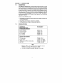
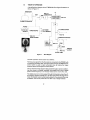
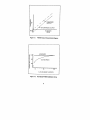
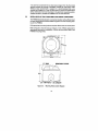
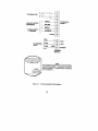
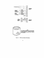
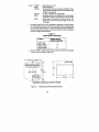
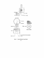
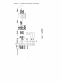
1
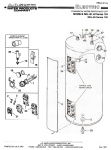
@a FTBSOO Series
Q
a Low
Flowrate Meters
(i%%i OPerator’s Manual
ka OMEGKj
Am D.aaw.4 Taek,.l.#hm
c..pmmy
Servicing USA and Canada: Call OMEGA To
USA
Canada
One Omega Drive, Box 4047
976 Bergar
il Free
Stamford, CT 06907.0047
Lava1 (Quebec) H7L 5Al
Telephone: (203) 359.1660
Telephone: (514) 856-6928
FAX: (203) 359-7700
FAX: (514) 856-6886
Sales Service: l-800-826-6342 / 1-800-TC-OMEGA-‘M
Customer Service: l-800-622-2378 / l-80%622~BESP
Engineering Service: l-800-872-9436 / I-800-USA-WHENSM
TELEX: 996404 EASYLINK: 62968934 CABLE: OMEGA
Servicing Europe: United Kingdom Sales and Distribution Center
25 Swannington Road, Broughton A&y, Leicestershire
LE9 6TU, England
Telephone: 44 (1455) 285520 FAX: 44 (1455) 283912
The OMEGA Co m p l ete M easure m ent and
Contro l Handbooks
& Encyc l oped i as
1c Temperature
V Data Acquisition Systems
V Pressure, Strain & Force
V Flow and Level
W pH andconductivity
V Electric Heaters
ti Environmental Monitoring
and Control
Call for Your FREE Handbook Request Form Today: (203) 359-RUSH
DFMOSSSFVRIBA
TABLE OF CONTENTS
FTB500 SERIES FLOWMETERS
PAGE
SECTION
SECTION 1
1.1
I.2
I.3
1.3.1
1.3.2
1.3.3
INTRODUCTION . . . . . . . . . . . . . . . . . . . . . . . . . .
Description .....................
Available Models .................
Theory of Operation ...............
Performance Characteristics .........
Viscosity Effects .................
Viscosity Calibration and UVC Curves ...
.
.
.
. .
. . .
. .
.I
.
.
.
.
.
.
.
SECTION 2 INSTALLATION ........ , ................. 6
2.1
2.2
2.3
2.4
2.5
Unpacking .................................
Operation ..................................
.
General ..................................
Installation Wiring Layout for Interconnections .........
Installation of the FTB500 Mini Flow Signal Conditioner ...
SECTION 3 CALIBRATION
3.1
3.2
3.3
3.4
3.4.1
3.4.2
4.1
4.2
7
. 7
. 8
.9
. . . . . . . . . , . . . . . . . . . . . . . . . . 2.I
Introduction .......................
Calibration Procedure .................
To Confirm FTBSOO Signal Conditioner Offset
Calibration of FTB500 Analog Output ......
.
Setup ...........................
Equations .........................
SECTION 4 MAINTENANCE
. 6
.
.
.
.
.
.
. . . .
. . .
. . .
. . .
I2
12
I3
I3
13
I3
. . . . .
. . . . . . . . . . . . . . . . . . . . . . . . . 5.I
Introduction . . . . . . . . . . . . . . . . , . . . . . .
Servicing and Preventative Maintenance of the FTBSOO
Flowmeter (Ball Bearing Design)
............
15
I5
SECTION 5 TROUBLESHOOTING AND MAINTENANCE a . . . . .8.I
SECTION 6
RECOMMENDED SPARE PARTS LIST . . . . . . . . . . 2
.0
SECTION 7 ACCESSORIES
..............,..........2
.0
SECTION 8 SPECIFICATIONS . . . . . . . . . . . . . . . . . . . . . . . .
.21
SECTION 1 INTRODUCTION
1.1
DESCRIPTION
The OMEGA@ FTB500 Series Low Flowmeters offer extremely accurate
low flow measurement of liquids and gases. They utilize a pelton wheel-like
rotor whose motion is converted into a pulse output proportional to flow
by a pickup coil. They come with an integral signal conditioner, powered
by either 15-35 VDC or 115 VAC (optional) to provide amplified frequency
and analog output. The signal conditioner corrects for the inherent zero offset of the flowmeter pulse output. It is mounted in a NEMA 4X, explosion
proof enclosure (Adalet XJS DO) rated for class I, groups C and D, and class
II, groups E, F and G.
Features of the FTB500 include:
1. Integral signal conditioner which provides K-factor offset correction for
the mini-flowmeters.
2. Versatile AC and DC power versions are available.
3. Configurable pulse voltage or analog output options.
1.2
AVAILABLE MODELS
DESCRIPTION
(LINEAR FLOW RANGE)
STANDARD PART NUMBERS
0.02 to 0.15 GPM
0.025 to 0.25 GPM
FTB501-( “CK)
FTB502-( “CK)
0.05 to 0.5 GPM
0.1 to 1.0 GPM
FTB503-( “CK)
FTB504-( ‘CK)
0.2 to 2.0 GPM
FTB505-(“CK)
PART NUMBER*
OPTIONAL PART NUMBERS
TTL Pulse output
FTB50_X-(*CK)-P
0-5VDC output
FTB50_X-t”CKb5VDC
115VAC signal conditioner power supply
FTB5O_X-(*CK)-115VAC
5000 PSIG
FTB50_X-t*CK)-5KP
NOTE
* Replace (“CK) in part number with the viscosity (in cen-
tistokesl of your liquid. The maximum is 25CK.
X 1 for 501, 2 for 502, 3 for 503,4 for 504, or 5 for 505.
1
1.3
THEORY OF OPERATION
A simplified block diagram of the FTB500 Mini Flow Signal Conditioner is
shown in Figure 1-I.
SENSITIVITY
+v
FTBBOO SIGNAL pcA_,,B
CONDITIONER
TURBINE FLOWMETER=
MAIN CHASSIS
CAPACITOR COUPLED
FREQ. TO
CONVERTER
ANALOG
OUTPUT
OUTPUT AMP.
Figure l-l.
Block Diagram
The basic operation of the system is as follows:
The frequency signal from the flowmeter is connected to the FTB500 with
a twisted pair shielded cable. The signal enters through the SENSITIVITY
control which is used to reject unwanted noise by raising the trigger
threshold above the background noise present.
The low level flowmeter signal is then passed through a special conditioning chain where it is filtered, amplified, and shaped into a train of digital
pulses whose frequency is non-linearly related to the volume flow rate.
The digital pulse train is then passed through the linearizer where the offset frequency signal is injected into it. For flow rates within the range of the
meter, the linearizer output will be linearly related to the volumetric flow rate
In addition, this circuitry drives the
‘low flow ’ out of range indicator.
2
The signal entering the frequency to analog converter is passed through a
combination of divide by N and DIP switch matrix. The output is chosen
whose pulse rate is between 75 and 150 Hz at the maximum flow rate to
be measured. This scaled pulse rate is fed into a precision monostable circuit. The output of the monostable is then filtered into an analog voltage
that is proportional to flow.
The output amplifier will take this voltage and perform either a voltage to
voltage amplifier or voltage to current amplifier.
Finally, the output is divided by 8 to reduce irregular pulse spacing. Then,
the pulse train enters a buffer and an attenuator simultaneously. The buffer output produces a square wave pulse which can be used as a CMOS/lTL
compatible output. The attenuator produces a capacitor coupled AC output which is suitable for driving other signal conditioners, indicators, or controllers which require an AC signal input.
The output frequency from the FTB500 Series Turbine Meter versus flow
is essentially a straight line of frequency as a function of flowrate which
does not pass through zero. left uncorrected, this will result in a K-factor
which varies with flow rate.
The FTBSOO integral signal conditioner will compensate for the frequency offset characteristics of the flowmeter, by using the method of offset
frequency injection. Offset frequency injection is implemented electronically
by adding a signal equal to the offset frequency required to linearize the output of the flowmeter. This effectively shifts the output characteristic to that
of the desired ideal. A low-flow cutout feature is provided where the offset signal is inhibited during no flow to prevent false outputs from being
generated.
The FTB500 Series Turbine Meter is a family of low flow rate measurement
devices based on a pelton wheel-like rotor. The measured fluid is directed
tangentially through a velocity nozzle against the pelton rotor causing it to
rotate The motion of the rotor is sensed by the pickup coil and converted
to a pulsing output signal where the frequency is related to the flowrate, and
the accumulated pulses are related to the total volume passing through the
flowmeter.
1.3.1
Performance Characteristics
The basic performance characteristics of the FTBSOO flowmeter are shown
in Figures l-2 and 1-3. The FTB500 Series of meters establish a linear
response after an initial offset correction when operating at a constant
viscosity.
3
lL
/
UN LINEARIZED OUTPUT
FLOW RATE
(GPM)
Figure 1-2.
FTBSOO Output Characterlstlcs Diagram
LINEARIZED
8
5
90
!
7 .80
f
u 1.00
I_7
UNLINEARIZED
10 50 100
% OF MAX IMUM
FLOWRATE
Figure 1-3.
Normalized FTBIOO Calibration Curve
4
Over the linear flow range, the input/output characteristics takes the form of:
Equation 1
Frequency = C, x Flowrate-C,
The FTB500 Series Turbine Meter requires the use of a linearization conditioner available in all OMEGA instrumentation. Accuracies of *l% of
reading are typical after initial correction for offset. Better accuracies approaching *2% are possible using smart transmitters which can store the
entire characteristics of the FTB500 Series Turbine Meter.
The K-Factor is the number of pulses per unit volume produced by the
flowmeter under a given set of conditions. Repeatability is a measure of the
stability of the output under a given set of flowing conditions. The
repeatability is defined as the allowable percentage deviation from the
stated K-Factor.
The pressure drop characteristics are given based on water at a viscosity
of 1 Cpse and a specific gravity of 1.00. For other fluid
’s, the following equation may be used to estimate the pressure drop across the
FTB500 Series
Turbine Meter given the pressure drop on water at the maximum flowrate
and the fluids viscosity and density.
PSID = (Cpsel” x (SpGr)” x PSID H,O
where:
Cpse is viscosity in centipoise
SpGr is the specific gravity
PSID H,O is the pressure drop from Figure l-4
Figure 14.
Gross Pressure Drop Characteristic Curve on Water
5
1.3.2 Viscosity Effects
An ideal flowmeter may be defined as one in which the output is solely a
function of the fluid flow being measured. Real flowmeters display
dependencies on secondary fluid properties, such as viscosity temperature,
and/or pressure. These effects tend to obscure or degrade the precision of
the flow measurement.
In very few flowmeter designs, the viscosity dependency is well understood
and given suitable documentation, may be compensated for. The OMEGA
instruments are among this select group.
In selecting an FTB500 Series Flowmeter for operation on a viscous fluid,
it is generally preferable to size the flowmeter so it will be operating in the
higher portion of its range to minimize viscosity effects in the measurement.
Some loss in flow turndown range may be expected.
1.3.3
Viscosity Calibration and UVC Curves
In some flowmeter applications the viscosity is held nearly constant owing
to regulated conditions of temperature and fluid consistency. For such applications it is only necessary to document the flowmeter
’s performance
at the expected operating viscosity. For such fixed viscosity applications
the standard specifications usually apply.
The FTB500 Series Turbine Meter may be used over wide viscosity ranges,
since the flowmeter has a unique, documented, Universal Viscosity Curve
(abbreviated UVC) which is accurate to *l% of reading.
In some applications, the fluid viscosity is a known function of temperature
A PC could be used to eliminate the otherwise adverse viscosity effect on
the flow measurement.
SECTION 2 INSTALLATION
2.1
UNPACKING
Remove the Packing list and verify that all equipment has been received.
If there are any questions about the shipment, please call the OMEGA
Customer Service.
Upon receipt of shipment, inspect the container and equipment for any
signs of damage. Take particular note of any evidence of rough handling in
transit. Immediately report any damage to the shipping agent.
NOTE
The carrier will not honor any claims unless all shipping material
is saved for their examination. After examining and removing contents, save packing material and carton in the event reshipment
is necessary.
2.2
OPERATION
Perform any purging of piping with spool piece in place. Once completed,
install the flowmeter and connect cabling to pickup coil.
With the FTB500 Mini Flow Signal Conditioner properly installed and
calibrated, verify the following performance.
With the power ON and no flow through the flowmeter, there should be no
pulse output from the unit. To verify this, connect either a digital Frequency Counter or an AC voltmeter.
If using a Digital Frequency Counter, the display should display zero. If some
other constant or varying indication occurs, noise may be present.
Slowly turn the SENSITIVITY threshold control counter-clockwise until indication stops.
NOTE
Turning the sensitivity control FULLY counter-clockwise will
render the outputs inoperative. Turn potentiometer clockwise to
return to normal operation.
If using an AC voltmeter, the meter should be at zera If noise is present, the
voltmeter will deflect and swing from 0 to 2.5V.
Slowly turn the SENSITIVITY threshold control counter-clockwise until indication stops.
2.3
GENERAL
Proper application of the turbine flowmeter requires a suitable piping installation in order to achieve accurate and reliable operation. Refer to Figure 2-l.
BYPASS RUN
I
FS
t
TFM
METER RUN Vl, V2 = BLOCKING VALVE
V3 = BYPASS VALVE
S = STRAINER
FS = FLOW STRAIGHTENER
TFM = TURBINE FLOWMETER
Figure 2-I.
Typical Turbine Meter Installation
7
v2
The piping configuration immediately preceeding and following the
flowmeter is termed the meter run.
METER RUN -In general, the meter run should be chosen to have the same
inner diameter as the meter bore. A minimum of IO pipe diameters of
straight pipe upstream and 5 pipe diameters downstream are required.
Where this optimum line configuration can not be implemented, it is advisable to install a flow straightener properly positioned upstream of the
flowmeter. Orientation is not a critical factor, however, horizontal is a preferred orientation.
RELATIVE-The performance of the turbine flowmeter is affected by fluid
swirl and non-uniform velocity profiles. The following recommendation will
reduce such flow irregularities.
It is advisable not to locate the meter run immediately downstream of
pumps, partially opened valves, bends or other similar piping configurations.
In addition, the area surrounding the flowmeter should be free of sources
of electrical noise such as motors, solinoids, transformers and power lines
which may be coupled to the pickoff device.
The metering section should not be subjected to excessive vibration or
shock. Such a condition may result in a mechanically induced output signal
from the pickoff device.
BYPASS RUN -A properly sized bypass run with suitable blocking valves
may be equipped where an interruption in fluid flow for turbine meters servicing can not be tolerated.
STRAINER-A strainer, filter and/or air eliminator is recommended to reduce
the potential of fouling or damage Recommended mesh size is at least 100
microns. Finer filters are preferred.
On initial startup of a line, it is advisable to install a spool piece purging the
line to eliminate damaging the flowmeter, due to flux, tape, solder, welds
or other contaminants carried along by the fluid stream.
2.4
INSTALLATION WIRING LAYOUT FOR INTERCONNECTIONS
In considering the interconnections between the flowmeter and the flow
measurement system some attention must be given to anticipated noise
sources and to the coupling of these noise sources to the interconnecting
wiring.
Noise signals may be coupled inductively or capacitively into the wiring between the flowmeter and the electronic measuring systems. In general, utilizing a shielded, twisted pair for the interconnection greatly reduces this
coupling. The shield should be grounded on one end of the cable only. In
general, grounding only on the electronic measuring system is best.
However, even with proper interconnecting cabling cross talk with other
signal lines or power lines may still occur and should be avoided. Physical
isolation in the manner in which the wiring is run reduces the chance of
potential problems.
B
It is common to transmit the low level output signal from the flowmeter
several hundred feet through a shielded, twisted pair instrument cable.
Where a noisy environment is suspect, it is recommended that a preamplifier be installed on or near the flowmeter to assure the preservation
of flow information from the flowmeter to the electronic measuring system.
Suitable accessory models are available from the manufacturer.
2.5
INSTALLATION OF THE FTB500 MINI FLOW SIGNAL CONDITIONER
The FTB500 should be placed in a convenient location with sufficient room
for easy opening of the enclosure Refer to Figure 2-2 for the mounting drawing for the FTB500.
Drill appropriate mounting holes as required. Mount the unit to the panel.
Refer to Figure 2-3 for DC hookup or Figure 2-4 for 115VAC (optional) for
appropriate terminals for installation. Connect the flowmeter cable to the
FTB500 including shield.
“0” RING
a--+------_,
-
REMOVABLE COVER
/
Tl=t.aJ
35/4” NPT FOR H ” I.D. CONDUIT
Figure 2-2.
Mounting Holes Location Diagram
9
To
-- 7x
A I -\I 1
PICKUPCOIL
:i
I 1
’ :,_ B .- --’ :,
+
ANALOG OUTPUT
(STANDARD)
1
PULSE OUTPUT
1-P OPTION)
0
Lo
SIGNAL
-
RETURN
+
SIGNAL
_
0
COMMON
F(TEBT)
@
TERMINAL
BLOCK 1
0
@
0
@
-
DC VOLTAGE
INPUT
TERMINAL
BLOCK 2
1234567
8
Figure 2-3.
NOTE
THE FTB500 IS EQUlPPED WITH AN INTEGRAL
CALIBRATION SIGNAL. TO INJECT THIS TEST
SIGNAL, INSTALL A JUMPER FROM TERMINAL
8 TO TERMINAL 1.
DC Input Installation Wiring Diagram
10
Xl PICKUP COIL
Ayy==+--~
TERMINAL
BLOCK 1
F(TEST)
@
u
IIBVAC
(NEUTRALS
50160 Hz E
INPUT
TERMINAL
BLOCK 2
NOTE
THE FTB500 IS EQUIPPED WITH AN INTEGRAL
CALIBRE \TlON SIGNAL. TO INJECT THIS TEST
SIGNAL, INSTALL A JUMPER FROM TERMINAL
8 TO TERMINAL 1.
Figure 24.
115VAC Input Installation Wiring Diagram
11
Connect the line power and ground to appropriate terminals. The line power
should be an ‘instrument grade ’ line whose various loads do not contain
solenoids, valves or other similar transient producing load which might
adversely affect the operation of the system.
Connect the cabling to the pulse output and to the inputs of the final
measurement system. Observe same precautions listed for interconnecting
cabling.
SECTION 3 CALIBRATION
3.1
INTRODUCTION
In general, all FTB500 flowmeter systems supplied by OMEGA Engineering,
Inc. have been factory calibrated at the time of purchase
All systems which were factory calibrated have a calibration card attached
prior to shipment. This card contains the flow rate, offset frequencyF(OSl
and low flow setpoint.
Field calibration is only required when a change has occurred. Such a
change may be due to repair, replacement or recalibration of the flowmeter.
3.2
CALIBRATION PROCEDURE
Before calibrating the FTB500 flowmeter, analog outputs, be sure the
response time adjustment potentiometer is turned fully clockwise for
fastest response time (0.5 seconds nominal). This potentiometer is found
inside the signal conditioner, inside the rectangular case, on the top printed
circuit board, just beneath terminal I. Slowest response time, with potentiometer fully counter-clockwise, is 2 seconds. Increasing the response time
can act to reduce “jitter” in the analog output.
Begin by determining the offset frequency of the mini flowmeter. This is supplied on the calibration card [F(OSl].
The mini flow signal conditioner may be calibrated with the internal TEST
frequency used in conjunction with a frequency counter.
The TEST switch, when jumpered to the input terminal (connecting Terminal
8 to Terminal 1, refer to Figure 2-3 or 2-41, injects an internally generated
frequency. When using this feature, F (TEST) is equal to 120 Hz.
F(OUT) = 1.8
where:
[F(TEST) + F(OS)l
FfOUTl is the output frequency of the linearizer
FfTEST) is the test frequency
FfOSl is the offset frequency
12
3.3
l7I CONFIRM FTBSOO SIGNAL CONDITIONER OFFSET
1. Connect frequency counter to the offset frequency test point of the unit.
2. Inject the TEST frequency and observe that the frequency equals 10
x F(OS).
For analog, go to Section 3.4.
For pulse, continue to step 3.
3. Connect frequency counter to the output of the unit and with an injected TEST frequency, verify that the output frequency equals
F(OUT)
in the equation stated above.
3.4
CALIBRATION OF FTBBOO ANALOG OUTPUT
3.4.1 Set Up
The signal conditioner may be calibrated with an internal “TEST” frequency
or an external oscillator used in conjunction with a frequency counter.
METHOD 1
As stated before, the “TEST” frequency jumpered to the input (Terminal 8
tied to Terminal 11, injects an internally generated frequency into the unit.
When using this feature, F (TEST) is equal to 120 Hz and is used in the
following equation.
Alternate or external oscillator may be used to supply a test frequency. In
this method, the external oscillator is connected to the signal input terminals. The oscillator ’s output frequency is set to equal F (MAX) as indicated on the frequency counter. For this approach, use F (MAX) in the
following equations for F (TEST).
Regardless of the method used, begin by calculating the following set points
indicated by Equation I through Equation 3. Use the frequency F (TEST)
depending on calibration method chosen above
3.4.2 Equations
Equation
1
F(MAX) = K FACTOR x R (MAX) _ F(GS)
60
Equation 2
Set (ZERO) = SET TO NO FLOW CONDITION
i.e., 4mA, 5mA, or OV
Equation 3
Set (SPAN) = [F (TEST) + F (OS11 x SPAN + ZERO
[F(MAXl + F (OS)1
13
where: F(TEST)
F(OSl
F(MAX)
K Factor
SPAN
ZERO
= test frequency used
= offset frequency
= the flowmeter output frequency at R(MAXl when
at the reference condition at which the relation with
F(MAX) was defined.
= in units of readout, ifi, PULSE/GAL
= varying component of analog output. For example,
16 mA for 4 to 20 mA output, 5V for 0 to 5V output
= fixed offset component of analog output. For
example, 4 mA for 4 to 20 mA output, OV for 0 to
5v output.
1. The Range Adjustment is accomplished by selecting a switch position
on a DIP switch located on the PCA-112 printed circuit card depending
on the model. Refer to Table 3-l to determine required switch position,
and select the switch position on the top printed circuit board adjacent
to the zero adjust potentiometer.
TABLE 3-1
RANGE SELECT SWITCHES
F (MAX)
300 to 600
600 to 1200
1200 to 2400
2400 to 4800
RANGE SELECT
SWITCH POSITION
3
4
5
6
2. Turn the “SPAN” potentiometer fully counter-clockwise until slippage
is felt or 25 turns. Refer to Figure 3-1.
* EQUIPPED FOR ANALOG OUTPUT OPTION
Figure 3-1.
Dimensions and Potentiometer locations
14
’
FOR CURRENT OUTPUT OPTION ONLY
3. Connect a digital milli-ammeter or equivalent, across the current output terminals.
4. Adjust “ZERO” potentiometer (refer to Figure 3-l) for desired “ZERO”
current (i.e., 4 mA).
5. Inject the test frequency while adjusting “SPAN” potentiometer (refer
to Figure 3-l) so the current equals to SET (SPAN).
6. Repeat steps 4 and 5 until no change is observed.
FOR VOLTAGE OUTPUT OPTION ONLY
7. Connect a digital voltmeter across the voltage output terminals.
8. Inject the test frequency while adjusting “SPAN” potentiometer so
voltage equals to SET (SPAN).
SECTION 4 MAINTENANCE
4.1
INTRODUCTION
OMEGA ’s FlowMeasurement_Systems are constructed to give a long service life. However, problems do occur from time to time and the following
points should be considered for preventative maintenance and repairs.
The bearing type used in the flowmeter was chosen to give compromise
between long life, chemical resistance, ease of maintenance and performance. A preventative maintenance schedule should be established to
determine the amount of wear which has occurred since last overhaul.
In case the flow measurement system malfunctions or becomes inoperative, refer to the Troubleshooting Guide in Section 5.
4.2
SERVICING AND PREVENTATIVE MAINTENANCE OF THE
FLOWMETER (BALL BEARING DESIGN)
FTBBOO
Preventative maintenance requires that the Mini Flowmeter under go a
general inspection. Refer to Figure 4-I and the following procedure to
remove the flowmeter internals from the housing. A clean work area is
required.
15
CORRECT
OR
IENTAT
ION
OF ROTOR
WHEN
ING
LOOK
DOWN FROM TOP
-8
OW
FL
FL OW -
DETA
IL OF ROTOR
WELO-
Figure
-1.4
Standard
llBear
Ba
ing ta
Cu
wayiagra
Dm
16
The FTB500 Flow m eter m ust be held in place by a vise.
Me ter orientation should be such that the threaded plug is facing upwards.
2. Using a screwdriver and turning counter clockwise, break the seal and
re move the plug.
3. Using tweezers or needle nose pliers, slowly pull the insert out, while
taking care not to da
m age the shaft or lose the thrust stop.
4. Remove
the rotor by using a pair of tweezers.
5. Remove
the shaft asse
m bly with s
m ooth needle nose pliers. Care
should be taken in not defor
m ing the shaft and loss of any parts.
6. Exa m ine the flo wme ter internals for signs of corrosion or fouling by
foreign
m aterials.
7. Exa m ine the shaft and bearings for signs of wear or corrosion on the
m ating surface.
m
8. If wear or corrosion is present in bearings, obtain new bearings fro
stock of the
m anufacturer.
9. Insert ball bearings in rotor.
10. Gu ide the rotor bearing asse
m bly onto the shaft.
Make sure to orient
the rotor so the cup side of the pelton whee l faces the IN side of the
housing. Refer to Figure 4-1 detail.
1.
NOTE
IF THE ROTOR
IS INSTALLED BACKWARDS
NOT G IVE YOU THE ACCURACY YOU REQU
DETA IL CLOSELY.
, THE METER
W ILL
IRE . REFER TO THE
Il. Install a new Viton “0” ring #77-545-018 or equivalent on the insert.
NOTE
“0” ring should be lightly lubricated with “0” ring lubrication
wh ich is silicone based.
12. P lace insert on the shaft.
W hen properly seated gently push the
insert back on the shaft.
13. Install and tighten the threaded plug. Tighten plug until snug. Do
not over tighten.
The flow m eter is ready for service
W hen installing the flow
m eter be sure
to orient the input and output correctly.
17
PCA-112
TO PICKUP COIL
ACIDC
POWER
SUPPLY
ANALOG
OUTPUT
ANALOG
OUPUT
COMMON
PULSE
OUTPUT
COMMON
FiTESTi
-
I
BLK
.
11 COIL-1
@
@
I-II-
WHT
GRN
0
Figure 5-1.
Internal Wiring
PCA-115
11
-1
FTBSOO
SIGNAL
CONDITIONER
TROUBLESHOOTING GUIDE (Cont ’d)
In case of an inoperable or malfunctioning system the following procedures
can be used to isolate the faulty wiring, printed circuit boards and/or alternate causes. The majority of repairs can be made in the field thereby reducing the time a unit is out of service
A recommended spare parts list is given in Section 6. The necessary
documentation is contained within this manual with the exception of the
calibration data sheet for the turbine flowmeter. This calibration is supplied
separately.
To test the FTB500, an internal 120 Hz test frequency has been provided.
Refer to Section 3.2, Calibration Procedure Failure conditions are listed and
the possible corrective actions are given to eliminate the observed problems.
TROUBLESHOUTING GU IDE
OBSERVED CONDITION
Unit repeatedly blows fuses.
Unit gives no pulse output
w ith flow present.
Unit gives pulse output with
no flow present
CORRECTIVE ACTION
1. Inspect terminal strip wiring for conformity to the installation instructions and for
acceptable workmanship
2. Verify correct fuse size.
3. Replace PCA-112.
4. Replace PCA-115.
5. Replace PCA-114.
NOTE
If unit continues to blow fuses it is
advisable to return it to the factory.
This defect is difficult to diagnose in
an assembled system.
1. Turn sensitivity (SENS) potentiometer
clockwise
2. Replace pickup coil and/or interconnecting wiring.
3. Replace PCA-114.
4. Replace PCA-115.
5. Replace PCA-112.
1. Noise pickup, turn sensitivity adjust
counter clockwise until correct zero flow
indication is obtained.
2. Replace pickup coil.
3. Replace PCA-115.
4. Replace PCA-114.
19
TROUBLESHOOTING GUIDE (Cont ’dl
OBSERVED CONDITION
Unit does not function
Analog output.
Analog output with no flow.
CORRECTIVE ACTION
I. PCA-115 has incorrect offset frequency
setting.
2. Replace PCA-115.
3. Flowmeter used below or above normal
range. Obtain correct flowmeter.
1. Replace PCA-112.
1. Turn sensitivity (SENS) potentiometer
slowly ccw.
NOTE
Fully CCW will make the unit inoperative.
2. Replace PCA-112.
SECTION 6
RECOMMENDED SPARE PARTS LIST
PART NUMBER
PCA-112
DESCRIRTION
POWER SUPPLY/ANALOG OUTPUT CARD
QTY
PCA-II4
SIGNAL CONDITIONER CARD
(MAGNETIC PICKUP COIL)
I
PCA-115
LINEARIZE AND FLOW DRIVE,
PLUG-IN CARD
I
‘/4 SLO BLO
FUSES, POWER SUPPLY
1 BOX
SECTION 7 ACCESSORIES
DESCRIPTION
% w MS flare to % n MNPT adaptor kit with
10” upstream and 5” downstream straight
SS tubing
20
PART NUMBER
FTB500-ADP
1
SECTION 8 SPECIFICATIONS
INPUT POWER OPTION:
15 to 35 VDC at 75 mA (standard)
115VAC, 50/60 Hz (optional)
INPUT
Input protected, RF and band pass
filtered, adjustable trigger level.
Input impedance-4OkQ
Trigger sensitivity-IOmV,,,(minimum)
10 Hz to 1000 Hz
Over voltage-120V,,, absolute
(maximum)
METHOD:
Frequency injection of offset frequency
with post scaling and low flow alarm
OFFSET FREQUENCY:
7 to 150 Hz
THERMAL STABILITY:
200 parts per million/°C
LOW FLOW ADJUSTMENT
I
20 to 200 Hz (based on comparison with
input flowmeter frequency)
LOW FLOW INDICATION:
None
ACCURACY:
+ 1% of reading for pulse
REPEATABILITY:
*0.25% of reading
MAX. PRESSURE DROP AT ICSTK:
IO PSID
MAX. PRESSURE:
1000 PSIG standard
5000 PSIG optional
FREQUENCY OUTPUT AT FULLSCALEFLOW bP OPTION, REFER TO
SECTION 1.2):
ANALOG OUTPUTS
CURRENT OUTPUT (STANDARD):
ACCURACY:
RANGE:
RESPONSE TIME:
125 Hz nominal
+0.05% of full scale,
+200 PPM/OC.
4 to 20mA into 375X max.
0.5 seconds for IO-go%.
Adjustable from 0.5 to 2 seconds.
Output suitable for driving grounded or
floating load types
VOLTAGE OUTPUT (OPTIONAL):
ACCURACY:
RANGE:
IMPEDANCE:
RESPONSE TIME:
*0.05% of full scale; *200 PPM/OC.
o-5v.
<IO9
0.5 seconds for IO-90%
21
SPECIFICATIONS (Cont ’d)
PULSE OUTPUTS (OPTIONAL):
STANDARD OPTION -TTUCMOS fanout
of IO TTL/CMOS loads. AC capacitively
coupled square wave.
OPTIONAL-Open collector -adjustable
V,,, transistor 2N6660. Maximum OFF
state voltage 60 VDC. Maximum ON current I.OA.
ENVIRONMENTAL
OPERATING AMBIENT TEMPERATURE:
FLUID TEMPERATURE RANGE:
STORAGE TEMPERATURE:
-4O to 176OF
-450° to +450°F
-65” to 150°C
MATERIALS OF CONSTRUCTION
HOUSING:
BALL BEARINGS:
ROTOR:
SEALS:
CONNECTIONS:
316 Stainless Steel
44oc
17-4 PH
Viton
% n 37O flare per MS-33656-8
% II MNPT adaptor kit optional
CONTROLS AND ADJUSTMENTS
FUSE:
A circuit protection device located internally. Check main schematic for proper
size and type.
SENS:
A single control used to set the threshold
sensitivity level above the ambient noise
pickup.
OFFSET FREQUENCY:
An internal 20 turn adjustment on the
PCA-II5 printed circuit card used to adjust the equivalent offset frequency of the
FTB500, 7 to 150 Hz.
LOW FLOW ADJUST:
An internal adjustment on the PCA-115
printed circuit card which is factory set to
turn off the offset frequency oscillator at
no flow.
RANGE:
A dual-in-line (DIP) switch located on a
PCA-112 board which is used to program
the module to accept an input frequency
range.
ZERO:
A multiple turn adjustment potentiometer
which is used to set the current/voltage
output signal with no flow to the desired
“zero” value (i.e., 4 mA or 100 mA).
SPECIFICATIONS (Cont ’d)
SPAN:
A multiple turn adjustment potentiometer
which is used to set the current/voltage
output signal to the desired span corresponding to mA equivalent flow range
(i.e., 4 to 20 mA or 0 to 1OV corresponding to O-100GPM).
RESPONSE:
A multiple turn adjustment potentiometer
which is used to dampen the response at
the analog output.
SCALING FACTOR:
A dual-in-line (DIP) switch located on the
PCA-112 board which is used to select the
desired pulse output scaling factor.
23
WARRANTY
@zz
OMEGA warrants this unit to be free of defects in materials and workmanship and to give
satisfactory service for a period of 13 months from date of purchase. OMEGA Warranty
adds an additional one (1) month grace period to the normal one (11 year product
warranty to cover handling and shipping time. This ensures that OMEGA ’scustomers
receive maximum coverage on each product. If the unit should malfunction, it must be
returned to the factory for evaluation. OMEGA ’s Customer Service Department will issue
an Authorized Return (AR) number immediately upon phone or written request Upon
examination by OMEGA, if the unit is found to be defective it will be repaired or replaced at
no charge. However, this WARRANTY is VOID if the unit shows evidence of having been
tampered with or shows evidence of being damaged as a result of excessive corrosion; or
current, heat, moisture or vibration; improper specification; misapplication; misuse or
other operating conditions outside of OMEGA
’s control. Components which wear or which
are damaged by misuse are not warranted. These include contact points, fuses, and triacs.
OMEGA is glad to offer suggestions on the use of its various products.
Nevertheless, OMEGA only warrants that the parts manufactured by it will be as
specified and free of defects.
OMEGA MAKES NO OTHER WARRANTIES OR REPRESENTATIONS OF ANY KIND
WHATSOEVER, EXPRESSED OR IMPLIED, EXCEPT THAT OF TITLE AND ALL
IMPLIED WARRANTIES INCLUDING ANY WARRANTY OF MERCHANTABILITY
AND FlTNESS FOR A PARTICULAR PURPOSE ARE HEREBY DISCLAIMED.
LIMITATION OF LIABILITY: The remedies of purchaser set forth herein are
exclusive and the total liability of OMEGA with respect to this order, whether
based on contract, warranty, negligence, indemnification, strict liability or
otherwise, shall not exceed the purchase price of the component upon which
liability is based. In no event shall OMEGA be liable for consequential, incidental
or special damages.
Every precaution for accuracy has been taken in the preparation of this manual; however,
OMEGA ENGINEERING, INC. neither assumes responsibility for any omissions or errors
that may appear nor assumes liability for any damages that result from the use of the
products in accordance with the information contained in the manual.
SPECIAL CONDITION: Should this equipment be used in or with any nuclear installation or
activity, purchaser will indemnify OMEGA and hold OMEGA harmless from any liability or
damage whatsoever arising out of the use of the equipment in such a manner.
~~~?~~~~~,$~~~~~~~~~~~.~~~
RETURN REQUESTS / lNQUlR[ES ~$%~~~y~~~~~%
Direct all warranty and repair requests/inquiries to the OMEGA ENGINEERING Customer
Service Department. BEFORE RETURNING ANY PRODUCT(S) TO OMEGA, PURCHASER
MUST OBTAIN AN AUTHORIZED RETURN (AR) NUMBER FROM OMEGA ’S CUSTOMER
SERVICE DEPARTMENT (IN ORDER TO AVOID PROCESSING DELAYS). The assigned AR
number should then be marked on the outside of the return package and on any correspondence.
FOR WARRANTY RETURNS, please have
the following information available
BEFORE contacting OMEGA:
FOR NON-WARRANN REPAIRS OR CALI_
BRATIDN, consult OMEGA for current
repair/calibration charges. Have the following
1. P.O. number under which the product
was PURCHASED,
2. Model and serial number of the product
under warranty, and
3. Repair instructions and/or specific
problems relative to the product.
information available BEFORE contacting
OMEGA:
1. P.O. number to cover the COST of the
repair/ calibration,
2. Model and serial number of product, and
3. Repair instructions and/or specific
problems relative to the product.
OMEGA ’s policy is to make running changes, not model changes, whenever an improvement is possible. This affords our customers rhe latest in technology and engineering.
OMEGA is a registered trademark of OMEGA ENGINEERING, INC.
0 Copyright 1995 OMEGA ENGINEERING, INC. All rights reserved. This documentation
may not be copied, photocopied, reproduced, translated, or reduced to any electronic
medium or machine-readable form, in whole or in part, without prior written consent of
OMEGA ENGINEERING, INC.
Where Do I Find Everything I Need for
Process Measurement and Control?
OMEGA...Of Course!
TEMPERATURE
m Thermocouple, RTD
& Thermistor Probes, Connectors, Panels
m Wire: Thermocouple, RTD & Thermistor
@’ Calibrators & Ice Point References
m Recorders, Controllers
& Process Monitors
B Infrared Pyrometers
& Assemblies
PRESSURE/STRAIN FORCE
b8 Transducers & Strain Gages
B Load Cells & Pressure Gauges
m Displacement Transducers
k? Instrumentation & Accessories
FLOW / LEVEL
@ Rotameters, Gas Mass Flowmeters
@’Air Velocity Indicators
& Flow Computers
@’ Turbine/Paddlewheel Systems
@’Totalizers & Batch Controllers
H/CONDUCTIVITY
g pH Electrodes, Testers & Accessories
m Benchtop/Laboratory Meters
m Controllers, Calibrators, Simulators
& Pumps
m Industrial pH & Conductivity Equipment
DATA ACQUISITION
m Data Acquisition and Engineering Software
m Communications-Based Acquisition Systems
i$? Plug-in Cards for Apple, IBM
Bs Compatibles
ij? Datalogging Systems
m Recorders, Printers
& Plotters
HEATERS
bd’Heating Cable
k? Cartridge & Strip Heaters
m Immersion & Band Heaters
k? Flexible Heaters
m Laboratory Heaters
ENV IRONMENTAL MON
D Metering & Control Instrumentation
ITORING AND CONTROL
Refractometers
iZ!’ Pumps & Tubing
m Air, Soil &Water Monitors
m Industrial Water & Wastewater Treatment
k!’ pH, Conductivity & Dissolved Oxygen Instruments
b?
MO968 /0992