1
Te c h n i c a l R e f e re n c e
020-100224-10
M Series
Serial API Commands
NOTICES
COPYRIGHT AND TRADEMARKS
Copyright ©2015 Christie Digital Systems USA Inc. All rights reserved.
All brand names and product names are trademarks, registered trademarks or trade names of their respective holders.
GENERAL
Every effort has been made to ensure accuracy, however in some cases changes in the products or availability could occur which may not be reflected in
this document. Christie reserves the right to make changes to specifications at any time without notice. Performance specifications are typical, but may
vary depending on conditions beyond Christie's control such as maintenance of the product in proper working conditions. Performance specifications
are based on information available at the time of printing. Christie makes no warranty of any kind with regard to this material, including, but not limited
to, implied warranties of fitness for a particular purpose. Christie will not be liable for errors contained herein or for incidental or consequential damages
in connection with the performance or use of this material. Canadian manufacturing facility is ISO 9001 and 14001 certified.
WARRANTY
Products are warranted under Christie’s standard limited warranty, the complete details of which are available by contacting your Christie dealer or
Christie. In addition to the other limitations that may be specified in Christie’s standard limited warranty and, to the extent relevant or applicable to your
product, the warranty does not cover:
a. Problems or damage occurring during shipment, in either direction.
b. Projector lamps (See Christie’s separate lamp program policy).
c. Problems or damage caused by use of a projector lamp beyond the recommended lamp life, or use of a lamp other than a Christie lamp supplied
by Christie or an authorized distributor of Christie lamps.
d. Problems or damage caused by combination of a product with non-Christie equipment, such as distribution systems, cameras, DVD players, etc., or
use of a product with any non-Christie interface device.
e. Problems or damage caused by the use of any lamp, replacement part or component purchased or obtained from an unauthorized distributor of
Christie lamps, replacement parts or components including, without limitation, any distributor offering Christie lamps, replacement parts or
components through the internet (confirmation of authorized distributors may be obtained from Christie).
f. Problems or damage caused by misuse, improper power source, accident, fire, flood, lightening, earthquake or other natural disaster.
g. Problems or damage caused by improper installation/alignment, or by equipment modification, if by other than Christie service personnel or a
Christie authorized repair service provider.
h. Problems or damage caused by use of a product on a motion platform or other movable device where such product has not been designed,
modified or approved by Christie for such use.
i. Problems or damage caused by use of a projector in the presence of an oil-based fog machine or laser-based lighting that is unrelated to the
projector.
j. For LCD projectors, the warranty period specified in the warranty applies only where the LCD projector is in “normal use” which means the LCD
projector is not used more than 8 hours a day, 5 days a week.
k. Except where the product is designed for outdoor use, problems or damage caused by use of the product outdoors unless such product is
protected from precipitation or other adverse weather or environmental conditions and the ambient temperature is within the recommended
ambient temperature set forth in the specifications for such product.
l. Image retention on LCD flat panels.
m.Defects caused by normal wear and tear or otherwise due to normal aging of a product.
The warranty does not apply to any product where the serial number has been removed or obliterated. The warranty also does not apply to any product
sold by a reseller to an end user outside of the country where the reseller is located unless (i) Christie has an office in the country where the end user is
located or (ii) the required international warranty fee has been paid.
The warranty does not obligate Christie to provide any on site warranty service at the product site location.
PREVENTATIVE MAINTENANCE
Preventative maintenance is an important part of the continued and proper operation of your product. Please see the Maintenance section for specific
maintenance items as they relate to your product. Failure to perform maintenance as required, and in accordance with the maintenance schedule
specified by Christie, will void the warranty.
REGULATORY
The product has been tested and found to comply with the limits for a Class A digital device, pursuant to Part 15 of the FCC Rules. These limits are
designed to provide reasonable protection against harmful interference when the product is operated in a commercial environment. The product
generates, uses, and can radiate radio frequency energy and, if not installed and used in accordance with the instruction manual, may cause harmful
interference to radio communications. Operation of the product in a residential area is likely to cause harmful interference in which case the user will be
required to correct the interference at the user’s own expense.
CAN ICES-3 (A) / NMB-3 (A)
이 기기는 업무용 (A 급 ) 으로 전자파적합등록을 한 기기이오니 판매자 또는 사용자는 이점을 주의하시기 바라며 , 가정 외의 지역에서 사용하는 것을
목적으로 합니다 .
Environmental
means that electrical and
The product is designed and manufactured with high-quality materials and components that can be recycled and reused. This symbol
electronic equipment, at their end-of-life, should be disposed of separately from regular waste. Please dispose of the product appropriately and according to local
regulations. In the European Union, there are separate collection systems for used electrical and electronic products. Please help us to conserve the environment
we live in!
Content
Introduction . . . . . . . . . . . . . . . . . . . . . . . . . . . . . . . . . . . . . . . . . . . . . . . . . 9
Connection and use
. . . . . . . . . . . . . . . . . . . . . . . . . . . . . . . . . . . . . . . . . . . . . .9
Understanding message format
. . . . . . . . . . . . . . . . . . . . . . . . . . . . . . . . . . . . . .9
Message formats . . . . . . . . . . . . . . . . . . . . . . . . . . . . . . . . . . . . . . . . . . . . . 10
Basic message structure . . . . . . . . . . . . . . . . . . . . . . . . . . . . . . . . . . . . . . . . 10
Special characters for text . . . . . . . . . . . . . . . . . . . . . . . . . . . . . . . . . . . . . . . 12
Sample messages and their meaning
. . . . . . . . . . . . . . . . . . . . . . . . . . . . . . . 12
What is sent in a message
. . . . . . . . . . . . . . . . . . . . . . . . . . . . . . . . . . . . . . 13
Maximizing message integrity
. . . . . . . . . . . . . . . . . . . . . . . . . . . . . . . . . . . . . . 13
Message errors
. . . . . . . . . . . . . . . . . . . . . . . . . . . . . . . . . . . . . . . . . . . . . . 14
Descriptive error . . . . . . . . . . . . . . . . . . . . . . . . . . . . . . . . . . . . . . . . . . . . . 15
Accessing specific channels or inputs
Flow control
. . . . . . . . . . . . . . . . . . . . . . . . . . . . . . . 15
. . . . . . . . . . . . . . . . . . . . . . . . . . . . . . . . . . . . . . . . . . . . . . . . 16
Network operation . . . . . . . . . . . . . . . . . . . . . . . . . . . . . . . . . . . . . . . . . . . . 16
Description of control types . . . . . . . . . . . . . . . . . . . . . . . . . . . . . . . . . . . . . . . . 17
Subclasses
. . . . . . . . . . . . . . . . . . . . . . . . . . . . . . . . . . . . . . . . . . . . . . . . . 17
Control groups . . . . . . . . . . . . . . . . . . . . . . . . . . . . . . . . . . . . . . . . . . . . . . . 17
Access levels . . . . . . . . . . . . . . . . . . . . . . . . . . . . . . . . . . . . . . . . . . . . . . . . 18
M Series Serial API Commands . . . . . . . . . . . . . . . . . . . . . . . . . . . . . . . . . 19
ACE–Auto Color Enable . . . . . . . . . . . . . . . . . . . . . . . . . . . . . . . . . . . . . . . . . . . 19
ACO–Adaptive Contrast . . . . . . . . . . . . . . . . . . . . . . . . . . . . . . . . . . . . . . . . . . . 20
ACT–Active Window
. . . . . . . . . . . . . . . . . . . . . . . . . . . . . . . . . . . . . . . . . . . . . 20
ADR–Address . . . . . . . . . . . . . . . . . . . . . . . . . . . . . . . . . . . . . . . . . . . . . . . . . . 21
AGC–Automatic Gain Control . . . . . . . . . . . . . . . . . . . . . . . . . . . . . . . . . . . . . . . 22
AIC–Auto Input Cycling . . . . . . . . . . . . . . . . . . . . . . . . . . . . . . . . . . . . . . . . . . . 23
AIL–Auto Input Level
. . . . . . . . . . . . . . . . . . . . . . . . . . . . . . . . . . . . . . . . . . . . 23
ALT–Active Loop-Through . . . . . . . . . . . . . . . . . . . . . . . . . . . . . . . . . . . . . . . . . 24
APJ–Active Projector . . . . . . . . . . . . . . . . . . . . . . . . . . . . . . . . . . . . . . . . . . . . . 25
APW–Auto Power Up . . . . . . . . . . . . . . . . . . . . . . . . . . . . . . . . . . . . . . . . . . . . . 26
ARO–Aspect Ratio Overlay . . . . . . . . . . . . . . . . . . . . . . . . . . . . . . . . . . . . . . . . . 26
ASH–Auto Shutdown . . . . . . . . . . . . . . . . . . . . . . . . . . . . . . . . . . . . . . . . . . . . . 27
ASR–Auto Channel Select
. . . . . . . . . . . . . . . . . . . . . . . . . . . . . . . . . . . . . . . . . 28
ASU–Auto Setup . . . . . . . . . . . . . . . . . . . . . . . . . . . . . . . . . . . . . . . . . . . . . . . . 29
M Series Serial API Commands Technical Reference
020-100224-10 Rev. 1 (01-2015)
3
Content
BBL–Bottom Blanking . . . . . . . . . . . . . . . . . . . . . . . . . . . . . . . . . . . . . . . . . . . . 30
BDR–Baud Rate . . . . . . . . . . . . . . . . . . . . . . . . . . . . . . . . . . . . . . . . . . . . . . . . 31
BGC–Base Gamma Curve . . . . . . . . . . . . . . . . . . . . . . . . . . . . . . . . . . . . . . . . . . 32
BGF–Base Gamma Function . . . . . . . . . . . . . . . . . . . . . . . . . . . . . . . . . . . . . . . . 33
BGS–Base Gamma Slope . . . . . . . . . . . . . . . . . . . . . . . . . . . . . . . . . . . . . . . . . . 34
BKY–Broadcast Key Mode
. . . . . . . . . . . . . . . . . . . . . . . . . . . . . . . . . . . . . . . . . 35
BLB–Blue Black Level . . . . . . . . . . . . . . . . . . . . . . . . . . . . . . . . . . . . . . . . . . . . 35
BLD–Blue Drive . . . . . . . . . . . . . . . . . . . . . . . . . . . . . . . . . . . . . . . . . . . . . . . . 36
BOG–Blue Odd Pixel Gain
. . . . . . . . . . . . . . . . . . . . . . . . . . . . . . . . . . . . . . . . . 37
BOO–Blue Odd Pixel Offset
. . . . . . . . . . . . . . . . . . . . . . . . . . . . . . . . . . . . . . . . 38
BRT–Brightness . . . . . . . . . . . . . . . . . . . . . . . . . . . . . . . . . . . . . . . . . . . . . . . . 38
BRU–Brightness Uniformity . . . . . . . . . . . . . . . . . . . . . . . . . . . . . . . . . . . . . . . . 40
CCD–Output Color Default . . . . . . . . . . . . . . . . . . . . . . . . . . . . . . . . . . . . . . . . . 42
CCI–Interpolated Color . . . . . . . . . . . . . . . . . . . . . . . . . . . . . . . . . . . . . . . . . . . 43
CCS–Select Output Color . . . . . . . . . . . . . . . . . . . . . . . . . . . . . . . . . . . . . . . . . . 43
CHA–Channel . . . . . . . . . . . . . . . . . . . . . . . . . . . . . . . . . . . . . . . . . . . . . . . . . . 44
CLE–Color Enable . . . . . . . . . . . . . . . . . . . . . . . . . . . . . . . . . . . . . . . . . . . . . . . 46
CLP–Clamping . . . . . . . . . . . . . . . . . . . . . . . . . . . . . . . . . . . . . . . . . . . . . . . . . 46
CLR–Color . . . . . . . . . . . . . . . . . . . . . . . . . . . . . . . . . . . . . . . . . . . . . . . . . . . . 47
CON–Contrast . . . . . . . . . . . . . . . . . . . . . . . . . . . . . . . . . . . . . . . . . . . . . . . . . 48
CRM–Chroma/Luma Delay . . . . . . . . . . . . . . . . . . . . . . . . . . . . . . . . . . . . . . . . . 49
CSP–Color Space Selection
. . . . . . . . . . . . . . . . . . . . . . . . . . . . . . . . . . . . . . . . 50
DED–Dual DVI EDID Type Selection
. . . . . . . . . . . . . . . . . . . . . . . . . . . . . . . . . . 52
DEF–Factory Defaults . . . . . . . . . . . . . . . . . . . . . . . . . . . . . . . . . . . . . . . . . . . . 52
DEQ–DDIC Equalization Level . . . . . . . . . . . . . . . . . . . . . . . . . . . . . . . . . . . . . . . 53
DIM–Dynamic Iris Mode
. . . . . . . . . . . . . . . . . . . . . . . . . . . . . . . . . . . . . . . . . . 54
DIS–Dynamic Iris Settings . . . . . . . . . . . . . . . . . . . . . . . . . . . . . . . . . . . . . . . . . 54
DLG–Data Logging . . . . . . . . . . . . . . . . . . . . . . . . . . . . . . . . . . . . . . . . . . . . . . 55
DMX–DMX/ArtNet . . . . . . . . . . . . . . . . . . . . . . . . . . . . . . . . . . . . . . . . . . . . . . . 56
DRK–3D Dark Interval . . . . . . . . . . . . . . . . . . . . . . . . . . . . . . . . . . . . . . . . . . . . 58
DTL–Detail
. . . . . . . . . . . . . . . . . . . . . . . . . . . . . . . . . . . . . . . . . . . . . . . . . . . 59
DTO–Detail Overshoot . . . . . . . . . . . . . . . . . . . . . . . . . . . . . . . . . . . . . . . . . . . . 59
DTT–Detail Threshold . . . . . . . . . . . . . . . . . . . . . . . . . . . . . . . . . . . . . . . . . . . . 60
EBB–Black Level Blending . . . . . . . . . . . . . . . . . . . . . . . . . . . . . . . . . . . . . . . . . 61
EBL–Edge Blending
. . . . . . . . . . . . . . . . . . . . . . . . . . . . . . . . . . . . . . . . . . . . . 62
EME–Error Message Enable
. . . . . . . . . . . . . . . . . . . . . . . . . . . . . . . . . . . . . . . . 64
ESC–Edit Secondary Channel Setting
. . . . . . . . . . . . . . . . . . . . . . . . . . . . . . . . . 64
FAD–Fade Time . . . . . . . . . . . . . . . . . . . . . . . . . . . . . . . . . . . . . . . . . . . . . . . . 65
M Series Serial API Commands Technical Reference
020-100224-10 Rev. 1 (01-2015)
4
Content
FAS–Fan Assist Switch
. . . . . . . . . . . . . . . . . . . . . . . . . . . . . . . . . . . . . . . . . . . 65
FCS–Lens Focus Position Adjustment . . . . . . . . . . . . . . . . . . . . . . . . . . . . . . . . . . 66
FIL–Filter
. . . . . . . . . . . . . . . . . . . . . . . . . . . . . . . . . . . . . . . . . . . . . . . . . . . . 67
FLE–Frame Lock Enable . . . . . . . . . . . . . . . . . . . . . . . . . . . . . . . . . . . . . . . . . . . 68
FLW–Serial Flow Control . . . . . . . . . . . . . . . . . . . . . . . . . . . . . . . . . . . . . . . . . . 68
FMD–Film Mode Detect . . . . . . . . . . . . . . . . . . . . . . . . . . . . . . . . . . . . . . . . . . . 69
FRD–Frame Delay . . . . . . . . . . . . . . . . . . . . . . . . . . . . . . . . . . . . . . . . . . . . . . . 70
FRF–Free Run Frequency . . . . . . . . . . . . . . . . . . . . . . . . . . . . . . . . . . . . . . . . . . 70
FRZ–Image Freeze . . . . . . . . . . . . . . . . . . . . . . . . . . . . . . . . . . . . . . . . . . . . . . 71
FTB–Fade to Black . . . . . . . . . . . . . . . . . . . . . . . . . . . . . . . . . . . . . . . . . . . . . . 72
GAM–Gamma Correction . . . . . . . . . . . . . . . . . . . . . . . . . . . . . . . . . . . . . . . . . . 72
GIA–Analog BNC Grounded Input Selection . . . . . . . . . . . . . . . . . . . . . . . . . . . . . 73
GID–Video Decoder Grounded Input Selection . . . . . . . . . . . . . . . . . . . . . . . . . . . 74
GIO–General Purpose Input/Output . . . . . . . . . . . . . . . . . . . . . . . . . . . . . . . . . . . 74
GMS–VDIC Grouped-Inputs Mode . . . . . . . . . . . . . . . . . . . . . . . . . . . . . . . . . . . . 75
GNB–Green Black Level . . . . . . . . . . . . . . . . . . . . . . . . . . . . . . . . . . . . . . . . . . . 76
GND–Green Drive . . . . . . . . . . . . . . . . . . . . . . . . . . . . . . . . . . . . . . . . . . . . . . . 77
GOG–Green Odd Pixel Gain . . . . . . . . . . . . . . . . . . . . . . . . . . . . . . . . . . . . . . . . 78
GOO–Green Odd Pixel Offset . . . . . . . . . . . . . . . . . . . . . . . . . . . . . . . . . . . . . . . 79
HDC–DHDIC Dual-Link Configuration . . . . . . . . . . . . . . . . . . . . . . . . . . . . . . . . . . 79
HIS–Lamp History
. . . . . . . . . . . . . . . . . . . . . . . . . . . . . . . . . . . . . . . . . . . . . . 80
HLP–Serial Help . . . . . . . . . . . . . . . . . . . . . . . . . . . . . . . . . . . . . . . . . . . . . . . . 81
HLT–Projector Health (HLT) . . . . . . . . . . . . . . . . . . . . . . . . . . . . . . . . . . . . . . . . 82
HOR–Horizontal Position . . . . . . . . . . . . . . . . . . . . . . . . . . . . . . . . . . . . . . . . . . 83
ILS–Intelligent Lens System
. . . . . . . . . . . . . . . . . . . . . . . . . . . . . . . . . . . . . . . 83
ILV–ILS Settings Valid . . . . . . . . . . . . . . . . . . . . . . . . . . . . . . . . . . . . . . . . . . . . 84
INM–Channel In Menu . . . . . . . . . . . . . . . . . . . . . . . . . . . . . . . . . . . . . . . . . . . . 85
IRS–Dynamic Iris . . . . . . . . . . . . . . . . . . . . . . . . . . . . . . . . . . . . . . . . . . . . . . . 86
ITG–Test Pattern Grey
. . . . . . . . . . . . . . . . . . . . . . . . . . . . . . . . . . . . . . . . . . . 87
ITP–Internal Test Pattern
. . . . . . . . . . . . . . . . . . . . . . . . . . . . . . . . . . . . . . . . . 88
KEN–Keypad IR Sensor Disable
KEY–Key Mode Emulation
. . . . . . . . . . . . . . . . . . . . . . . . . . . . . . . . . . . . . 89
. . . . . . . . . . . . . . . . . . . . . . . . . . . . . . . . . . . . . . . . . 90
LBL–Left Blanking . . . . . . . . . . . . . . . . . . . . . . . . . . . . . . . . . . . . . . . . . . . . . . . 90
LCB–Lens System Calibration . . . . . . . . . . . . . . . . . . . . . . . . . . . . . . . . . . . . . . . 91
LCD–LCD Backlight . . . . . . . . . . . . . . . . . . . . . . . . . . . . . . . . . . . . . . . . . . . . . . 93
LDT–Level Detector
. . . . . . . . . . . . . . . . . . . . . . . . . . . . . . . . . . . . . . . . . . . . . 94
LDV–Level Detector Value . . . . . . . . . . . . . . . . . . . . . . . . . . . . . . . . . . . . . . . . . 94
LHO–Lens Horizontal Position Adjustment
M Series Serial API Commands Technical Reference
020-100224-10 Rev. 1 (01-2015)
. . . . . . . . . . . . . . . . . . . . . . . . . . . . . . 95
5
Content
LLC–LiteLoc Calibration . . . . . . . . . . . . . . . . . . . . . . . . . . . . . . . . . . . . . . . . . . . 96
LMV–Adjust Lens Position/Lens Move
. . . . . . . . . . . . . . . . . . . . . . . . . . . . . . . . . 96
LOC–Localization Language . . . . . . . . . . . . . . . . . . . . . . . . . . . . . . . . . . . . . . . . 98
LOP–Lamp Operation
. . . . . . . . . . . . . . . . . . . . . . . . . . . . . . . . . . . . . . . . . . . . 98
LOS–Loop Out Source Selection . . . . . . . . . . . . . . . . . . . . . . . . . . . . . . . . . . . . . 99
LPI–Lamp Intensity . . . . . . . . . . . . . . . . . . . . . . . . . . . . . . . . . . . . . . . . . . . . . 100
LPL–Lamp Life . . . . . . . . . . . . . . . . . . . . . . . . . . . . . . . . . . . . . . . . . . . . . . . . 101
LPM–Lamp Mode
. . . . . . . . . . . . . . . . . . . . . . . . . . . . . . . . . . . . . . . . . . . . . . 101
LPP–Lamp Power
. . . . . . . . . . . . . . . . . . . . . . . . . . . . . . . . . . . . . . . . . . . . . . 102
LRG–Lamp Regen . . . . . . . . . . . . . . . . . . . . . . . . . . . . . . . . . . . . . . . . . . . . . . 103
LSF–Auto Lamp Switch . . . . . . . . . . . . . . . . . . . . . . . . . . . . . . . . . . . . . . . . . . 103
LVO–Lens Vertical Position Adjustment . . . . . . . . . . . . . . . . . . . . . . . . . . . . . . . 104
MBE–Message Box Enable . . . . . . . . . . . . . . . . . . . . . . . . . . . . . . . . . . . . . . . . 104
MCS–Menu Cascading Enable . . . . . . . . . . . . . . . . . . . . . . . . . . . . . . . . . . . . . . 106
MDE–Serial Mode . . . . . . . . . . . . . . . . . . . . . . . . . . . . . . . . . . . . . . . . . . . . . . 106
MFT–Menu Font . . . . . . . . . . . . . . . . . . . . . . . . . . . . . . . . . . . . . . . . . . . . . . . 107
MIP–Manual Iris Position . . . . . . . . . . . . . . . . . . . . . . . . . . . . . . . . . . . . . . . . . 108
MLK–Channel Memory Lock . . . . . . . . . . . . . . . . . . . . . . . . . . . . . . . . . . . . . . . 108
MNR–Mosquito Noise Reduction . . . . . . . . . . . . . . . . . . . . . . . . . . . . . . . . . . . . 109
MNU–Menu Settings and Configuration
. . . . . . . . . . . . . . . . . . . . . . . . . . . . . . . 110
MSH–Menu Shift Horizontal . . . . . . . . . . . . . . . . . . . . . . . . . . . . . . . . . . . . . . . 111
MSP–Menu Location . . . . . . . . . . . . . . . . . . . . . . . . . . . . . . . . . . . . . . . . . . . . 111
MSV–Menu Shift Vertical . . . . . . . . . . . . . . . . . . . . . . . . . . . . . . . . . . . . . . . . . 112
NAM–Pixel Phase . . . . . . . . . . . . . . . . . . . . . . . . . . . . . . . . . . . . . . . . . . . . . . 113
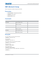
NET–Network Setup . . . . . . . . . . . . . . . . . . . . . . . . . . . . . . . . . . . . . . . . . . . . 114
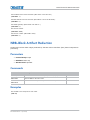
NRB–Block Artifact Reduction . . . . . . . . . . . . . . . . . . . . . . . . . . . . . . . . . . . . . . 115
NRD–General Noise Reduction . . . . . . . . . . . . . . . . . . . . . . . . . . . . . . . . . . . . . 116
NTR–Network Routing . . . . . . . . . . . . . . . . . . . . . . . . . . . . . . . . . . . . . . . . . . . 116
OPP–Odd Pixel Phase
. . . . . . . . . . . . . . . . . . . . . . . . . . . . . . . . . . . . . . . . . . . 117
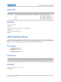
OSD–On Screen Display
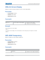
. . . . . . . . . . . . . . . . . . . . . . . . . . . . . . . . . . . . . . . . . 118
OST–OSD Transparency
. . . . . . . . . . . . . . . . . . . . . . . . . . . . . . . . . . . . . . . . . 118
PBC–PIP Border Color . . . . . . . . . . . . . . . . . . . . . . . . . . . . . . . . . . . . . . . . . . . 119
PBW–PIP Border Width . . . . . . . . . . . . . . . . . . . . . . . . . . . . . . . . . . . . . . . . . . 120
PDT–Peak Detector . . . . . . . . . . . . . . . . . . . . . . . . . . . . . . . . . . . . . . . . . . . . . 120
PHP–PIP Horizontal Position . . . . . . . . . . . . . . . . . . . . . . . . . . . . . . . . . . . . . . . 121
PHS–PIP Horizontal Size . . . . . . . . . . . . . . . . . . . . . . . . . . . . . . . . . . . . . . . . . 122
PIP–Picture in Picture . . . . . . . . . . . . . . . . . . . . . . . . . . . . . . . . . . . . . . . . . . . 122
PJH–Projector Hours . . . . . . . . . . . . . . . . . . . . . . . . . . . . . . . . . . . . . . . . . . . . 123
M Series Serial API Commands Technical Reference
020-100224-10 Rev. 1 (01-2015)
6
Content
PLK–User Lockouts . . . . . . . . . . . . . . . . . . . . . . . . . . . . . . . . . . . . . . . . . . . . . 124
PMT–Picture Mute . . . . . . . . . . . . . . . . . . . . . . . . . . . . . . . . . . . . . . . . . . . . . . 124
PNG–Ping . . . . . . . . . . . . . . . . . . . . . . . . . . . . . . . . . . . . . . . . . . . . . . . . . . . 125
PPA–Position Preset Aspect . . . . . . . . . . . . . . . . . . . . . . . . . . . . . . . . . . . . . . . 126
PPP–PIP Position Preset . . . . . . . . . . . . . . . . . . . . . . . . . . . . . . . . . . . . . . . . . . 127
PPS–Swap . . . . . . . . . . . . . . . . . . . . . . . . . . . . . . . . . . . . . . . . . . . . . . . . . . . 127
PRT–Serial Port . . . . . . . . . . . . . . . . . . . . . . . . . . . . . . . . . . . . . . . . . . . . . . . 128
PTL–Serial Protocol . . . . . . . . . . . . . . . . . . . . . . . . . . . . . . . . . . . . . . . . . . . . . 129
PVP–PIP Vertical Position . . . . . . . . . . . . . . . . . . . . . . . . . . . . . . . . . . . . . . . . . 129
PWR–Power . . . . . . . . . . . . . . . . . . . . . . . . . . . . . . . . . . . . . . . . . . . . . . . . . . 130
PXP–Pixel Phase . . . . . . . . . . . . . . . . . . . . . . . . . . . . . . . . . . . . . . . . . . . . . . . 131
PXT–Pixel Tracking . . . . . . . . . . . . . . . . . . . . . . . . . . . . . . . . . . . . . . . . . . . . . 132
RAL–Remote Access Level . . . . . . . . . . . . . . . . . . . . . . . . . . . . . . . . . . . . . . . . 133
RBL–Right Blanking
. . . . . . . . . . . . . . . . . . . . . . . . . . . . . . . . . . . . . . . . . . . . 134
RDB–Red Black Level
RDD–Red Drive
. . . . . . . . . . . . . . . . . . . . . . . . . . . . . . . . . . . . . . . . . . . 135
. . . . . . . . . . . . . . . . . . . . . . . . . . . . . . . . . . . . . . . . . . . . . . . 136
ROG–Red Odd Pixel Gain . . . . . . . . . . . . . . . . . . . . . . . . . . . . . . . . . . . . . . . . . 137
ROO–Red Odd Pixel Offset . . . . . . . . . . . . . . . . . . . . . . . . . . . . . . . . . . . . . . . . 138
RQR–RGB Quantization Range . . . . . . . . . . . . . . . . . . . . . . . . . . . . . . . . . . . . . 138
RTE–Real Time Events . . . . . . . . . . . . . . . . . . . . . . . . . . . . . . . . . . . . . . . . . . . 139
SHU–Shutter . . . . . . . . . . . . . . . . . . . . . . . . . . . . . . . . . . . . . . . . . . . . . . . . . 142
SIN–Select Input . . . . . . . . . . . . . . . . . . . . . . . . . . . . . . . . . . . . . . . . . . . . . . 143
SIZ–Size . . . . . . . . . . . . . . . . . . . . . . . . . . . . . . . . . . . . . . . . . . . . . . . . . . . . 144
SMP–Sampling Mode . . . . . . . . . . . . . . . . . . . . . . . . . . . . . . . . . . . . . . . . . . . . 144
SOR–Screen Orientation . . . . . . . . . . . . . . . . . . . . . . . . . . . . . . . . . . . . . . . . . 145
SPS–Splash Screen . . . . . . . . . . . . . . . . . . . . . . . . . . . . . . . . . . . . . . . . . . . . . 146
SPT–Split Screen . . . . . . . . . . . . . . . . . . . . . . . . . . . . . . . . . . . . . . . . . . . . . . 147
SST–Status . . . . . . . . . . . . . . . . . . . . . . . . . . . . . . . . . . . . . . . . . . . . . . . . . . 148
STD–Video Standard . . . . . . . . . . . . . . . . . . . . . . . . . . . . . . . . . . . . . . . . . . . . 149
SZP–Size Presets . . . . . . . . . . . . . . . . . . . . . . . . . . . . . . . . . . . . . . . . . . . . . . 150
TBL–Top Blanking . . . . . . . . . . . . . . . . . . . . . . . . . . . . . . . . . . . . . . . . . . . . . . 151
TDD–3D Emitter Delay
. . . . . . . . . . . . . . . . . . . . . . . . . . . . . . . . . . . . . . . . . . 152
TDI–3D Sync Input . . . . . . . . . . . . . . . . . . . . . . . . . . . . . . . . . . . . . . . . . . . . . 153
TDM–3D Mode . . . . . . . . . . . . . . . . . . . . . . . . . . . . . . . . . . . . . . . . . . . . . . . . 153
TDN–Invert 3D Input
TDO–3D Sync Out
. . . . . . . . . . . . . . . . . . . . . . . . . . . . . . . . . . . . . . . . . . . 155
. . . . . . . . . . . . . . . . . . . . . . . . . . . . . . . . . . . . . . . . . . . . . 155
TDT–3D Test Pattern . . . . . . . . . . . . . . . . . . . . . . . . . . . . . . . . . . . . . . . . . . . . 156
TED–Twin HDMI EDID Type Selection . . . . . . . . . . . . . . . . . . . . . . . . . . . . . . . . 157
M Series Serial API Commands Technical Reference
020-100224-10 Rev. 1 (01-2015)
7
Content
TIL–Tiling Control . . . . . . . . . . . . . . . . . . . . . . . . . . . . . . . . . . . . . . . . . . . . . . 158
TMD–Time and Date . . . . . . . . . . . . . . . . . . . . . . . . . . . . . . . . . . . . . . . . . . . . 158
TNT–Tint . . . . . . . . . . . . . . . . . . . . . . . . . . . . . . . . . . . . . . . . . . . . . . . . . . . . 159
TTM–THIC Transmitter Mode Configuration
TXE–Texture Enhancement
. . . . . . . . . . . . . . . . . . . . . . . . . . . . 160
. . . . . . . . . . . . . . . . . . . . . . . . . . . . . . . . . . . . . . . 161
UID–User ID . . . . . . . . . . . . . . . . . . . . . . . . . . . . . . . . . . . . . . . . . . . . . . . . . 161
VBL–Video Black Input
VRT–Vertical Position
. . . . . . . . . . . . . . . . . . . . . . . . . . . . . . . . . . . . . . . . . . 162
. . . . . . . . . . . . . . . . . . . . . . . . . . . . . . . . . . . . . . . . . . . 163
VST–Vertical Search . . . . . . . . . . . . . . . . . . . . . . . . . . . . . . . . . . . . . . . . . . . . 163
WRP–Warp Selection . . . . . . . . . . . . . . . . . . . . . . . . . . . . . . . . . . . . . . . . . . . . 164
YNF–Yellow Notch Filter . . . . . . . . . . . . . . . . . . . . . . . . . . . . . . . . . . . . . . . . . . 165
ZOM–Lens Zoom Position Adjustment . . . . . . . . . . . . . . . . . . . . . . . . . . . . . . . . 166
M Series Serial API Commands Technical Reference
020-100224-10 Rev. 1 (01-2015)
8
Introduction
This document describes the serial protocol, consisting of ASCII text messages, used to control an
M Series projector remotely.
Connection and use
Once you have connected your computer to either the RS232 IN or RS422 IN port (depending on
which standard is supported by your computer) or to the Ethernet port on a projector, you can
remotely access projector controls and image setups, issue commands or queries, and receive
replies. Use these bi-directional messages to:
•
Control multiple projectors
•
Obtain a projector’s status report
•
Diagnose performance problems
i
• Refer to the User Manual provided with the projector for all cable requirements and other
connection details.
• Some commands are operational only when projector is powered up.
Understanding message format
Messages can be one of three types:
•
Set—A command to set a projector parameter at a specific level, such as changing to a certain
channel.
•
Request—A request for information, such as what channel is currently in use.
•
Reply—The projector returns the data in response to a request or as confirmation of a
command.
All remote control information passes in and out of the projector as a simple text message
consisting of a three letter command code, an optional four letter subcode and any related data.
When a parameter for a specific source is being accessed, the four letter subcode is added on to the
command code. A number of optional features (message acknowledges, checksums, and network
addressing) can be included.
Generally, most commands include 0 or 1 data fields or parameters. Where applicable, a message
may expand to include additional parameters of related details.
M Series Serial API Commands Technical Reference
020-100224-10 Rev. 1 (01-2015)
9
Introduction
The smallest step size for any parameter is always 1. For some controls (such as Size) the value
displayed on the screen has a decimal point (for example, 0.200 to 4.000). In this case, the values
used for the serial communications is an integer value (for example, 200 to 4000), not the decimal
value seen on the screen.
Regardless of message type or origin, all messages use the same basic format and code. Opening
and closing round brackets (parentheses) surround each message, see Basic message structure on
page 10.
Message formats
Source
Message Format
Function
Examples
From Controller
(Code Data)
SET (set contrast of main image to
500)
(CON500) or (CON 500)
(Code+Subcode Data)
SET (set contrast of PIP image to
500)
(CON+PIIP500) or (CON +PIIP
500)
(Code ?)
REQUEST (what is current
contrast?)
(CON?) or (CON ?)
(Code+Subcode ?)
REQUEST (what is contrast of PIP
image?)
(CON+PIIP?) or (CON+PIIP ?)
(Code Data)
REPLY (contrast is 500)
(CON!500)
(Code+Subcode Data)
REPLY (PIP contrast is 500)
(CON+PIIP!500)
From Controller
From Projector
Basic message structure
The following component fields comprise a standard ASCII message. Optional fields, such as extra
characters for special modes, restrictions or added functionality, are shown in italics, with the
exception of Notes.
•
Start and end of message: Every message begins with the left bracket character and ends
with the right bracket character.
If the start character is received before an end character of the previous message, the partial
(previous) message is discarded.
•
Prefix characters (optional): For acknowledgement that the projector has responded, and/or
to maximize message integrity, insert one or two special characters before the three-character
function code:
$—Simple Acknowledgment, which causes a dollar sign ($) character to be sent from the
projector when it has finished processing the message, see Maximizing message integrity on
page 13.
#—Full Acknowledgment, which causes an echo of the message as a reply to be sent from the
projector when it has finished processing the message, see Maximizing message integrity on
page 13.
&—Checksum, which allows a checksum to be put as the last parameter in the message for
verification at the projector, see Maximizing message integrity on page 13.
•
Projector numbers (optional): To control a selected projector or controller within a group,
include its assigned number or address just before the three-character ASCII function code, see
M Series Serial API Commands Technical Reference
020-100224-10 Rev. 1 (01-2015)
10
Introduction
Network operation on page 16.
•
Function code: The projector function you want to work with, such as channel selection or
gamma, is represented by a three-character ASCII code (A-Z, upper or lower case). This
function code appears immediately after the leading bracket that starts the message. In
messages sent to the projector that do not have a subcode, a space between the function code
and the first parameter (or special character) is optional.
•
+Subcode: The projector function you want to work with may have one or more subcodes that
allow you to select a specific source, image, channel or subfunction. The subcode is represented
by a four-character ASCII code (A-Z, upper or lower case, and 0-9). This subcode appears
immediately after the function code, with a plus sign (+) character to separate the code and
subcode. If there is no subcode, the plus sign (+) is also omitted. In messages sent to the
projector that do have a subcode, a space between the subcode and the first parameter (or
special character) is optional.
•
Request/reply symbols: If the controller is requesting information from the projector, a
question mark (?) appears directly after the function code. If the projector is replying, an
exclamation mark (!) appears directly after the function code. For set messages to the
projector, neither of these characters appear—data directly follows the code and subcode.
•
Other special functions (optional): To add functionality to the current message, include one
or more of the following special characters between the function code/subcode and the first
parameter. If more than one, add them in any order, see Flow control on page 16.
•
C
Control Class Inquiry
D
Default value/Text
E
Enable Control Inquiry
G
Access Group Inquiry
H
Return the Help text for a control
L
Return a list of options for list controls
M
Find min/max adjustments (such as range)
N
Return the name of the control
T
Return the type of control (such as Slidebar and so on)
Data: The value for a given projector state, such as on or off, appears in ASCII-decimal format
directly after the request/reply symbol. You can add an optional space after the symbol—such
as before the data—in a set message, but data in replies follow the exclamation mark (!)
symbol without a space. Other details to remember about data:
•
All values returned by the projector (reply messages) have a fixed length, regardless of
the actual value. For a specific parameter the length is always be the same (for example,
contrast is always returned as three characters, projector number is always returned as
five characters). The minimum parameter size is three characters. Values less than the
predefined size are padded with leading zeros as needed. Parameters which have
negative signs are zero padded after the negative sign, and have one less digit to make
space for the sign.
M Series Serial API Commands Technical Reference
020-100224-10 Rev. 1 (01-2015)
11
Introduction
•
•
If entering a negative number, there must be a space between the code/subcode and the
value for example (CRM3) and (CRM 3) can both be used when the number is positive.
(CRM -2) is acceptable, but (CRM-2) is not.
•
Data in set messages to the projector do not require padding with zeros.
•
Within each message, multiple parameters of data must be separated by one space
character.
•
Text parameters such as channel names are enclosed in double quotes following the
data, as in Name.
Text parameters: Most data is simply a numerical value, however some messages also
require text. For example, a channel naming message typically includes a text-based name—
enclose this text in double quotation marks, as in Tilt the Wagon. Use all characters as required
except for the following special characters shown in the left column below—these require a twocharacter combination, see below.
Special characters for text
If you want this...
Enter this...
Description
\
\\
Backslash
”
\”
Quote
(
\(
Left Bracket
)
\)
Right Bracket
0x0A
\n
New line —If the text can be displayed on more than one line, this
sets the line break.
\h##
Sends one arbitrary code defined by the two hexadecimal digits ##
Sample messages and their meaning
The following sections provide sample messages and outline their meaning.
M Series Serial API Commands Technical Reference
020-100224-10 Rev. 1 (01-2015)
12
Introduction
For a single projector
Message Format
Function
Example
(Code Data)
SET (set contrast of main image to 500)
(CON500)
(Code+Subcode Data)
SET (set contrast of PIP image to 500)
(CON+PIIP500)
(Code?)
REQUEST (what is current contrast?)
(CON?)
(Code+Subcode?)
REQUEST (what is contrast of PIP image?)
(CON+PIIP?)
(Code!Data)
REPLY (contrast is 64)
(CON!64)
(Code+Subcode!Data)
REPLY (PIP contrast is 64)
(CON+PIIP!64)
($Code Data)
SET AND ACKNOWLEDGE MESSAGE (message
processed?)
($CON64)
SET WITH CHECKSUM
(&CON64 240)
(&Code+Subcode Data
Checksum)
For a specific projector within a network with one controller present
Message Format
Function
Example
(Dest Addr Code Data)
SET (turn projector #5 on)
(5pwr1)
($Dest Addr Code Data)
SET AND ACKNOWLEDGE MESSAGE (message processed?ffr55)
($5pwr1)
For a specific projector within a network with multiple controllers present
Message Format
Function
Example
(Dest Addr
REQUEST (get contrast from projector #5 to controller #2)
(5 2con?)
SET AND ACKNOWLEDGE MESSAGE (is message from
controller #2 processed by projector #5)
($5 2con?)
REPLY (from projector #5 to controller #2: contrast is 64)
(002 005con!064)
($Dest Addr
(Dest Addr
Src Code?)
Src Code Data)
Src Code!Data)
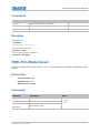
What is sent in a message
Although you send and read messages as strings of ASCII characters, the actual message travels as
a sequence of bytes. Each character in this sequence requires 1 byte. See the example below,
which illustrates a lamp limit is 2000 hours reply from the projector.
ASCII =
(
L
P
L
!
2
0
0
0
)
HEX =
0x28
0x4
0x50
0x28
0x21
0x32
0x30
0x30
0x30
0x29
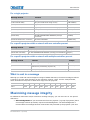
Maximizing message integrity
For additional reassurance and/or maximum message integrity, you can insert one or two special
characters:
•
Acknowledgements: If you want assurance from the projector (or group of projectors) that a
set message has been processed, request an acknowledgement. The acknowledgement is
returned after the message has been received and fully executed by the projector (such as in
M Series Serial API Commands Technical Reference
020-100224-10 Rev. 1 (01-2015)
13
Introduction
the case of a source switch it is not sent until the switch is complete). If the message cannot be
executed for some reason (such as invalid parameters, time-out, and so on) a NAK is returned
instead (not-acknowledge). Requesting an acknowledgement serves no purpose when included
in a request message, as the acknowledgement is redundant to the actual reply from the
projector. However, if requested, the dollar sign ($) acknowledgement from the projector
follows the reply.
There are two types of acknowledgements:
•
Simple Acknowledgements: Insert a dollar sign ($) character just after the start code
bracket. This only returns a $. This only returns a dollar sign ($) on success, or a caret
(^) on failure (NAK).
•
Full Acknowledgements: Insert a hash (#) character just after the start code bracket.
This returns the message sent, as a reply.
This is a quick way to confirm success with set messages, and is particularly useful with longdistance communication links or where the projectors and/or images are not visible from the
controller. Acknowledgements can also be a type of flow control.
•
Checksums: For maximum message integrity, add a checksum character ampersand (&) just
after the start code bracket. You must then also include the correct checksum total (0-255) just
before the end code bracket. Make sure to add a space before the calculated checksum to
separate it from the last data parameter:
The checksum is the low byte of the sum of the ASCII values of all characters between the start
bracket and the beginning of the checksum, but not including either. It does include the space
in front of the checksum. Calculate the checksum for the above set contrast to 64 command as
follows:
CHECKSUM EXAMPLE = & + c + o + n + 6 + 4 + ‘space’
= 26h+63h +6Fh +6E h +36h +$34h +$20h
= 01F0h
= F0h when only the low byte is used
= 240
The projector collects all of the message bytes as defined in the first byte of the message, then
creates its own checksum value for comparison with the checksum included in the controller’s
message. If the values match, the message is considered to have been correctly received;
otherwise, the message is discarded.
i
• h indicates a hex number.
• If a request message has a checksum so does the reply.
• If using both acknowledge and checksum, either character can occur first.
Message errors
If a command cannot be performed (for example, syntax error), you receive a descriptive error
indicating the problem. For example: (ITP)
(65535 00000 ERR00005 "ITP: Too Few Parameters")
M Series Serial API Commands Technical Reference
020-100224-10 Rev. 1 (01-2015)
14
Introduction
For more examples of a descriptive error, see below.
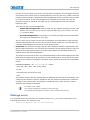
Descriptive error
Error Code
Error Description
Error Code
Error Description
3
Invalid Parameter
107
Exceeded List Size
4
Too Many Parameters
108
Exceeded Text Size
5
Too Few Parameters
109
Invalid Pointer
6
Channel not found
110
Communication Timeout
7
Command not executed
111
Communications Failure
8
Checksum error
112
Failed to set Hardware
9
Unknown request
113
Bad File
10
Error receiving serial data
114
Memory Failure
101
Control Not Found
115
Not Implemented
102
Subcontrol Not Found
116
Invalid Security Token
103
Wrong Control Type
117
Invalid Access Group
104
Invalid Value
118
System Busy - Try Again Later
105
Disabled Control
??
Unknown Error
106
Invalid Language
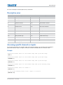
Accessing specific channels or inputs
For several commands (for example, ASR, Auto Channel Select) you can direct the message to
particular channel, input or image. To do this, include a subcode after the function code.
Example
Enable Auto Channel Select for the channel being used by the Main image.
(ASR 1)
Enable Auto Channel Select for the channel being used by the Main image.
(ASR+MAIN 1)
Enable Auto Channel Select for the channel being used by the PIP image.
(ASR+PIIP 1)
Enable Auto Channel Select for the channel being used by the Secondary image.
(ASR+SECD 1)
Enable Auto Channel Select for channel 3.
(ASR+C003 1)
Set the bottom blanking value on slot 1 input 2 to value 30.
(BBL+IN12 30)
M Series Serial API Commands Technical Reference
020-100224-10 Rev. 1 (01-2015)
15
Introduction
You can set parameters from a specific channel or input if that parameter is stored separately for
each channel or input. This function cannot be used for parameters that are specified for the
projector as a whole such as projector address. The serial commands listed in the document specify
which subcodes are applicable to each function.
The picture-in-picture and secondary images both refer to the image on the secondary image path.
Depending on your projector model type, either picture-in-picture or secondary commands are
applicable to this image. However, for serial commands, PIIP and SECD can be used
interchangeably as shown within this document.
Flow control
Normally messages can be sent to the projector before processing of earlier messages is
complete—the projector stores messages in a buffer until ready to process. However, if a series of
messages is sent. the projector may not be able to process them as fast as they arrive and the
buffer becomes full. If this happens, the projector sends the 13h (Xoff) code to instruct the
controller (or any devices preparing to transmit) to cease transmission. At this point, the controller
must respond immediately and send no more than 10 extra characters or they may be lost (such
as, the projector can accommodate the receipt of up to 10 more bytes after it sends 13h (Xoff)).
When the buffer is once again available, the projector sends a 11h (Xon) command to resume
transmission.
Xon and Xoff controls apply to both directions of communication. The projector does not send more
than three characters after it has received a 13h (Xoff) code.
i
Network operation
Up to 1000 projectors can be linked together in a chain with the OUT port on one connected to the
IN port on the next. A controller connected to the IN port on the first projector can control them all,
either by broadcasting messages which have no address and are thus seen by all projectors, or by
directing messages to specific projector addresses.
Message for specific projector
To work with a specific projector in a group, the projectors must first be assigned a unique ID—
either a projector number or an Ethernet IP address. Insert the number of the target projector
between the starting bracket and the three-character ASCII code.
(
Addr
Code
Data
)
Each projector compares the message address with its own address and, if matching, responds and
processes the message. If the address does not match, the message is passed on until it reaches
the intended projector.
Message for projector from a specific controller
Although messages without an address are always broadcast, you can also broadcast by including
the reply destination address 65535. This ensures that replies go to a specific controller address
rather than being broadcast. The projector also includes its address.
(
Dest
Src
Code
Data
)
M Series Serial API Commands Technical Reference
020-100224-10 Rev. 1 (01-2015)
16
Introduction
Message for specific projector from a specific controller
If you have more than one controller on a network, ensure to include both a source address and a
destination address. With a single controller on the network, its address is never required. Place the
source address between the destination address and three-character code, including a space before
and after as shown.
Replies from a projector do not contain an address unless the request message includes both a
destination address and a source address—such as, a reply to a request having only a destination
address does not have any source address.
i
(
Dest
Src
Code
Data
)
Examples
Command
Message from
Controller
Reply from Projector
Turn Projector #5 on.
(5pwr1)
{none}
What is the contrast level in Projector 30?
(30con?)
(CON!127)
Return Contrast from Projector #30 to Controller #2. (30 2con?)
(00002 00030con!127)
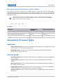
Description of control types
Subclasses
•
Power Down Controls—Controls are accessible when the projector is in Standby power mode
(such as power off) as well as when powered on.
•
Power Up Controls—Controls are only accessible when the system electronics are fully
powered (not necessarily lamp on).
Control groups
•
Unsaved Controls—Controls are not saved to flash. The settings are not maintained between
power sessions.
•
Saved Controls—Controls are saved to flash. The settings are persistent between power
sessions.
•
Preference Controls—Controls are transferable from one projector to another, for example:
NET+SUB0 (projector subnet).
•
Configuration Controls—Controls are projector specific settings. They are non-transferable
between projectors, for example: NET+ETH0 (projector IP address).
•
Channel Controls—Settings are specific to a particular input signal, for example: BRT (signal
brightness).
M Series Serial API Commands Technical Reference
020-100224-10 Rev. 1 (01-2015)
17
Introduction
•
Option Card Controls—Settings are specific to a particular option card type/slot combination.
Access levels
•
Operator—Command is available at the operator level log in.
•
Advanced—Command is available at the advanced operator level log in.
•
Admin—Command is available at the administrator level log in.
•
Service—Command is available at the service level log in.
M Series Serial API Commands Technical Reference
020-100224-10 Rev. 1 (01-2015)
18
M Series Serial API
Commands
The M Series serial API commands can be used to modify projector settings.
ACE–Auto Color Enable
Automatically selects Color Enable based on the control being adjusted. If enabled, the projector
can automatically change the color enable control when the user is using the on-screen display
interface to adjust controls such as input levels, odd pixel, and brightness uniformity. This is an
unsaved control, which can only be set when powered on and only affects the operation of the on
screen menus.
Parameters
•
Control Group: Preference
•
Subclass: Power Up
•
Access Level: Operator
Commands
Command
Description
Values
ACE <0 | 1>
Enables or disables the auto color controls.
0 = Disables Auto Color
1 = Enables Auto Color
Examples
Disable Auto Color.
(ACE 0)
Enable Auto Color.
(ACE 1)
M Series Serial API Commands Technical Reference
020-100224-10 Rev. 1 (01-2015)
19
M Series Serial API Commands
ACO–Adaptive Contrast
Dynamically expands the contrast of the output image producing vibrant images with seamless
response to scene changes and fades. The adaptive contrast function implements a dynamic nonlinear mapping between the input and output contrast levels based on frame-by-frame luminance
histogram measurement of the input image.
Parameters
•
Control Group: Input
•
Subclass: Power Up
•
Access Level: Operator
Commands
Command
Description
Values
ACO+INxy
Sets the adaptive contrast for slot x, input y.
0 to 15
ACO+MAIN
Sets the adaptive contrast for main video.
0 to 15
ACO+PIIP
Sets the adaptive contrast for picture-in-picture or secondary video.
0 10 15
ACO+SECD
Examples
Set adaptive contrast for main image to 50% strength.
(ACO 8)
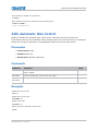
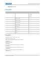
ACT–Active Window
Defines the input active window in pixels. The production aperture is available for analog sources
only, but not for decoded analog signals. The aperture is set once on every auto setup or on new
signal detection when a channel for that signal is not present. The aperture defines the maximum
window in which blanking controls can be opened up to, relative to the active portion of the signal.
This is a read-only control.
Parameters
•
Control Group: Input
•
Subclass: Power Up
•
Access Level: Operator (Read-only)
M Series Serial API Commands Technical Reference
020-100224-10 Rev. 1 (01-2015)
20
M Series Serial API Commands
Commands
Command
Description
Values
ACT+INxy
Sets the adaptive contrast for slot x, input y.
-
ACT+MAIN
Sets the adaptive contrast for main video.
-
ACT+PIIP
Sets the adaptive contrast for picture-in-picture or secondary video.
-
ACT+SECD
Examples
Return the active window for the main video.
(ACT ?)
Return the active window for the PIP video.
(ACCT+PIP?)
Return the active window for slot 1, input 2.
(ACT+IN12?)
ADR–Address
Sets or queries Device Address on ASCII Protocol network. Required only for RS232 connections
daisy chained to allow directed messages.
Parameters
•
Control Group: Preference
•
Subclass: Power Down
•
Access Level: Operator
Commands
Command
Description
ADR <value>
Sets the projector address to <value>.
Values
0 to 999
65535 = Reserved broadcast address
Examples
Set all devices to address 0.
(65535 ADR 0)
M Series Serial API Commands Technical Reference
020-100224-10 Rev. 1 (01-2015)
21
M Series Serial API Commands
Set first device at address 0 to address to 5.
(0 ADR 5)
Query address for all devices and return results to address 1001.
(65535 1001ADR?)
(01001 00005ADR!005)
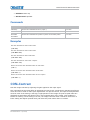
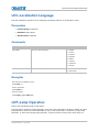
AGC–Automatic Gain Control
Enables or disables the automatic gain control (AGC). Using this control the decoder can
automatically track the sync amplitude of the incoming signal. Turn this control off if you experience
strange color artifacts, indicating an incompatibility between the source and the AGC.
Parameters
•
Control Group: Input
•
Subclass: Power Up
•
Access Level: Operator (Read-only)
Commands
Command
Description
Values
AGC+INxy
Sets the automatic gain control for slot x, input y to the specified state of either
enable or disable.
-
AGC+MAIN
Sets the automatic gain control for the main image.
-
AGC+PIIP
Sets the automatic gain control for picture-in-picture or secondary video.
-
AGC+SECD
Examples
Enable AGC on main video.
(AGC 1)
Disable AGC on main video.
(AGC+MAIN 0)
Enable on PIP video.
(AGC+PIIP 1)
Return the current AGC state on main video.
(AGC?)
M Series Serial API Commands Technical Reference
020-100224-10 Rev. 1 (01-2015)
22
M Series Serial API Commands
Return the current AGC state on PIP video.
(AGC+PIIP ?)
Return the current AGC state on slot 1 input 2.
(AGC+IN12 ?)
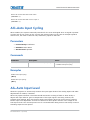
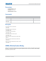
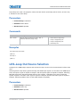
AIC–Auto Input Cycling
When enabled, the system continually searches for the next valid signal when no signal is present
or when loss of sync occurs on the current user selected input. In the case of multiple signals to
choose from, the order is based on slot, followed by inputs on that slot.
Parameters
•
Control Group: Preference
•
Subclass: Power Down
•
Access Level: Operator
Commands
Command
Description
Values
AIC <0 | 1>
Enables or disables auto input cycling.
0 = Disables auto input cycling
1 = Enables auto input cycling
Examples
Disable auto input cycling.
(AIC 0)
Enable auto input cycling.
(AIC 1)
AIL–Auto Input Level
Allows the projector to continuously monitor the input signal levels of the analog inputs and make
adjustments as needed, if enabled.
When the projector detects a level that would lead to the crushing of black or white levels, it
adjusts the input offset or gain to compensate. If the input signal is not being crushed, the
projector does nothing. Only use the Auto Input Level feature when the current source requires
further input level adjustment. At least 12 consecutive white pixels must be in the image to use
Auto Input Levels. The monitor period runs for 10 seconds after being issued. Auto setup or source
switching stops the level period.
M Series Serial API Commands Technical Reference
020-100224-10 Rev. 1 (01-2015)
23
M Series Serial API Commands
To use this control, turn it on, wait for the black level and drive values to stabilize, and turn it off or
wait for the 10 seconds.
When Auto Input level is turned off, the current drive and black level values are maintained. This
control only applies to analog BNC or Dual DVI cards.
Parameters
•
Control Group: Unsaved
•
Subclass: Power Up
•
Access Level: Operator
Commands
Command
Description
Values
AIL+MAIN
Performs auto input level on the main image.
-
AIL+PIIP
Performs auto input on picture-in-picture or secondary image.
-
AIL+SECD
Examples
Perform auto input level on the main image.
(AIL 1)
Perform auto input level on the picture-in-picture image.
(AL+PIIP 1)
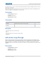
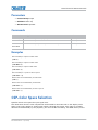
ALT–Active Loop-Through
Ensures that video signals continue to be looped out when the projector enters standby power
mode, in situations where a Twin HDMI Input card is used to loop signals out to another projector.
When the projector is in standby mode (and this feature is enabled), limited channel control is
available—inputs can be switched, can perform Auto Setup, and some limited input settings can be
modified.
Parameters
•
Control Group: Preference
•
Subclass: Power Down
•
Access Level: Operator
M Series Serial API Commands Technical Reference
020-100224-10 Rev. 1 (01-2015)
24
M Series Serial API Commands
Commands
Command
Description
Values
ALT <0 | 1>
Enables or disables active loop-through.
0 = Disables standby active loop-through
1 = Enables standby active loop-through
Examples
Enable standby active loop-through.
(ALT 1)
Disable standby active loop-through.
(ALT 0)
Get the current standby active loop-through setting.
(ALT?)
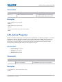
APJ–Active Projector
Enables or disables temporarily the IR and wired keypad Inputs to a specific projector in a network
of projectors. When a projector is disabled, the only key that works is PROJ. The next time the
projector is powered up again, it reverts to fully enabled. The built-in keypad is always fully
functional. This control does not overwrite the Front IR, Back IR and Wired Keypad settings.
To temporarily disable keypad access to this projector, set to 0.
Parameters
•
Control Group: Unsaved
•
Subclass: Power Down
•
Access Level: Operator
Commands
Command
Description
Values
APJ <0 | 1>
Enables or disables IR remote control
access to the projector.
0 = Disables IR remote control to the projector
1 = Enables IR remote control to the projector
Examples
Is the projector IR remote control active or not.
(APJ?)
M Series Serial API Commands Technical Reference
020-100224-10 Rev. 1 (01-2015)
25
M Series Serial API Commands
Projector is active (IR remote control are enabled).
(APJ 1)
Projector is not active (IR remote control are temporarily disabled).
(APJ 0)
APW–Auto Power Up
Automatically changes from stand-by mode to Power On mode when the A/C switch is turned on, if
an AC interruption has occurred in the previous power cycle.
Parameters
•
Control Group: Preference
•
Subclass: Power Down
•
Access Level: Operator
Commands
Command
Description
APW <0 | 1>
Automatically powers up the projector to the on state.
Values
0 = Disables auto power up
1 = Enables auto power up
Examples
Projector remains in Standby mode until the user presses the power key.
(APW 0)
Projector auto powers up when A/C power is switched on if it was in a powered on state (such as not in standby
mode) when the A/C power was powered off in the previous power cycle.
(APW 1)
ARO–Aspect Ratio Overlay
Enables or disables the aspect ratio layer over image layer.
Parameters
•
Control Group: Unsaved
•
Subclass: Power Up
M Series Serial API Commands Technical Reference
020-100224-10 Rev. 1 (01-2015)
26
M Series Serial API Commands
•
Access Level: Operator
Commands
Command
Description
ALT <0 | 1>
Enables or disables the aspect ratio overlay.
Values
0 = Disable the aspect ratio overlay
1 = Enables the aspect ratio overlay
Examples
Turn on Aspect Ratio Overlay.
(ARO 1)
Turn off Aspect Ratio Overlay
(ARO 0)
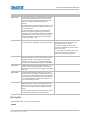
ASH–Auto Shutdown
Enters a Power Saving mode in which the lamps dim and the shutter closes, when Auto Shutdown
mode has been selected and no projector activity has been seen for the activation time-out period.
If this condition persists for an additional time-out period the projector automatically goes to
standby. The presence of any activity within this is combined interval cancels Auto Shutdown and
returns the projector to normal operation.
Parameters
•
Control Group: Saved
•
Subclass: Power Down
•
Access Level: Operator
Commands
Command
Description
ASH <0 | 1>
Enables or disables the Auto Shutdown mode.
Values
0 = Turns off Auto Shudown mode
1 = Turns on Autom Shudown mode
ASH+SBTO
Sets the uninterrupted time-out period that must
elapse before projector enters Standby mode (the
second time-out period or Standby time-out).
-
ASH+ALTO
Sets the uninterrupted time-out period that must
elapse time of activity loss until Auto Shutdown is
activated (the first time-out period or Activation timeout).
-
M Series Serial API Commands Technical Reference
020-100224-10 Rev. 1 (01-2015)
27
M Series Serial API Commands
Examples
Turn on Auto Shutdown mode.
(ASH 1)
Turn off Auto Shutdown mode.
(ASH 0)
Set standby time-out to 10 minutes.
(ASH+SBTO 10)
Set source activity loss time-out to 10 minutes.
(ASH+ALTO 10)
ASR–Auto Channel Select
Allows the projector to select the channel memory best suited to the input signal. If the current
channel does not support Auto Channel Select, the projector does not attempt to select a new
channel when the signal changes. If the current channel does support Auto Channel Select, upon
signal detection, an existing channel is chosen. If a match is not found, a new channel is created.
Parameters
•
Control Group: Channel
•
Subclass: Power Up
•
Access Level: Operator
Commands
Command
Description
Values
ASR+C0xx
Enables or disables Auto Channel Select on the
specified channel.
xx = Channel number from 01 to 99
ASR+MAIN
Enables or disables Auto Channel Select on the
channel being used by main.
-
ASR+PIIP
Enables or disables Auto Channel Select on the
channel being used by PIP or secondary.
-
ASR+SECD
Examples
Get Auto Channel Select state for channel being used by main.
(ASR?)
M Series Serial API Commands Technical Reference
020-100224-10 Rev. 1 (01-2015)
28
M Series Serial API Commands
Get Auto Channel Select state for channel being used by main.
(ASR+MAIN?)
Get Auto Channel Select state for channel being used by PIP.
(ASR+PIIP?)
Enable Auto Channel Select for the channel being used by main.
(ASR 1)
Enable Auto Channel Select for the channel being used by PIP.
(ASR+PIIP 1)
Disable Auto Channel Select for the channel being used by main.
(ASR+MAIN 0)
Disable Auto Channel Select for channel 1.
(ASR+C001 0)
ASU–Auto Setup
Automatically readjusts various video controls for the active video source to produce an optimal
image on screen.
If main and PIP/secondary video are using the same channel, the auto setup acts on both,
regardless of the sub-code being used.
In some cases for analog video, the user can select the format that best suits their source. This
selection helps the auto setup get the correct settings for the tracking and phase controls for analog
sources containing the same number of active lines but with different aspect ratios.
•
All digital and decoder option cards do not support options for auto setup as digital hardware
provides enough information to perform the correct auto setup.
•
Analog PC graphics sources (four/five-wire sync) present a list of formats based on the current
active lines detected in the video.
•
Analog Video Sources (three wire sync on green) always have the options standard and
advanced. Video sources use a look up table to determine their format based on video
standards. The Advanced auto setup selection measures the start pixel and start line whereas
Standard uses the table values as is.
Parameters
•
Control Group: Unsaved
•
Subclass: Power Up
•
Access Level: Operator
M Series Serial API Commands Technical Reference
020-100224-10 Rev. 1 (01-2015)
29
M Series Serial API Commands
Commands
Command
Description
Values
ASU
Performs auto setup on the active video source.
-
ASU+MAIN
Performs a standard auto setup on the main video.
-
ASU+PIIP
Performs a standard auto setup on the picture-inpicture or secondary video.
-
Hides temporary image artifacts that may appear
during the auto setup procedure.
0 = Disables freezing the image during
auto setup
ASU+SECD
ASU+FRZE
1 = Freezes the image during auto setup
Examples
Perform auto setup on the active video source.
(ASU)
Perform standard auto setup on main video.
(ASU)
Freeze image during auto setup.
(ASU+FRZE 1)
Disable image freezing during auto setup.
(ASU+FRZE 0)
Perform standard auto setup on main video.
(ASU+MAIN)
Perform standard auto setup on PIP.
(ASU+PIIP)
BBL–Bottom Blanking
Sets the number of lines to blank (turn to black) at the bottom of the image to blank out any
unwanted data near the bottom edge of the image.
A positive amount of blanking makes the image smaller. A negative amount of blanking makes the
image larger. Negative blanking is only applicable to analog signals, when the auto setup cannot set
the image size correctly. Christie recommends not using negative blanking, but to run auto setup
again, ensuring that the content has active pixels on each edge of the image. The maximum
amount of bottom blanking allowed is half the image height minus 10. For negative blanking, the
image size can only be increased to the limit of the sync.
Parameters
•
Control Group: Input
•
Subclass: Power Up
M Series Serial API Commands Technical Reference
020-100224-10 Rev. 1 (01-2015)
30
M Series Serial API Commands
•
Access Level: Operator
Commands
Command
Description
Values
BBL+INxy
Sets the bottom blanking for slot x, input y.
-
BBL+MAIN
Sets the bottom blanking for the main image.
-
BBL+PIIP
Sets the bottom blanking for the picture-in-picture or secondary image.
-
BBL+SECD
Examples
Set bottom blanking to 40 on main video.
(BBL 40)
Set bottom blanking to 40 on main video.
(BBL+MAIN 40)
Set bottom blanking to 40 on PIP video.
(BBL+PIIP 40)
Set bottom blanking to 40 on slot 3 input 2.
(BBL+IN32 40)
Returns the bottom blanking value on main video.
(BBL?)
Returns the bottom blanking value on PIP video.
(BBL+PIIP?)
Returns the bottom blanking value on slot 1 input 2.
(BBL+IN12?)
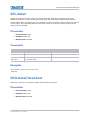
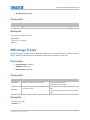
BDR–Baud Rate
Sets the baud rate for a serial communications port. The default communications settings for all
ports is eight data bits, no parity.
Parameters
•
Control Group: Preference
•
Subclass: Power Down
•
Access Level: Advanced
M Series Serial API Commands Technical Reference
020-100224-10 Rev. 1 (01-2015)
31
M Series Serial API Commands
Commands
Command
Description
Values
BDR+PRTA <value>
Sets the baud rate for the RS232-IN
port.
0 = 1200
BDR+PRTB <value>
Sets the baud rate for the RS232-OUT
port.
2 = 9600
BDR+PRTC <value>
Sets the baud rate for the RS422 port.
4 = 38400
1 = 2400
3 = 19200 (Default for RS422)
5 = 57600
6 = 115200 (Default for RS232 and RS232
OUT)
Examples
Set baud rate on port A to 115200 bits per second.
(BDR+PRTA 6)
Get baud rate.
(BDR+PRTA?)
(BRD+PRTA!"115200")
BGC–Base Gamma Curve
Selects the gamma table.
You can select from one of the standard tables, or select an arbitrary gamma table downloaded into
the projector. Use a separate PC utility to do this. The 2.22 table is a power curve. The standard
table is a modified 2.22 curve with an optimized linear portion in the low end of the curve. This is
the same as selecting a custom table and setting the function to be 2.22 and the slope to be 1.0.
Selecting Gamma Function from the list enables the Gamma Function and Gamma Slope controls.
Parameters
•
Control Group: Input
•
Subclass: Power Up
•
Access Level: Operator
M Series Serial API Commands Technical Reference
020-100224-10 Rev. 1 (01-2015)
32
M Series Serial API Commands
Commands
Command
Description
BGC+INxy
Sets the base gamma curve for slot x, input y.
0 = Standard
BGC+MAIN
Sets the base gamma curve for main video.
1 = 2.22
BGC+PIIP
Sets the base gamma curve for picture-in-picture or
secondary video.
BGC+SECD
Values
2 = Gamma Function
Examples
Set main video to the standard base gamma table.
(BGC 0)
Set main video to the standard base Gamma table.
(BGC+MAIN 0)
Set slot 3, input 2 to the standard base gamma table.
(BGC+IN32 0)
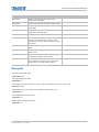
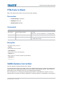
BGF–Base Gamma Function
Defines the gamma power curve to be used when the Gamma table value is set to Gamma Function.
This value, combined with Gamma Slope setting, determines the Gamma table to be used. The
curve is generally a power curve with a small linear segment at the bottom defined by the slope.
Parameters
•
Control Group: Input
•
Subclass: Power Up
•
Access Level: Operator
Commands
Command
Description
Values
BGF+INxy
Sets the base gamma curve for slot x, input
y.
100 to 300
BGF+MAIN
BGF+PIIP
BGF+SECD
where 100 is 1.0 linear and 300 is a 3.00
Sets the base gamma curve for main video. power curve
Sets the base gamma curve for picture-inpicture or secondary video.
M Series Serial API Commands Technical Reference
020-100224-10 Rev. 1 (01-2015)
33
M Series Serial API Commands
Examples
Set the base Gamma Function to 1.0 for main video.
(BGF 100)
Set the base Gamma Function to 3.0 for main video.
(BGF+MAIN 300)
Set the base gamma function to 2.22 for slot 3, input 2.
(BGF+IN32 222)
BGS–Base Gamma Slope
Defines the slope to be used for the base custom Gamma table in the small linear section at the
bottom of the curve. This slope can be used to bring the low level blacks in the image in or out. This
slope, combined with the Gamma function, defines the custom Gamma table.
Parameters
•
Control Group: Input
•
Subclass: Power Up
•
Access Level: Operator
Commands
Command
Description
BGS+INxy
Sets the base gamma curve for slot x, input y.
50 to 200
BGS+MAIN
Sets the base gamma curve for main video.
where 50 is a slope of 0.5 and 200 is a
slope of 2.00
BGS+PIIP
Sets the base gamma curve for picture-in-picture
or secondary video.
BGS+SECD
Values
Examples
Set the base gamma slope to 1.0 for main video.
(BGS 100)
Set the base gamma slope to 2.0 for main video.
(BGS+MAIN 200)
Set the base gamma slope to 1.5 for slot 3, input 2.
(BGS+IN32 150)
M Series Serial API Commands Technical Reference
020-100224-10 Rev. 1 (01-2015)
34
M Series Serial API Commands
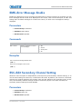
BKY–Broadcast Key Mode
Toggles Broadcast Key mode to select whether all key presses received by the projector are relayed
to all other projectors on the network.
Parameters
•
Control Group: Preference
•
Subclass: Power Down
•
Access Level: Operator
Commands
Command
Description
Values
BKL <0 | 1>
Enables or disables the broadcast key mode.
0 = Disables the broadcast key mode
1 = Enables the broadcast key mode
Examples
Get current Broadcast key state.
(BKY?)
Enable Broadcast Key.
(BKY 1)
Disable Broadcast Key.
(BKY 0)
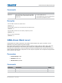
BLB–Blue Black Level
Compensates for relative variations in the black levels between Red, Green and Blue. This is
available on all cards expect the Video decoder.
The correct setting achieves maximum contrast without crushing white or black. When the drive
and black level controls are set correctly for a signal, the Comprehensive Color Adjustment,
including color temperature, works as expected. Do not use the drive and black level controls
Parameters
•
Control Group: Input
•
Subclass: Power Up
•
Access Level: Operator
M Series Serial API Commands Technical Reference
020-100224-10 Rev. 1 (01-2015)
35
M Series Serial API Commands
Commands
Command
Description
Values
BLB+INxy
Sets the blue black level on slot x, input y to the specified value.
-225 to 255
BLB+MAIN
Sets the blue black level on the main video to the specified value.
-225 to 255
BLB+PIIP
Sets the blue black level on the picture-in-picture or secondary video to the
specified value.
-225 to 255
BLB+SECD
Examples
Set blue black level to 128 on main video.
(BLB 128)
Set blue black level to 128 on main video.
(BLB+MAIN 128)
Set blue black level to 100 on PIP video.
(BLB+PIIP 100)
Set blue black level to 100 on slot 3 input 2.
(BLB+IN32 100)
Returns the current blue black level value on main video.
(BLB?)
Returns the current blue black level value on PIP video.
(BLB+PIIP ?)
Returns the current blue black level value on slot 1 input 2.
(BLB+IN12 ?)
BLD–Blue Drive
Compensates for different amounts of attenuation between the Red, Green and Blue in the signal.
This is available on all cards expect the Video decoder.
The correct setting achieves maximum contrast without crushing white or black. When the drive
and black level controls are set correctly for a signal, the Comprehensive Color Adjustment,
including color temperature, works as expected. Do not use the drive and black level controls to
setup a specific color temperature as this requires separate color temperature adjustments to be
made for each source.
Parameters
•
Control Group: Input
•
Subclass: Power Up
•
Access Level: Operator
M Series Serial API Commands Technical Reference
020-100224-10 Rev. 1 (01-2015)
36
M Series Serial API Commands
Commands
Command
Description
Values
BLD+INxy
Sets the blue drive on slot x, input y to the specified value.
-225 to 255
BLD+MAIN
Sets the blue drive on the main video to the specified value.
-225 to 255
BLD+PIIP
Sets the blue drive on the picture-in-picture or secondary video to the
specified value.
-225 to 255
BLD+SECD
Examples
Set blue drive to 128 on main video.
(BLD 128)
Set blue drive to 128 on main video.
(BLD+MAIN 128)
Set blue drive to 100 on PIP video.
(BLD+PIIP 100)
Set blue drive to 100 on slot 3 input 2.
(BLD+IN32 100)
Return the current blue drive value on PIP video.
(BLD+PIIP ?)
Return the current blue drive value on PIP video.
(BLD+PIIP ?)
Return the current blue drive value on PIP video.
(BLD+PIIP ?)
Return the current blue drive value on slot 1 input 2.
(BLD+IN12 ?)
BOG–Blue Odd Pixel Gain
Adds an offset to input blue gain settings on the analog input card, used to compensate for
differences between the A to D converter used to sample even pixels, and the one used for odd
pixels. A value of 0 is the null position in which both A to D converters are set to exactly the same
value.
Parameters
•
Control Group: Option
•
Subclass: Power Up
•
Access Level: Operator
M Series Serial API Commands Technical Reference
020-100224-10 Rev. 1 (01-2015)
37
M Series Serial API Commands
Commands
Command
Description
Values
BOG+SLx0
Sets the blue gain offset for the second A to D.
-
Examples
Set a blue gain offset to -10 on slot 1.
(BOG+SL10 -10)
BOO–Blue Odd Pixel Offset
Adds an offset to input blue black level settings on the analog input card, used to compensate for
differences between the A to D converter used to sample even pixels, and the one used for odd
pixels. A value of 0 is the null position in which both A to D converters are set to exactly the same
value.
Parameters
•
Control Group: Option
•
Subclass: Power Up
•
Access Level: Operator
Commands
Command
Description
Values
BOO+SLx0
Sets the blue black level offset for the second A to D.
-
Examples
Set a blue black level offset to -10 on slot 1.
(BOO+SL10 -10)
BRT–Brightness
Adjusts the offset applied to the input signal.
It has exactly the same effect as adjusting the input levels, except that it operates an all three
colors and can be used to make quick adjustments. For precise control, the input level adjustments
should be used. If the setting is too high, black portions of the image are displayed as dark grey,
M Series Serial API Commands Technical Reference
020-100224-10 Rev. 1 (01-2015)
38
M Series Serial API Commands
making the image appear washed-out. If the setting is too low, dark greys are displayed as deep
black and detail is lost in the darkest parts of the image. This condition is known as crushing. When
adjusting, start from a lower setting and adjust upwards until just above the point where black is
crushed.
Parameters
•
Control Group: Input
•
Subclass: Power Up
•
Access Level: Operator
Commands
Command
Description
Values
BRT+INxy
Sets the brightness on slot x, input y to the specified value.
-1000 to 1000
BRT+MAIN
Sets the brightness on the main video t the specified value.
-1000 to 1000
BRT+PIIP
Sets the brightness on the picture-in-picture or secondary video to the
specified value.
-1000 to 1000
BRT+SECD
Examples
Set brightness to 500 on main video.
(BRT 500)
Set brightness to 500 on main video.
(BRT+MAIN 500)
Set brightness to -250 on PIP video.
(BRT+PIIP -250)
Set brightness to 100 on slot 3 input 2.
(BRT+IN32 100)
Return the current brightness value on main video.
(BRT?)
Return the current brightness value on PIP video.
(BRT+PIIP ?)
Return the current brightness value on slot 1 input 2.
(BRT+IN12 ?)
M Series Serial API Commands Technical Reference
020-100224-10 Rev. 1 (01-2015)
39
M Series Serial API Commands
BRU–Brightness Uniformity
Enables or disables brightness uniformity and adjusts brightness uniformity output based on the
current lamp mode.
Parameters
•
Control Group: Preference
•
Subclass: Power Down
•
Access Level: Operator
Commands
Command
Description
Values
BRU+SLCT
Enables or disables brightness uniformity.
0 = Disables brightness
uniformity
1 = Enables brightness
uniformity
BRU+CRSA
Enables or disables the BRU coarse adjustment.
0 = Disables the BRU coarse
adjustment
1 = Enables the BRU coarse
adjustment
BRU+UITL
Gets or sets the percent of gain at the top left corner.
-
BRU+UIML
Gets or sets the percent of gain at the left side.
-
BRU+UIBL
Gets or sets the percent of gain at the bottom left corner.
-
BRU+UITR
Gets or sets the percent of gain at the top right corner.
-
BRU+UIMR
Gets or sets the percent of gain at the right side.
-
BRU+UIBR
Gets or sets the percent of gain at the bottom right corner.
-
BRU+UIH1
Gets or sets the percent of gain at the left turn point.
-
BRU+UIH2
Gets or sets the percent of gain at the right turn point.
-
BRU+UI1P
Gets or sets the position of the left turn point.
-
BRU+UI2P
Gets or set the position of the right turn point.
-
BRU+GAIN
Gets or sets the overall gain.
-
BRU+UIRT
Restores all parameters to the factory default for the current lamp.
1
Examples
Get current state of brightness uniformity, 0 is disabled, 1 is enabled.
(BRU+SLCT ?)
M Series Serial API Commands Technical Reference
020-100224-10 Rev. 1 (01-2015)
40
M Series Serial API Commands
Enable brightness uniformity.
(BRU+SLCT 1)
Check if Coarse Adjustment is enabled or not.
(BRU+CRSA ?)
Enable the Coarse Adjustment mode.
(BRU+CRSA 1)
Get current gain at top left corner.
(BRU+UITL ?)
Set gain at top left corner to 0.8.
(BRU+UITL 80)
Get current gain at left edge.
(BRU+UIML ?)
Set gain at left edge to 1.0.
(BRU+UIML 100)
Get current gain at bottom left corner.
(BRU+UIBL ?)
Set gain at bottom left corner to 0.8.
(BRU+UIBL 80)
Get current gain at top right corner.
(BRU+UITR ?)
Set gain at top right corner to 0.8.
(BRU+UITR 80)
Get current gain at right edge.
(BRU+UIMR ?)
Set gain at right edge to 0.8.
(BRU+UIMR 80)
Get current gain at bottom right corner.
(BRU+UIBR ?)
Set gain at bottom right corner to 0.8.
(BRU+UIBR 80)
Get current gain at left turn point.
(BRU+UIH1 ?)
Set gain at left turn point to 0.8.
(BRU+UIH1 80)
Get current gain at right turn point.
(BRU+UIH2 ?)
Set gain at right turn point to 0.8.
(BRU+UIH2 80)
M Series Serial API Commands Technical Reference
020-100224-10 Rev. 1 (01-2015)
41
M Series Serial API Commands
Get current position of left turn point.
(BRU+UI1P ?)
Locate left turn point pixel 375 from the left edge.
(BRU+UI1P 375)
Get current position of right turn point.
(BRU+UI2P ?)
Locate right turn point pixel 900 from the left edge.
(BRU+UI2P 900)
Reset all BRU parameters for current lamp mode.
(BRU+UIRT 1)
Get current overall gain.
(BRU+GAIN ?)
Set overall gain to 1.000.
(BRU+GAIN 1000)
CCD–Output Color Default
Specifies the default color adjustment to use for new channels. The user can specify a standard
color and have that color applied by default to all new sources. The user can override this for any
specific channel. Using the default subcode applies a default to be used when creating a new
channel using auto setup while the filter (either the Yellow Notch Filter or the Color Purity Filter) is
not in the video path. Using the subcode DYNF allows a different color table default to be specified
while the YNF/CPF is in the video path during auto setup.
Parameters
•
Control Group: Preference
•
Subclass: Power Up
•
Access Level: Operator
Commands
Command
Description
Values
CCD <value>
Applies a default table to use while running auto setup when a YNF/CPF filter is
not in place.
-
CCD+DYNF
Applies a default table to use while running auto setup when a YNF/CPF filter is
in place.
-
M Series Serial API Commands Technical Reference
020-100224-10 Rev. 1 (01-2015)
42
M Series Serial API Commands
Examples
Make new channels using the MAX drive table, while running auto setup and YNF is out.
(CCD 0)
Make new channels using the HD table, while running auto setup and YNF is in.
(CCD+DYNF 4)
CCI–Interpolated Color
Generates an output color map based on interpolating the values for the standard color
temperatures. You can adjust the color temperature of the image. The selected output color table
must be on Color Temperature to enable this control.
Parameters
•
Control Group: Input
•
Subclass: Power Up
•
Access Level: Operator
Commands
Command
Description
Values
CCI+INxy
Sets the interpolated color temperature for slot x, input y.
3200K to 9300K
CCI+MAIN
Sets the interpolated color temperature for the main video.
3200K to 9300K
CCI+PIIP
Sets the interpolated color temperature for picture-in-picture or
secondary video.
3200K to 9300K
CCI+SECD
Examples
Set the interpolated color temperature to 9300K for main video.
(CCI 9300)
CCS–Select Output Color
Selects which of several predefined and four user-defined color maps to use for a specific input
signal.
M Series Serial API Commands Technical Reference
020-100224-10 Rev. 1 (01-2015)
43
M Series Serial API Commands
Parameters
•
Control Group: Input
•
Subclass: Power Up
•
Access Level: Operator
Commands
Command
Description
Values
CCS+INxy
Selects the color temperature
for slot x, input y.
0 = MaxDrives—Turns off all color adjustments allowing the
projector to run at maximum brightness.
CCS+MAIN
Selects the color temperature
for the main video.
CCS+PIP
Selects the color temperature
for picture-in-picture or
secondary video.
2 = Color Temperature—Specifies a color temperature
between 3200 and 9300 based on the setting of the Color
Temperature control. Color temperature is expressed in
degrees Kelvin [3200, 5400, and so on]. Lower numbers give
a reddish white, higher numbers appear bluish. There are four
standard settings:
CCS+SECD
• 9300K—Close to the white of many computer monitors.
• 6500K—Standard for color video, in both standard and high
definition forms.
• 5400K—Standard for graphics and black-and-white video.
• 3200K—Useful if the projected image is to be filmed or shot
as part of a studio set illuminated with incandescent lights.
For all color temperatures, the color primaries (red, green
and blue) are unchanged and reflect the native colors of
the projector.
3 = SD Video—Adjusts the color of red, green and blue, as
well as the color of white. Optimized for SD video.
4 = HD Video—Adjusts the color of red, green and blue, as
well as the color of white. Optimized for HD video.
5 = User 1—Selects a user defined set of color adjustments.
6 = User 2—Selects a user defined set of color adjustments.
7 = User 3—Selects a user defined set of color adjustments.
8 = User 4—Selects a user defined set of color adjustments.
The set of four user defined settings are defined in the
Configuration menu.
Examples
Set the color temp setting to max drives for main video.
(CCS 0)
CHA–Channel
Changes the current channel.
M Series Serial API Commands Technical Reference
020-100224-10 Rev. 1 (01-2015)
44
M Series Serial API Commands
Switching channels switches to the appropriate option card/input. If the signal signature in the
channel does not match the signal on the channel's input, the channel change switches to the autochannel or to the channel that was defined for the signal signature that is on the channel's input.
This command fails if the data in the channel file does not match the current system hardware. Use
this command to copy, delete, and edit certain channel properties.
Parameters
•
Control Group: Unsaved
•
Subclass: Power Up
•
Access Level: Operator
Commands
Command
Description
Values
CHA+COPY
Makes a copy of a channel and assigns it a unique number
(optionally, specifies a new channel number).
1 to 99
CHA+DLET
Deletes a channel.
1 to 99
CHA+MAIN
Sets the channel being used by main video.
1 to 99
CHA+PIIP
Sets the channel being used by picture-in-picture or the
secondary video.
1 to 99
Displays the information on the current channel.
1 to 99
CHA+SECD
CHA+INFO
Examples
Select a Four-Port input configuration using slots 1 and 2.
(CHA 1)
Get current active channel.
(CHA?)
Set main to channel 10.
(CHA 10)
Set picture-in-picture to channel 99.
(CHA+PIIP 99)
Make a copy of channel 1, using the next free channel number.
(CHA+COPY 1)
Make a copy of channel 1, and copy to channel 20 (fails if 20 already exists).
(CHA+COPY 1 20)
Delete all unlocked channels.
(CHA+DLET 0)
M Series Serial API Commands Technical Reference
020-100224-10 Rev. 1 (01-2015)
45
M Series Serial API Commands
Delete channel 20.
(CHA+DLET 20)
CLE–Color Enable
Allows the three primary colors (red, green, and blue) to be turned on or off separately. Use this
command to look at the colors one at a time or in pairs when doing convergence, light
measurements, and so on.
Parameters
•
Control Group: Unsaved
•
Subclass: Power Up
•
Access Level: Operator
Commands
Command
Description
CLE <color>
Enables specific colors in the video path.
Values
0 = White (all colors on)
1 = Red
2 = Green
3 = Blue
4 = Yellow (red and green on)
5 = Cyan (green and blue on)
6 = Magenta (red and blue on)
Examples
Display red portion of image only.
(CLE 1)
Display green and blue portion of image only.
(CLE 5)
Display image normally (all primaries).
(CLE 0)
CLP–Clamping
Generates a clamping pulse for all analog signals that defines where in the signal a black reference
can be found.
M Series Serial API Commands Technical Reference
020-100224-10 Rev. 1 (01-2015)
46
M Series Serial API Commands
The Clamp Location sets the clamping pulse to one of three possible locations: tip, back porch, and
tri-level. For most signals the correct position is back porch, just after the sync pulse. If the signal
has no back porch and no sync pulse in the RG or B signals, clamping can occur at the front or tip
of the sync pulse.
For HDTV signals [1080i & 720p] the clamp must be moved past the positive pulse of the tri-level
sync pulse, so the tri-level option is correct. For almost all other signals, backporch is correct. Sync
tip is needed only if the back porch is too small. For many signals, this control has no effect.
Change this setting only if the image appears unusually dim, has horizontal streaks, or shows
significant color drift.
Parameters
•
Control Group: Input
•
Subclass: Power Up
•
Access Level: Operator
Commands
Command
Description
Values
CLP+INxy
Sets the black level clamping for slot x, input y.
0 = Back porch
CLP+MAIN
Sets the black level clamping for the main video.
1 = Sync tip
CLP+PIIP
Sets the black level clamping for picture-in-picture or secondary video.
2 = Tri-level
CLP+SECD
Examples
Set the black level clamping for main video to sync tip.
(CLP 1)
Set the black level clamping for main video to sync tip.
(CLP+MAIN 1)
Set the black level clamping for slot 3 input 2 to sync tip.
(CLP+IN32 1)
CLR–Color
Adjusts the saturation (amount) of color in a video image.
Parameters
•
Control Group: Input
M Series Serial API Commands Technical Reference
020-100224-10 Rev. 1 (01-2015)
47
M Series Serial API Commands
•
Subclass: Power Up
•
Access Level: Operator
Commands
Command
Description
Values
CLR+INxy
Sets the color saturation for slot x, input y.
0 to 1000
CLR+MAIN
Sets the color saturation for the main video.
0 to 1000
CLR+PIIP
Sets the color saturation for picture-in-picture or secondary video.
0 to 1000
CLR+SECD
Examples
Set color saturation to 500 on main video.
(CLR 500)
Set color saturation to 500 on main video.
(CLR MAIN 500)
Set color saturation to 250 on PIP video.
(CLR PIIP 250)
Set color saturation to 100 on slot 3 input 2.
(CLR IN32 100)
Return the current color saturation value on main video.
(CLR ?)
Return the current color saturation value on PIP video.
(CLR PIIP ?)
Return the current color saturation value on slot 1 input 2.
(CLR IN12 ?)
CON–Contrast
Sets the image contrast by adjusting the gain applied to the input signal.
This command has the same effect as adjusting the input levels, except that it operates an all three
colors and can be used to make quick adjustments. For precise control, the input level adjustments
must be used. If the setting is too high, bright portions of the image not quite at peak white are
displayed as peak white and detail is lost in the brightest parts of the image. This condition is
known as crushing. If the setting is too low, the image is dimmer than it needs be. Start from a
lower setting and adjust upwards until just below the point where white is crushed.
M Series Serial API Commands Technical Reference
020-100224-10 Rev. 1 (01-2015)
48
M Series Serial API Commands
Parameters
•
Control Group: Input
•
Subclass: Power Up
•
Access Level: Operator
Commands
Command
Description
Values
CON+INxy
Sets the contrast for slot x, input y.
0 to 1000
CON+MAIN
Sets the contrast for the main video.
0 to 1000
CON+PIIP
Sets the contrast for picture-in-picture or secondary video.
0 to 1000
CON+SECD
Examples
Set contrast to 500 on main video.
(CON 500)
Set contrast to 500 on main video.
(CON MAIN 500)
Set contrast to 250 on PIP video.
(CON PIIP 250)
Set contrast to 100 on slot 3 input 2.
(CON IN32 100)
Return the current contrast value on main video.
(CON ?)
Return the current contrast value on PIP video.
(CON PIP ?)
Return the current contrast value on slot 1 input 2.
(CON IN12 ?)
CRM–Chroma/Luma Delay
Adjusts the time delay between the chroma and the luminance signals in decoded signals. Adjust
the delay to eliminate shadows occurring with adjacent colors. It is only useful for video images
processed by decoder cards.
M Series Serial API Commands Technical Reference
020-100224-10 Rev. 1 (01-2015)
49
M Series Serial API Commands
Parameters
•
Control Group: Input
•
Subclass: Power Up
•
Access Level: Operator
Commands
Command
Description
Values
CRM+INxy
Sets the luma delay for slot x, input y.
-3 to 3 pixels
CRM+MAIN
Sets the luma delay for the main video.
-3 to 3 pixels
CRM+PIIP
Sets the luma delay for picture-in-picture or secondary video.
-3 to 3 pixels
CRM+SECD
Examples
Set luma delay to 3 pixel on main video.
(CRM 3)
Set luma delay to 3 pixel on main video.
(CRM MAIN 3)
Set luma delay to 3 pixel on PIP video.
(CRM PIIP 3)
Set luma delay to -3 pixel on slot 3 input 2.
(CRM IN32 -3)
Returns the current luma delay on main video.
(CRM ?)
Returns the current luma delay on PIP video.
(CRM PIIP ?)
Returns the current luma delay on slot 1 input 2.
(CRM IN12 ?)
CSP–Color Space Selection
Specifies which color space the input signal uses.
This determines how the color components are decoded for accurate color in the display. Color
space control only applies to analog input signals. Although the proper color space is normally
determined automatically by the projector, you can override the setting. Use RGB unless you are
M Series Serial API Commands Technical Reference
020-100224-10 Rev. 1 (01-2015)
50
M Series Serial API Commands
using component video. Use YPbPr(SDTV) for most video sources. Use YPbPr(HDTV) for high
definition signals.
When certain RGB signals are first connected, the projector may not initially recognize them
as RGB and may incorrectly decode their color information as YPbPr(SDTV). These signals
can include: RGB signals in NTSC, PAL, SECAM frequency ranges, Scan-doubled sync-ongreen, Scan-quadrupled sync-on-green. For these signals, change the Color Space
i
to RGB, then define a new channel for future use.
Parameters
•
Control Group: Input
•
Subclass: Power Up
•
Access Level: Operator
Commands
Command
Description
Values
CSP+INxy
Sets the color space on slot x, input y.
0 = RGB
CSP+MAIN
Sets the color space on the main video.
1 = YPbPr (SDTV)
CSP+PIIP
Sets the color space on picture-in-picture
or secondary vide.
CSP+SECD
2 = YPbPr (HDTV)
Examples
Set color space to YPbPr(SDTV) on main video.
(CSP 1)
Set color space to YPbPr(HDTV) on main video.
(CSP+MAIN 2)
Set color space to YPbPr(SDTV) on PIP video.
(CSP+PIIP 1)
Set color space to YPbPr(SDTV) on slot 3 input 2.
(CSP+IN32 1)
Returnsthe current color space value on main video.
(CSP?)
Return the current color space value on PIP video.
(CSP+PIIP?)
Return the current color space value on slot 1 input 2.
(CSP+IN12?)
M Series Serial API Commands Technical Reference
020-100224-10 Rev. 1 (01-2015)
51
M Series Serial API Commands
DED–Dual DVI EDID Type Selection
Sets the preferred EDID Timings on the Dual DVI input card.
Parameters
•
Control Group: Option
•
Subclass: Power Up
•
Access Level: Operator
Commands
Command
Description
DED+SLxy
Sets the EDID timings for slot to the specified type.
Values
0 = Default
1 = 3D
2 = Custom
Examples
Set EDID type to 1 (3D) on slot 3 input 1.
(DED+SL31 1)
Return the current EDID type on slot 1 input 2.
(DED+SL12 ?)
DEF–Factory Defaults
Resets all preference and configuration settings to their default values. To prevent accidental use of
this command, the number 111 must follow the command.
Parameters
•
Control Group: Unsaved
•
Subclass: Power Down
•
Access Level: Admin
M Series Serial API Commands Technical Reference
020-100224-10 Rev. 1 (01-2015)
52
M Series Serial API Commands
Commands
Command
Description
Values
DEF 111
Performs the factory default command.
111—Must be entered exactly as is
Examples
Reset the projector to factory defaults.
(DEF 111)
(65535 00000 FYI00919 “All settings have been restored to their factory defaults.
Reboot is required to take effect.”)
DEQ–DDIC Equalization Level
Sets the DDIC equalization level.
Parameters
•
Control Group: Option
•
Subclass: Power Up
•
Access Level: Admin
Commands
Command
Description
Values
DEQ+SLx0
Sets the equalization level on slot x to the
specified level.
0 = Auto
1 = High (suitable when using longer DVI cables)
2 = Low (suitable when using shorter DVI cables
Examples
Set equalization level to 2 (Low) on slot 3.
(DEQ+SL30 2)
Return the current equalization level on slot 1.
(DEQ+SL10 ?)
M Series Serial API Commands Technical Reference
020-100224-10 Rev. 1 (01-2015)
53
M Series Serial API Commands
DIM–Dynamic Iris Mode
Sets the dynamic iris mode for the current channel. The IRS control must be set to Per Channel
mode before this control can be enabled.
Parameters
•
Control Group: Input
•
Subclass: Power Up
•
Access Level: Operator
Commands
Command
Description
Values
DIM <value>
Selects the dynamic iris mode.
0 = Off—Turns the dynamic iris off for this channel
1 = Manual—Places the dynamic iris in Manual mode for this
channel
2 = Dynamic—Places the dynamic iris in Dynamic mode for
this channel
Examples
Set the dynamic iris for the current channel to Dynamic mode.
(DIM 2)
DIS–Dynamic Iris Settings
Selects which of several predefined and four user defined iris strength maps to use for a specific
input signal.
Parameters
•
Control Group: Input
•
Subclass: Power Up
•
Access Level: Operator
M Series Serial API Commands Technical Reference
020-100224-10 Rev. 1 (01-2015)
54
M Series Serial API Commands
Commands
Command
Description
Values
DIM <value>
Selects the dynamic iris
strength.
0 = Dark Scenes—Selects aggressive settings for high contrast
adjustment, ideal for movies with lots of dark scenes, such as
horror, thriller.
1 = Medium Scenes—Selects moderate contrast adjustment,
ideal for video with some dark scenes, such as action.
2 = Light Scenes—Selects minimum contrast adjustment, ideal
for video with only a few dark scenes, animation, or graphic
input, such as a PC.
3 = User 1—Selects a user defined set to dynamic iris settings.
4 = User 2—Selects a user defined set to dynamic iris settings.
5 = User 3—Selects a user defined set to dynamic iris settings.
6 = User 4—Selects a user defined set to dynamic iris settings.
Examples
Set the iris for a high contrast ratio, such as input with lots of dark scenes.
(DIS 0)
DLG–Data Logging
Sets data logging level.
Parameters
•
Control Group: Preference
•
Subclass: Power Down
•
Access Level: Operator
Commands
Command
Description
Values
DLG <value>
Selects the data logging level.
0 = Minimal logging of activities—Logging system errors,
warnings and events, for example power on/off, lamp on/off,
user login/logout.
1 = Normal logging—Most activities logged such as errors,
warnings, events, and other info.
2 = Debug logging—All activities are logged.
M Series Serial API Commands Technical Reference
020-100224-10 Rev. 1 (01-2015)
55
M Series Serial API Commands
Examples
Get current logging level.
(DLG?)
(DLG!001)
Set current logging level to 1.
(DLG 1)
DMX–DMX/ArtNet
Sets options for the DMX interface. A user can select whether they want to receive data from both
the DMX input card (inserted into the card cage in one of the input slots), or using ArtNet, an
Ethernet based DMX protocol which monitors UDP port 6454.
The Input termination (2 Watt, 120 Ohm) is required on the last DMXC card in a loop through
configuration. (such as only on the last projector). Termination may be either hardware (by
plugging in a termination dongle, and so on) or may be switched in by software, but should not be
both.
Christie recommends hardware termination because software termination is only in place when the
projector has AC applied. If the network must be terminated without AC applied to the last
projector, use a hardware terminator.
Parameters
•
Control Group: Preference
•
Subclass: Power Up
•
Access Level: Operator
Commands
Command
Description
Values
DMX <value>
Selects the source of the DMX/ArtNet input.
0 = DMX Input Card and ArtNet—
Monitors for data on both the DMX input
card (if plugged in) and ArtNet. If the
DMX card is actively receiving data,
ArtNet is ignored.
1 = DMX Input Card Only—Monitors only
the DMX card for input.
2 = ArtNet Only—Monitors only ArtNet
for input.
3 = Disabled—Disables both interfaces.
M Series Serial API Commands Technical Reference
020-100224-10 Rev. 1 (01-2015)
56
M Series Serial API Commands
Command
Description
Values
DMX+CHAN
Sets the base channel for the DMX device. Generally
used if multiple projectors are on a single subnet/
universe such as the first projector would use base
channel 0. If using the basic personality (20
channels),
-
the second projector should use base channel 21. The
DMX specification supports overlap but Christie does
not recommend this.
Note: The base channel setting must allow enough
space for the channels required by the selected
personality, such as if the basic personality is selected,
the base channel may be in the range 1-492. If the
advanced personality is selected, the base channel
may be in the range 1-448.
DMX+PERS
Sets the DMX personality. A personality represents a
set of channels the application monitors for changes.
0 = Show—A minimal personality
composed of controls most likely to be
used while a show is running
1 = Setup—Contains all of the show
controls plus additional controls used for
setting up a show
2 = Zap—Special personality which uses
locks for critical functions (cannot be
used with an all-slider type board.
DMX+TERM
Switches termination resistance in/out of the circuit. If
software termination is used on the DMX input card,
enable this control. If not enabled, use a physical
terminator. You may need to clear this setting upon
card removal. By default SW termination is disabled.
-
DMX+UNVS
Specifies which universe the projector belongs to, so it
can filter out all other data packets. The Universe
applies to ArtNet only and does not apply to the DMXC
input card.
-
DMX+SUBN
Sets the subnet for this projector. This is not to be
confused with a subnet mask. A subnet identifies a set
of universes. The subnet and universe in combination
uniquely identify the channels a projector is listening
on. The Subnet applies to ArtNet only and does not
apply to the DMXC input card.
-
DMX+FLTR
If you have a noisy Analog to Digital converter in your
DMX/ArtNet device (output oscillates between two
values), this filter can be used to eliminate the input
noise at the cost of fine control resolution in some
controls.
0 = Default
Christie does not recommend using this feature unless
you experience problems with your DMX input.
Examples
Ignore ArtNet traffic, use only the DMX interface.
(DMX1)
M Series Serial API Commands Technical Reference
020-100224-10 Rev. 1 (01-2015)
57
M Series Serial API Commands
Set the base channel to 50 (such as listen to data starting at channel 50).
(DMX+CHAN 50)
DRK–3D Dark Interval
Controls the time between frames when no image is being projected to the screen. Used for 3D
applications to determine the time that the shutter mechanism has to open or close between fields.
Keep at default value of zero for all other applications. Increasing this control reduces the peak
brightness of the image.
Parameters
•
Control Group: Input
•
Subclass: Power Up
•
Access Level: Operator
Commands
Command
Description
Values
DRK+MAIN
Sets the 3D dark interval for the main image
-
DRK+INxy
Set the 3D dark interval for slot x, input y.
-
Examples
Set 3D dark interval to 0 on main video.
(DRK 0)
Set 3D dark interval to 5.00 milliseconds on main.
(DRK+MAIN 500)
Set 3D dark interval to 3.00 milliseconds on slot 1 input 2.
(DRK+IN12 300)
Returns the 3D dark interval value on main video.
(DRK?)
Returns the 3D dark interval on slot 1 input 2.
(DRK+IN12?)
M Series Serial API Commands Technical Reference
020-100224-10 Rev. 1 (01-2015)
58
M Series Serial API Commands
DTL–Detail
Adjusts the sharpness of the image. The sharpness detail enhancement applied is based on
adaptive horizontal, vertical, and diagonal large edge and small edge enhancement processes.
Setting detail above the halfway-point can introduce noise in the image; lower settings can improve
a noisy signal. This command does not take effect unless the minimum change required in the
(DTT) control is reached.
Parameters
•
Control Group: Input
•
Subclass: Power Up
•
Access Level: Operator
Commands
Command
Description
Values
DTL+INxy
Sets the detail for slot x, input y.
-
DTL+MAIN
Sets the detail for the main video.
-
DTL+PIIP
Sets the detail for picture-in-in-picture or
the secondary video.
-
DTL+SECD
Examples
Set the detail to mid-point for the main video.
(DTL 50)
DTO–Detail Overshoot
Minimizes ringing on the enhanced edges detail and texture effects.
Parameters
•
Control Group: Input
•
Subclass: Power Up
•
Access Level: Operator
M Series Serial API Commands Technical Reference
020-100224-10 Rev. 1 (01-2015)
59
M Series Serial API Commands
Commands
Command
Description
Values
DTO+INxy
Sets the detail overshoot for slot x, input y.
-
DTO+MAIN
Sets the detail overshoot for the main video.
-
DTO+PIIP
Sets the detail overshoot for picture-in-picture or the secondary video
-
DTO+SECD
Examples
Set the detail overshoot to mid point for the main video.
(DTO 50)
DTT–Detail Threshold
Selects a filter sensitivity to noise. A higher value may improve noisy sources especially for higher
settings of detail.
Sets the minimum change required before the detail (DTL) function is activated. Images can be
sharpened without increasing the background noise.
Parameters
•
Control Group: Input
•
Subclass: Power Up
•
Access Level: Operator
Commands
Command
Description
Values
DTT+INxy
Sets the detail threshold for slot x, input y.
-
DTT+MAIN
Sets the detail threshold for the main video.
-
DTT+PIIP
Sets the detail threshold for picture-in-picture or the secondary video
-
DTT+SECD
Examples
Set the detail threshold to mid point for the main video.
(DTT 50)
M Series Serial API Commands Technical Reference
020-100224-10 Rev. 1 (01-2015)
60
M Series Serial API Commands
EBB–Black Level Blending
Selects the black level blend to use on the projector.
Black Level Blending is the process of modifying the pixels in the bright overlapping areas that
result from the overlapping of two or more images. Correct adjustment eliminates uneven black
levels by matching up black area hues with a target area hue (the intersection of the center lines),
and adjusting the overlaps (edges) surrounding the target area. Use the black test pattern to
perform this function.
Parameters
•
Control Group: Configuration
•
Subclass: Preference
•
Access Level: Operator
Commands
Command
Description
Values
EBB+SLCT
Enables or disables black edge blending mode or chooses a
saved Twist black level blending present.
0 = Disables black edge
blending
1 = Enables black edge
blending
EBB+CNTV
Changes edge blending black level in the center zone.
-
EBB+TOPV
Changes edge blending black level in the top zone.
-
EBB+LFTV
Changes edge blending black level in the left zone.
-
EBB+RHTV
Changes edge blending black level in the right zone.
-
EBB+BTMV
Changes edge blending black level in the bottom zone.
-
EBB+TLTV
Changes edge blending black level in the top left zone.
-
EBB+TRTV
Changes edge blending black level in the top right zone.
-
EBB+BLTV
Changes edge blending black level in the bottom left zone.
-
EBB+BRTV
Changes edge blending black level in the bottom right zone.
-
EBB+LFTW
Changes edge blending black level width of the left zone.
-
EBB+RHTW
Changes edge blending black level width of the right zone.
-
EBB+TOPW
Changes edge blending black level width of the top zone.
-
EBB+BTMW
Changes edge blending black level width of the bottom
zone.
-
EBB+RSTD
Resets all black level blending parameters to the default
values.
-
M Series Serial API Commands Technical Reference
020-100224-10 Rev. 1 (01-2015)
61
M Series Serial API Commands
Examples
Set black level blend offset of center zone to 100.
(EBB+CNTV 100)
Set black level blend width of left zone to 200.
(EBB+LFTW 200)
Get black level blend width of right zone
(EBB+RHTW?)
EBL–Edge Blending
Controls edge blending settings so that any of the four edges can be blended with an adjacent
projector to achieve an overlapped and seamless image.
Parameters
•
Control Group: Configuration/Preference
•
Subclass: Power Up
•
Access Level: Operator
Commands
Command
Description
Values
EBL+SLCT
Enables or disables standard edge blending mode,
or choose a saved Twist blending preset.
0 = Disables standard edge blending
mode
1 = Enables standard edge blending
mode
EBL+LFTW
Changes edge blending width of the left edge.
-
EBL+LFTM
Changes edge blending curve midpoint of the left
edge.
-
EBL+LFTS
Changes edge blending curve slope at the
midpoint on the left edge.
-
EBL+RHTW
Changes edge blending width of the right edge.
-
EBL+RHTM
Changes edge blending curve midpoint of the
right edge.
-
EBL+RHTS
Changes edge blending curve slope at the
midpoint on the right edge.
-
EBL+TOPW
Changes edge blending width of the top edge.
-
EBL+TOPM
Changes edge blending curve midpoint of the top
edge.
-
M Series Serial API Commands Technical Reference
020-100224-10 Rev. 1 (01-2015)
62
M Series Serial API Commands
Command
Description
Values
EBL+TOPS
Changes edge blending curve slope at the
midpoint on the top edge.
-
EBL+BTMW
Changes edge blending width of the bottom edge.
-
EBL+BTMM
Changes edge blending curve midpoint of the
bottom edge.
-
EBL+BTMS
Changes edge blending curve slope at the
midpoint on the bottom edge.
-
EBL+STDC
Change the standard blending curve.
-
EBL+OVLP
Enables or Disables edge blending overlap control.
This more will make the active portion of the
Blend zone very obvious and is intended to make
setup easier.
-
EBL+RSTA
Reset all edge blending parameters to default
values.
-
EBL+RSTC
Reset all advanced edge blending parameters to
default values.
-
EBL+FILT
Adjust to reduce saccadic eye-motion artifacts,
sometimes noticeable in blend regions.
-
EBL+DTHF
When this control is enabled, the Eye-Motion Filter
will be applied to the entire screen, rather than
applying just to the edge blending regions.
-
Examples
Set edge blending left width.
(EBL+LFTW 100)
Get edge blending left width.
(EBL+LFTW ?)
Set blending top edge slope to be 1.5. Only works with standard curve type 1 (5th order).
(EBL+TOPS 150)
Set blending curve to be a cosine curve. default is a fifth-order curve.
(EBL+STDC 1)
Use standard edge blending mode.
(EBL+SLCT 1)
Enable edge blending overlap mode.
(EBL+OVLP 1)
M Series Serial API Commands Technical Reference
020-100224-10 Rev. 1 (01-2015)
63
M Series Serial API Commands
EME–Error Message Enable
Enables the displaying of error messages and determines to which interface the messages are sent.
Error messages can be turned off or displayed on the screen, sent out the serial port, or both. This
setting does not affect messages for invalid user entries, for which error messages are always
displayed.
Parameters
•
Control Group: Preference
•
Subclass: Power Down
•
Access Level: Operator
Commands
Command
Description
Values
EME <value>
Selects interfaces to receive
error messages.
0 = Off
1 = Screen
2 = Serial ports
3 = All
Examples
Get current Error Message Enable state.
(EME ?)
Direct error messages to the screen.
(EME 1)
ESC–Edit Secondary Channel Setting
Allows the user the option to independently control primary and secondary channel settings, or to
use the same setting for both links, in Interleaved 3D mode. By default, this control is unchecked,
meaning any settings applied to the primary input are also applied to the secondary input. In this
case, the secondary channel settings cannot be set directly by the user. When checked, the
secondary channel settings become editable.
Parameters
•
Control Group: Preference
•
Subclass: Power Up
•
Access Level: Operator
M Series Serial API Commands Technical Reference
020-100224-10 Rev. 1 (01-2015)
64
M Series Serial API Commands
Commands
Command
Description
Values
ESC <value>
Sets primary/second channel independence for Interleave 3D mode.
-
Examples
Enable editing of secondary channel/input settings.
(ESC 1)
FAD–Fade Time
Controls the amount of time it takes to fade between images on a source switch. It also fades in the
picture-in-picture and on-screen display, if possible.
Parameters
•
Control Group: Preference
•
Subclass: Power Down
•
Access Level: Operator
Commands
Command
Description
Values
FAD <value>
Sets the time in hundredths of a second to
allow the fade.
0 to 150
where:
150 = 1.5 seconds
1 = 10 minutes
0 = Off
Examples
Fade out for one second.
(FAD 100)
FAS–Fan Assist Switch
Enables or disables the ability for all fans to operate at maximum speed during a thermal over-temp
condition.
M Series Serial API Commands Technical Reference
020-100224-10 Rev. 1 (01-2015)
65
M Series Serial API Commands
Parameters
•
Control Group: Saved
•
Subclass: Power Down
•
Access Level: Operator
Commands
Command
Description
FAS <0 | 1>
Enables or disables the maximum fan operation.
Values
0 = Disables the maximum fan operation
1 = Enables the maximum fan operation
Examples
Turn on fan assist.
(FAS 1)
Turn off fan assist.
(FAS 0)
FCS–Lens Focus Position Adjustment
Moves the focus motor to a specified position. The range may change after running the Lens
Calibration function, which determines the full range allowed by the hardware.
Parameters
•
Control Group: Configuration
•
Subclass: Power Up
•
Access Level: Operator
Commands
Command
Description
Values
FCS <position>
Adjusts the lens focus to the specified position.
-1200 to 1200
M Series Serial API Commands Technical Reference
020-100224-10 Rev. 1 (01-2015)
66
M Series Serial API Commands
Examples
Move lens focus to position 500.
(FCS 500)
FIL–Filter
Applies an internal Low Pass Filter to the current input signal, before the A/D conversion in analog
cards. This removes high frequency noise from input signals. HDTV is typically used for 720p and
1080i video sources. The high bandwidth filter should be used for 1080p or higher frequency
sources.
Parameters
•
Control Group: Input
•
Subclass: Power Up
•
Access Level: Operator
Commands
Command
Description
Values
FIL+INxy
Sets the filter for slot x, input y.
0 = Off
FIL+MAIN
Sets the filter for the main video.
1 = HDTV-High Bandwidth
FIL+PIIP
Sets the filter for picture-in-picture or the
secondary video.
FIL+SECD
2 = HDTV
3 = EDTV
4 = SDTV
Examples
Set the filter for main video to HDTV.
(FIL 2)
Set the filter for main video to HDTV.
(FIL+MAIN 2)
Set the filter for slot 3 input 2 to HDTV.
(FIL+IN32 2)
M Series Serial API Commands Technical Reference
020-100224-10 Rev. 1 (01-2015)
67
M Series Serial API Commands
FLE–Frame Lock Enable
Enables or disables Frame Lock, which controls how the projector controls the output frame timing
based on the input signal. When set to Frame Lock, output image frames are locked to the input if
possible. When locked, the output is always locked to the primary input, never the PIP image. Free
Run sets the output to close to 60Hz for all sources. This control must be set to locked if a 3Dstereo signal is used.
Parameters
•
Control Group: Preference
•
Subclass: Power Up
•
Access Level: Operator
Commands
Command
Description
FLE <0 | 1>
Enables or disables the frame lock.
Values
0 = Disables the frame lock
1 = Enables the frame lock
Examples
Get frame lock enabled status.
(FLE ?)
Free Run output.
(FLE 0)
Enables frame lock.
(FLE 1)
FLW–Serial Flow Control
Sets the flow control for a serial communications port.
Parameters
•
Control Group: Preference
•
Subclass: Power Down
•
Access Level: Advanced
M Series Serial API Commands Technical Reference
020-100224-10 Rev. 1 (01-2015)
68
M Series Serial API Commands
Commands
Command
Description
Values
FLW+PRTA
Sets the mode on port A. (RS232 In)
-
FLW+PRTB
Sets the mode on port A. (RS232 Out)
-
FLW+PRTC
Sets the mode on port C. (RS422)
-
Examples
Get flow control.
(FLW+PRTA?)
(FLW+PRTA!001 "Software")k
Set no flow control on port A.
(FLW+PRTA “NONE”)
Set flow control on port A to software.
(FLW+PRTA “SOFTWARE”)
FMD–Film Mode Detect
Enables or disables film motion detection. This is only available for interlaced or segmented frame
sources.
Parameters
•
Control Group: Input
•
Subclass: Power Up
•
Access Level: Operator
Commands
Command
Description
FMD+INxy
Sets the film mode for slot x, input y.
0 = Disabled
FMD+MAIN
Sets the film mode for the main video.
1 = Auto
FMD+PIIP
Sets the film mode for picture-in-picture or
the secondary video.
FMD+SECD
M Series Serial API Commands Technical Reference
020-100224-10 Rev. 1 (01-2015)
Values
2 = PsF
69
M Series Serial API Commands
Examples
Enable auto film mode detect for main video.
(FMD 1)
FRD–Frame Delay
Delays the output signal timing relative to the Input signal timing by a fraction of a frame, and up
to one frame. The mimimum latency can vary based on the amount of ascaling applied to the
image. When using keystome or warping, an additional latency is required depending on the
amount of warp. the control is only available when the input signal is frane locked. In free run
mode, or in cases where the signal cannot be frame locked, the mimumim latency defined by the sc
aling keystoned/warp is applied to the signal.
Parameters
•
Control Group: Preference
•
Subclass: Power Up
•
Access Level: Operator
Commands
Command
Description
Values
FRD <value>
Sets the amount of delay.
-
Examples
Set the frame delay to 1.5 frames.
(FRD 1500)
FRF–Free Run Frequency
Sets the output video vertical frequency.
See FLE–Frame Lock Enable on page 68.
Parameters
•
Control Group: Preference
•
Subclass: Power Up
M Series Serial API Commands Technical Reference
020-100224-10 Rev. 1 (01-2015)
70
M Series Serial API Commands
•
Access Level: Operator
Commands
Command
Description
Values
FRF <value>
Sets the output vertical frequency, used when running in Free Run mode.
-
Examples
Set the free run frequency to 50 Hz.
(FRF 5000)
Get the free run frequency.
(FRF ?)
FRZ–Image Freeze
Freezes the display image to allow a detailed examination of a single frame of an otherwise moving
image. Switching channels/inputs automatically switches the projector to unfrozen.
Parameters
•
Control Group: Unsaved
•
Subclass: Power Up
•
Access Level: Operator
Commands
Command
Description
FRZ+MAIN
Freezes or un-freezes the main image.
Values
1=Freezes the main image
0=Unfreezes the main image
FRZ+PIIP
FRZ+SECD
Freezes or un-freezes the picture-in-picture
or secondary image.
1=Freezes the picture-in-picture or secondary
image
0=Unfreezes the picture-in-picture or secondary
image
Examples
Freeze the main image.
(FRZ+MAIN 1)
M Series Serial API Commands Technical Reference
020-100224-10 Rev. 1 (01-2015)
71
M Series Serial API Commands
FTB–Fade to Black
Fades the image to/from black over the time period specified.
Parameters
•
Control Group: Preference
•
Subclass: Power Up
•
Access Level: Operator
Commands
Command
Description
FTB <value>
Sets the image intensity.
Values
0 to 1000
where 1000 = 100.0% image and 0 = 0% image (black)
FTB+TIME
Sets a fade time in milliseconds.
FTB+SLCT
Selects a fade.
0 to 1000
0 = Fades to black
1 = Fades back to image
Examples
Set image intensity to 50.0%.
(FTB500)
Set the fade time to 3 seconds.
(FTB+TIME3000)
Fade to black over the time specified by.
(FTB+SLCT 0)
Restore image over the time specified by (FTB+TIME x).
(FTB+TIME x)
(FTB+SLCT 1)
GAM–Gamma Correction
Corrects ambient conditions affecting the display.
The Gamma control affects the shape of the curve determining what grey shades are displayed for
a given amount of signal Input between minimum (black) and maximum (white). This is done by
performing a linear transform from the user selected gamma setting.
The normal point is 0, meaning the selected gamma table is used unaltered. If there is a lot of
ambient light, the image can become washed out, making it difficult or impossible to see details in
M Series Serial API Commands Technical Reference
020-100224-10 Rev. 1 (01-2015)
72
M Series Serial API Commands
dark areas. Increasing the gamma correction setting can compensate for this by transforming the
curve towards a gamma of 1.0. Decreasing the control shall transform the gamma towards a
gamma of 3.0.
Parameters
•
Control Group: Preference
•
Subclass: Power Down
•
Access Level: Operator
Commands
Command
Description
Values
GAM <exponent>
Sets the exponent for the power law function used for the gamma transfer
function.
-
Examples
Returns current gamma curve.
(GAM?)
Set gamma to 1.0 curve.
(GAM 100)
GIA–Analog BNC Grounded Input Selection
Sets the input signal grounding method to single-ended or differential.
Parameters
•
Control Group: Option
•
Subclass: Power Up
•
Access Level: Operator
Commands
Command
Description
Values
GIA+SLxy
Sets the input signal grounding method for the specified slot
and input
0 = Differential (Default)
M Series Serial API Commands Technical Reference
020-100224-10 Rev. 1 (01-2015)
1 = Single-ended
73
M Series Serial API Commands
Examples
Set grounding on slot 3 input 1 to single-ended.
(GIA+SL31 1)
Returns the current grounding method of slot 1 input 1.
(GIA+SL11 ?)
GID–Video Decoder Grounded Input Selection
Sets the input signal grounding method to single-ended or differential.
Parameters
•
Control Group: Option
•
Subclass: Power Up
•
Access Level: Operator
Commands
Command
Description
Values
GID+SLxy
Sets the input signal grounding method for the specified slot
and input
0 = Differential (Default)
1 = Single-ended
Examples
Set grounding on slot 3 input 1 to single-ended.
(GID+SL31 1)
Returns the current grounding method of slot 1 input 6.
(GID+SL16 ?)
GIO–General Purpose Input/Output
Controls or monitors the state of the General Purpose inputs and outputs.
The strings have one character for each hardware connector pin, and from left to right, correspond
to the pin numbers 2,3,4,6,7,8,9. (Pin 1 is 12V and Pin 5 is Ground—they cannot be read, set or
configured).
A low state (or value of 0) is read on an Input pin if the circuit attached to the pin is open. A high
state (or value of 1) is read on an Input pin if the circuit attached to the pin is shorted to ground.
This corresponds to a switch closing event.
M Series Serial API Commands Technical Reference
020-100224-10 Rev. 1 (01-2015)
74
M Series Serial API Commands
Parameters
•
Control Group: Configuration
•
Subclass: Power Down
•
Access Level: Advanced
Commands
Command
Description
Values
GIO+CNFG
Sets the direction for the individual pins to inputs or outputs.
-
GIO+STAT
Gets the state of all inputs or set the state of all outputs.
-
Examples
Get status of all the inputs (all inputs are low).
(GIO+STAT?)
(GIO+STAT!"0000000")
Set status of the GPOs—2 high, 3 no change, 4 Low, 6 High, 7 Low, 8 Low, 9 Low.
(GIO+STAT "HXLHLLL")
Pulse the first three pins (physical connector pins 2, 3 and 4) for 500 ms.
(GIO+STAT "HHHXXXX" 500)
Pulse pin 6 in a low/high/low pattern and pin 7 high/low/high for 1000 ms.
(GIO+STAT "XXXHLXX" 1000)
Set pins 2, 3 and 8 to Input, 4, 6, 7 and 9 to output (letter O, not zero)
(GIO+CNFG "IIOOOIO")
Set pins 2, and 3 to Output, ignore the rest (letter O not zero)
(GIO+CNFG "OOxxxxx")
GMS–VDIC Grouped-Inputs Mode
Selects a mode to group the last three BNC connectors (input 4/5/6) on a video decoder input card.
Parameters
•
Control Group: Option
•
Subclass: Power Down
•
Access Level: Operator
M Series Serial API Commands Technical Reference
020-100224-10 Rev. 1 (01-2015)
75
M Series Serial API Commands
Commands
Command
Description
Values
GID+SLx0
Sets a grouping mode for the last three BNC
connectors on the video decoder card in the
selected list.
0 = Three CVBS sources
1 = One SVideo Source and one CVBS source
2 = One YPrPb (component) source
Examples
Use three BNC connectors for CVBS source.
(GMS+SL10 0)
Use three BNC connectors for one SVideo and one CVBS sources.
(GMS+SL10 1)
Use three BNC connectors for one YPbPr (component) source.
(GMS+SL10 2)
Get the current mode setting.
(GMS+SL10 ?)
GNB–Green Black Level
Compensates for relative variations in the black levels between red, green, and blue. This is
available on all cards expect the Video decoder.
The correct setting achieves maximum contrast without crushing white or black. When the drive
and black level controls are set correctly for a signal, the Comprehensive Color Adjustment,
including color temperature, works as expected. The drive and black level controls should not be
used to setup a specific color temperature as this requires separate color temperature adjustments
to be made for each signal.
Parameters
•
Control Group: Input
•
Subclass: Power Up
•
Access Level: Operator
Commands
Command
Description
Values
GNB+INxy
Sets the green black level on slot x, input y to the specified value.
-225 to 225
GNB+MAIN
Sets the green black level on the main video to the specified value.
-225 to 255
M Series Serial API Commands Technical Reference
020-100224-10 Rev. 1 (01-2015)
76
M Series Serial API Commands
Command
Description
Values
GNB+PIIP
Sets the green black level on the picture-in-picture or secondary video to the
specified value.
-225 to 255
GNB+SECD
Examples
Set green black level to 128 on main video.
(GNB 128)
Set green black level to 128 on main video.
(GNB+MAIN 128)
Set green black level to 100 on picture-in-picture video.
(GNB+PIIP 100)
Set green black level to 100 on slot 3 input 2.
(GNB+IN32 100)
Returns the current green black level value on main video.
(GNB?)
Returns the current green black level value on picture-in-picture video.
(GNB+PIIP ?)
Returns the current green black level value on slot 1 input 2.
(GNB+IN12 ?)
GND–Green Drive
Compensates for different amounts of attenuation between the red, green, and blue in the signal.
Available on all cards expect the Video decoder.
The correct setting achieves maximum contrast without crushing white or black. When the drive
and black level controls are set correctly for a signal, the Comprehensive Color Adjustment,
including color temperature, works as expected. The drive and black level controls should not be
used to setup a specific color temperature as this requires separate color temperature adjustments
to be made for each source.
Parameters
•
Control Group: Input
•
Subclass: Power Up
•
Access Level: Operator
M Series Serial API Commands Technical Reference
020-100224-10 Rev. 1 (01-2015)
77
M Series Serial API Commands
Commands
Command
Description
Values
GND+INxy
Sets the green drive on slot x, input y to the specified value.
-225 to 225
GND+MAIN
Sets the green drive on the main video to the specified value.
-225 to 255
GND+PIIP
Sets the green drive on the picture-in-picture or secondary video to the
specified value.
-225 to 255
GND+SECD
Examples
Set green drive to 128 on main video.
(GND 128)
Set green drive to 128 on main video.
(GND+MAIN 128)
Set green drive to 100 on picture-in-picture video.
(GND+PIIP 100)
Set green drive to 100 on slot 3 input 2.
(GND+IN32 100)
Returns the current green drive value on main video.
(GND?)
Returns the current green drive value on picture-in-picture video.
(GND+PIIP ?)
Returns the current green drive value on slot 1 input 2.
(GND+IN12 ?)
GOG–Green Odd Pixel Gain
Adds an offset to input green gain settings on the analog input card. It compensates for differences
between the A to D converter used to sample even pixels, and the one used for odd pixels. A value
of 0 is the null position in which both A to D converters are set to exactly the same value.
Parameters
•
Control Group: Option
•
Subclass: Power Up
•
Access Level: Operator
M Series Serial API Commands Technical Reference
020-100224-10 Rev. 1 (01-2015)
78
M Series Serial API Commands
Commands
Command
Description
Values
GOG+SLx0
Sets a green black level offset for the second A to D.
-
Examples
Set a green black level offset to -10 on slot 1.
(GOG+SL10-10)
GOO–Green Odd Pixel Offset
Adds an offset to input green black level settings on the analog input card. It compensates for
differences between the A to D converter used to sample even pixels, and the one used for odd
pixels. A value of 0 is the null position in which both A to D converters are set to exactly the same
value.
Parameters
•
Control Group: Option
•
Subclass: Power Up
•
Access Level: Operator
Commands
Command
Description
Values
GOO+SLx0
Sets a green black level offset for the second A to D.
-
Examples
Set a green black level offset to -10 on slot 1.
(GOO+SL10-10)
HDC–DHDIC Dual-Link Configuration
Selects whether to use the two inputs as separate inputs, or combined as a dual-link. Select
Automatic to let the card decide, based on the input signal. If the card cannot determine this, it
assumes two single links.
M Series Serial API Commands Technical Reference
020-100224-10 Rev. 1 (01-2015)
79
M Series Serial API Commands
Parameters
•
Control Group: Option
•
Subclass: Power Down
•
Access Level: Operator
Commands
Command
Description
HDC+SLx0
Sets single/dual-link mode for the DHDIC.
Values
0 = Automatic
1 = Two single links
2 = Dual link
Examples
Use automatic detection for DHDIC on slot 1.
(HDC+SL10 0)
Use two single links for DHDIC on slot 4.
(HDC+SL40 1)
Use dual-link for DHDIC on slot 1.
(HDC+SL10 2)
Get the current dual-link mode for DHDIC on slot 1.
(HDC+SL10 ?)
HIS–Lamp History
Retrieves a history of lamps installed in the projector, including the currently installed lamp. Each
entry indicates lamp identification as well as various usage statistics collected while the lamp was
installed.
Parameters
•
Control Group: Configuration
•
Subclass: Power Down
•
Access Level: Status
M Series Serial API Commands Technical Reference
020-100224-10 Rev. 1 (01-2015)
80
M Series Serial API Commands
Commands
Command
Description
Values
HIS
<value>
Retrieves the lamp history for
the lamps that have been
installed in both lamp
positions.
The format for each entry is: (HIS!AAA BBB "C" "D" "E" "F" GGG
HHH "I"):
HIS+LMP1
Retrieves the lamp history for
the lamps installed in position
1.
A = List index
B = Lamp number
C = Serial number
D = Install date
E = Uninstall date
F = Lamp type
G = Total number of strikes
H = Number of failed strikes
I = Hours in (h:m) format
HIS+LMP2
Retrieves the lamp history for
the lamps installed in position
2.
Examples
(HIS?)
(HIS!00000 "8/10/2012 5:22:28 PM" "ymoj2694" "CDXL-30SD" 00078 00001 00000 00000 00304)
(HIS!00001 "7/23/2012 7:58:10 PM" "ydpd3284" "CDXL-20" 00010 00000 00000 00000 00032)
(HIS!00002 "6/9/2012 7:00:50 PM" "yepa2626" "CDXL-30" 00009 00001 00000 00000 00107)
HLP–Serial Help
Queries a list of all available serial commands, with brief descriptions and current enabled states.
Parameters
•
Control Group: Unsaved
•
Subclass: Power Down
•
Access Level: Status
Commands
Command
Description
Values
HLP <value>
Requests entire command help listing or list for a single command.
-
M Series Serial API Commands Technical Reference
020-100224-10 Rev. 1 (01-2015)
81
M Series Serial API Commands
Examples
Retrieve entire command Help listing.
(HLP?)
Retrieve all subcodes/descriptions/enables for BRT control.
(HLP? "BRT")
HLT–Projector Health (HLT)
Places any system health errors in the troubleshooting queue. The queue, which contains the
problems and a suggested solution for each one, is read-only. All problems in the queue are read
using their index number, which starts from 0.
Problems are assigned priorities:
1 = Critical—Results in failure to operate or shutdown.
2 = High—Results in significant loss of functionality but the projector may continue to run.
3 = Low—Results in minor loss of functionality which does not seriously affect projector.
Parameters
•
Control Group: Unsaved
•
Subclass: Power Down
•
Access Level: Operator
Commands
Command
Description
Values
HLT+LSOL
Lists solutions.
-
HLT+LALL
Lists one or all problems and solutions.
-
Examples
Return all queued problems.
(HLT?)
Return problem index 3 in the queue.
(HLT? 3)
Return the solution hint for problem index 4 in the queue.
(HLT+LSOL? 4)
M Series Serial API Commands Technical Reference
020-100224-10 Rev. 1 (01-2015)
82
M Series Serial API Commands
Return all queued problems and their solutions.
(HLT+LALL?)
Return problem index 3 and its solution.
(HLT+LALL? 3)
HOR–Horizontal Position
Moves the horizontal position of the image left or right.
Parameters
•
Control Group: Input
•
Subclass: Power Up
•
Access Level: Operator
Commands
Command
Description
Values
HOR+MAIN
Sets the horizontal position for the main image.
-
Examples
Returns the horizontal position value on main video.
(HOR?)
Set horizontal position to 500 on main video.
(HOR+MAIN 500)
Set horizontal position to 500 on slot 3 input 2.
(HOR+IN32 500)
Set horizontal position to 500 on main video.
(HOR 500)
ILS–Intelligent Lens System
Enables or disables the intelligent lens system (ILS).
M Series Serial API Commands Technical Reference
020-100224-10 Rev. 1 (01-2015)
83
M Series Serial API Commands
Parameters
•
Control Group: Preference
•
Subclass: Power Up
•
Access Level: Operator
Commands
Command
Description
Values
ILS <0 | 1>
Enables or disables the
intelligent lens system.
0 = Disables the intelligent lens system. When ILS is disabled, the
lens is controlled independently of channels or input signals.
1 = Enables the intelligent lens system. When enabled, the lens
position (horizontal, vertical, focus, and zoom offsets) are stored
per channel. When the user changes channels, the lens position
changes as the new signal is displayed.
Examples
Enable the intelligent lens system.
(ILS 1)
Disable the intelligent lens system.
(ILS 0)
ILV–ILS Settings Valid
Determines whether the ILS settings (LHO, LVO, FCS, ZOM) can be used if ILS is on. If this control
is set, the contents of the current channel include valid ILS lens position settings. If not set, this
channel does not yet have valid ILS lens position settings. Changing to this channel does not move
the lens. Settings become valid as soon as any of the four lens motors are moved while using the
current channel, as long as the ILS feature is enabled.
Parameters
•
Control Group: Configuration
•
Subclass: Power Up
•
Access Level: Operator
M Series Serial API Commands Technical Reference
020-100224-10 Rev. 1 (01-2015)
84
M Series Serial API Commands
Commands
Command
Description
Values
ILS <0 | 1>
Determines whether the ILS settings can be
used if ILS is on. (Read-only)
0 = Settings are not used
1 = Settings are valid and are used if ILS = 1
Examples
Determine if ILS settings are valid for the current input.
(ILV?)
The LHO, LVO, FCS, ZOM settings are valid and are used if ILS=1.
(ILV!1)
INM–Channel In Menu
Determines if the channel is visible in the Channel list, which is available by pressing the Channel
key on the keypad.
Parameters
•
Control Group: Channel
•
Subclass: Power Up
•
Access Level: Operator
Commands
Command
Description
Values
INM+C0xx
Toggles In menu for channel.
xx = Channel number from
01 to 99
INM+MAIN
Toggles In menu for the channel being used by the main video.
-
INM+PIIP
Toggles In menu for the channel being used by picture-inpicture or secondary video.
-
INM+SECD
Examples
Get channel in-menu state for channel used by main.
(INM?)
Get channel in-menu state for channel used by main.
(INM+MAIN?)
M Series Serial API Commands Technical Reference
020-100224-10 Rev. 1 (01-2015)
85
M Series Serial API Commands
Hide in-menu for channel 1.
(INM+C001 0)
Get channel in-menu state for channel used by PIP.
(INM+PIIP?)
Show in-menu for the channel being used by main.
(INM 1)
Show in-menu for the channel being used by PIP.
(INM+PIIP 1)
Hide in-menu for the channel being used by main.
(INM+MAIN 0)
IRS–Dynamic Iris
Controls the diameter of the iris in the output light path, allowing a trade off between contrast and
brightness.
Adjusting the iris increases or decreases the levels of blacks in dark scenes. Larger values of iris
diameter decrease contrast and increase brightness. With dynamic operation, the projector
automatically adjusts the iris size according to the frame content. When dynamic iris is disabled,
the iris can be manually adjusted to a fixed position. When the dynamic iris is set to off, it is manual
at 100% mode. The iris is fully opened. Also see the DIM (Dynamic Iris Mode), DIS (Dynamic Iris
Settings), and MIP (manual Iris Position) controls.
Parameters
•
Control Group: Preference
•
Subclass: Power Up
•
Access Level: Operator
Commands
Command
Description
Values
IRS <value>
Determines how the iris is controlled.
0 = Off—Turns dynamic iris off
and opens the iris fully. This is a
global setting.
1 = Manual—Iris is controlled by
the user. The user can manually
adjust how far open the iris is.
This is a global setting.
2 = Per Channel—The iris is
adjusted on a per channel basis.
Each channel defines its iris
mode/position.
M Series Serial API Commands Technical Reference
020-100224-10 Rev. 1 (01-2015)
86
M Series Serial API Commands
Command
Description
Values
IRS+COPY
Copies settings from one profile to the currently selected
user profile, when the DIM control is set to dynamic and the
DIS control is set to UserX.
-
IRS+SENC
Sensitivity—Adjusts the number of pixels which get crushed
when using dynamic contrast. This value is a trade off
between contrast and detail.
-
Increasing sensitivity increases the number of pixels
around light objects and push them towards a white color.
As the white (contrast) increases, the level of detail
decreases.
IRS+OPNC
Open speed of the iris—Represents the maximum iris
change per frame. Increasing this value allows the iris to
travel further in a frame. Decreasing this value allows for a
more gradual change in dynamic mode.
-
IRS+CLSC
Close speed of the iris, which is similar to IRS+OPNC—
Represents the maximum iris change per frame. Increasing
this value allows the iris to travel further in a frame.
Decreasing this value allows for a more gradual change in
dynamic mode.
-
IRS_WHTC
The level of white compression—Adjusts the gamma curve
when the iris is in dynamic mode.
-
Examples
Places iris into manual mode.
(IRS 1)
Places iris into per channel mode. The operation is determined by the DIM channel control.
(IRS 2)
ITG–Test Pattern Grey
Specifies the grey level to use for the Grey flat field internal test pattern. This command is only
available while the grey test pattern is displayed.
Parameters
•
Control Group: Unsaved
•
Subclass: Power Up
•
Access Level: Operator
M Series Serial API Commands Technical Reference
020-100224-10 Rev. 1 (01-2015)
87
M Series Serial API Commands
Commands
Command
Description
ITG <value>
Sets the grey level.
Values
0 to 1023
512 (Default on power up)
Examples
Set test pattern grey to mid point.
(ITG 512)
ITP–Internal Test Pattern
Puts a test on the screen or queries the test pattern currently displayed.
Parameters
•
Control Group: Unsaved
•
Subclass: Power Up
•
Access Level: Operator
Commands
Command
Description
ITP <pattern>
Displays a tests pattern on the display.
Values
0 = Off
1 = Grid
2 = Grayscale 16
3 = White
4 = Flat grey
5 = Black
6 = Checker
7 = 13 Point
8 = Color Bars
11 = Aspect Ratio
12 = Edge Blend
14 = Boresight
M Series Serial API Commands Technical Reference
020-100224-10 Rev. 1 (01-2015)
88
M Series Serial API Commands
Examples
Disable test patterns—revert to previous Input signal.
(ITP 0)
Set test pattern to the grid pattern.
(ITP 1)
KEN–Keypad IR Sensor Disable
Enables or disables the IR or wired keypad sensors. You cannot disable the keypad currently in use.
Parameters
•
Control Group: Preference
•
Subclass: Power Down
•
Access Level: Operator
Commands
Command
Description
Values
KEN+FRNT
Enables or disables the IR keypad sensor.
0 = Disables the front IR keypad sensor
1 = Enables the front IR keypad sensor
KEN+REAR
KEN+WIRE
Enables or disables the rear IR keypad
sensor.
Enables or disables the wired keypad sensor.
0 = Disables the rear IR keypad sensor
1 = Enables the rear IR keypad sensor
0 = Disables the wired keypad jack
1 = Enables the wired keypad jack
Examples
Get current wired jack enabled state.
(KEN+WIRE?)
Disable front IR sensor.
(KEN+FRNT 0)
Disable the rear IR sensor.
(KEN+REAR 1)
M Series Serial API Commands Technical Reference
020-100224-10 Rev. 1 (01-2015)
89
M Series Serial API Commands
KEY–Key Mode Emulation
Uses key codes to emulate button presses on the IR or wired keypads.
Parameters
•
Control Group: Unsaved
•
Subclass: Power Down
•
Access Level: Operator
Commands
Command
Description
Values
KEY <value>
Specifies the value of the key to be emulated.
-
Examples
Send the Power key (down/press).
(KEY 46)
Send the Power key (up/release).
(KEY 174)
View the last emulated key that was sent.
(KEY?)
LBL–Left Blanking
Sets the number of lines to blank (turn to black) at the left of the image. Use this command to
blank out any unwanted data near the left edge of the image.
A positive amount of blanking makes the image smaller. A negative amount of blanking makes the
image larger. Negative blanking is only applicable to analog signals, when the auto setup cannot set
the image size correctly. Christie recommends not using negative blanking, but to run auto setup
again, ensuring that the content has active pixels on each edge of the image.
The maximum amount of left blanking allowed is half the image width minus 10. For negative
blanking, the image size can only be increased to the limit of the sync.
Parameters
•
Control Group: Input
•
Subclass: Power Up
•
Access Level: Operator
M Series Serial API Commands Technical Reference
020-100224-10 Rev. 1 (01-2015)
90
M Series Serial API Commands
Commands
Command
Description
Values
LBL+INxy
Sets the left blanking for slot x, input y.
-
LBL+MAIN
Sets the left blanking for the main image.
-
LBL+PIIP
Sets the left blanking for the picture-in-picture or secondary image.
-
LBL+SECD
Examples
Set left blanking to 40 on main video.
(LBL 40)
Set left blanking to 40 on main video.
(LBL+MAIN 40)
Set left blanking to 40 on PIP video.
(LBL+PIIP 40)
Set left blanking to 40 on slot 3 input 2.
(LBL+IN32 40)
Returns the left blanking value on main video.
(LBL?)
Returns the left blanking value on PIP video.
(LBL+PIIP?)
Returns the left blanking value on slot 1 input 2.
(LBL+IN12?)
LCB–Lens System Calibration
Calibrates the lens mount system for each of the four lens axes (horizontal, vertical, zoom and
focus) to determine home positions, the motor travel ranges, and the motor backlash values. You
must perform a lens calibration for all new lenses for the ILS feature to perform reliably. This
control can also reset the lens to horizontal or vertical home positions, and configure if a reset or
calibration routine should be run automatically on power up or lens insertion.
Parameters
•
Control Group: Configuration/Preference/Unsaved
•
Subclass: Power Up
•
Access Level: Operator
M Series Serial API Commands Technical Reference
020-100224-10 Rev. 1 (01-2015)
91
M Series Serial API Commands
Commands
Command
Description
Values
LCB
Runs calibration on all four lens motors (no parameters required).
-
LCB+HORZ
Runs calibration on the horizontal motor.
-
LCB+VERT
Runs calibration on the vertical motor.
-
LCB+FOCS
Runs calibration on the focus motor.
-
LCB+ZOOM
Runs calibration on the zoom motor.
-
LCB+HOME
Returns the lens to the horizontal and vertical home position. Focus and zoom are
unaffected.
-
LCB+APWR
Enables automatic lens reset on system power-up (checkbox). Christie recommends
this to ensure maximum positional accuracy for the ILS feature, particularly if the
lens is subject to manual movement between power sessions. This reset only takes
place if the ILS feature is enabled.
-
LCB+ANEW
Enables automatic lens calibration when a new lens is inserted (checkbox). Christie
recommends this as different lenses have different characteristics.
-
LCB+STAT
Gets the current status for lens motor calibration.
-
LCB+LNID
Gets the lens ID.
-
LCB_MNZF
Enables manual zoom and focus control. When set the zoom and focus motors are
de-energized and are not be under the control of ILS. Zoom and focus are adjustable
by hand. If not set, all lens motors are under ILS control and users should not
attempt to adjust manually, as this damages the motors.
-
LCB+LOCK
Locks all lens motors, preventing the lens from moving. This overrides all other lens
functions.
-
Examples
Calibrate all motors.
(LCB)
Get the current status for lens motor calibration.
(LCB+STAT?)
Reset horizontal and vertical motors to their optical home position.
(LCB+HOME)
Enable auto lens reset on power up.
(LCB+APWR 1)
Disable auto lens calibration on lens insertion.
(LCB+ANEW 0)
Get state of auto lens calibration.
(LCB+ANEW?)
Lock all lens motors in their current positions.
(LCB+LOCK1)
M Series Serial API Commands Technical Reference
020-100224-10 Rev. 1 (01-2015)
92
M Series Serial API Commands
Set manual zoom/focus mode. You can adjust the motors by hand now.
(LCB+MNZF 1)
Re-energize zoom/focus motors. The motors automatically re-locate the center flag and stay at their center
position.
(LCB+MNZF 0)
LCD–LCD Backlight
Controls the backlight options for the LCD keypad: Backlight time-out length, backlight intensity
(brightness), and forcing backlight to stay off.
Parameters
•
Control Group: Preference
•
Subclass: Power Down
•
Access Level: Operator
Commands
Command
Description
Values
LCD+KEEP
Enables or disables the backlight and sets the timer.
0 = Backlight always on
1 = Backlight always off
2 = Timer
LCD+LEVL
Sets the backlight intensity level.
0 = Off
1 = Lowest backlight intensity level
25 = Maximum backlight intensity level
LCD+TIME
Sets the time in seconds that the backlight remains
on after a key is pressed.
5 to 600 seconds
Examples
5 seconds after a key is pressed on the keypad, the backlight goes off.
(LCD+TIME 5)
10 minutes after a key is pressed on the keypad, the backlight goes off.
(LCD+TIME 600)
Backlight always stays on.
(LCD+KEEP 0)
Backlight always stays off.
(LCD+KEEP 1)
M Series Serial API Commands Technical Reference
020-100224-10 Rev. 1 (01-2015)
93
M Series Serial API Commands
Backlight stays on for the number of seconds set in LCD+TIME. The backlight always stays on if an alarm is raised
or if you are on the lcd test screen.
(LCD+KEEP 2)
Maximum lcd backlight brightness.
(LCD+LEVL 25)
Low LCD backlight brightness.
(LCD+LEVL 10)
LDT–Level Detector
Changes the gamma table settings to make it easy for the user to adjust the input levels.
This control causes the data to be processed so all levels below a specified value are set to black (0)
and all above and including it are set to white (1024). This control takes place before the scaler/
deinterlacer.
Parameters
•
Control Group: Unsaved
•
Subclass: Power Up
•
Access Level: Operator
Commands
Command
Description
Values
LDT <0 | 1>
Enables or disables the level detector.
0 = Disables the level detector.
1 = Enables the level detector.
Examples
Turn on the level detector.
(LDT 1)
Turn off the level detector.
(LDT 0)
LDV–Level Detector Value
Specifies the value to be used by the level detector. This control takes place before the scaler/
deinterlacer.
M Series Serial API Commands Technical Reference
020-100224-10 Rev. 1 (01-2015)
94
M Series Serial API Commands
Parameters
•
Control Group: Unsaved
•
Subclass: Power Up
•
Access Level: Operator
Commands
Command
Description
Values
LDV <value>
Sets the level detector value
1 to 1023
Examples
Set the level detector to 500. All data greater than or equal to 500 is shown in the image.
(LDV 500)
LHO–Lens Horizontal Position Adjustment
Sets the lens horizontal location to an absolute position.
This control moves the image horizontally by moving the whole display area. This is different from
the Position control which moves the image electronically within a fixed display area.
Parameters
•
Control Group: Configuration
•
Subclass: Power Up
•
Access Level: Operator
Commands
Command
Description
Values
LHO <position>
Adjusts the horizontal location of the lens to the specified position.
-2050 to 2050
Examples
Move the lens to position 500 on the horizontal axis.
(LHO 500)
M Series Serial API Commands Technical Reference
020-100224-10 Rev. 1 (01-2015)
95
M Series Serial API Commands
LLC–LiteLoc Calibration
Calibrates the LiteLoc sensor. As this control is disabled until the projector is ready to be calibrated,
the following conditions must be met first:
•
The projector must have Dual lamps on.
•
The lamps must have warmed up for at least five minutes.
The calibration takes approximately one minute and thirty seconds to complete. The shutter is
closed for the duration of the calibration and opens again when the calibration is complete.
Constant Intensity mode cannot be used if the LiteLoc sensor has not been calibrated.
Parameters
•
Control Group: Preference
•
Subclass: Power Up
•
Access Level: Service
Commands
Command
Description
Values
LLC
Calibrates the sensor.
-
Examples
Initiate the calibration cycle.
(LLC)
LMV–Adjust Lens Position/Lens Move
Adjusts all four lens motors simultaneously, or moves any lens motor arbitrarily (such as move
motor indefinitely, rather than to some absolute position).
Parameters
•
Control Group: Unsaved
•
Subclass: Power Up
M Series Serial API Commands Technical Reference
020-100224-10 Rev. 1 (01-2015)
96
M Series Serial API Commands
•
Access Level: Operator
Commands
Command
Description
LMV <h v z f>
Moves all lens motors.
Values
h = Horizontal
v = Vertical
z = Zoom
f = Focus
LMV+HSTP
Moves the horizontal lens motor a relative
number of steps.
-
LMV+VSTP
Moves the vertical lens motor a relative
number of steps.
-
LMV+FSTP
Moves the focus lens motor a relative
number of steps.
-
LMV+ZSTP
Moves the zoom lens motor a relative
number of steps.
-
LMV+HRUN
Starts, stops, or reverses the horizontal
lens motor.
-
LMV+VRUN
Starts, stops, or reverses the vertical lens
motor.
-
LMV+FRUN
Starts, stops, or reverses the focus lens
motor.
-
LMV+ZRUN
Starts, stops, or reverses the focus lens
motor.
-
Examples
Set the lens to H:1000, V:1500, Z:500, F:-500
(LMV 1000 1500 500 -500)
Start to move horizontal motor toward positive max position
(LMV+HRUN1)
Stop the vertical motor.
(LMV+VRUN0)
Start to move horizontal motor toward negative max position.
(LMV+ZRUN-1)
Move the horizontal motor 45 steps in the positive direction.
(LMV+HSTP45)
Move the zoom motor 300 steps in the negative direction.
(LMV+ZSTP-300)
M Series Serial API Commands Technical Reference
020-100224-10 Rev. 1 (01-2015)
97
M Series Serial API Commands
LOC–Localization Language
Sets the localization options such as language and display options for temperature units.
Parameters
•
Control Group: Preference
•
Subclass: Power Down
•
Access Level: Advanced
Commands
Command
Description
Values
LOC+LANG
Sets the system language.
0 = English
1 = French
2 = German
3 = Spanish
4 = Italian
5 = Chinese
6 = Japanese
7 = Korean
LOC+TEMP
Sets the temperature units.
0 = Celsius
1 = Fahrenheit
Examples
Set timezone to standard 12 hour.
(LOC+TIME 1)
Get list of formats.
(LOC+TIME?l)
Get time format.
(LOC+TIME?)(LOC+TIME!001)
LOP–Lamp Operation
Selects the operational mode of the lamps.
If a lamp fails to strike on the first attempt, up to three more attempts to strike are made. If in dual
lamp operation, after three failed attempts to stay in dual lamp mode, it switches to single lamp
operation. In auto-select single lamp operation, a failure causes a switch to the other lamp. In
M Series Serial API Commands Technical Reference
020-100224-10 Rev. 1 (01-2015)
98
M Series Serial API Commands
single lamp use mode. the projector checks the LSF control (auto lamp switch on fail). If LSF is set,
it switches to the other lamp.
Parameters
•
Control Group: Preference
•
Subclass: Power Down
•
Access Level: Operator
Commands
Command
Description
Values
LOP <value>
Sets the lamp operation for single, dual, or
automatic selection (single only).
0 = Auto-select a single lamp
1 = Lamp 1 single lamp use
2 = Lamp 2 single lamp use
3 = Dual lamp use
Examples
Use single lamp auto select.
(LOP 0)
Use lamp 1.
(LOP 1)
LOS–Loop Out Source Selection
Configures the HDMI output options and selects the loop out source for the transmitters of the THIC
card.
Selecting Direct Loop directly passes through the HDMI input signals: on the same Twin HDMI Input
Card, the Input1 signal is looped to Output1 and the Input2 signal is looped to Output2. Selecting
Main/PIP Loop loops the Main and PIP video to the outputs, regardless from which card these
signals originate. The Main video signal is looped to Output1 and the PIP video signal is looped to
Output2. Selecting Disable shuts off the HDMI outputs completely.
Parameters
•
Control Group: Preference
•
Subclass: Power Up
•
Access Level: Operator
M Series Serial API Commands Technical Reference
020-100224-10 Rev. 1 (01-2015)
99
M Series Serial API Commands
Commands
Command
Description
Values
LOS <value>
Sets the loop out
source selection.
0 = Disable—Disables loop out on all THIC card
1 = Local—Loops out inputs to the output on the same card, Input1
is looped to Output1 and Input2 is looped to Output2
2 = Main/PIP—Selects loop the main/PIP image out: Main image is
looped to Output1 and PIP is looped to Output2
Examples
Shut off loop out.
(LOS 0)
Set loop out source to be local on slot 1.
(LOS 1)
Set loop out source to be the Main/PIP images.
(LOS 2)
Get loop out source selection on slot 1.
(LOS ?)
LPI–Lamp Intensity
Adjusts the lamp intensity (% of full).
Parameters
•
Control Group: Preference
•
Subclass: Power Up
•
Access Level: Operator
Commands
Command
Description
Values
LPI <value>
Sets the lamp intensity.
-
Examples
Set the intensity set point to 80.
(LPI 80)
M Series Serial API Commands Technical Reference
020-100224-10 Rev. 1 (01-2015)
100
M Series Serial API Commands
LPL–Lamp Life
Sets the expected lamp life in hours. If the lamp run time exceeds this value, a warning is displayed
in the status system.
The lamp run time is equal to the lamp’s original lamp hours plus the amount of time it has been on
while installed in the projector.
This is a user settleable limit only and does not guarantee any number of hours for lamp life. This
control has no bearing on lamp warranty and is not tied to actual lamp life in any way.
Parameters
•
Control Group: Saved
•
Subclass: Power Down
•
Access Level: Operator
Commands
Command
Description
Values
LPL <hours>
Sets the number of hours before a warning is
displayed in the status system about the lamp
needing to be replaced.
Positive number
0 = Disables the lamp end-of-life check
(Default)
Examples
Set the lamp end of life indicator to 1000 hours.
(LPL 1000)
Disable the lamp life monitoring.
(LPL 0)
LPM–Lamp Mode
Selects the lamp power control method, which determines how the lamp power and intensity are
controlled.
If Maximum Brightness, the lamp burns as brightly as possible. Select Intensity mode to maintain a
specific brightness level over time—as the lamp ages, the projector increases power as needed to
closely maintain the required output from the lamp. Select Power to specify the power level
supplied to the lamp. Both Intensity and Power modes allow you to extend lamp life.
Parameters
•
Control Group: Preference
M Series Serial API Commands Technical Reference
020-100224-10 Rev. 1 (01-2015)
101
M Series Serial API Commands
•
Subclass: Power Up
•
Access Level: Operator
Commands
Command
Description
Values
LPM <mode>
Sets the lamp power control method.
0 = Maximum Brightness
1 = Constant Intensity
2 = Constant Power
Examples
Control lamp(s) with constant power.
(LPM 2)
LPP–Lamp Power
Sets the lamp power in Watts, which scales the power to lamp gain, the true control parameter.
The Power control represents the amount of power sent to the lamps. Power increases when
operating in Intensity mode, until it reaches its maximum. The value remains stable when in Max
Brightness or Power mode. If using Power mode, setting a lower power level reduces brightness and
extends lamp life.
Parameters
•
Control Group: Preference
•
Subclass: Power Up
•
Access Level: Operator
Commands
Command
Description
Values
LPP <power>
Sets the power going to the lamp in watts.
power = Number of watts to run the lamp at
This is dependent on the type of lamp being used.
Examples
Set the power to 300W.
(LPP 300)
M Series Serial API Commands Technical Reference
020-100224-10 Rev. 1 (01-2015)
102
M Series Serial API Commands
LRG–Lamp Regen
Sets the lamp regeneration time of day. In Dual Lamp mode: Both lamps run until the designated
time of day. Each lamp turns off for the time interval, one after the other.
These regeneration times do not overlap.
i
• In Lamp 1 Mode: Lamp 1 runs until the designated time of day, then is switched off for the
specified time interval.
• In Lamp 2 Mode: Lamp 2 runs until the designated time of day, then is switched off for the
specified time interval.
• In Auto Select Mode: The current running lamp runs until the designated time of day, then is
switched off for the specified time interval. The other lamp is switched on in a seamless switch. At
the end of this interval, the auto select selects the best lamp to be run, shutting one of the lamps
off.
Parameters
•
Control Group: Preference
•
Subclass: Power Down
•
Access Level: Operator
Commands
Command
Description
Values
LRG+TIME
Sets the time of day when lamp regeneration starts.
-
Examples
Switch the lamp off at 3:50am for the regeneration cycle.
(LRG+TIME “03:50”)
LSF–Auto Lamp Switch
Enables or disables the ability for single lamps to automatically switch to an alternate lamp when a
lamp failure occurs on the current lamp.
Parameters
•
Control Group: Saved
•
Subclass: Power Down
•
Access Level: Operator
M Series Serial API Commands Technical Reference
020-100224-10 Rev. 1 (01-2015)
103
M Series Serial API Commands
Commands
Command
Description
LSF <0 | 1>
Enables or disables a lamp switch.
Values
0 = Disables an automatic lamp switch
1 = Enables an automatic lamp switch
Examples
Turn on automatic lamp switch on failure.
(LSF 1)
Turn off automatic lamp switch on failure.
(LSF 0)
LVO–Lens Vertical Position Adjustment
Sets the lens vertical location to an absolute position.
This control moves the image horizontally by moving the whole display area. This is different from
the Position control which moves the image electronically within a fixed display area.
Parameters
•
Control Group: Configuration
•
Subclass: Power Up
•
Access Level: Operator
Commands
Command
Description
Values
LVO <position>
Adjusts the vertical location of the lens to the specified position.
-2050 to 2050
Examples
Move the lens to position 500 on the vertical axis.
(LVO 500)
MBE–Message Box Enable
Enables or disables the displaying of groups of message boxes on the on-screen display.
M Series Serial API Commands Technical Reference
020-100224-10 Rev. 1 (01-2015)
104
M Series Serial API Commands
Parameters
•
Control Group: Preference
•
Subclass: Power Down
•
Access Level: Operator
Commands
Command
Description
Values
MBE+AUTO
Enables or disables displaying automatic
message boxes. Some user messages are
not directly triggered by user actions, for
example signal information, function
limitation or auto calibration message
boxes.
0 = Disables automatically displaying message
boxes
Enables or disables displaying message
boxes directly triggered by user actions, for
example gamma or lens control message
boxes.
0 = Disables displaying message boxes directly
triggered by user actions
Enables or disables displaying message
boxes triggered by 3D setup errors.
0 = Disables displaying message boxes directly
triggered by 3D setup errors
MBE+USER
MBE+3DST
1 = Enables automatically displaying message
boxes
1 = Enables displaying message boxes directly
triggered by user actions
1 = Enables displaying message boxes directly
triggered by 3D setup errors
Examples
Get current auto message boxes enable state.
(MBE+AUTO ?)
Set auto message boxes to not be displayed.
(MBE+ AUTO 0)
Set auto message boxes to be displayed.
(MBE+AUTO 1)
Get current user message boxes enable state.
(MBE +USER ?)
Set user message boxes to not be displayed.
(MBE+USER 0)
Set user message boxes to be displayed.
(MBE+USER 1)
M Series Serial API Commands Technical Reference
020-100224-10 Rev. 1 (01-2015)
105
M Series Serial API Commands
MCS–Menu Cascading Enable
Enables or disables cascading menus.
When tiling is enabled, this function is not available. The menu is in a fixed position and is noncascading.
i
Parameters
•
Control Group: Preference
•
Subclass: Power Down
•
Access Level: Operator
Commands
Command
Description
Values
MCS <0 | 1>
Enables or disables menu cascading
0 = Disables cascading menus and displays a
single menu level at a time
1 = Enables cascading menus
Examples
Get the current state of this setting.
(MCS ?)
Disable cascading menus.
(MCS 0)
Enable cascading menus.
(MCS 1)
MDE–Serial Mode
Sets the mode for a serial communications port. Settings such as bits, parity, and stop bits are
grouped together into one selection.
Parameters
•
Control Group: Preference
•
Subclass: Power Down
•
Access Level: Advanced
M Series Serial API Commands Technical Reference
020-100224-10 Rev. 1 (01-2015)
106
M Series Serial API Commands
Commands
Command
Description
Values
MDE+PRTA
Sets the mode on port A (RS232 IN).
-
MDE+PRTB
Sets the mode on port B (RS232 OUT).
-
MDE+PRTC
Sets the mode on port C (RS422).
-
Examples
Set mode on port A to 8-bit, no parity, 1 stop bit.
(MDE+PRTA "8N1")
Set mode on port A to 7-bit, even parity, 1 stop bit.
(MDE+PRTA "7E1")
Set mode on port A to 7-bit, odd parity, 1 stop bit.
(MDE+PRTA "7O1")
Get mode (MDE+PRTA!"8N1").
(MDE+PRTA?)
MFT–Menu Font
Sets the font size used by the on-screen display.
Parameters
•
Control Group: Preference
•
Subclass: Power Down
•
Access Level: Operator
Commands
Command
Description
Values
MFT <0 | 1>
Views or sets a large or small font used by the on-screen display.
0 = Small font
1 = Large font
M Series Serial API Commands Technical Reference
020-100224-10 Rev. 1 (01-2015)
107
M Series Serial API Commands
Examples
Get the current font option used by the on-screen display.
(MFT ?)
Use large font for the on-screen display font.
(MFT 1)
MIP–Manual Iris Position
Sets the manual position of the iris for the current channel.
Parameters
•
Control Group: Input
•
Subclass: Power Up
•
Access Level: Operator
Commands
Command
Description
Values
MIP <value>
Sets the manual iris position
0 to 100
Examples
Set the manual iris to 75% for this channel.
(MIP 75)
MLK–Channel Memory Lock
Locks a channel from being edited.
Parameters
•
Control Group: Channel
•
Subclass: Power Up
•
Access Level: Operator
M Series Serial API Commands Technical Reference
020-100224-10 Rev. 1 (01-2015)
108
M Series Serial API Commands
Commands
Command
Description
Values
MLK+C0xx
Locks the channel
xx = Channel number from 01 to 99
MLK+MAIN
Locks the channel being used by main.
0 = Unlocks the channel being used by main
1 = Locks the channel being used by main
MLK+PIIP
MLK+SECD
Locks the channel being used by picture-inpicture or secondary.
0 = Unlocks the channel being used by
picture-in-picture or secondary
1 = Locks the channel being used by picturein-picture or secondary
Examples
Get channel locked state for channel used by main.
(MLK?)
Get channel locked state for channel used by main.
(MLK+MAIN?)
Get channel locked state for channel used by PIP.
(MLK+PIIP?)
Lock the channel being used by main.
(MLK 1)
Lock the channel being used by PIP.
(MLK+PIIP 1)
Unlock the channel being used by main.
(MLK+MAIN 0)
Unlock channel 1.
(MLK+C001 0)
MNR–Mosquito Noise Reduction
Dynamically adapts to image content, effectively reducing mosquito artifacts around sharp edges in
DCT based compression.
Parameters
•
Control Group: Input
•
Subclass: Power Up
•
Access Level: Operator
M Series Serial API Commands Technical Reference
020-100224-10 Rev. 1 (01-2015)
109
M Series Serial API Commands
Commands
Command
Description
Values
MNR+INxy
Sets the mosquito noise reduction for slot x, input y.
-
MNR+MAIN
Sets the mosquito noise reduction for the main video.
-
MNR+PIIP
Sets the mosquito noise reduction for picture-in-picture or secondary video.
-
MNR+SECD
Examples
Set the mosquito noise reduction to mid point for the main video.
(MNR+MAIN 32)
MNU–Menu Settings and Configuration
Sets the menu type, views the on-screen display state, and reads the menu structure.
Parameters
•
Control Group: Preference
•
Subclass: Power Down
•
Access Level: Operator
Commands
Command
Description
Values
MNU <value>
Views or changes the current state of the on-screen display.
0 = Presentation
1 = Main
2 = Submenu
Examples
Get the current state of the OSD.
(MSU ?)
(MNU!0)
M Series Serial API Commands Technical Reference
020-100224-10 Rev. 1 (01-2015)
110
M Series Serial API Commands
MSH–Menu Shift Horizontal
Changes the horizontal position of the main menu. If the position is not from one of the preset
positions, MSP is changed to custom.
Parameters
•
Control Group: Preference
•
Subclass: Power Up
•
Access Level: Operator
Commands
Command
Description
Values
MSH <value>
Views or sets the horizontal position of the main menu.
-
Examples
Get current horizontal position of the main menu.
(MSH ?)
Set the main menu horizontal position to 50 pixels from the left edge.
(MSH 50)
MSP–Menu Location
Sets the default menu position on the screen.
i
When tiling is enabled, this function is not available. The menu is in a fixed position (top-left) and is
non-scaling.
Parameters
•
Control Group: Preference
•
Subclass: Power Up
•
Access Level: Operator
M Series Serial API Commands Technical Reference
020-100224-10 Rev. 1 (01-2015)
111
M Series Serial API Commands
Commands
Command
Description
MSP <value>
Views or sets the preset menu position.
Values
0 = 4:3 TopLeft
1 = 4:3 Inset 1
2 = 4:3 Inset 2
3 = 16:9 TopLeft
4 = 16:9 Inset 1
5 = 16:9 Inset 2
Examples
Get current menu position preset.
(MSP ?)
Set the main menu position to 4:3 TopLeft, the top left corner of the screen.
(MSP 0)
MSV–Menu Shift Vertical
Changes the vertical position of the main menu. If the position is not from one of the preset
positions, MSP is changed to custom.
Parameters
•
Control Group: Preference
•
Subclass: Power Up
•
Access Level: Operator
Commands
Command
Description
Values
MSV <value>
Views or sets the vertical position of the main menu.
-
Examples
Get current vertical position of the main menu.
(MSV ?)
Set the main menu vertical position to 50 pixels from top edge.
(MSV 50)
M Series Serial API Commands Technical Reference
020-100224-10 Rev. 1 (01-2015)
112
M Series Serial API Commands
NAM–Pixel Phase
Provides optional text assigned to a channel and can appear in the Channel Setup menu, Channel
Edit menu, the channel list, and the Status menu.
Parameters
•
Control Group: Channel
•
Subclass: Power Up
•
Access Level: Operator
Commands
Command
Description
Values
NAM+C0xx
Sets the channel name for the channel.
01 to 99
NAM+MAIN
Sets the channel name for the channel being used by main.
-
NAM+PIIP
NAM+SECD
Sets the channel name for the channel being used by picture-in-picture
or secondary.
-
Examples
Get current active channel name for main video.
(NAM?)
Get channel name being used by main.
(NAM+MAIN?)
Get channel name being used by picture-in-picture.
(NAM+PIIP?)
Set channel name being used by main to Test.
(NAM "Test")
Set channel name being used by PIP to Test.
(NAM+PIIP "Test")
Set channel name being used by main to Test.
(NAM+MAIN "Test")
Set channel name for channel 1 to Test.
(NAM+C001 "Test")
M Series Serial API Commands Technical Reference
020-100224-10 Rev. 1 (01-2015)
113
M Series Serial API Commands
NET–Network Setup
Sets or requests the network setup for this device.
Parameters
•
Control Group: Configuration/Preference
•
Subclass: Power Down
•
Access Level: Admin
Commands
Command
Description
Values
NET+DOMA
Sets the domain name
-
NET+ETH0
Sets the IP address for the first
ethernet controller.
-
NET+GATE
Sets the network gateway.
-
NET+HOST
Sets the host name.
-
NET+MAC0
Gets the MAC address of the first
ethernet controller.
-
NET+PORT
Sets the PORT number.
-
NET+SUB0
Sets the network subnet mask for the
first ethernet controller.
-
Examples
Set new IP address on the first ethernet controller.
(NET+ETH0 "192.168.1.35")
Set the gateway.
(NET+GATE "192.168.0.1")
Set the subnet mask on the first ethernet controller.
(NET+SUB0 "255.255.255.0")
Set the host name.
(NET+HOST "MyHostName")
Set the domain name.
(NET+DOMA "MyDomainName")
Get IP address from first controller. (NET+ETH0! "192.168.1.35").
(NET+ETH0 ?)
M Series Serial API Commands Technical Reference
020-100224-10 Rev. 1 (01-2015)
114
M Series Serial API Commands
Get IP address from second controller. (NET+ETH1! "192.168.1.36").
(NET+ETH1 ?)
Get MAC address from first controller. (NET+MAC0! "00:12:3F:7B:76:B4").
(NET+MAC0 ?)
Get default gateway. (NET+GATE! "192.168.0.1").
(NET+GATE ?)
Set the Port number.
(NET+PORT 3002)
Get the Port number. (NET+PORT! 3002).
(NET+PORT ?)
NRB–Block Artifact Reduction
Locates and reduces block edges produced by discrete cosine transform (DCT) based compression
processing.
Parameters
•
Control Group: Input
•
Subclass: Power Up
•
Access Level: Operator
Commands
Command
Description
Values
NRB+INxy
Sets the block artifact reduction (BAR) for slot x, input y.
-
NRB+MAIN
Sets the BAR for the main video.
-
NRB+PIIP
NRB+SECD
Sets the BAR for the picture-in-picture or secondary video.
-
Examples
Set the BAR to the mid point for main video.
(NRB 32)
M Series Serial API Commands Technical Reference
020-100224-10 Rev. 1 (01-2015)
115
M Series Serial API Commands
NRD–General Noise Reduction
Selects a filter sensitivity to noise. A higher value may improve noisy sources, although it softens
the image.
Parameters
•
Control Group: Input
•
Subclass: Power Up
•
Access Level: Operator
Commands
Command
Description
Values
NRD+INxy
Sets the noise reduction for slot x, input y.
-
NRD+MAIN
Sets the noise reduction for the main video.
-
NRD+PIIP
NRD+SECD
Sets the noise reduction for the picture-in-picture or secondary
video.
-
Example
Set the noise reduction to the mid point for main video.
(NRD 32)
NTR–Network Routing
Sets routing for ASCII messages
Parameters
•
Control Group: Preference
•
Subclass: Power Down
•
Access Level: Operator
M Series Serial API Commands Technical Reference
020-100224-10 Rev. 1 (01-2015)
116
M Series Serial API Commands
Commands
Command
Description
Values
NTR <value>
Enables or disables routing of Christie Protocol messages.
0 = Separate (Default)
1 = RS232 and RS422 joined
2 = RS232 and Ethernet joined
3 = All joined (includes USB)
Examples
List routing options.
(NTR?L)
Set routing so that each connection is routed separately.
(NTR 0)
Set routing to full daisy-chaining.
(NTR 3)
OPP–Odd Pixel Phase
Adds an offset to the pixel phase setting on this card. It compensates for differences between the A
to D converter used to sample even pixels, and the one used for odd pixels. A value of 0 is the null
position in which both A and D converters are set to exactly the same value.
Parameters
•
Control Group: Option
•
Subclass: Power Up
•
Access Level: Operator
Commands
Command
Description
Values
OPP+SLx0
Sets a pixel phase offset for the second A to D.
-
Examples
Set a pixel phase offset to -1 on slot 1.
(OPP+SL10 -1)
M Series Serial API Commands Technical Reference
020-100224-10 Rev. 1 (01-2015)
117
M Series Serial API Commands
OSD–On Screen Display
Displays or removes overlay information in the on-screen display (OSD).
Parameters
•
Control Group: Unsaved
•
Subclass: Power Down
•
Access Level: Operator
Commands
Command
Description
OSD <0 | 1>
Turns on or off the on-screen display.
Values
0 = Hides the on-screen display
1 = Displays the on-screen display
Example
Get current state of on-screen display.
(OSD ?)
Turn off the on-screen display. The on-screen display runs in the background, even though it is not visible.
(OSD 0)
OST–OSD Transparency
Enables or disables on-screen display transparency.
Parameters
•
Control Group: Preference
•
Subclass: Power Up
•
Access Level: Operator
Commands
Command
Description
Values
OST <0 | 1>
Enables or disables on-screen display
transparency.
0 = Disables on-screen display transparency
M Series Serial API Commands Technical Reference
020-100224-10 Rev. 1 (01-2015)
1 = Enables on-screen display transparency
118
M Series Serial API Commands
Examples
Enable OSD transparency.
(OST 1)
PBC–PIP Border Color
Chooses the color of the optional border around the picture-in-picture image. To disable the border,
set the border width PBW to zero.
Parameters
•
Control Group: Preference
•
Subclass: Power Up
•
Access Level: Operator
Commands
Command
Description
Values
PBC <value>
Sets the border color for the picture-in-picture window.
0 = Black
1 = Dark Red
2 = Dark Green
3 = Dark Yellow
4 = Dark Blue
5 = Dark Magenta
6 = Dark Cyan
7 = Dark Grey
8 = Light Grey
9 = Red
10 = Green
11 = Yellow
12 = Blue
13 = Magenta
14 = Cyan
15 = White
Examples
Set the picture-in-picture border to red.
(PBC 9)
M Series Serial API Commands Technical Reference
020-100224-10 Rev. 1 (01-2015)
119
M Series Serial API Commands
PBW–PIP Border Width
Selects if a border should be placed around the picture-in-picture window.
Parameters
•
Control Group: Preference
•
Subclass: Power Up
•
Access Level: Operator
Commands
Command
Description
Values
PBW <0 | 1>
Selects the border width for the picture-inpicture window
0 = Removes the border
1 = Enables the border
Examples
Select PIP border width of 10.
(PBW 10)
PDT–Peak Detector
Enables or disables the peak detector test mode to aid in setup of input levels. For each color, pixel
values near black are displayed black, pixel values near peak level are displayed full on. All others
are displayed in mid-level grey. Adjust input levels for each color so black pixels in the image turn
black, and full on pixels turn full on. When adjustment is completed, disable this control to display
of all grey levels. This control takes place before the scaler/deinterlacer.
Parameters
•
Control Group: Unsaved
•
Subclass: Power Up
•
Access Level: Operator
M Series Serial API Commands Technical Reference
020-100224-10 Rev. 1 (01-2015)
120
M Series Serial API Commands
Commands
Command
Description
PDT <0 | 1>
Enables or disables peak detector.
Values
0 = Enables the peak detector
1 = Disables the peak detector
Examples
Turn on the peak detector.
(PDT 1)
Turn off the peak detector.
(PDT 0)
PHP–PIP Horizontal Position
Sets the horizontal position of the picture-in-picture window. Specifies where to place the center of
the picture-in-picture window horizontally on the panel in pixels.
Parameters
•
Control Group: Preference
•
Subclass: Power Up
•
Access Level: Operator
Commands
Command
Description
Values
PHP <value>
Sets picture-in-picture horizontal position.
-
Examples
Returns the picture-in-picture horizontal position.
(PHP?)
Set the picture-in-picture horizontal position to 100 pixels.
(PHP 100)
M Series Serial API Commands Technical Reference
020-100224-10 Rev. 1 (01-2015)
121
M Series Serial API Commands
PHS–PIP Horizontal Size
Sets the size (width) of the picture-in-picture window in pixels. The active portion of the input
signal, as determined by blanking controls, is scaled to fit into the picture-in-picture window. The
height of the picture-in-picture window is set to maintain the aspect ratio of the image being
captured, as determined by the vertical stretch control.
Parameters
•
Control Group: Preference
•
Subclass: Power Up
•
Access Level: Operator
Commands
Command
Description
Values
PHS <value>
Sets the picture-in-picture horizontal size.
-
Examples
Return the picture-in-picture size.
(PHS?)
Set the picture-in-picture size to 100 pixels.
(PHS 100)
PIP–Picture in Picture
Enables or disables Picture in Picture (PIP) mode. When this control is enabled for the first time, the
first valid video signal starting at slot 1 input 1 is routed to the picture-in-picture window. If no
signals are present, the first available slot/input combination is selected.
PIP and image transition effects (seamless switching) both require resources to configure a second
image processing path. Therefore these two features cannot be active at the same time.
Parameters
•
Control Group: Preference
•
Subclass: Power Up
•
Access Level: Operator
M Series Serial API Commands Technical Reference
020-100224-10 Rev. 1 (01-2015)
122
M Series Serial API Commands
Commands
Command
Description
Values
PIP <value>
Enables or disables the picture-in-picture
window.
0 = Disables the picture-in-picture video
1 = Enables the picture-in-picture video (PIP)
2 = Enables picture-by-picture video (PSB)
Examples
Return the state of the PIP control.
(PIP?)
Disable picture-in-picture video.
(PIP 0)
Enable picture-in-picture (PIP) video.
(PIP 1)
Enable picture-by-picture (PBP) video.
(PIP 2)
PJH–Projector Hours
Reports the number of hours elapsed on the projector. This control is read-only.
Parameters
•
Control Group: Unsaved
•
Subclass: Power Down
•
Access Level: Operator
Commands
Command
Description
Values
PJH
Reads the projector hours.
-
Examples
Return the hours elapsed on the projector.
(PJH?)
M Series Serial API Commands Technical Reference
020-100224-10 Rev. 1 (01-2015)
123
M Series Serial API Commands
PLK–User Lockouts
Provides a way to lock various controls in the system, protecting them against accidental or
unwanted user adjustment.
Parameters
•
Control Group: Preference
•
Subclass: Power Down
•
Access Level: Admin
Commands
Command
Description
Values
PLK <value>
Sets or gets a sequence of codes/subcodes locked out from user adjustment.
-
PLK+ENBL
Sets the master enabled switch. When unselected, user locks are ignored.
-
Examples
Return the list of user lockouts.
(PLK?)
Lock all codes/subcodes in the system (except the PLK and PWR control, which are unlockable).
(PLK L"*")
Unlock all codes/subcodes in the system, regardless of which method was used to lock them.
(PLK U"*")
Lock all subcodes within the SIN control.
(PLK L"SIN*")
Following the previous example, unlock SIN+PIIP, leaving all other SIN subcodes locked.
(PLK U"SIN+PIIP")
Lock all SIN subcodes, and locks the GAM code.
(PLK L"SIN*" L"GAM")
PMT–Picture Mute
Mutes the displayed image (image goes black) without closing the mechanical shutter. When the
image is muted, all DMD mirrors are turned to the off position.
M Series Serial API Commands Technical Reference
020-100224-10 Rev. 1 (01-2015)
124
M Series Serial API Commands
Parameters
•
Control Group: Unsaved
•
Subclass: Power Up
•
Access Level: Operator
Examples
Mute the picture.
(PMT 0)
Unmute the picture.
(PMT 1)
PNG–Ping
Returns basic projector information to the user, including the type of device and main software
version.
Some devices have multiple CPUs each with its own software version. Only the software version of
what is considered to be the master CPU, is returned here.
Parameters
•
Control Group: Configuration
•
Subclass: Power Down
•
Access Level: Status
M Series Serial API Commands Technical Reference
020-100224-10 Rev. 1 (01-2015)
125
M Series Serial API Commands
Commands
Command
Description
Values
PNG
Returns basic projector information (Read-only):
-
<type> <major> <minor> <build>
where
• Type = 54 (fixed value)
• Major, Minor, Build = Software version
Valid devices:
40 = ACT
41 = Cinema
42 = CinemaMini
43 = Media Block
44 = Mobius
Examples
Send a ping.
(PNG?)
(PNG!41 001 000 234) Indicates 'Cinema' type, software: 1 major, 0 minor, 234 beta.
PPA–Position Preset Aspect
Ensures that during auto setup for any source, its aspect ratio is maintained when its default size is
calculated, when enabled. This is similar to a stretch being defined for a source in the lookup table.
If disabled and no stretch is defined, the source is scaled to fit the screen.
Parameters
•
Control Group: Preference
•
Subclass: Power Down
•
Access Level: Operator
Commands
Command
Description
PPA <0 | 1>
Enables or disables the maintain aspect
during auto setup.
M Series Serial API Commands Technical Reference
020-100224-10 Rev. 1 (01-2015)
Values
0 = Disables the maintain aspect during auto setup
1 = Enables the maintain aspect during auto setup
126
M Series Serial API Commands
Examples
Disable maintain aspect during auto setup.
(PPA 0)
Enable maintain aspect during auto setup.
(PPA 1)
PPP–PIP Position Preset
Chooses a preset location and size for the PIP window. The Location settings adjust the size and
position of the window. Blanking is not affected. While in split screen mode, several channel
controls that resize image are disabled. These controls are size, H-Position, and V-Position.
Parameters
•
Control Group: Preference
•
Subclass: Power Up
•
Access Level: Operator
Commands
Command
Description
Values
PPP <value>
Selects the picture-in-picture window location.
0 = Top Right
1 = Top Left
2 = Bottom Left
3 = Bottom Right
Examples
Select top left preset position.
(PPP 0)
PPS–Swap
Swaps the current main and picture-in-picture inputs. It swaps the inputs regardless if valid signals
are on either of the inputs.
M Series Serial API Commands Technical Reference
020-100224-10 Rev. 1 (01-2015)
127
M Series Serial API Commands
Parameters
•
Control Group: Preference
•
Subclass: Power Up
•
Access Level: Operator
Commands
Command
Description
Values
PPS
Swaps the main and picture-in-picture input.
-
Example
Swap inputs.
(PPS)
PRT–Serial Port
Returns a list of serial ports available on the device.
Parameters
•
Control Group: Preference
•
Subclass: Power Down
•
Access Level: Status
Commands
Command
Description
Values
PRT
Reads the serial ports.
-
Example
Get current serial port.
(PRT ?)
Get a list of ports.
(PRT ?1)
M Series Serial API Commands Technical Reference
020-100224-10 Rev. 1 (01-2015)
128
M Series Serial API Commands
PTL–Serial Protocol
Sets the protocol for a serial communications port.
Parameters
•
Control Group: Preference
•
Subclass: Power Down
•
Access Level: Operator
Commands
Command
Description
Values
PTL+PRTA
Sets the protocol on port A (RS232 In) pass through.
-
PTL+PRTB
Sets the protocol on port B (RS232 Out).
-
PTL+PRTC
Sets the protocol on port C (RS422).
-
Examples
Set protocol on port A to a pass through a raw data protocol.
(PTL+PRTA "RAW")
Set protocol on port A to a Christie Digital serial protocol.
(PTL+PRTA "CHRISTIE")
Get the current protocol.
(PTL+PRTA?)
PVP–PIP Vertical Position
Sets the vertical position of the picture-in-picture window. Specifies where to place the center of
the picture-in-picture window vertically on the panel in pixels.
Parameters
•
Control Group: Preference
•
Subclass: Power Up
•
Access Level: Operator
M Series Serial API Commands Technical Reference
020-100224-10 Rev. 1 (01-2015)
129
M Series Serial API Commands
Commands
Command
Description
Values
PVP <value>
Sets the vertical position of the picture-in-picture window.
-
Examples
Display the picture-in-picture vertical position.
(PVP?)
Set PIP vertical position to 100 pixels.
(PVP 100)
PWR–Power
Changes the power state of the projector.
Parameters
•
Control Group: Unsaved
•
Subclass: Power Down
•
Access Level: Operator
Commands
Command
Description
Values
PWR+RBFS
Reboots the projector into
failsafe mode. The projector
must be in Standby mode
before initiating this
command.
0 = Power 0ff (to Standby mode)
1 = Power on (to Lamps On mode)
10 = Cool down lamp is cooling down—controlled by lamp
(Read-only)
11 = Warm-up lamp is warming up—controlled by lamp
(read-only)
20 = AutoShutdown mode 1 (Read-only)
21 = AutoShutdown mode 2 (Read-only)
22 = AutoShutdown mode 3 (Read-only)
23 = Emergency shutdown, ending in Power off
M Series Serial API Commands Technical Reference
020-100224-10 Rev. 1 (01-2015)
130
M Series Serial API Commands
Examples
Get projector power status.
(PWR ?)
Turn the lamp and all electrical power on.
(PWR1)
Set the projector to Standby mode.
(PWR0)
Reboot into failsafe mode.
(PWR+RBFS 1)
PXP–Pixel Phase
Adjusts the phase of the pixel sampling clock relative to the incoming signal. You can fine tune the
sampling point within one pixel. Adjust the Pixel Phase when the image (usually from an RGB
source) shows shimmer. If the shimmer is concentrated in vertical bands with little or no shimmer
between the bands, the Pixel Tracking might need adjustment. Pixel Tracking must be set correctly
before adjusting Pixel Phase. Pixel Phase can only be set on Analog input cards.
Parameters
•
Control Group: Input
•
Subclass: Power Up
•
Access Level: Operator
Commands
Command
Description
Values
PXP+INxy
Sets the pixel phase for slot x, input y.
0 to 31
PXP+MAIN
Sets the pixel phase for the main video.
0 to 31
PXP+PIIP
PXP+SECD
Sets the pixel phase for the picture-in-picture or secondary video.
0 to 31
Examples
Display the pixel phase for the main video.
(PXP?)
Display the pixel phase on PIP video.
(PXP+PIIP?)
M Series Serial API Commands Technical Reference
020-100224-10 Rev. 1 (01-2015)
131
M Series Serial API Commands
Display the pixel phase for slot 1 input 2.
(PXP+IN12?)
Set the pixel phase to 16 on the main video.
(PXP 16)
Set the pixel phase to 16 on the main video.
(PXP+MAIN 16)
Set the pixel phase to 16 on PIP video.
(PXP+PIIP 16)
Set the pixel phase to 16 on slot 1 input 2.
(PXP+IN12 16)
PXT–Pixel Tracking
Adjusts the position of the pixel sampling clock to match the input signal. It can only be set on
Analog input cards. If adjusted incorrectly, flickering or vertical bars of noise appear across the
image. Adjust Pixel Tracking so the noise either disappears or fills the image. If it fills the image,
use Pixel Phase to eliminate the noise.
Parameters
•
Control Group: Input
•
Subclass: Power Up
•
Access Level: Operator
Commands
Command
Description
Values
PXT+INxy
Sets the pixel tracking for slot x, input y.
600 to 3000
PXT+MAIN
Sets the pixel tracking for the main video.
600 to 3000
PXT+PIIP
PXT+SECD
Sets the pixel tracking for the picture-in-picture or secondary video.
600 to 3000
Examples
Display the pixel tracking for the main video.
(PXT?)
Display the pixel tracking on picture-in-picture video.
(PXT+PIIP?)
M Series Serial API Commands Technical Reference
020-100224-10 Rev. 1 (01-2015)
132
M Series Serial API Commands
Display the pixel tracking for slot 1 input 2.
(PXT+IN12?)
Set the pixel tracking to 600 on the main video.
(PXT 600)
Set the pixel tracking to 600 on the main video.
(PXT+MAIN 600)
Set the pixel tracking to 600 on picture-in-picture video.
(PXT+PIIP 600)
Set the pixel tracking to 600 on slot 1 input 2.
(PXT+IN12 600)
RAL–Remote Access Level
Sets the default remote serial protocol access level for any of the serial ports.
Parameters
•
Control Group: Preference
•
Subclass: Power Down
•
Access Level: Admin
Commands
Command
Description
Values
RAL < value>
Sets the access level on all Ethernet ports.
0 = No Access—Disables the port
RAL+PRTA <value>
Sets the access level for the RS232-IN port.
RAL+PRTB <value>
Sets the access level for the RS232-OUT port.
1 = Login Required—Sets read-only
access until a separate login is
performed (Default)
RAL+PRTC <value>
Sets the access level for the RS422 port.
2 = Free Access—Executes commands
at the operator level unless a separate
login is performed
Examples
Disable remote serial protocol Access level for all Ethernet ports.
(RAL 0)
Get Access level for Ethernet ports (RAL!0).
(RAL?)
M Series Serial API Commands Technical Reference
020-100224-10 Rev. 1 (01-2015)
133
M Series Serial API Commands
Set remote serial protocol Access level on port A (RS232 In) to free access.
(RAL+PRTA 2)
Get Access level (RAL+PRTA!2).
(RAL+PRTA?)
RBL–Right Blanking
Sets the number of lines to blank (turn to black) at the right of the image. Use this command to
blank out any unwanted data near the right edge of the image.
A positive amount of blanking makes the image smaller. A negative amount of blanking makes the
image larger. Negative blanking is only applicable to analog signals, when the autosetup cannot set
the image size correctly. Christie recommends not using negative blanking, but to run autosetup
again, ensuring that the content has active pixels on each edge of the image.
The maximum amount of right blanking allowed is half the image width minus 10. For negative
blanking, the image size can only be increased to the limit of the sync.
Parameters
•
Control Group: Input
•
Subclass: Power Up
•
Access Level: Operator
Commands
Command
Description
Values
RBL+INxy
Sets the red black level on slot x, input y.
-
RBL+MAIN
Sets the red black level on the main video.
-
RBL+PIIP
RBL+SECD
Sets the red black level on the picture-in-picture or secondary video.
-
Examples
Display the right blanking value for the main video.
(RBL?)
Display the right blanking value on picture-in-picture video.
(RBL+PIIP?)
Display the right blanking value for slot 1 input 2.
(RBL+IN12?)
M Series Serial API Commands Technical Reference
020-100224-10 Rev. 1 (01-2015)
134
M Series Serial API Commands
Set the right blanking value to 40 on the main video.
(RBL 40)
Set the right blanking value to 40 on the main video.
(RBL+MAIN 40)
Set the right blanking value to 40 on picture-in-picture video.
(RBL+PIIP 40)
Set the right blanking value to 40 on slot 1 input 2.
(RBL+IN12 40)
RDB–Red Black Level
Compensates for relative variations in the black levels between red, green and blue. Available on all
cards expect the video decoder.
The correct setting is when the maximum contrast is achieved without crushing white or black.
When the drive and black level controls are set correctly for a signal, the Comprehensive Color
Adjustment, including color temperature, works as expected. The drive and black level controls
should not be used to setup a specific color temperature as this requires separate color temperature
adjustments to be made for each signal.
Parameters
•
Control Group: Input
•
Subclass: Power Up
•
Access Level: Operator
Commands
Command
Description
Values
RDB+INxy
Sets the red black level on slot x input y to the specified value.
-255 to 255
RDB+MAIN
Sets the red black level on the main video.
-255 to 255
RDB+PIIP
RDB+SECD
Sets the red black level on the picture-in-picture or secondary video.
-255 to 255
Examples
Display the current red black level for the main video.
(RDB?)
Display the current red black level on picture-in-picture video.
(RDB+PIIP?)
M Series Serial API Commands Technical Reference
020-100224-10 Rev. 1 (01-2015)
135
M Series Serial API Commands
Display the current red black level for slot 1 input 2.
(RDB+IN12?)
Set the red black level to 128 on the main video.
(RDB 128)
Set the red black level to 128 on the main video.
(RDB+MAIN 128)
Set the red black level to 100 on picture-in-picture video.
(RDB+PIIP 100)
Set the red black level to 100 on slot 1 input 2.
(RDB+IN12 100)
RDD–Red Drive
Compensates for different amounts of attenuation between the red, green and blue in the signal.
Available on all cards expect the video decoder.
The correct setting achieves maximum contrast without crushing white or black. When the drive
and black level controls are set correctly for a signal, the Comprehensive Color Adjustment,
including color temperature, works as expected. The drive and black level controls should not be
used to setup a specific color temperature as this requires separate color temperature adjustments
to be made for each source.
Parameters
•
Control Group: Input
•
Subclass: Power Up
•
Access Level: Operator
Commands
Command
Description
Values
RDD+INxy
Sets the red drive on slot x input y to the specified value.
-255 to 255
RDD+MAIN
Sets the red drive on the main video.
-255 to 255
RDD+PIIP
RDD+SECD
Sets the red drive on the picture-in-picture or secondary video.
-255 to 255
Examples
Display the current red drive value for the main video.
(RDD?)
M Series Serial API Commands Technical Reference
020-100224-10 Rev. 1 (01-2015)
136
M Series Serial API Commands
Display the current red drive value on the picture-in-picture video.
(RDD+PIIP?)
Display the current red drive value for slot 1 input 2.
(RDD+IN12?)
Set the red drive value to 128 on the main video.
(RDD 128)
Set the red drive value to 128 on the main video.
(RDD+MAIN 128)
Set the red drive value to 100 on the picture-in-picture video.
(RDD+PIIP 100)
Set the red drive value to 100 on slot 1 input 2.
(RDD+IN12 100)
ROG–Red Odd Pixel Gain
Adds an offset to input red gain settings on the analog input card. It compensates for differences
between the A to D converter used to sample even pixels, and the one used for odd pixels. A value
of 0 is the null position in which both A to D converters are set to exactly the same value.
Parameters
•
Control Group: Option
•
Subclass: Power Up
•
Access Level: Operator
Commands
Command
Description
Values
ROG+SLx0
Sets a red gain offset for the second A to D.
-
Examples
Set a red gain offset to -10 on slot 1.
(ROG+SL10 -10)
M Series Serial API Commands Technical Reference
020-100224-10 Rev. 1 (01-2015)
137
M Series Serial API Commands
ROO–Red Odd Pixel Offset
Adds an offset to input red black level settings on the analog input card. It compensates for
differences between the A to D converter used to sample even pixels, and the one used for odd
pixels. A value of 0 is the null position in which both A to D converters are set to exactly the same
value.
Parameters
•
Control Group: Option
•
Subclass: Power Up
•
Access Level: Operator
Commands
Command
Description
Values
ROO+SLx0
Sets a red black level offset for the second A to D.
-
Examples
Set a red gain offset to -10 on slot 1.
(ROO+SL10 -10)
RQR–RGB Quantization Range
Selects the RGB quantization range.
Parameters
•
Control Group: Input
•
Subclass: Power Up
•
Access Level: Operator
M Series Serial API Commands Technical Reference
020-100224-10 Rev. 1 (01-2015)
138
M Series Serial API Commands
Commands
Command
Description
Values
RQR+INxy
Sets the RGB quantization range on slot input y to the specified value.
0 = Full (0~255)
RQR+MAIN
Sets the RGB quantization range on the main video.
1 = Limited (16~235)
RQR+PIIP
RQR+SECD
Sets the RGB quantization range on the picture-in-picture or
secondary video.
Examples
Set the RGB quantization range to limited, expanding numbers to the full range.
(RQR 1)
RTE–Real Time Events
Uses real time events to allow custom user actions to occur based on a system trigger. Various
system triggers include power up, input change, errors, or based on time. Time can be absolute,
(for example, 12:00:00 on December 25, 2008) or relative (for example, 5 hours and 30 minutes
from now).
Special function keys can also be used as a trigger, for example, pressing Func+1 on the remote.
Events can also be connected to external hardware triggers using the General Purpose IO port
(GPIO).
Parameters
•
Control Group: Unsaved
•
Subclass: Power Down
•
Access Level: Operator
Events
•
Single occurrence events:
(RTE T YYYY/MM/DD HH:MM:SS S "description" "command")
•
Daily occurring event:
(RTE T YYYY/MM/DD HH:MM:SS YYYY/MM/DD D R "description" "command")
Where the first date and time is the start date and occurrence time. The second date is the end
date.
R is the Repeat Every interval such as repeat every R days.
•
Weekly occurring Event:
(RTE T YYYY/MM/DD HH:MM:SS YYYY/MM/DD W R "D" "description" "command")
M Series Serial API Commands Technical Reference
020-100224-10 Rev. 1 (01-2015)
139
M Series Serial API Commands
Where the first date and time is the start date and occurrence time. The second date is the end
date.
R is the Repeat Every interval such as repeat every R weeks.
D is the weekday or weekdays that the command should run on:
M = Monday
T = Tuesday
W = Wednesday
Th = Thursday
F = Friday
S = Saturday
Su = Sunday
For example, MT runs on Monday and Tuesday, TTh runs on Tuesday and Thursday, MTWFSSu
runs on Monday, Tuesday, Wednesday, Friday, Saturday, and Sunday.
•
Monthly occurring event:
(RTE T YYYY/MM/DD HH:MM:SS YYYY/MM/DD M R "description" "command")
Where the first date and time is the start date and occurrence time. The second date is the end
date.
R is the Repeat Every interval such as repeat on the same date every R months.
If the next run cycle month does not have 31 days, the event does not run in that month.
•
Function key events:
(RTE F K "description" "command"), where K = the specific function key (1-5, 7-9). Key 6 is
reserved and cannot be used.
•
System events:
(RTE S E T "description" "command"), where E is the event to respond to:
0 = Boot Up
1 = Power ON/OFF
T = 0 (Either a Power ON or OFF event)
T = 1 (Power ON only)
T = 2 (Power OFF only)
2 = Any System Error
3 = Good Signal
4 = No Signal
5 = Input Change
•
GPIO events:
(RTE G "AAAAAAA" "description" "command")
M Series Serial API Commands Technical Reference
020-100224-10 Rev. 1 (01-2015)
140
M Series Serial API Commands
where A is GPIO Input for each pin:
= X (don't care)
= H (when pin is high)
= L (when pin is low)
•
Delete all events:
(RTE X *)
•
Delete a single event:
(RTE X A)
Where A is the event to be deleted (0-??).
Examples
Single occurrence events
• Close the shutter at 11:48:00 on December 25, 2008.
(RTE T 2008/12/25 11:48:00 S "description" "(LSH 1)")
Daily occurring event
• Power on the projector every day at 23:00:00, starting from January 1, 2009 until February 1, 2009.
(RTE T 2009/01/01 23:00:00 2009/02/01 D 1 "description" "(PWR 1)")
• Power on the projector every other day at 23:00:00, starting from January 1, 2009 until February 1, 2009.
(RTE T 2009/01/01 23:00:00 2009/02/01 D 2 "description" "(PWR 1)")
• Power on the projector every fifth day at 23:00:00, starting from January 1, 2009 until February 1, 2009.
(RTE T 2009/01/01 23:00:00 2009/02/01 D 5 "description" "(PWR 1)")
Weekly occurring event
• Power off the projector every week, on Saturday and Sunday at 23:00:00, starting from January 1, 2009 until
March 1, 2009 (inclusive).
(RTE T 2009/01/01 23:00:00 2009/03/01 W 1 "SSu" "description" "(PWR 0)")
• Power on the projector every other week, on every weekday at 23:00:00, starting from January 1, 2009 until
March 1, 2009 (inclusive).
(RTE T 2009/01/01 23:00:00 2009/03/01 W 2 "MTWThF" "description" "(PWR 1)")
• Power on the projector every fifth week, on every weekday at 23:00:00, starting from January 1, 2009 until
March 1, 2009 (inclusive).
(RTE T 2009/01/01 23:00:00 2009/03/01 W 5 "MTWThF" "description" "(PWR 1)")
Monthly occurring event
• Power off the projector on the 1st day of every month at 23:00:00, starting January 1, 2009 until January 1,
2010 (inclusive).
(RTE T 2009/01/1 23:00:00 2010/01/01 M 1 "description" "(PWR 0)")
• Power off the projector on the 12th day of every 12 months at 23:00:00, starting January 12, 2009 until
January 1, 2010 (inclusive).
(RTE T 2009/01/10 23:00:00 2010/01/01 M 12 "description" "(PWR 0)")
• Power off the projector every other month on day 31 starting January 31, 2009 until January 1, 2010
(inclusive).
(RTE T 2009/01/31 23:00:00 2010/01/01 M 2 "description" "(PWR 0)")
M Series Serial API Commands Technical Reference
020-100224-10 Rev. 1 (01-2015)
141
M Series Serial API Commands
Function key events
• Open the shutter if Func+1 is pressed on the remote.
(RTE F 1 "description" "(LSH 0)")
• Close the shutter if Func+2 is pressed on the remote.
(RTE F 2 "description" "(LSH 1)")
System events
• Change color to cyan when system powers up.
(RTE S 1 1 "description" "(CLE 5)")
GPIO events
• Turn ON the projector if we receive any GPIO Input.
(RTE G "XXXXXXX" "description" "(PWR 1)")
• Turn ON the projector if we receive any GPIO Input.
(RTE G "" "description" "(PWR 1)")
• Turn ON the projector if we receive any GPIO Input.
(RTE G "XX" "description" "(PWR 1)")
• Turn OFF the projector if pin 6 is set to low and pin 7 is high.
(RTE G "XXXXXLH" "description" "(PWR 0)")
• Freeze the image if pins 1 and 2 are set to high.
(RTE G "HH" "description" "(FRZ 0)")
• Freeze the image if pins 3,4,7 are set to high.
(RTE G "XXHHXXH" "description" "(FRZ 0)")
• Freeze the image if pins 1,2 are set to Low and pin 3 is set to high.
(RTE G "LLHXX" "description" "(FRZ 0)")
• Freeze the image if pins 1,2 are set to Low and pin 3 is set to high.
(RTE G "LLH" "description" "(FRZ 0)")
SHU–Shutter
Opens or closes the mechanical shutter that completely blocks all light to the screen.
Parameters
•
Control Group: Unsaved
•
Subclass: Power Down
•
Access Level: Operator
Commands
Command
Description
SHU <0 | 1>
Opens or closes the shutter.
Values
0 = Opens the shutter
1 = Closes the shutter
M Series Serial API Commands Technical Reference
020-100224-10 Rev. 1 (01-2015)
142
M Series Serial API Commands
Examples
Open the shutter.
(SHU 0)
Close the shutter.
(SHU 1)
Get the state of the shutter (0 for open, 1 for closed).
(SHU?)
SIN–Select Input
Selects the active input for the video in control (VIC). The VIC can be main or picture in picture
(PIP). To specify a new input routing, enter the number of the slot followed by the input. The
projector switches to that input location and automatically select the channel best suited to the
incoming signal. For example, 1 2 would indicate slot 1 input 2.
Parameters
•
Control Group: Preference
•
Subclass: Power Up
•
Access Level: Operator
Commands
Command
Description
Values
SIN+MAIN
Sets the active input for the main video.
-
SIN+PIIP
Sets the active input for the picture-in-picture or secondary video.
-
SIN+SECD
Examples
Get the current main video input.
(SIN?)
Get the current main video input.
(SIN+MAIN?)
Get the current picture in picture video input.
(SIN+PIIP?)
Set main video to slot 1 input 2.
(SIN 12)
M Series Serial API Commands Technical Reference
020-100224-10 Rev. 1 (01-2015)
143
M Series Serial API Commands
Set main video to slot 4 input 5.
(SIN+MAIN 45)
Set picture in picture video to slot 2 input 1.
(SIN+PIIP 21)
SIZ–Size
Controls how much the projector electronically expands or shrinks the image.
It expands or contracts the image in both the vertical and horizontal directions so that the aspect
ratio does not change. 1000 is the neutral position where no resizing is done. Scale = value/1000.
The horizontal scaling of the image is always to exactly this value but the vertical scale is also
controlled by the VST control which stretches the image vertically. When size is changed on picturein-picture video, nothing visually happens. It gets saved in the picture-in-picture channel and is
applied the next time that channel is on main video.
Parameters
•
Control Group: Input
•
Subclass: Power Up
•
Access Level: Operator
Commands
Command
Description
Values
SIZ <value>
Sets the size for the main image.
-
Examples
Display the size value for the main video.
(SIZ?)
Set the size to 500 on the main video.
(SIZ 500)
SMP–Sampling Mode
Sets the color sampling mode for a digital signal to either YCbCr 4:4:4, RGB, or YCbCr 4:2:2.
Although the proper sampling mode is determined automatically by the projector, you can override
the setting.
M Series Serial API Commands Technical Reference
020-100224-10 Rev. 1 (01-2015)
144
M Series Serial API Commands
Parameters
•
Control Group: Input
•
Subclass: Power Up
•
Access Level: Operator
Commands
Command
Description
Values
SMP+INxy
Sets the sampling mode on slot input y to the specified value.
0 = YCbCr 4:4:4 (or RGB)
SMP+MAIN
Sets the sampling mode on the main video.
1 = YCbCr 4:2:2
SMP+PIIP
SMP+SECD
Sets the sampling mode on the picture-in-picture or secondary video.
Examples
Display the current sampling mode for the main video.
(SMP?)
Display the current sampling mode on the picture-in-picture video.
(SMP+PIIP?)
Display the current sampling mode for slot 1 input 2.
(SMP+IN12?)
Set the sampling mode to YCbCr422 on main video.
(SMP 1)
Set the sampling mode to YCbCr444 on main video.
(SMP+MAIN 0)
Set the sampling mode to YCbCr422 on PIP video.
(SMP+PIIP 1)
Set the sampling mode to YCbCr422 on slot 3 input 2.
(SMP+IN32 1)
SOR–Screen Orientation
Selects the orientation of the displayed image. It can be displayed normally, inverted horizontally,
inverted vertically, or inverted in both directions, as required by the projector installation.
Parameters
•
Control Group: Preference
M Series Serial API Commands Technical Reference
020-100224-10 Rev. 1 (01-2015)
145
M Series Serial API Commands
•
Subclass: Power Up
•
Access Level: Operator
Commands
Command
Description
Values
SOR <value>
Changes the orientation of the displayed image.
0 = Front Projection (Default)
1 = Rear Projection
2 = Front Projection Inverted
3 = Rear Projection Inverted
Example
Set image orientation to Front projection.
(SOR 0)
SPS–Splash Screen
Uploads a user splash screen (logo) bitmap and configure splash screen display options.
Parameters
•
Control Group: Preference
•
Subclass: Power Up
•
Access Level: Operator
Commands
Command
Description
Values
SPS <value>
Views or sets option indicating when a
logo is displayed.
0 = Never displays a logo
1 = Display a logo on startup only
2 = Displays a logo on startup and when there is no
signal
SPS+BACK
Views or sets logo background color.
SPS+DLET
Deletes user logo from storage flash.
SPS+SLCT
Views or sets which logo to display.
0 = Sets the default splash screen
1 = Sets the user splash screen
SPS+XPOS
Views or sets logo horizontal position.
M Series Serial API Commands Technical Reference
020-100224-10 Rev. 1 (01-2015)
146
M Series Serial API Commands
Command
Description
SPS+YPOS
Views or sets logo vertical position.
Values
Examples
Get the display option. If 0, logo is always off. 1, logo is displayed at start up, and so on.
(SPS ?)
Set the display option. Logo is displayed when there is no signal.
(SPS 2)
Use the Christie logo.
(SPS+SLCT 0)
Set background color of user logo screen to blue. Value format: 0xRRGGBB (must be converted to decimal).
(SPS+BACK 225)
Delete user logo from flash.
(SPS+DLET 1)
Set option to show logo image on user logo screen.
(SPS+SIMG 1)
Set option to hide logo image and only display background color on user logo screen.
(SPS+SIMG 0)
Move the logo image on user logo screen to 50th pixel from left screen edge.
(SPS+XPOS 50)
Move the logo image on user logo screen to 50th pixel from top screen edge.
(SPS+YPOS 50)
SPT–Split Screen
Splits screen enable control. A snap shot of the main image can be presented on the right side of
the screen to allow evaluation of advanced image processing features. All resizing controls are
honoured on both images; however, image processing controls only happen on the left side image.
Changing inputs, channels or test patterns disables this control. Picture-in-picture operation must
be disabled prior to enabling this control.
Parameters
•
Control Group: Unsaved
•
Subclass: Power Up
•
Access Level: Operator
M Series Serial API Commands Technical Reference
020-100224-10 Rev. 1 (01-2015)
147
M Series Serial API Commands
Commands
Command
Description
SPT <value>
Selects the split screen method.
Values
0 = Off
1 = Side
2 = Top
Examples
Turn off split screen.
(SPT 0)
Turn on split screen to the side.
(SPT 1)
SST–Status
Retrieves the various system status groups.
Parameters
•
Control Group: Preference
•
Subclass: Power Down
•
Access Level: Status
Commands
Command
Description
Values
SST
Returns information on all status groups, with one message per item.
-
SST+ALRM
Returns a summary of any active alarms.
-
SST+CONF
Returns configuration data—model, sn, build date, and so on.
-
SST+COOL
Returns cooling data—cooling fans, air flow, and so on.
-
SST+HLTH
Returns system health.
-
SST+LAMP
Returns lamp operational data.
-
SST+SIGN
Returns signal data—freq, and so on.
-
SST+SYST
Returns system data—power, hours of use, shutter open, and so on.
-
SST+TEMP
Returns temperature data.
-
SST+VERS
Returns version numbers.
-
M Series Serial API Commands Technical Reference
020-100224-10 Rev. 1 (01-2015)
148
M Series Serial API Commands
Examples
Return the projector status.
(SST+ALRM?)
(SST+ALRM!000 002 "101" "Prism temperature")
where parameters are P1=index number, P2=error level, P3=value, P4=description.
Error level is 0=no errors or warnings, 1=warning, 2=error, 3=error and warning.
STD–Video Standard
Displays or sets the current video standard that is decoding the input signal. The projector
automatically determines the standard or you can specify a specific standard from the selection list.
Only standards with similar horizontal and vertical frequencies to the current input source are
enabled.
Parameters
•
Control Group: Input
•
Subclass: Power Up
•
Access Level: Operator
Commands
Command
Description
Values
STD+INxy
Sets the video standard on slot
input y to the specified value in the
range of known video standards.
0 = Auto—Automatically determined by decoder.
STD+MAIN
STD+PIIP
STD+SECD
Sets the video standard on the
main video to the specified value in
the range of known video
standards.
Sets the video standard on the PIP
or Secondary video to the specified
value in the range of known video
standards.
1 = PAL—Commonly used format in much of Europe,
China, Australia, and some South American and African
countries.
2 = NTSC—Commonly used format in North America and
Japan.
3 = SECAM—Format found primarily in France, Eastern
Europe, and much of Africa.
4 = NTSC44—Tape-only standard and is usually used with
hybrid signals used to provide compatibility with video
material of another TV format without a complete
translation.
5 = PAL-M—Format found primarily in Brazil.
6 = PAL-NC—Format found primarily in Argentina, Chile,
and some other Latin American countries.
7 = PAL-60
M Series Serial API Commands Technical Reference
020-100224-10 Rev. 1 (01-2015)
149
M Series Serial API Commands
Examples
Display the current video standard for the main video.
(STD?)
Display the current video standard on PIP video.
(STD+PIIP?)
Display the current video standard for slot 1 input 2.
(STD+IN32?)
Set the video standard to 0 (PAL) on main video.
(STD 0)
Set the video standard to 1 (NTSC_M) on main video.
(STD+MAIN 1)
Set the video standard to 0 (PAL) on PIP video.
(STD+PIIP 0)
Set the video standard to 3 (NTSC_4_43) on slot 1 input 2.
(STD+IN32 3)
SZP–Size Presets
Sets the image to one of several preset size/position presets.
Parameters
•
Control Group: Unsaved
•
Subclass: Power Up
•
Access Level: Operator
Commands
Command
Description
SZP <value>
Sets the preset size type.
Values
0 = Default
1 = None
2 = Full Screen
3 = Full Width
4 = Full Height
5 = Anamorphic
6 = Custom
M Series Serial API Commands Technical Reference
020-100224-10 Rev. 1 (01-2015)
150
M Series Serial API Commands
Examples
Set the size preset to No Resizing.
(SZP 1)
TBL–Top Blanking
Sets the number of lines to blank (turn to black) at the top of the image. This can be used to blank
out any unwanted data near the top edge of the image.
A positive amount of blanking makes the image smaller. A negative amount of blanking makes the
image larger. Negative blanking is only applicable to analog signals, when the autosetup cannot set
the image size correctly. Christie recommends not using negative blanking, but to run autosetup
again, ensuring that the content has active pixels on each edge of the image.
Parameters
•
Control Group: Input
•
Subclass: Power Up
•
Access Level: Operator
Commands
Command
Description
Values
TBL+INxy
Sets the top blanking for slot x, input y.
TBL+MAIN
Sets the top blanking for the main video.
The maximum amount of top blanking allowed
is half the image height minus 10.
TBL+PIIP
TBL+SECD
Sets the top blanking for the picture-in-picture
or secondary video.
For negative blanking, the image size can only
be increased to the limit of the sync.
Examples
Display the top blanking for the main video.
(TBL?)
Display the top blanking for picture-in-picture video.
(TBL+PIIP?)
Display the top blanking on slot 1 input 2.
(TBL+IN32?)
Set the top blanking for the main video to 40.
(TBL 40)
M Series Serial API Commands Technical Reference
020-100224-10 Rev. 1 (01-2015)
151
M Series Serial API Commands
Set the top blanking for the main video to 40.
(TBL+MAIN 40)
Set the top blanking for picture-in-picture video to 40.
(TBL+PIIP 40)
Set the top blanking value on slot 1 input 2.
(TBL+IN32 40)
TDD–3D Emitter Delay
Adjusts the output 3D emitter delay to match the active glasses to the L/R frames of the projector.
Proper adjustment of this delay eliminates cross talk and odd colors caused by timing differences
between the glasses and the projected image. The user-specified delay is added after sync locking.
Parameters
•
Control Group: Input
•
Subclass: Power Up
•
Access Level: Operator
Commands
Command
Description
Values
TDD+INxy
Sets the 3D Sync Input for slot x, input y.
-
TDD+MAIN
Sets the 3D Sync Input for the main
image.
-
Examples
Set 3D Emitter Delay to 20.00 milliseconds on main video.
(TDD 2000)
Return the 3D Emitter Delay value on main video.
(TDD?)
Set 3D Emitter Delay to ‘Native 3D’ on main
(TDD+MAIN 1)
Set 3D Emitter Delay to ‘Frame Doubled' on slot 1 input 2
(TDD+IN12 2)
Return the 3D Emitter Delay value on slot 1 input 2
(TDD+IN12?)
M Series Serial API Commands Technical Reference
020-100224-10 Rev. 1 (01-2015)
152
M Series Serial API Commands
TDI–3D Sync Input
Specifies which of the two right-left eye input signals on the cable is active.
The 3D sync signal is generated by the 3D source to ensure left/right eye content is synchronized to
the projector and to the user. The 3D stereo cable has two inputs for right eye—left eye signals.
You must ensure that the correct 3D sync input is selected (either Input A or Input B) with each 3D
signal source. If there is no external sync, choose None and the sync is generated internally. This
allows the content to be displayed, however, the content may be displayed with the left/right eyes
swapped or inverted. This function is not used in Interleaved 3D mode as each eye gets a dedicated
input and no 3D sync input is required.
Parameters
•
Control Group: Input
•
Subclass: Power Up
•
Access Level: Operator
Commands
Command
Description
Values
TDI+MAIN
Sets the 3D sync input for the main image.
-
TDI+INxy
Sets the 3D sync input for slot x, input y.
-
Examples
Set 3D Sync Input to A on main video.
(TDI 0)
Return the 3D Sync Input value on main video.
(TDI?)
Set 3D Sync Input to Native 3D on main
(TDI+MAIN 1)
Set 3D Sync Input to Frame Doubled on slot 1 input 2
(TDI+IN12 2)
Return the 3D Sync Input value on slot 1 input 2
(TDI+IN12?)
TDM–3D Mode
Selects the 3D mode:
•
Off—3D operation is disabled.
M Series Serial API Commands Technical Reference
020-100224-10 Rev. 1 (01-2015)
153
M Series Serial API Commands
•
Dual Input 3D—Content from two independent 48-60Hz passive frame locked sources are
interleaved into a native 96-120Hz native frame rate. This requires an optional input module
and both signals must be from the same signal type.
•
Auto 3D—Attempts to automatically determine which 3D mode to use.
•
Native 3D—Shows all content at native frame rate from 96-120Hz input and output.
•
Frame Doubled 3D—Displays 3D content from a single 48-60Hz signal (24/30Hz per eye) twice
to provide 3D content viewed at 96-120Hz by the user.
•
Side-by-Side 3D—Transmits content with each eye above one another in a single frame at half
resolution, and is extracted and scaled to show in an alternate-frame sequence.
•
Top/Bottom 3D—Transmits content with each eye above one another in a single frame at half
resolution, and is extracted and scaled to show in an alternate-frame sequence.
•
Frame Packed 3D—Transmits content with each eye at full resolution in a double-sized frame,
and extracted to show in an alternate-frame sequence. This mode is typically used for BlueRay3D movies, and 3D video gaming.
Parameters
•
Control Group: Input
•
Subclass: Power Up
•
Access Level: Operator
Commands
Command
Description
Values
TDM+MAIN
Sets the 3D mode for the main image.
-
TDM+INxy
Sets the 3D mode for slot x, input y.
-
Examples
Return the 3D Mode value on main video.
(TDM?)
Set 3D Mode to ‘Off’ on main video.
(TDM 0)
Set 3D mode to ‘Native 3D’ on main
(TDM+MAIN 1)
Set 3D mode to ‘Frame Doubled' on slot 1 input 2
(TDM+IN12 2)
Return the 3D mode value on slot 1 input 2
(TDM+IN12?)
M Series Serial API Commands Technical Reference
020-100224-10 Rev. 1 (01-2015)
154
M Series Serial API Commands
TDN–Invert 3D Input
Adjusts the output 3D emitter delay to match the active glasses to the L/R frames of the projector.
Proper adjustment of this delay eliminates cross talk and odd colors caused by timing differences
between the glasses and the projected image. The user specified delay is added after sync locking.
Parameters
•
Control Group: Input
•
Subclass: Power Up
•
Access Level: Operator
Commands
Command
Description
Values
TDO+INxy
Sets the 3D Sync Out for slot x, input y.
-
TDO+MAIN
Sets the 3D Sync Out for the main image.
-
Examples
Return the 3D input inversion value on main video.
(TDN?)
Set 3D Sync Out to 'To Emitter' on main
(TDO+MAIN 1)
Set 3D Sync Out to 'To Next' on slot 1 input 2
(TDO+IN12 2)
Return the 3D Sync Out value on slot 1 input 2
(TDO+IN12?)
TDO–3D Sync Out
Defines if the 3D Sync is output and controls how it is processed. It is only valid when a cable
connects stereo 3D signals to the projector using the GPIO port. When there is no 3D signal, Sync
Output should be Off. Typically only the last projector in the 3D Stereo cable chain is connected to
the emitter and should specify To Emitter. All other projectors should select To Next Input if other
projectors are used in the chain. When power is off, the output becomes locked to the input—when
power is restored, the user specified state is restored.
Parameters
•
Control Group: Input
M Series Serial API Commands Technical Reference
020-100224-10 Rev. 1 (01-2015)
155
M Series Serial API Commands
•
Subclass: Power Up
•
Access Level: Operator
Commands
Command
Description
Values
TDO+INxy
Sets the 3D Sync Out for slot x, input y.
-
TDO+MAIN
Sets the 3D Sync Out for the main image.
-
Examples
Return the 3D Sync Out value on main video.
(TDO?)
Set 3D Sync Out to Off on main video.
(TDO 0)
Set 3D Sync Out to 'To Emitter' on main
(TDO+MAIN 1)
Set 3D Sync Out to 'To Next' on slot 1 input 2
(TDO+IN12 2)
Return the 3D Sync Out value on slot 1 input 2
(TDO+IN12?)
TDT–3D Test Pattern
Enables a 3D test pattern for diagnostics. The scrolling diagonal lines indicate how well left and
right are synchronized. If ghosting occurs, the input may have to be switched or inverted.
Adjustments to the emitter delay can also help correct the synchronization.
Parameters
•
Control Group: Unsaved
•
Subclass: Power Up
•
Access Level: Operator
M Series Serial API Commands Technical Reference
020-100224-10 Rev. 1 (01-2015)
156
M Series Serial API Commands
Commands
Command
Description
TDT <0 | 1>
Enables or disables the 3D test pattern.
Values
0 = Disables the 3D test pattern
1 = Enables the 3D test pattern
Examples
Disable 3D test pattern.
(TDT 0)
Enable 3D test pattern.
(TDO 1)
TED–Twin HDMI EDID Type Selection
Sets the preferred EDID Timings on the Twin HDMI input card.
Parameters
•
Control Group: Option
•
Subclass: Power Up
•
Access Level: Operator
Commands
Command
Description
TED+SLxy
Sets the EDID timings on slot x to the specified type.
Values
0 = Default
1 = 3D
2 = Custom
Examples
Return the current EDID type on slot 1 input 2.
(TED+SL12?)
Set EDID type to 1 (3D) on slot 3 input 1.
(TED+SL31 1)
M Series Serial API Commands Technical Reference
020-100224-10 Rev. 1 (01-2015)
157
M Series Serial API Commands
TIL–Tiling Control
Sets the projector as part of a tiled array.
Parameters
•
Control Group: Preference
•
Subclass: Power Up
•
Access Level: Admin
Commands
Command
Description
Values
TIL+SLCT
Enables or disables tiling.
0 = Disables tiling
1 = Enables tiling
TIL+RTOT
Sets the total number of rows in the
projector array.
-
TIL+CTOT
Sets the total number of columns in the
projector array.
-
TIL+RVAL
Sets the row number of this projector.
-
TIL+CVAL
Sets the column number of this projector.
-
Examples
Enable tiling.
(TIL+SLCT 1)
Set the total number of rows of projectors to 2.
(TIL+RTOT 2)
Set the total number of columns of projectors to 2.
(TIL+CTOT 2)
Set the projector to be in the 2nd row.
(TIL+RVAL 2)
Set the projector to be in the 1st column.
(TIL+CVAL 1)
TMD–Time and Date
Sets the date, time, or time zone.
M Series Serial API Commands Technical Reference
020-100224-10 Rev. 1 (01-2015)
158
M Series Serial API Commands
Parameters
•
Control Group: Preference
•
Subclass: Power Down
•
Access Level: Admin
Commands
Command
Description
Values
TMD+TIME <time>
Sets the time for the clock.
time = String in the following format:
Time must be set using the 24 hour
clock (regardless of the LOC+TIME
setting).
hh:mm:ss
Sets the date for the clock.
date = String in the following format:
TMD+DATE <date>
YYYY/MM/DD
TNT–Tint
Adjusts the balance of red-to-green in your image. It is only useful for video images processed by
decoder cards.
Parameters
•
Control Group: Input
•
Subclass: Power Up
•
Access Level: Operator
Commands
Command
Description
Values
TNT+INxy
Sets the tint level on slot x, input y to the specified value.
-45 degrees to 45 degrees
TNT+MAIN
Sets the tint level on the main video to the specified
value.
-45 degrees to 45 degrees
TNT+PIIP
TNT+SECD
Sets the tint level on the picture-in-picture or secondary
video to the specified value.
-45 degrees to 45 degrees
Examples
Return the current tint level on main video.
(TNT ?)
M Series Serial API Commands Technical Reference
020-100224-10 Rev. 1 (01-2015)
159
M Series Serial API Commands
Return the current tint level on picture-in-picture video.
(TNT PIP ?)
Return the current tint level on slot 1 input 2.
(TNT IN12 ?)
Set tint level to 40 on main video.
(TNT MAIN 40)
Set tint level to 20 on picture-in-picture video.
(TNT PIP 20)
Set tint level to 40 on slot 3 input 2.
(TNT IN32 40)
TTM–THIC Transmitter Mode Configuration
Selects a working mode for one of the transmitters on the THIC card.
Parameters
•
Control Group: Option
•
Subclass: Power Down
•
Access Level: Operator
Commands
Command
Description
Values
TTM+SLxy
Sets the transmitter working mode
for THIC card.
0 = Default (to select 12-bit per channel HDMI output)
1 = Compatible (to select 8-bit per channel HDMI output)
2 = DVI only (to select 8-bit per channel DVI output)
Examples
Get the transmitter working mode for THIS on slot 1, input 2.
(TTM+SL12)
Use 12 bit HDMI output for THIC on slot 1, input 1.
(TTM+SL11 0)
Use 8 bit HDMI output for THIC on slot 4, input 2.
(TTM+SL42 1)
Use 8 bit DVI output for THIC on slot 1, input 1.
(TTM+SL12)
M Series Serial API Commands Technical Reference
020-100224-10 Rev. 1 (01-2015)
160
M Series Serial API Commands
Set the texture enhancement to 50% for the main video.
(TXE 50)
TXE–Texture Enhancement
Applies texture detail enhancement based on adaptive horizontal, vertical and diagonal large edge
and small edge enhancement processes.
Parameters
•
Control Group: Input
•
Subclass: Power Up
•
Access Level: Operator
Commands
Command
Description
Values
TXE+INxy
Sets the texture enhancement for slot x, input y.
-
TXE+MAIN
Sets the texture enhancement for the main video.
-
TXE+PIIP
TXE+SECD
Sets the texture enhancement for picture-in-picture or secondary video.
-
Examples
Set the texture enhancement to 50% for the main video.
(TXE 50)
UID–User ID
Allows users to login to the serial interface.
Parameters
•
Control Group: Unsaved
•
Subclass: Power Down
•
Access Level: None
M Series Serial API Commands Technical Reference
020-100224-10 Rev. 1 (01-2015)
161
M Series Serial API Commands
Commands
Command
Description
Values
UID <username password>
Logs in with the username and password. Do not add quotation
marks or spaces.
-
UID
Resets the log in to the default settings.
-
Examples
Display the current logged in user and their access level.
(UID?)
Log out the current user.
(UID)
Login as service using the default password.
(UID "service" "service")
VBL–Video Black Input
Affects the black level for video signals. Most NTSC video standards include an offset to black which
is useful for setting up CRT projectors. Set this control to 7.5 IRE if the video black level seems
excessively elevated. Set to 0 IRE if video black levels are crushed. This control applies to analog
cards with YUV color space only.
Parameters
•
Control Group: Input
•
Subclass: Power Up
•
Access Level: Operator
Commands
Command
Description
VBL+INxy
Sets the video black level on slot x, input y to the specified value.
Values
0 = 0 IRE
1 = 7.5 IRE
VBL+MAIN
Sets the video black level on the main video to the specified value.
0 = 0 IRE
1 = 7.5 IREab
VBL+PIIP
VBL+SECD
Sets the video black level on the picture-in-picture or secondary video to
the specified value.
M Series Serial API Commands Technical Reference
020-100224-10 Rev. 1 (01-2015)
0 = 0 IRE
1 = 7.5 IRE
162
M Series Serial API Commands
Examples
Display the video black level on the main video.
(VBL?)
Set the video black level for the main video to 7.5 IRE.
(VBL 1)
Set the video black level for the main video to 7.5 IRE.
(VBL+MAIN 1)
Set the video black level for PIP video to 0 IRE.
(VBL+IN32 0)
VRT–Vertical Position
Sets the vertical position of the image.
Parameters
•
Control Group: Input
•
Subclass: Power Up
•
Access Level: Operator
Commands
Command
Description
Values
VRT <value>
Sets the vertical position for the main image.
-
Examples
Display the vertical position value on the main video.
(VRT?)
Set the vertical position to 500 on the main video.
(VRT 500)
VST–Vertical Search
Adjusts the height of the image while keeping the width constant. This controls how much the
image is electronically stretched vertically. As it does not affect the horizontal width, it changes the
aspect ratio of the image.
M Series Serial API Commands Technical Reference
020-100224-10 Rev. 1 (01-2015)
163
M Series Serial API Commands
Vertical Scale = (VST-Value / 1000). * (SIZ-Value / 1000)
Parameters
•
Control Group: Input
•
Subclass: Power Up
•
Access Level: Operator
Commands
Command
Description
Values
VST <value>
Sets the vertical stretch for the main image. 1000 = Neutral position where no stretching is done
Examples
Display the vertical stretch value on the main video.
(VST?)
Set the vertical stretch to 500 on the main video.
(VST 500)
WRP–Warp Selection
Controls the writing and reading of 2D keystone maps, warp maps, edge-blend map, uniformity
maps and associated parameters.
i
The commands below are used from the on-screen display only, and are not applicable for use from
the serial commands. If set, they are only applied on power up or if applying them from the onscreen display.
Parameters
•
Control Group: Configuration/UnsavedPreference
•
Subclass: Power Up
•
Access Level: Operator
M Series Serial API Commands Technical Reference
020-100224-10 Rev. 1 (01-2015)
164
M Series Serial API Commands
Commands
Command
Description
Values
WRP+SLCT <value>
Changes the warp map to use on the
projector.
0 = Turns off warping
1 = Selects 2D keystone.
2= Selects Twist maps.
WRP+KRST
Resets the keystone settings to zero.
-
Examples
Disable warping.
(WRP+SLCT 0)
Use 2D keystone mode.
(WRP+SLCT 1)
Use Twist map #1.
(WRP+SLCT 2)
YNF–Yellow Notch Filter
Opens or closes the Yellow Notch filter. When closed, the filter is placed within the light path,
affecting the color primaries.
Parameters
•
Control Group: Preference
•
Subclass: Power Down
•
Access Level: Operator
Commands
Command
Description
Values
YNF <0 | 1>
Opens or closes the Yellow Notch filter.
0 = Opens the Yellow Notch filter
1 = Closes the Yellow Notch filter
Examples
Close the Yellow Notch filter.
(YNF 1)
Get the Yellow Notch filter position.
(YNF?)
M Series Serial API Commands Technical Reference
020-100224-10 Rev. 1 (01-2015)
165
M Series Serial API Commands
ZOM–Lens Zoom Position Adjustment
Sets the lens zoom to an absolute position.
Parameters
•
Control Group: Configuration
•
Subclass: Power Up
•
Access Level: Operator
Commands
Command
Description
Values
ZOM <position>
Adjusts the lens zoom to the specified position.
-1200 to 1200
The range may change after running the Lens
Calibration function, which determines the full
range allowed by the hardware.
Examples
Move the lens to position 500 for the zoom motor.
(ZOM 500)
M Series Serial API Commands Technical Reference
020-100224-10 Rev. 1 (01-2015)
166
Corporate offices
Worldwide offices
USA – Cypress
ph: 714-236-8610
Australia
ph: +61 (0) 7 3624 4888
Canada – Kitchener
ph: 519-744-8005
Brazil
ph: +55 (11) 2548 4753
Consultant offices
China (Beijing)
ph: +86 10 6561 0240
Italy
ph: +39 (0) 2 9902 1161
China (Shanghai)
ph: +86 21 6278 7708
Eastern Europe and
Russian Federation
ph: +36 (0) 1 47 48 100
France
ph: +33 (0) 1 41 21 44 04
Germany
ph: +49 2161 664540
India
ph: +91 (080) 6708 9999
Singapore
ph: +65 6877-8737
Japan (Tokyo)
ph: 81 3 3599 7481
Spain
ph: +34 91 633 9990
Korea (Seoul)
ph: +82 2 702 1601
United Arab Emirates
ph: +971 4 3206688
Republic of South Africa
ph: +27 (0)11 510 0094
United Kingdom
ph: +44 (0) 118 977 8000
For the most current technical documentation, please visit www.christiedigital.com