1
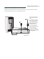
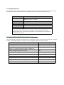
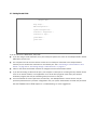
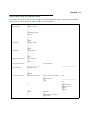
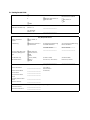
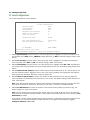
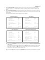
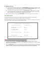
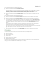
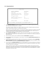
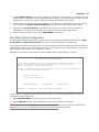
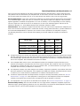
™
Netopia 4622 T1 Router
Getting Started Guide
MAKING BROADBAND WORK™
Copyright
©2002 Netopia, Inc., v.120302
All rights reserved. Printed in the U.S.A.
This manual and any associated artwork, software, and product designs are copyrighted with
all rights reserved. Under the copyright laws such materials may not be copied, in whole or
part, without the prior written consent of Netopia, Inc. Under the law, copying includes
translation to another language or format.
Netopia is a registered trademark, and “Making Broadband Work” is a trademark of Netopia,
Inc. All rights reserved.
Netopia, Inc.
2470 Mariner Square Loop
Alameda, CA 94501-1010
U.S.A.
Part Number
For additional copies of this electronic manual, order Netopia part number 6180038-00-01.
Contents
Contents
3
Chapter 1 — Introduction..........................................................1-1
Overview ....................................................................... 1-1
Features and Capabilities ............................................... 1-1
How to Use this Guide.................................................... 1-2
Chapter 2 — Making the Physical Connections..........................2-1
Find a Location .............................................................. 2-1
What You Need .............................................................. 2-1
Important Safety Instructions ......................................... 2-2
Identify the Connectors and Attach the Cables ................. 2-3
Netopia 4622 T1 Router Status Lights ............................ 2-5
Chapter 3 — Connecting to Your Local Area Network .................3-1
Readying Computers on Your Local Network..................... 3-1
Connecting to an Ethernet Network ................................. 3-2
Chapter 4 — Sharing the Connection.........................................4-1
Configuring TCP/IP on Windows-based Computers............ 4-1
Dynamic configuration (recommended)................... 4-2
Static configuration (optional)................................ 4-3
Configuring TCP/IP on Macintosh Computers ................... 4-5
Dynamic configuration (recommended)................... 4-5
Static configuration (optional)................................ 4-6
Chapter 5 — Console-Based Management .................................5-1
Connecting through a Telnet Session............................... 5-2
Configuring Telnet software ................................... 5-3
Connecting a Console Cable to Your Router ..................... 5-3
Navigating through the Console Screens.......................... 5-4
Chapter 6 — Easy Setup ...........................................................6-1
Easy Setup Console Screens .......................................... 6-1
Accessing the Easy Setup console screens ............ 6-1
Quick Easy Setup Connection Path.................................. 6-3
T1 Line Configuration............................................ 6-6
G
4
Getting Started Guide
Easy Setup Profile ................................................ 6-8
IP Easy Setup ...................................................... 6-9
Easy Setup Security Configuration ....................... 6-11
Appendix A — Technical Specifications and Safety Information ..A-1
Description.................................................................... A-1
Power requirements ............................................. A-1
Environment ........................................................ A-1
Software and protocols......................................... A-1
Agency Approvals........................................................... A-1
Regulatory notices ............................................... A-2
Important safety instructions ................................ A-4
Introduction 1-1
Chapter 1
Introduction
Overview
The Netopia 4622 T1 Router is a full-featured, stand-alone T1 router for connecting diverse local area networks
(LANs) to the Internet and other remote networks. The Netopia 4622 T1 Router uses a high performance T1
line to provide your whole network with a high-speed connection to the outside world.
This section covers the following topics:
■
“Features and Capabilities” on page 1-1
■
“How to Use this Guide” on page 1-2
Features and Capabilities
The Netopia 4622 T1 Router provides the following features:
■
Integrated T1 CSU/DSU for fractional or full T1 data service
■
Permanent connection to the Internet or remote sites at up to T1 speeds (1.54 Mbps)
■
Wire-speed routing (up to 1.54 Mbps) for all packet sizes
■
Supports all major T1 deployment models, including ATM, HDLC (Cisco and Copper Mountain), Frame
Relay, PPP, and PPP over Frame Relay
■
DS0 auto-detection for channelized T1 deployments
■
Eight-port 10/100BaseT Ethernet switch connects easily to an existing LAN environment
■
The Ethernet switch ports support auto-crossover and half- or full-duplex auto-sensing
■
Business-class routing features, such as RIP1, RIP2, static routes, and support for multiple subnets on the
LAN
■
Network Address Translation (NAT), NAPT, and MultiNAT for flexible use of IP addresses and server hosting
■
DHCP client, server, and relay agent for scalable deployment and private IP address management
■
Various QoS parameters, including ATM: UBR and CBR; IP: TOS bit prioritization
■
High availability solutions via LAN connected back-up default gateway router or dial-back via a modem
connected to the console port
■
Built-in firewall, packet filtering on source/destination address, service, and protocol; up to 255 rules in up
to 8 filter sets
■
IPSec VPN Gateway, supporting DES, 3DES encryption, along with IKE or manual key management
■
Built-in VPN acceleration for wire speed performance
■
PPTP VPN Gateway, supporting client or server termination
1-2 Getting Started Guide
■
Up to 15 IPSec or PPTP VPN security associations (tunnels)
■
Menu-driven interface via Telnet
■
Easy Setup with menu-driven interface
■
Console Tiered Access, 2 levels of configuration access
■
Configuration Management, up to 3 backup configurations
■
System diagnostics and logs
■
Command-line interface (CLI)
■
SNMP V1 and V2
■
TFTP or X-Modem download/upload of new firmware and configuration files
■
Utilities: ICMP ping, trace route, Telnet client, and Syslog client
■
LEDs: power, WAN, and Ethernet; link, status, and activity indications for easy monitoring and
troubleshooting
■
Wall-mountable, bookshelf (side-stackable), or desktop-stackable design for efficient space usage
How to Use this Guide
In addition to the documentation contained in the accompanying Firmware User’s Guide, this guide is designed
to get you up and running and connected to your local area network and the Internet. It is intended to be viewed
on-line, using the powerful features of the Adobe Acrobat Reader. The information display has been deliberately
designed to present the maximum information in the minimum space on your screen. You can keep this
document open while you perform any of the procedures described, and find useful information about the
procedure you are performing.
You can also print out all of the manual, or individual sections, if you prefer to work from hard copy rather than
on-line documentation. The pages are formatted to print on standard 8 1/2 by 11 inch paper. We recommend
that you print on 3-hole punched paper, so that you can put the pages in a binder for future reference.
This guide is organized into chapters describing the Netopia 4622’s advanced features. You may want to read
each chapter’s introductory section to familiarize yourself with the various features available.
Making the Physical Connections 2-1
Chapter 2
Making the Physical Connections
This section tells you how to make the physical connections to your Netopia 4622 T1 Router. This section
covers the following topics:
■
“Find a Location” on page 2-1
■
“What You Need” on page 2-1
■
“Identify the Connectors and Attach the Cables” on page 2-3
■
“Netopia 4622 T1 Router Status Lights” on page 2-5
Find a Location
When choosing a location for the Netopia T1 Router, consider:
■
Available space and ease of installation
■
Physical layout of the building and how to best use the physical space available for connecting your Netopia
T1 Router to the LAN
■
Available wiring and jacks
■
Distance from the point of installation to the next device (length of cable or wall wiring)
■
Ease of access to the front of the unit for configuration and monitoring
■
Ease of access to the back of the unit for checking and changing cables
■
Cable length and network size limitations when expanding networks
For small networks, install the Netopia 4622 near one of the LANs. For large networks, you can install the
Netopia 4622 in a wiring closet or a central network administration site.
What You Need
Locate all items that you need for the installation.
Included in your router package are:
■
The Netopia 4622 T1 Router
■
A power adapter and cord with a mini-DIN8 connector
■
One Category 5 Ethernet cable
■
One Category 5 WAN (or Line) cable
■
A DB-9 to DB-9 console cable
■
The Netopia CD containing software and documentation
2-2 Getting Started Guide
You will need:
■
A Windows–based PC or a Macintosh computer with Ethernet connectivity for configuring the Netopia 4622.
This may be built-in Ethernet or an add-on card, with TCP/IP installed and configured. See “Sharing the
Connection” on page 4-1.
■
A T1 wall outlet wired for a connection to a telephone carrier who supports T1 connections.
Important Safety Instructions
CAUTION: Depending on the power supply provided with the product, either the direct plug-in power supply
blades, power supply cord plug or the appliance coupler serves as the main power disconnect. It is
important that the direct plug-in power supply, socket-outlet or appliance coupler be located so it is readily
accessible.
CAUTION (North America Only): For use only with a CSA Certified or UL Listed Limited Power Source or
Class 2 power supply, rated 12Vdc, 1.5A.
TELECOMMUNICATION INSTALLATION CAUTIONS
When using your telephone equipment, basic safety precautions should always be followed to reduce the
risk of fire, electric shock and injury to persons, including the following:
1.
Do not use this product near water, for example, near a bathtub, wash bowl, kitchen sink or laundry
tub, in a wet basement or near a swimming pool.
2.
Avoid using a telephone (other than a cordless type) during an electrical storm. There may be a remote
risk of electrical shock from lightning.
3.
Do not use the telephone to report a gas leak in the vicinity of the leak.
SAVE THESE INSTRUCTIONS
Making the Physical Connections 2-3
Identify the Connectors and Attach the Cables
Identify the connectors and switches on the back panel and attach the necessary Netopia Router cables.
The figure below displays the back of the Netopia 4622 T1 Router.
1 Ethernet
3 Power
2 T1
Connect your computer, T1
line, and power source as
shown.
1. For a direct computer to
router Ethernet connection,
use a standard Ethernet
cable, or connect through a
hub or switch with a
standard Ethernet cable.
2. Use the supplied line
cable to connect the router
to your T1 wall outlet.
8
Ethernet
1
WAN
Console
Power
1 Computer
1 Netopia Router
3. Connect the supplied
power brick to a power outlet
and the mini-DIN8 connector
end to the router.
2-4 Getting Started Guide
Netopia 4622 back panel
8
Ethernet
1
WAN
8 port
Ethernet switch
T1 port
Console
Console port
Power
Power port
.
Port
T1 WAN port
Ethernet ports
Console port
Power port
Description
An RJ-48 jack labeled WAN for your T1 connection.
Eight RJ-45 10/100Base-T Ethernet jacks. You will use one of these to configure the
Netopia 4622. For a new installation, use an Ethernet connection. Alternatively, you can
use the console connection to run console-based management using a direct serial
connection. You can either connect your computer directly to an Ethernet port using a
standard Ethernet cable, or connect both your computer and the Netopia 4622 to an
existing LAN environment.
A DB-9 console port for a direct serial connection to the console screens. You can use
this if you are an experienced user. See “Connecting a Console Cable to Your Router” on
page 5-3.
A mini-DIN8 power adapter cable connection.
1.
Connect the mini-DIN8 connector from the power adapter to the power port, and plug the other end into an
electrical outlet.
2.
Connect one end of the Category 5 cable to the T1 port, and the other end to your T1 wall outlet.
3.
Connect the Ethernet cable to an Ethernet port on the router and the other end to your computer.
You should now have: the power adapter plugged in; the Ethernet cable connected between the router and
your computer; and the T1 cable connected between the router and the T1 wall outlet.
Making the Physical Connections 2-5
Netopia 4622 T1 Router Status Lights
The figure below represents the Netopia 4622 status light (LED) panel.
Netopia 4622 LED front panel
W
A
N
A
L
E
R
T
P
O
W
E
R
Ethernet
The following table summarizes the meaning of the various LED states and colors:
When this happens...
The power is on
The Router detects an error
The WAN has trained
An Ethernet port is connected to an Ethernet link partner
device
An Ethernet port has activity
Note: The remaining LEDs are not used.
the LEDs...
Power is green.
Alert is red.
WAN is green.
The corresponding Ethernet light is solid
green.
The corresponding Ethernet light flashes
green.
2-6 Getting Started Guide
Connecting to Your Local Area Network 3-1
Chapter 3
Connecting to Your Local Area Network
This chapter describes how to physically connect the Netopia 4622 to your local area network (LAN). Before you
proceed, make sure the Netopia 4622 is properly configured. You can customize the router’s configuration for
your particular LAN requirements using console-based management (see “Console-Based Management” on
page 5-1).
This section covers the following topics:
■
“Readying Computers on Your Local Network” on page 3-1
■
“Connecting to an Ethernet Network” on page 3-2
Readying Computers on Your Local Network
PC and Macintosh computers must have certain components installed before they can communicate through
the Netopia 4622. The following illustration shows the minimal requirements for a typical PC or Macintosh
computer.
Application software
TCP/IP stack
Ethernet Driver
Your PC
or Macintosh
computer
To the Netopia 4622
Application software: This is the software you use to send e-mail, browse the World Wide Web, read
newsgroups, etc. These applications may require some configuration. Examples include the Eudora e-mail client
and the Web browsers Microsoft Internet Explorer and Netscape Navigator.
TCP/IP stack: This is the software that lets your PC or Macintosh computer communicate using Internet
protocols. TCP/IP stacks must be configured with some of the same information you used to configure the
Netopia 4622. There are a number of TCP/IP stacks available for PC computers. Windows 95 includes a built-in
TCP/IP stack. Macintosh computers use either MacTCP or Open Transport. See “Configuring TCP/IP on
Windows-based Computers” on page 4-1. Macintosh computers use either MacTCP or Open Transport. See
“Configuring TCP/IP on Macintosh Computers” on page 4-5.
Ethernet: Ethernet hardware and software drivers enable your PC or Macintosh computer to communicate on
the LAN.
3-2 Getting Started Guide
Once the Netopia 4622 is properly configured and connected to your LAN, PC and Macintosh computers that
have their required components in place will be able to connect to the Internet or other remote IP networks.
Connecting to an Ethernet Network
You can connect a standard 10/100Base-T Ethernet network to the Netopia 4622 using its Ethernet ports.
Netopia 4622 back panel
8
Ethernet
1
WAN
8 port
Ethernet switch
Console
T1 port
Console port
Power
Power port
The Netopia 4622 in a 10/100Base-T network
To connect your 10/100Base-T network to the
Netopia 4622 through the Ethernet ports, use
standard Category 5 Ethernet cables with RJ-45
connectors.
If you have more than eight devices to connect,
you can attach additional devices using another
10- or 100Base-T hub or switch. The Ethernet
ports on the router will auto detect 10- or
100Base-T.
8
Ethernet
1
Crossover cables are not required.
PC
Macintosh
PC
10Base-T
Hub
Sharing the Connection 4-1
Chapter 4
Sharing the Connection
Once you have set up your physical local area network, you will need to configure the TCP/IP stack on each
client workstation connected to your Netopia 4622. This chapter describes how to configure TCP/IP for both
Windows-based and Macintosh computers.
This chapter explains the following topics:
■
“Configuring TCP/IP on Windows-based Computers” on page 4-1
■
“Configuring TCP/IP on Macintosh Computers” on page 4-5
Configuring TCP/IP on Windows-based Computers
Configuring TCP/IP on a Windows computer requires the following:
■
An Ethernet card (also known as a network adapter)
■
The TCP/IP protocol must be “bound” to the adapter or card
4-2 Getting Started Guide
Dynamic configuration (recommended)
To configure your PC for dynamic addressing do the following:
1.
Go to the Start
Menu/Settings/Control
Panels and double click
the Network icon. From
the Network components
list, select the
Configuration tab.
2.
Select TCP/IP-->Your Network Card. Then select
Properties. In the TCP/IP Properties screen, select the IP
Address tab. Click “Obtain an IP Address automatically”.
3.
Click on the DNS Configuration tab. Click Disable DNS.
DNS will be assigned by the router with DHCP.
4.
Click OK in this window and the next window. When
prompted, reboot the computer.
Note: You can also use these instructions to configure other computers on your network to accept IP
addresses served by the Netopia 4622.
Sharing the Connection 4-3
Static configuration (optional)
If you are manually configuring for a fixed or static IP address, perform the following:
1.
Go to Start Menu/Settings/Control Panels and double click the Network icon. From the Network
components list, select the Configuration tab.
2.
Select TCP/IP-->Your Network Card. Then select Properties. In the TCP/IP Properties screen, select the
IP Address tab. Click “Specify an IP Address.”
Enter the following:
IP Address: 192.168.1.2
Subnet Mask: 255.255.255.0
This address is an example of one that can be used to configure the router. Your ISP or network
administrator may ask you to use a different IP address and subnet mask.
4-4 Getting Started Guide
3.
Click on the Gateway tab (shown below).
Under “New gateway,” enter
192.168.1.1. Click Add. This is the
Netopia 4622’s pre-assigned IP address.
Click on the DNS Configuration tab. Click Enable DNS.
Enter the following
information:
Host: Type the name
you want to give to
this computer.
Domain: Type your
domain name. If you
don't have a domain
name, type your ISP's
domain name; for
example,
netopia.com.
DNS Server Search
Order: Type the
primary DNS IP
address given to you
by your ISP. Click
Add. Repeat this process for the secondary DNS.
Domain Suffix Search Order: Enter the same domain
name you entered above.
4.
Click OK in this window and the next window. When prompted, reboot the computer.
Note: You can also use these instructions to configure other computers on your network with manual or static
IP addresses. Be sure each computer on your network has its own IP address.
Sharing the Connection 4-5
Configuring TCP/IP on Macintosh Computers
The following is a quick guide to configuring TCP/IP for MacOS computers. Configuring TCP/IP in a Macintosh
computer requires the following:
You must have either Open Transport or Classic Networking (MacTCP) installed.
■
If you want to use the Dynamic Host Configuration Protocol (DHCP) server built into your Netopia 4622 to
assign IP addresses to your Macintoshes, you must be running Open Transport, standard in MacOS 8 and
higher and optional in earlier system versions.
You must have built-in Ethernet or a third-party Ethernet card and its associated drivers installed in your
Macintosh.
■
Dynamic configuration (recommended)
The Dynamic Host Configuration Protocol (DHCP), which enables dynamic addressing, is enabled by default in
the router. To configure your Macintosh computer for dynamic addressing do the following:
1.
Go to the Apple menu. Select Control Panels and then
TCP/IP.
2.
With the TCP/IP window open, go to the Edit menu and
select User Mode. Choose Basic and click OK.
3.
In the TCP/IP window, select “Connect via: Ethernet” and
“Configure: Using DHCP Server.”
Note: You can also use these instructions to configure other computers on your network to accept IP
addresses served by the Netopia 4622.
4-6 Getting Started Guide
Static configuration (optional)
If you are manually configuring for a fixed or static IP address,
perform the following:
1.
Go to the Apple menu. Select Control Panels and then
TCP/IP or MacTCP.
2.
With the TCP/IP window open, go to the Edit menu and
select User Mode. Choose Advanced and click OK.
Or, in the MacTCP window, select Ethernet and click the
More button.
3.
In the TCP/IP window or in the MacTCP/More window, select or type information into the fields as shown in
the following table.
Option:
Connect via:
Configure:
IP Address:
Subnet mask:
Router or Gateway address:
Name server address:
Implicit Search Path:
Starting domain name:
Select/Type:
Ethernet
Manually
192.168.1.2
255.255.255.0
192.168.1.1
Enter the primary and secondary name server
addresses given to you by your ISP
Enter your domain name; if you do not have a
domain name, enter the domain name of your ISP
4.
Close the TCP/IP or MacTCP control panel and save the settings.
5.
If you are using MacTCP, you must restart the computer. If you are using Open Transport, you do not need
to restart.
Sharing the Connection 4-7
Note: You can use these instructions to configure other computers on your network to accept IP addresses
served by the Netopia 4622.
You can also use these instructions to configure other computers on your network with manual or static IP
addresses. Be sure each computer on your network has its own IP address.
More information about configuring your Macintosh computer for TCP/IP connectivity through a Netopia 4622
can be found in Technote NIR_026, “Open Transport and Netopia Routers,” located on the Netopia Web site.
4-8 Getting Started Guide
Console-Based Management 5-1
Chapter 5
Console-Based Management
Console-based management is a menu-driven interface for the capabilities built into the Netopia 4622.
Console-based management provides access to a wide variety of features that the router supports. You can
customize these features for your individual setup. This chapter describes how to access the console-based
management screens.
This section covers the following topics:
■
“Connecting through a Telnet Session” on page 5-2
■
“Connecting a Console Cable to Your Router” on page 5-3
■
“Navigating through the Console Screens” on page 5-4
Console-based management screens contain seven entry points to the Netopia 4622 configuration and
monitoring features. The entry points are displayed in the Main Menu shown below:
Netopia 4622
Easy Setup...
WAN Configuration...
System Configuration...
Utilities & Diagnostics...
Statistics & Logs...
Quick Menus...
Quick View...
Return/Enter goes to Easy Setup -- minimal configuration.
You always start from this main screen.
■
The Easy Setup menus display and permit changing the values contained in the default connection profile.
You can use Easy Setup to initially configure the router directly through a console session.
Easy Setup menus contain up to five descendant screens for viewing or altering these values. The number
of screens depends on whether you have optional features installed.
This manual describes the Easy Setup menus to get you up and running quickly. For more advanced
features offered in the menus listed below, see the Firmware User’s Guide.
■
The WAN Configuration menu displays and permits changing your connection profile(s) and default profile,
creating or deleting additional connection profiles, and configuring or reconfiguring the manner in which you
5-2 Getting Started Guide
may be using the router to connect to more than one service provider or remote site.
■
The System Configuration menus display and permit changing:
■
IP Setup
■
Filter Sets
■
IP Address Serving
■
Network Address Translation (NAT)
■
Date and Time
■
Console Configuration
■
SNMP (Simple Network Management Protocol)
■
Security
■
Upgrade Feature Set
■
Change Device to a Bridge
■
Logging
■
The Utilities & Diagnostics menus provide a selection of several tools for monitoring and diagnosing the
router's behavior, as well as for updating the firmware and rebooting the system.
■
The Statistics & Logs menus display sets of tables and device logs that show information about your
router, your network, and their history.
■
The Quick Menus screen is a shortcut entry point to the most commonly used configuration menus that
are accessed through the other menu entry points.
■
The Quick View menu displays at a glance current real-time operating information about your router.
Connecting through a Telnet Session
Features of the Netopia 4622 can be configured through the console screens.
Before you can access the console screens through Telnet, you must have:
■
A network connection locally to the router or IP access to the router.
Note: Alternatively, you can have a direct serial console cable connection using the provided console cable for
your platform (PC or Macintosh) and the Console port on the back of the router. For more information on
attaching the console cable, see “Connecting a Console Cable to Your Router” on page 5-3.
■
Telnet software installed on the computer you will use to configure the router
Console-Based Management 5-3
Configuring Telnet software
If you are configuring your router using a Telnet session, your computer must be running a Telnet software
program.
■
If you connect a PC with Microsoft Windows, you can use a Windows Telnet application or simply run Telnet
from the Start menu.
■
If you connect a Macintosh computer, you can use the NCSA Telnet program supplied on the Netopia 4622
CD. You install NCSA Telnet by simply dragging the application from the CD to your hard disk.
Connecting a Console Cable to Your Router
You can perform all of the system configuration activities for your Netopia 4622 through a local serial console
connection using terminal emulation software, such as HyperTerminal provided with Windows 95, 98, 2000, or
NT on the PC, or ZTerm, included on the Netopia CD, for Macintosh computers.
The Netopia 4622 back panel has a connector labeled “Console” for attaching the Router to either a PC or
Macintosh computer via the serial port on the computer. (On a Macintosh computer, the serial port is called the
Modem port or Printer port. Newer Macintosh models have USB ports, so you may need a third-party adapter.)
This connection lets you use the computer to configure and monitor the Netopia 4622 via the console screens.
Netopia 4622 back panel
8
Ethernet
1
WAN
Console
Power
Console connection port
DB-9 (male)
To connect the Netopia 4622 to your computer for serial console communication, use a console cable
appropriate to your platform:
■
A DB-9 connector end attaches to a PC.
■
A DB-9 end of the Console cable attaches to the Netopia 4622’s Console port.
■
If you connect a PC with Microsoft Windows 95, 98, 2000, or NT, you can use the HyperTerminal
application bundled with the operating system.
■
If you connect a Macintosh computer, you can use the ZTerm terminal emulation program on the supplied
Netopia 4622 CD.
5-4 Getting Started Guide
Launch your terminal emulation software and configure the communications software for the values shown in
the table below. These are the default communication parameters that the Netopia 4622 uses.
Parameter
Suggested Value
Terminal type
PC: ANSI-BBS
Mac: ANSI, VT-100, or VT-200
Data bits
8
Parity
None
Stop bits
1
Speed
9600 - 57600 bits per second
Flow Control
None
Note: The router firmware contains an autobaud detection feature. If you are at any
screen on the serial console, you can change your baud rate and press Return
(HyperTerminal for the PC requires a disconnect). The new baud rate is displayed at
the bottom of the screen.
Navigating through the Console Screens
Use your keyboard to navigate the Netopia 4622’s configuration screens, enter and edit information, and make
choices. The following table lists the keys to use to navigate through the console screens.
To...
Use These Keys...
Move through selectable items in a screen or pop-up menu
Up, Down, Left, and Right Arrow
Set a change to a selected item or open a pop-up menu of
options for a selected item like entering an upgrade key
Return or Enter
Change a toggle value (Yes/No, On/Off)
Tab
Restore an entry or toggle value to its previous value
Esc
Move one item up
Up arrow or Control + K
Move one item down
Down arrow or Control + O
Display a dump of the device event log
Control + E
Display a dump of the WAN event log
Control + F
Refresh the screen
Control + L
Easy Setup 6-1
Chapter 6
Easy Setup
This chapter describes how to use the Easy Setup console screens on your Netopia 4622. After completing the
Easy Setup console screens, your router will be ready to connect to the Internet or another remote site.
Easy Setup Console Screens
Using four Easy Setup console screens, you can:
■
Modify a connection profile for your router for the connection to your ISP or remote location
■
Set up IP addresses and IP address serving
■
Password–protect configuration access to your Netopia 4622
Accessing the Easy Setup console screens
To access the console screens, Telnet to the Netopia Router over your Ethernet network or physically connect
with a serial console cable and access the Netopia Router with a terminal emulation program. See “Connecting
through a Telnet Session” on page 5-2 or “Connecting a Console Cable to Your Router” on page 5-3.
Note: Before continuing, make sure you have the information that your ISP or network administrator has given
you for configuring the Netopia Router.
The Netopia Router’s first console screen, Main Menu, appears in the terminal emulation window of the
attached PC or Macintosh computer when:
■
The Netopia Router is turned on
■
The computer is connected to the Netopia Router
■
Telnet or the terminal emulation software is running and configured correctly
A screen similar to the following Main Menu appears:
6-2 Getting Started Guide
Netopia 4622
Easy Setup...
WAN Configuration...
System Configuration...
Utilities & Diagnostics...
Statistics & Logs...
Quick Menus...
Quick View...
If you do not see the Main Menu, verify that:
■
If you are using a serial connection, that your serial port speed is the same as the Netopia 4622’s default
9600 baud, for first use.
■
The computer used to view the console screen has its serial port connected to the Netopia 4622’s
Console port or an Ethernet connection to its Ethernet port. See “Connecting a Console Cable to Your
Router” on page 5-3 or “Connecting through a Telnet Session” on page 5-2.
■
Telnet or the terminal emulation software is configured for the recommended values.
■
If you are connecting via the Console port, your computer’s serial port is not being used by another device,
such as an internal modem, or an application. Turn off all other programs (other than your terminal
emulation program) that may be interfering with your access to the port.
■
You have entered the correct password, if necessary. Your Netopia 4622’s console access may be
password protected from a previous configuration. See your system administrator to obtain the password.
See the Firmware User’s Guide chapter on “Troubleshooting” for more suggestions.
Easy Setup 6-3
Quick Easy Setup Connection Path
This section may be all you need to do to configure your Netopia 4622 T1 Router. Your service provider will
supply you with several parameter values. Below is a handy checklist:
T1 Line Configuration Screen
Operation Mode
❑ HDLC (default)
or
❑
CM-HDLC (Copper
Mountain)
or
Line Encoding
❑ ATM
❑ B8ZS (default)
or
Framing Mode
❑ AMI
❑ ESF (default)
or
AutoDetect DS0 Channels
❑ D4
❑ No (default) or
❑ Yes
Number of DS0 Channels
First DS0 Channel
_______________________
Channel Data Rate
_______________________
❑ Nx64k (default)
or
Data Link Encapsulation
❑ Nx56k
❑ Frame Relay (default)
PPP over Frame Relay Enabled:
DLCI:
❑ Off (default) or
❑ On
_______________________
LMI:
❑ ANSI (Annex D)
❑ CCITT (Annex A)
❑ LMI
❑ None
or
❑ PPP
PPP Mode:
or
❑ VC Multiplexed (default) or
❑ LLC SNAP
6-4 Getting Started Guide
❑ RFC1483
RFC1483 Mode:
or
❑ Bridged 1483 (default) or
❑ Routed 1483
(for Bridged 1483 only)
PPP over Ethernet (PPPoE)
❑ Off (default) or
❑ On
❑ HDLC
Data Circuit
(ATM Operation Mode only)
VPI (0-255):
(default is 0)
_______________________
VCI (32-65535):
(default is 35)
_______________________
Easy Setup Profile Screen
Address Translation
Enabled:
IP Addressing:
(for Frame Relay DLEs only)
Frame Relay Management
Type:
(for PPP DLEs only)
PPP Authentication:
❑ Yes (default) or
❑ No
❑ Numbered (default) or
❑ Unnumbered
❑ ANSI (Annex D)
❑ CCITT (Annex A)
❑ LMI
❑ None
❑ None (default),
❑ PAP or
❑ CHAP
(for Numbered IP Addressing)
Local WAN IP Address:
_______________________
Local WAN IP Mask:
_______________________
(for Unnumbered IP Addressing)
Remote IP Address:
_______________________
Remote IP Mask:
_______________________
(for PAP or CHAP)
User Name (or Host Name):
(for PAP or CHAP)
Password (or Secret):
_______________________
_______________________
IP Easy Setup Screen
Ethernet IP Address:
_______________________
Ethernet Subnet Mask:
_______________________
Domain Name:
_______________________
Primary Domain Name
Server:
_______________________
Secondary Domain Name
Server:
_______________________
Default IP Gateway:
_______________________
(192.168.1.1
255.255.255.0
are defaults)
Easy Setup Security Configuration Screen
Write Access Name:
_______________________
Write Access Password:
_______________________
Easy Setup 6-5
The following steps will get you up and running quickly:
1.
Open a Telnet session to 192.168.1.1 to bring up the Main Menu.
If you don't know how to do this, see “Connecting through a Telnet Session” on page 5-2.
Alternatively, you can connect the console cable and open a direct serial console connection, using a
terminal emulator program. See “Connecting a Console Cable to Your Router” on page 5-3.
The Main Menu appears.
Netopia 4622
Easy Setup...
WAN Configuration...
System Configuration...
Utilities & Diagnostics...
Statistics & Logs...
Quick Menus...
Quick View...
2.
Select the first item on the Main Menu list, Easy Setup. Press Return to bring up the T1 Line Configuration
menu screen.
6-6 Getting Started Guide
T1 Line Configuration
The T1 Line Configuration screen appears.
T1 Line Configuration
Operation Mode...
Line Encoding...
Framing Mode...
HDLC
B8ZS
ESF
AutoDetect DS0 Channels:
Number of DS0 Channels:
First DS0 Channel:
No
1
1
Channel Data Rate...
Nx64k
Data Link Encapsulation...
PPP over Frame Relay Enabled:
Frame Relay
Off
TO MAIN MENU
NEXT SCREEN
Return/Enter goes to new screen.
Enter Information supplied to you by your telephone company.
1.
Select Operation Mode and press Return. From the pop-up menu, highlight the mode your telephone service provider uses: HDLC (Cisco), CM-HDLC (Copper Mountain), or ATM. The default setting is HDLC. Press
Return.
2.
Select Line Encoding and press Return. From the pop-up menu, highlight the encoding your telephone
service provider uses: B8Zs or AMI. The default setting is B8Zs. Press Return.
3.
Select Framing Mode and press Return. From the pop-up menu, highlight either ESF or D4, depending on
the framing mode that your telephone service provider advises you to use. The default setting is ESF. Press
Return.
4.
Select AutoDetect DS0 Channels. Netopia routers whose model number ends in “-T” may be able to use
the auto detection feature. Toggle this item to Yes if your service provider uses equipment that supports
DS0 channel auto detection. Otherwise accept the default No.
5.
Select Number of DS0 Channels and enter the number of DS0 channels that you and your telephone
service provider have determined are necessary for your T1 line. The default setting for DS0 Channels is 1
(one). Press Return.
Note: Each DS0 channel represents a 56k or 64k increment in bandwidth. Selecting a number less than
the maximum specifies a fractional-T1 interface. You can have a maximum of 24 DS0 channels.
6.
Select First DS0 Channel and enter the number of the first active DS0 channel you will be using. The
default setting is 1 (one). Press Return.
Note: You can change the First DS0 Channel number, which has a valid range from one to the maximum
number minus the number of active channels. If the number of active DS0 channels is 24 (maximum), First
DS0 Channel is hidden.
If you specify a number of DS0 channels less than the maximum, a Contiguous Channels item appears. For
fractional-T1, you can specify whether the DS0 channels are contiguous or alternating by toggling
Contiguous Channels to Yes or No.
Easy Setup 6-7
7.
Select Channel Data Rate and highlight the data rate that your service provider has designated your
channel to connect at. The channel data rate choices are Nx56k or Nx64k. The default is Nx64k. Press
Return.
8.
Select Data Link Encapsulation and highlight the method of encapsulation that you want to use from the
pop-up menu. The choices offered are PPP, RFC1483, HDLC (Cisco), and Frame Relay. The default setting
is Frame Relay.
The screen will offer different options depending on your selection.
Frame Relay Options
PPP Options
T1 Line Configuration
T1 Line Configuration
Operation Mode...
Line Encoding...
Framing Mode...
Normal
B8ZS
ESF
Operation Mode...
Line Encoding...
Framing Mode...
Normal
B8ZS
ESF
Number of DS0 Channels:
First DS0 Channel:
1
1
Number of DS0 Channels:
First DS0 Channel:
1
1
Channel Data Rate...
Nx64k
Channel Data Rate...
Nx64k
Data Link Encapsulation...
PPP over Frame Relay Enabled:
DLCI:
LMI:
Frame Relay
On
16
None
Data Link Encapsulation...
PPP Mode...
PPP
VC Multiplexed
TO MAIN MENU
NEXT SCREEN
TO MAIN MENU
NEXT SCREEN
Return/Enter takes you back to previous screen.
Enter Information supplied to you by your telephone company.
RFC 1483 Options
Return/Enter takes you back to previous screen.
Enter Information supplied to you by your telephone company.
ATM Operation Mode Options
T1 Line Configuration
Normal
B8ZS
ESF
Operation Mode...
Line Encoding...
Framing Mode...
ATM
B8ZS
ESF
Number of DS0 Channels:
First DS0 Channel:
1
1
Number of DS0 Channels:
First DS0 Channel:
1
1
Channel Data Rate...
Nx64k
Data Link Encapsulation...
RFC1483 Mode...
PPP over Ethernet (PPPoE):
RFC1483
Bridged 1483
Off
Data Link Encapsulation...
RFC1483 Mode...
PPP over Ethernet (PPPoE):
Data Circuit VPI (0-255):
Data Circuit VCI (32-65535):
RFC1483
Bridged 1483
Off
0
35
TO MAIN MENU
NEXT SCREEN
TO MAIN MENU
NEXT SCREEN
Return/Enter goes to new screen.
Enter Information supplied to you by your telephone company.
■
T1 Line Configuration
Operation Mode...
Line Encoding...
Framing Mode...
Return/Enter goes to new screen.
Enter Information supplied to you by your telephone company.
If you selected Frame Relay as a Data Link Encapsulation method, the PPP over Frame Relay Enabled
toggle appears.
If you toggle PPP over Frame Relay Enabled to On, the DLCI field appears, allowing you to enter a DLCI
value (16 is the default). The LMI option also appears, allowing you to select from ANSI (Annex D),
CCITT (Annex A), LMI, or None from the pull-down menu.
■
If you selected PPP, the next pop-up menu PPP Mode offers the choice of VC Multiplexed or LLC SNAP.
6-8 Getting Started Guide
9.
■
If you selected RFC1483, the next pop-up menu RFC1483 Mode offers the choice of Bridged 1483 or
Routed 1483. If you select Bridged 1483, a new option PPP over Ethernet (PPPoE) appears. You can
then toggle PPPoE On or Off. Choosing Routed 1483 hides the PPPoE option.
■
If you selected ATM Operation Mode in Step 1, the Data Circuit VPI and VCI fields become visible.
These are editable fields. The default values 0 and 35 are typical for ADSL circuits, so you will only
need to change them if your service provider explicitly tells you to do so.
Press the Down arrow key until you reach NEXT SCREEN. Press Return to bring up the next screen.
Easy Setup Profile
The Easy Setup Profile screen is where you configure the parameters that control the Netopia 4622’s
connection to a specific remote destination, usually your ISP or a corporate site.
On a Netopia 4622 you can add up to 15 more connection profiles, for a total of 16, although you can only use
one at a time, unless you are using Virtual Private Networks (VPNs).
Connection Profile 1: Easy Setup Profile
Connection Profile Name:
Easy Setup Profile
Address Translation Enabled:
IP Addressing...
Yes
Numbered
Local WAN IP Address:
Local WAN IP Mask:
0.0.0.0
0.0.0.0
Frame Relay Management Type...
ANSI (Annex D)
PREVIOUS SCREEN
NEXT SCREEN
Return/Enter brings you to next screen.
Enter basic information about your WAN connection with this screen.
Note: The appearance of this screen varies, depending on the settings in the previous screen.
1.
To enable address translation, toggle Address Translation Enabled to Yes (the default). For more
information on Network Address Translation, see the Firmware User’s Guide chapter on “Multiple Network
Address Translation (MultiNAT)“.
2.
From the IP Addressing menu item, choose between Unnumbered and Numbered addressing. Numbered is
the default for ADSL. It assigns a unique IP address to the ADSL WAN interface, as required by most ISPs’
routers. Unnumbered may be used for simpler configurations such as point-to-point applications.
Easy Setup 6-9
If you selected Numbered, the following fields appear.
■
Select the editable field labeled Local WAN IP Address.
The default address is 0.0.0.0, which allows for dynamic addressing, when your ISP assigns an address
each time you connect. However, you can enter another specific address if you want to use static
addressing. In that case, enter the local WAN address your ISP gave you. Press Return.
■
Select the editable field labeled Local WAN IP Mask. Enter the mask address your ISP gave you. Press
Return.
If you selected Unnumbered, the following fields appear.
■
Select the editable field labeled Remote IP Address and enter the remote IP address. Press Return.
■
Select the editable field labeled Remote IP Mask and enter the remote mask address. Press Return.
3.
If you selected PPP data link encapsulation in the DSL Line Configuration screen, a PPP Authentication
menu item appears. The authentication protocol and user name/password combinations you enter must
be assigned or agreed to in advance between you and your ISP. Select PPP Authentication and press
Return.
From the pop-up menu that appears, select the authentication method your ISP uses: PAP (Password
Authentication Protocol), CHAP (Challenge Handshake Authentication Protocol), or None.
4.
■
PAP is the most common, and requires you to enter a User Name and Password in the next two fields.
■
CHAP requires you to enter a Host Name and Secret in the next two fields.
Press the Down arrow key until you reach NEXT SCREEN. Press Return to bring up the next screen.
IP Easy Setup
The IP Easy Setup screen is where you enter information about your Netopia Router’s:
■
Ethernet IP address
■
Ethernet Subnet mask
■
Domain Name
■
Domain Name Server IP address
■
Default gateway IP address
Consult with your network administrator to obtain the information you will need. For more information about
setting up IP, see the Firmware User’s Guide chapter on “IP Setup”.
6-10 Getting Started Guide
IP Easy Setup
Ethernet IP Address:
Ethernet Subnet Mask:
192.168.1.1
255.255.255.0
Domain Name:
Primary Domain Name Server:
Secondary Domain Name Server:
isp.net
209.3.224.21
209.3.224.20
Default IP Gateway:
127.0.0.2
IP Address Serving:
On
Number of Client IP Addresses:
1st Client Address:
100
192.168.1.100
PREVIOUS SCREEN
NEXT SCREEN
Enter an IP address in decimal and dot form (xxx.xxx.xxx.xxx).
Set up the basic IP & IPX attributes of your Netopia in this screen.
1.
Select Ethernet IP Address and enter the first IP address from the IP address range your ISP has given
you. This will be the Netopia Router’s IP address.
The Ethernet IP Address defaults to an address (192.168.1.1) within a range reserved by the Internet
address administration authority for use within private networks.
Because this is a private network address, it should never be directly connected to the Internet. Using NAT
for all your connection profiles will ensure this restriction. See the Firmware User’s Guide chapter on
“Multiple Network Address Translation (MultiNAT)” for more information.
2.
Select Ethernet Subnet Mask and enter the subnet mask your ISP has given you. The Ethernet Subnet
Mask defaults to a standard class mask derived from the class of the Ethernet IP address you entered in
the previous step.
3.
Press the Down arrow key until the editable field labeled Domain Name is highlighted.
4.
Type the Domain Name your ISP gave you. Press Return. The next field Primary Domain Name Server will
be highlighted.
5.
Type the Primary Domain Name Server address your ISP gave you. Press Return. A new field Secondary
Domain Name Server will appear. If your ISP gave you a secondary domain name server address, enter it
here. Press Return until the next field Default IP Gateway is highlighted.
6.
If you do not enter a Default IP Gateway value, the router defaults to the remote IP address you entered in
the Easy Setup connection profile. If the Netopia Router does not recognize the destination of any IP traffic,
it forwards that traffic to this gateway.
Do not confuse the remote IP address and the Default IP Gateway’s address with the block of local IP
addresses you may receive from your ISP. You use the local IP addresses for the Netopia 4622’s Ethernet
port and for IP clients on your local network. The remote IP address and the default gateway’s IP address
should point to your ISP’s router.
Easy Setup 6-11
7.
Toggle IP Address Serving to On or Off, depending on whether you want the device’s IP address server to
supply dynamic IP addresses to your client workstations. Normally, you would accept the default On so that
workstations on your LAN can have IP addresses assigned dynamically from the router.
8.
The IP address server will provide 100 IP addresses automatically to workstations on your LAN. You only
need to change the Number of Client IP Addresses if you have some other IP addressing scheme.
9.
By default, the 1st Client Address is 192.168.1.100, based on the device’s default IP address of
192.168.1.1. You only need to change this if you have some other IP addressing scheme.
10. Press the Down arrow key until you reach NEXT SCREEN. Press Return.
Easy Setup Security Configuration
The Easy Setup Security Configuration screen lets you password-protect your Netopia 4622. Input your Write
Access Name and Write Access Password with names or numbers totaling up to eleven digits.
If you password protect the console screens, you will be prompted to enter the name and password you have
specified every time you log in to the console screens. Do not forget your name and password. If you do, you
will be unable to access any of the configuration screens.
Additional security features are available. See the Firmware User’s Guide chapter on “Security”.
Easy Setup Security Configuration
It is strongly suggested that you password-protect configuration access to your
Netopia. By entering a Name and Password pair here, access via serial,
Telnet, and SNMP will be password-protected.
Be sure to remember what you have typed here, because you will be prompted for
it each time you configure this Netopia.
Write Access Name:
Write Access Password:
PREVIOUS SCREEN
TO MAIN MENU
RESTART DEVICE
Configure a Configuration Access Name and Password here.
The final step in configuring the Easy Setup console screens is to restart the Netopia 4622, so that the
configuration settings take effect.
1.
Select RESTART DEVICE. A prompt asks you to confirm your choice.
2.
Select CONTINUE to restart the Netopia Router and have your selections take effect.
Note: You can also restart the system at any time by using the Restart System utility in the Utilities and
Diagnostics menu, or by turning the Netopia Router off and on with the power switch.
6-12 Getting Started Guide
The Router will restart and your configuration settings will be activated. You can then Exit or Quit your Telnet
application.
Easy Setup is now complete.
Technical Specifications and Safety Information A-1
Appendix A
Technical Specifications and Safety Information
Description
Dimensions: 124.0 cm (w) x 20.0 cm (d) x 5.3 cm (h); 9.4” (w) x 7.9” (d) x 2.1” (h)
Communications interfaces: The Netopia 4622 T1 Router has an RJ-48 jack for the T1 connection; eight RJ-45
10/100Base-T Ethernet ports for your LAN connections; and a DB-9 Console port.
Power requirements
■
12 VDC input
■
1.5 Amps
Environment
Operating temperature: 0° to +40° C
Storage temperature: 0° to +70° C
Relative storage humidity: 20 to 80% non-condensing
Software and protocols
Software media: Software preloaded on internal flash memory; field upgrades done via download to internal
flash memory via XMODEM or TFTP
Routing: TCP/IP Internet Protocol Suite, RIP
WAN support: PPP, HDLC, ATM, Frame Relay
Security: PAP, CHAP, MS-CHAP, IP firewalls, and UI password security
SNMP network management: SNMPv1, SNMPv2, MIB-II (RFC 1213), Interface MIB (RFC 1229), Ethernet MIB
(RFC 1643), Netopia MIB.
Management/configuration methods: serial console, remote modem console, Telnet, SNMP
Diagnostics: PING, event logging, routing table displays, traceroute, statistics counters
Agency Approvals
North America
Safety Approvals:
■
United States – UL Standard for Information Technology Equipment, UL 60950, Third Edition, Dated
A-2 Getting Started Guide
December 1, 2000
■
Canada – CSA: CAN/CSA-C22.2 No. 950-95
EMI:
■
FCC Part 15 Class B
■
FCC Part 68
Regulatory notices
Warnings
This is a Class B product. In a domestic environment this product may cause radio interference, in which case
the user may be required to take adequate measures. Adequate measures include increasing the physical
distance between this product and other electrical devices.
Changes or modifications to this unit not expressly approved by the party responsible for compliance could void
the user’s authority to operate the equipment.
United States. This equipment has been tested and found to comply with the limits for a Class B digital device,
pursuant to Part 15 of the FCC Rules. These limits are designed to provide reasonable protection against
harmful interference in a residential installation. This equipment generates, uses, and can radiate radio
frequency energy and, if not installed and used in accordance with the instructions, may cause harmful
interference to radio communications. However, there is no guarantee that interference will not occur in a
particular installation. If this equipment does cause harmful interference to radio or television reception, which
can be determined by turning the equipment off and on, the user is encouraged to try to correct the
interference by one or more of the following measures:
■
Reorient or relocate the receiving antenna.
■
Increase the separation between the equipment and receiver.
■
Connect the equipment into an outlet on a circuit different from that to which the receiver is connected.
■
Consult the dealer or an experienced radio TV technician for help.
FCC Requirements, Part 68. The Federal Communications Commission (FCC) has established Rules which
permit this device to be directly connected to the telephone network. Standardized jacks are used for these
connections. This equipment should not be used on party lines or coin phones.
If this device is malfunctioning, it may also be causing harm to the telephone network; this device should be
disconnected until the source of the problem can be determined and until repair has been made. If this is not
done, the telephone company may temporarily disconnect service.
The telephone company may make changes in its technical operations and procedures; if such changes affect
the compatibility or use of this device, the telephone company is required to give adequate notice of the
changes. You will be advised of your right to file a complaint with the FCC.
If the telephone company requests information on what equipment is connected to their lines, inform them of:
a) The telephone number to which this unit is connected.
b) The ringer equivalence number
c) The USOC jack required. (RJ48C)
d) The FCC Registration Number. (14 digits provided by FCC)
Technical Specifications and Safety Information A-3
Items (b) and (d) are indicated on the label. The Ringer Equivalence Number (REN) is used to determine how
many devices can be connected to your telephone line. In most areas, the sum of the REN's of all devices on
any one line should not exceed five (5.0). If too many devices are attached, they many not ring properly.
Service Requirements. In the event of equipment malfunction, all repairs should be performed by our Company
or an authorized agent. Under FCC rules, no customer is authorized to repair this equipment. This restriction
applies regardless of whether the equipment is in or our of warranty. It is the responsibility of users requiring
service to report the need for service to our Company or to one of our authorized agents. Service can be
obtained at Netopia, Inc., 2470 Mariner Square Loop, Alameda, California, 94501.
FCC Information. This equipment complies with Part 68 of the FCC rules and the requirements adopted by the
ACTA. On the bottom of this equipment is a label that contains, among other information, a product identifier in
the format US:AAAEQ##TXXXX. If requested, this number must be provided to the telephone company.
The following information may be required when applying to the local telephone company for leased line
facilities:
Service Type
SOC
FIC
USOC
1.544 Mbps - SF
6.0F
04DU9-BN
RJ-48C
1.544 Mbps – SF and B8ZS
6.0F
04DU9-DN
RJ-48C
1.544 Mbps – ESF
6.0F
04DU9-1KN
RJ-48C
1.544 Mbps – ESF and B8ZS
6.0F
04DU9-1SN
RJ-48C
■
A plug and jack used to connect this equipment to the premises wiring and telephone network must comply
with the applicable FCC Part 68 rules and requirements adopted by the ACTA. A compliant telephone cord
and modular plug is provided with this product. It is designed to be connected to a compatible modular jack
that is also compliant. See installation instructions for details.
■
If this Netopia 4622 causes harm to the telephone network, the telephone company will notify you in
advance that temporary discontinuance of service may be required. But if advance notice isn’t practical,
the telephone company will notify you as soon as possible. Also, you will be advised of your right to file a
complaint with the FCC if you believe it is necessary.
■
The telephone company may make changes in its facilities, equipment, operations or procedures that could
affect the operation of the equipment. If this happens the telephone company will provide advance notice
in order for you to make necessary modifications to maintain uninterrupted service.
■
If trouble is experienced with this Netopia 4622, for repair or warranty information, please see “Service
Requirements” on page A-3. If the equipment is causing harm to the telephone network, the telephone
company may request that you disconnect the equipment until the problem is resolved.
■
This equipment is of a type that is not intended to be repaired. See “Service Requirements” on page A-3
Electrical Safety Advisory: Users should consider use of a surge arrestor. Telephone companies report that
electrical surges, typically lightning transients, are very destructive to customer terminal equipment connected
to AC power sources. This has been identified as a major nationwide problem.
A-4 Getting Started Guide
Important
This product was tested for FCC compliance under conditions that included the use of shielded cables and
connectors between system components. Changes or modifications to this product not authorized by the
manufacturer could void your authority to operate the equipment.
Canada. This digital apparatus does not exceed the Class B limits for radio noise emission from digital
apparatus set out in the Radio Interference Regulations of the Canadian Department of Communications.
Le présent appareil numérique n'émet pas de bruits radioélectriques dépassant les limites applicables aux
appareils numériques de la classe A prescrites dans le Réglement sur le brouillage radioélectrique édicté par le
ministère des Communications du Canada.
Declaration for Canadian users
The Canadian Industry Canada label identifies certified equipment. This certification means that the equipment
meets certain telecommunications network protective, operation and safety requirements. The Department
does not guarantee the equipment will operate to the user’s satisfaction.
Before installing this equipment, users should ensure that it is permissible to be connected to the facilities of
the local telecommunications company. The equipment must also be installed using an acceptable method of
connection. In some cases, the company’s inside wiring associated with a single line individual service may be
extended by means of a certified connector assembly (telephone extension cord.) The customer should be
aware that compliance with the above conditions may not prevent degradation of service in some situations.
Repairs to the certified equipment should be made by an authorized Canadian maintenance facility designated
by the supplier. Any repairs or alterations made by the user to this equipment, or equipment malfunctions, may
give the telecommunications company cause to request the user to disconnect the equipment.
Users should ensure for their own protection that the electrical ground connections of the power utility,
telephone lines and internal metallic water pipe system, if present, are connected together. This precaution
may be particularly important in rural areas.
Caution
Users should not attempt to make such connections themselves, but should contact the appropriate electric
inspection authority, or electrician, as appropriate.
The Load Number (LN) assigned to each terminal device denotes the percentage of the total load to be
connected to a telephone loop which is used by the device, to prevent overloading. The termination on a loop
may consist of any combination of devices subject only to the requirement that the total of the Load Numbers of
all the devices does not exceed 100.
Important safety instructions
Caution
■
Depending on the power supply provided with the product, either the direct plug-in power supply blades,
power supply cord plug or the appliance coupler serves as the mains power disconnect. It is important that
the direct plug-in power supply, socket-outlet or appliance coupler be located so it is readily accessible.
■
(North America Only) For use only with a CSA Certified or UL Listed Limited Power Source or Class 2 power
Technical Specifications and Safety Information A-5
supply, rated 12Vdc, 1.5A.
Telecommunication installation cautions
When using your telephone equipment, basic safety precautions should always be followed to reduce the risk of
fire, electric shock and injury to persons, including the following:
■
Do not use this product near water, for example, near a bathtub, wash bowl, kitchen sink or laundry tub, in
a wet basement or near a swimming pool.
■
Avoid using a telephone (other than a cordless type) during an electrical storm. There may be a remote risk
of electrical shock from lightning.
■
Do not use the telephone to report a gas leak in the vicinity of the leak.Never install telephone wiring
during a lightning storm.
A-6 Getting Started Guide