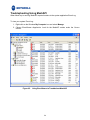
1
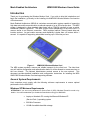
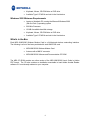
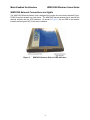
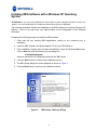
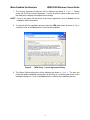
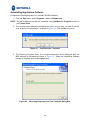
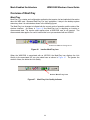
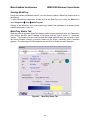
MEA
3.1
WMC6300
Wireless Modem Card
Windows 2000 and XP
Users Guide
Documentation Revision 3.1.8
Copyrights
The Motorola products described in this document may include copyrighted Motorola computer programs. Laws in the
United States and other countries reserve for Motorola certain exclusive rights for copyrighted computer programs.
Accordingly, any copyrighted Motorola computer programs contained in the Motorola products described in this
document may not be copied or reproduced in any manner without the express written permission of Motorola.
Furthermore, the purchase of Motorola products shall not be deemed to grant either directly or by implication,
estoppels or otherwise, any license under the copyrights, patents or patent applications of Motorola, except for the
normal nonexclusive, royalty-free license to use that arises by operation of law in the sale of a product.
Disclaimer
Please note that certain features, facilities and capabilities described in this document may not be applicable to or
licensed for use on a particular system, or may be dependent upon the characteristics of a particular mobile
subscriber unit or configuration of certain parameters. Please refer to your Motorola contact for further information.
Trademarks
Motorola, the Motorola logo, and all other trademarks identified as such herein are trademarks of Motorola, Inc. All
other product or service names are the property of their respective owners.
Copyrights
© 2007 Motorola, Inc. All rights reserved. No part of this document may be reproduced, transmitted, stored in a
retrieval system, or translated into any language or computer language, in any form or by any means, without the
prior written permission of Motorola, Inc.
Table of Contents
INTRODUCTION .......................................................................................................................... 1
General System Requirements........................................................................................... 1
Windows XP Minimum Requirements ............................................................................... 1
Windows 2000 Minimum Requirements............................................................................ 2
What’s in the Box................................................................................................................. 2
WMC6300 External Connections and Lights..................................................................... 3
INSTALLING MEA SOFTWARE WITH A WINDOWS XP OPERATING SYSTEM ..................... 4
INSTALLING MEA SOFTWARE WITH A WINDOWS 2000 OPERATING SYSTEM................ 12
INSTALLING THE WMC6300 WIRELESS MODEM CARD ...................................................... 19
Connect the Antenna Assembly....................................................................................... 19
Disconnecting a Pigtail Antenna Assembly .................................................................... 20
Connect the Magnetic Antenna Assembly (Optional) .................................................... 20
Insert the WMC6300 Wireless Modem Card .................................................................... 21
Configuring the DNS Address .......................................................................................... 28
Removing the WMC6300 Wireless Modem Card............................................................. 30
Uninstalling Application Software.................................................................................... 32
OVERVIEW OF MESHTRAY ..................................................................................................... 33
MeshTray ............................................................................................................................ 33
Starting MeshTray.............................................................................................................. 35
MeshTray Status Tab......................................................................................................... 35
MeshTray Configuration Tab ............................................................................................ 36
Geo Position.................................................................................................................... 36
Reporting Interval...................................................................................................................... 36
ii
Mesh Enabled Architecture
WMC6300 Windows Users Guide
Server IP Address..................................................................................................................... 36
Control Channel Configuration ........................................................................................ 37
Changing Control Channel ....................................................................................................... 37
User Priority Settings and Quality of Service Overview .................................................. 38
Classification of Data Packets .................................................................................................. 38
Differentiated Services Code Point........................................................................................... 38
User Priority .............................................................................................................................. 38
Service Differentiation Mechanisms ......................................................................................... 39
Intelligent Access Point Support for Quality of Service ............................................................ 39
Priority Levels for Local Nodes ....................................................................................... 40
Setting the Priority Level for the WMC6300 ............................................................................. 40
Addressing Schemes ...................................................................................................... 42
Network DHCP Addressing Scheme ........................................................................................ 42
Statically Provisioned Addressing Scheme .............................................................................. 43
User Supplied Addressing Scheme .......................................................................................... 43
Setting the User Supplied IP Address ...................................................................................... 43
MeshTray Security Tab...................................................................................................... 47
Allow Open Authentication .............................................................................................. 47
IAP Authentication........................................................................................................... 48
UserId and Password................................................................................................................ 48
Peer Authentication......................................................................................................... 48
MeshTray Authentication Activity Tab............................................................................. 49
MeshTray Geo-Position Tab (Optional) ........................................................................... 50
MeshTray Routing Tab (Optional) .................................................................................... 51
Routing Table.................................................................................................................. 51
Neighbor Table................................................................................................................ 51
Threshold ........................................................................................................................ 51
iii
Routing Icons .................................................................................................................. 52
Terminating MeshTray....................................................................................................... 53
TROUBLESHOOTING USING MESHAPI.................................................................................. 54
CUSTOMER SERVICE INFORMATION .................................................................................... 55
Obtaining Support ................................................................... Error! Bookmark not defined.
System Information ................................................................. Error! Bookmark not defined.
Return Material Request.......................................................... Error! Bookmark not defined.
Radio Products and Services Division .................................. Error! Bookmark not defined.
Radio Products and Services Division Telephone NumbersError! Bookmark not defined.
Returning System Components to Motorola......................... Error! Bookmark not defined.
Returning FREs........................................................................ Error! Bookmark not defined.
PRODUCT WARRANTY INFORMATION .................................................................................. 58
REGULATORY INFORMATION ................................................................................................ 61
FCC Information................................................................................................................. 61
FCC RF Energy Exposure Statement............................................................................... 61
Regulatory and RF Safety Exposure................................................................................ 61
SAFETY CERTIFICATION ...............................................ERROR! BOOKMARK NOT DEFINED.
iv
Mesh Enabled Architecture
WMC6300 Windows Users Guide
List of Figures
Figure 1.
WMC6300 Wireless Modem Card .................................................................1
Figure 2.
WMC6300 Antenna Port and LED Indicators ..............................................3
Figure 3.
MEA Setup - Welcome Dialog.......................................................................4
Figure 4.
MEA Setup - License Agreement Dialog .....................................................5
Figure 5.
MEA Setup – Startup Options Dialog ..........................................................6
Figure 6.
MEA Setup - Ready to Install Dialog............................................................6
Figure 7
MEA Setup - Drivers Previously Installed Dialog .......................................7
Figure 8.
Confirm Action – Remove Existing Components.......................................7
Figure 9.
Removing Programs From Your Computer Window .................................8
Figure 10.
Installing Files Window.................................................................................8
Figure 11.
Software Installation Dialog Box..................................................................9
Figure 12.
Software Installation Dialog Box..................................................................9
Figure 13.
Software Installation Dialog Box................................................................10
Figure 14.
MEA Setup - mea Installed Successfully Dialog Box ...............................11
Figure 15.
MEA Setup - Installer Setup Dialog Box ....................................................12
Figure 16.
MEA Setup - License Agreement Dialog Box ..........................................13
Figure 17.
MEA Setup – Startup Options Dialog Box.................................................13
Figure 18.
MEA Setup - Ready to Install Dialog Box ..................................................14
Figure 19
MEA Setup - Drivers Previously Installed Dialog Box .............................14
Figure 20.
Confirm Action – Remove Existing Components.....................................15
Figure 21.
Removing Programs From Your Computer Window ...............................15
Figure 22.
Installing Files Window...............................................................................16
Figure 23.
Digital Signature Not Found Dialog Box ...................................................16
Figure 24.
MEA Setup - Select Options Dialog Box ...................................................17
Figure 25.
Finished Popup Dialog Box........................................................................18
Figure 26.
Attach the Antenna to the WMC6300.........................................................19
v
Figure 27.
Attach Magnetic Mount Antenna to the WMC6300 ...................................21
Figure 28.
Installing the WMC6300 Wireless Modem Card ........................................21
Figure 29.
Proper Orientation of Antenna ...................................................................22
Figure 30.
Found New Hardware Popup Dialog box ..................................................22
Figure 31.
Found New Hardware Wizard – Serial PC Card ........................................23
Figure 32.
Found New Hardware Wizard - Loading Files...........................................23
Figure 33.
Hardware Installation Dialog Box ..............................................................24
Figure 34.
Found New Hardware Wizard - Complete .................................................24
Figure 35.
Found New Hardware Wizard – WMC6300 PC Card .................................25
Figure 36.
Found New Hardware Wizard Loading Files.............................................25
Figure 37.
Hardware Installation Dialog Box - WMC6300 PC Card ...........................26
Figure 38.
Found New Hardware Wizard Complete....................................................26
Figure 39.
Found New Hardware - Wizard Complete .................................................27
Figure 40.
Local Area Connection Properties Dialog Box .........................................28
Figure 41.
Unplug or Eject Hardware Icon ..................................................................30
Figure 42.
Safe to Remove Hardware - WMC6300 Card .............................................30
Figure 43.
Removing the WMC6300 from the PCMCIA slot .......................................31
Figure 44.
Confirm Action - Uninstall ..........................................................................32
Figure 45.
Removing Programs from Your Computer Dialog Box ...........................32
Figure 46.
Inactive MeshTray Icon ...............................................................................33
Figure 47.
MeshTray Link Quality Indicator ................................................................33
Figure 48.
MeshTray No IP Address Acquired Icon ...................................................34
Figure 49.
MeshTray Status Tab ..................................................................................35
Figure 50.
MeshTray Configuration Tab......................................................................36
Figure 51.
Password Protection Panel ........................................................................37
Figure 52.
MeshTray Configuration Tab Priority Settings .........................................40
Figure 53.
MeshTray Configuration Tab Addressing Scheme ..................................42
Figure 54.
Control Panel – Network and Internet Connections Icon ........................44
Figure 55.
Network and Dial-up Connections Window ..............................................44
vi
Mesh Enabled Architecture
WMC6300 Windows Users Guide
Figure 56.
Local Area Connection Properties Dialog Box .........................................45
Figure 57.
Internet Protocol (TCP/IP) Properties Dialog Box ....................................46
Figure 58.
MeshTray Security Tab ...............................................................................47
Figure 59.
Peer Authentication – Add..........................................................................48
Figure 60.
MeshTray Authentication Activity Tab ......................................................49
Figure 61.
MeshTray Geo Position Tab .......................................................................50
Figure 62.
MeshTray Geo Position Spherical Coordinates .......................................50
Figure 63.
MeshTray Routing Tab................................................................................51
Figure 64.
Exit MeshTray ..............................................................................................53
Figure 65.
Using EventViewer to Troubleshoot MeshAPI..........................................54
vii
Mesh Enabled Architecture
WMC6300 Windows Users Guide
Introduction
Thank you for purchasing the Wireless Modem Card. If you wish to skip this introduction and
begin the installation, go directly to the Installing the WMC6300 Wireless Modem Card section
of this document.
Mesh Enabled Architecture (MEA®) is a wireless communication system capable of supporting
high data rate mobile communication at vehicular speeds of up to 250 miles per hour. The MEA
system is designed to allow standard client hosts with a PCMCIA interface to have a mobile
broadband Ethernet connection. The MEA system works transparently to the client host in a
manner similar to an Ethernet connection. MEA provides Internet Protocol based data and
location services. Its geo-location accuracy and availability is better than ±10 meters within 1
second. It is capable of supporting subscribers traveling up to 100 miles per hour.
Figure 1.
WMC6300 Wireless Modem Card
The MEA system provides a secure and reliable transport for the client host. The client host
may still require configuration and authentication before it will be allowed to access services on
the core network. The Network Administrator controls access to the core network. This
document provides detailed installation and configuration instructions for installing the MEA
WMC6300 Wireless Modem Card and supporting software.
General System Requirements
Host computers must comply with the following minimum requirements to ensure optimal
performance for the WMC6300.
Windows XP Minimum Requirements
ATTENTION: If you are running Windows XP Service Pack 2 (SP2), Windows Firewall is turned on by
default. It is recommended that you disable the firewall when using your WMC6300.
•
Laptop or Notebook PC running the Microsoft Windows XP
(Service Pack 1) operating system
•
500 MHz Processor
•
10 MB of available hard disk storage
1
•
Keyboard, Mouse, CD-ROM drive or DVD drive
•
Available Type II PCMCIA card slot in the Host device
Windows 2000 Minimum Requirements
•
Laptop or Notebook PC running the Microsoft Windows 2000
(Service Pack 3) operating system
•
500 MHz Processor
•
10 MB of available hard disk storage
•
Keyboard, Mouse, CD-ROM drive or DVD drive
•
Available Type II PCMCIA card slot in the Host device
What’s in the Box
Each MEA WMC6300 Wireless Modem Card is a full-featured wireless networking interface.
The following is a list of the items provided with each WMC6300 card:
•
MEA WMC6300 Wireless Modem Card
•
Antenna with a MMCX connector
•
MEA WMC6300 Software and Documentation CD ROM
The MEA CD ROM contains an online version of the MEA WMC6300 User’s Guide in Adobe
PDF format. The CD also contains an installation executable to load Adobe Acrobat Reader
software if it is not already resident on your computer.
2
Mesh Enabled Architecture
WMC6300 Windows Users Guide
WMC6300 External Connections and Lights
The WMC6300 Wireless Modem Card is designed for insertion into an industry-standard Type II
PCMCIA card slot located in a Host device. The WMC6300 has an antenna port to connect the
external antenna and two LED Indicators. As shown in Figure 2 the red LED is the transmit
indicator and the green LED is the receive indicator.
Figure 2.
WMC6300 Antenna Port and LED Indicators
3
Installing MEA Software with a Windows XP Operating
System
ATTENTION: If you are running Windows XP Service Pack 2 (SP2), Windows Firewall is turned on by
default. It is recommended that you disable the firewall when using your WMC6300.
The following procedure outlines the installation of the MEA software on a typical Windows XP
platform. Some of the steps may vary slightly based on the configuration of the individual
computers.
Complete the following procedure to install the MEA software:
1. Close and exit any existing MEA applications running on the computer prior to
installation.
2. Insert the MEA Software and Documentation CD into the CD-ROM drive.
3. If the installation program does not start automatically, open the Windows Start menu.
Click on Run then type the following into the dialog box:
d:setupmeaclient.exe
where d: specifies the CD-ROM drive and click the “OK” button.
4. Click the “Next” button to continue the installation process.
5. The MEA Setup dialog box will be displayed as shown in Figure 3.
6. Click the Next button to continue the installation process.
Figure 3.
MEA Setup - Welcome Dialog
4
Mesh Enabled Architecture
WMC6300 Windows Users Guide
7. The License Agreement dialog box will be displayed as shown in Figure 4. Please
review the End User License Agreement. Use the scroll bar located at the right side of
the dialog box to display the complete text message.
NOTE: If you do not agree with the terms of the license agreement, click on Cancel and the
installation will be terminated.
8. To continue with the installation process, select the YES radio button as shown in Figure
4 and then click on the Next button to continue the installation.
Figure 4.
MEA Setup - License Agreement Dialog
9. The Startup Options dialog box will be displayed as shown in Figure 5. The user can
modify the default installation configuration by checking or un-checking the boxes on this
installation dialog box. Click on the Next button to continue the installation process.
5
Figure 5.
MEA Setup – Startup Options Dialog
10. The Ready to Install dialog box will be displayed as shown in Figure 6. This dialog box
displays the Install Folder location and the Shortcut Folder name that will be used to
install the MEA software. Click on the Next button to proceed with the installation
process.
Figure 6.
MEA Setup - Ready to Install Dialog
11. If MEA was previously installed on your computer, the Information dialog box will be
displayed as shown in Figure 7. Click on the Uninstall button to uninstall the existing
6
Mesh Enabled Architecture
WMC6300 Windows Users Guide
MEA drivers and continue the installation process. If you do not want to continue, click
the Cancel button.
Figure 7
MEA Setup - Drivers Previously Installed Dialog
12. The Confirm Action dialog will be displayed. Click on the Yes button to remove all of the
previously installed components. If you do not want to continue, click on the No button.
Figure 8.
Confirm Action – Remove Existing Components
7
13. If you choose to continue with the installation, the Removing Programs From Your
Computer dialog will be displayed to indicate the progress of the uninstall operation.
When the operation is complete, click on the Close button to dismiss the dialog.
Figure 9.
Removing Programs From Your Computer Window
14. The Installing Files window will be displayed. It will be dismissed as soon as the
installation of the files is complete.
Figure 10.
Installing Files Window
8
Mesh Enabled Architecture
WMC6300 Windows Users Guide
15. The Performing Setup Actions dialog box displays a status bar to indicate the progress
of the installation.
16. If the Software Installation dialog box is displayed as shown in Figure 11, it indicates that
the software is not Windows Logo tested. Click on the Continue Anyway button to
complete the installation process.
Figure 11.
Software Installation Dialog Box
17. A second Software Installation dialog box is displayed as shown in Figure 12. It
indicates the software you are installing is not Windows Logo tested. Click on the
Continue Anyway button to complete the installation process.
Figure 12.
Software Installation Dialog Box
9
18. The Select Options dialog box will be displayed as shown in Figure 13. This dialog box
allows the user to view the ReadMe file for the most current release information. It also
allows the user to immediately run MeshTray. Click on the Next button to proceed with
the installation process.
Figure 13.
Software Installation Dialog Box
19. If selected, the ReadMe file will be displayed. Review the contents of the file and then
dismiss the dialog box by clicking on the X located in the upper right corner of the dialog
box.
20. The mea Installed Successfully dialog box will appear as shown in Figure 14. Click on
the Finish button to exit.
10
Mesh Enabled Architecture
Figure 14.
WMC6300 Windows Users Guide
MEA Setup - mea Installed Successfully Dialog Box
ATTENTION
After installing the MEA software, MeshTray must be active when installing the WMC6300 card.
11
Installing MEA Software with a Windows 2000 Operating
System
The following procedure outlines the installation of the MEA software on a typical Windows 2000
platform. Some of the steps may vary slightly based on the configuration of the individual
computers.
Complete the following procedure to install the MEA software:
1. Close and exit any existing MEA applications running on the computer prior to
installation.
2. Insert the MEA Software and Documentation CD into the CD-ROM drive.
3. If the installation program does not start automatically, open the Windows Start. Click on
Run then type the following into the dialog box:
d:setupmeaclient.exe
where d: specifies the CD-ROM drive and click the “OK” button.
4. The MEA Setup program will be displayed as shown in Figure 15.
5. Click the Next button to continue the installation process.
Figure 15.
MEA Setup - Installer Setup Dialog Box
6. The License Agreement dialog box will be displayed. Please review the End User
License Agreement. Use the scroll bar located at the right side of the dialog box to
display the complete text message.
12
Mesh Enabled Architecture
WMC6300 Windows Users Guide
NOTE: If you do not agree with the terms of the license agreement, click on Cancel and the
installation will be terminated.
7. To continue with the installation process, click on the YES button as shown in Figure 16
and then click on the Next button to continue the installation.
Figure 16.
MEA Setup - License Agreement Dialog Box
8. The Startup Options dialog box will be displayed as shown in Figure 17. The user can
modify the default installation configuration by checking or un-checking the boxes on this
installation dialog box. Click on Next to continue the installation process.
Figure 17.
MEA Setup – Startup Options Dialog Box
13
9. The Ready to Install dialog box will be displayed as shown in Figure 18. This dialog box
displays the Install Folder location and the Shortcut Folder name that will be used to
install the MEA software. Click on Next to proceed with the installation process.
Figure 18.
MEA Setup - Ready to Install Dialog Box
10. If MEA was previously installed on your computer, the Information dialog box will be
displayed as shown in Figure 19. Click on the Next button to uninstall the existing MEA
drivers and continue the installation process. If you do not want to continue, press the
Cancel button.
Figure 19
MEA Setup - Drivers Previously Installed Dialog Box
14
Mesh Enabled Architecture
WMC6300 Windows Users Guide
11. The Confirm Action dialog will be displayed. Click on the Yes button to remove all of the
previously installed components. If you do not want to continue, click on the No button.
Figure 20.
Confirm Action – Remove Existing Components
12. If you choose to continue with the installation, the Removing Programs From Your
Computer dialog will be displayed to indicate the progress of the uninstall operation.
When the operation is complete, click on the Close button to dismiss the dialog.
Figure 21.
Removing Programs From Your Computer Window
15
13. The Installing Files window will be displayed. It will be dismissed as soon as the
installation of the files is complete.
Figure 22.
Installing Files Window
14. During the installation process, the Performing Setup Actions dialog box displays a
status bar that indicates the progress of the installation.
15. If the computer has been configured to check digital signatures, a Digital Signature Not
Found dialog box will be displayed as in Figure 23. In response to the query “Do you
want to continue the installation?” click on the Yes button.
Figure 23.
Digital Signature Not Found Dialog Box
16
Mesh Enabled Architecture
WMC6300 Windows Users Guide
16. When the file transfer is complete, a dialog box will be displayed as shown in Figure 24
that allows the user to view the ReadMe file for the most current release information. It
also allows the user to immediately run MeshTray. Click on Next to proceed with the
installation process.
Figure 24.
MEA Setup - Select Options Dialog Box
17. If selected, the ReadMe file will be displayed. Review the contents of the file and then
dismiss the dialog box by clicking on the X located in the upper-right corner of the dialog
box.
18. The mea Installed Successfully dialog box will appear as shown in Figure 25. Click on
the Finish button to exit.
17
Figure 25.
Finished Popup Dialog Box
ATTENTION
After installing the MEA software, MeshTray must be active when installing the WMC6300 card.
18
Mesh Enabled Architecture
WMC6300 Windows Users Guide
Installing the WMC6300 Wireless Modem Card
ATTENTION
After installing the MEA software, MeshTray must be active when installing the WMC6300 card.
Connect the Antenna Assembly
Complete the following procedure to connect the Antenna Assembly (Knuckle or Pigtail type) to
the WMC6300 for use in a standard laptop computer.
ATTENTION
Always eject card when not in use.
Locate the Antenna and insert the connector into the WMC6300 antenna port as shown in
Figure 26.
NOTE: The connector will snap into place when fully inserted.
Figure 26.
Attach the Antenna to the WMC6300
ATTENTION
Use only FCC approved antennas.
Use of another antenna is prohibited and violates FCC regulations.
Never use the WMC6300 with the Antenna disconnected from the Card.
19
Disconnecting a Pigtail Antenna Assembly
Care should be taken when disconnecting an antenna from the WMC6300 card. Applying force
in any direction other than parallel to the card may result in excess pressure being applied to the
connection between the WMC6300 connector and the board, which could crack or otherwise
damage a solder joint.
When disconnecting a pigtail antenna from the WMC6300, additional attention must be taken
not to damage the card, connector, or cable. As shown in the following diagram, pull straight out
at the connector to avoid damaging the card, connector or cable.
Connect the Magnetic Antenna Assembly (Optional)
Complete the following procedure to install the Magnetic Mount Antenna on the rooftop of a
vehicle. The length of the Antenna cable is approximately 12 feet.
1. Attach the Magnetic Antenna to the metal rooftop of the vehicle so that the antenna is in
a vertical orientation.
ATTENTION: The base of the antenna contains a powerful magnet that secures the antenna to
the rooftop. Use care when attaching the antenna.
2. Route the remaining 12 foot cable as required, to arrive at the Host Computer.
ATTENTION
When using the WMC6300 in a laptop computer, keep antenna
at a minimum separation distance of 20cm from all persons.
When using the WMC6300 in a PDA, keep antenna at a
minimum separation distance of 1.5cm from all persons.
3. Insert the Antenna Cable Connector into the WMC6300 antenna port as shown in Figure
27.
NOTE: The connector will snap into place when fully inserted.
20
Mesh Enabled Architecture
Figure 27.
WMC6300 Windows Users Guide
Attach Magnetic Mount Antenna to the WMC6300
Insert the WMC6300 Wireless Modem Card
Complete the following procedure to install the WMC6300 Wireless Modem Card in the
computer.
1. Locate an available Type II PCMCIA card slot in the computer. If necessary, remove the
slot dust cover from the slot.
2. To insure the correct orientation, insert the WMC6300 Wireless Modem Card into the
computer’s PCMCIA card slot with the label side up as shown in Figure 28.
ATTENTION: Never force the card into the slot.
Figure 28.
Installing the WMC6300 Wireless Modem Card
3. The antenna must be attached using the clip and vertically oriented when the laptop is in
use as shown in Figure 29.
21
Figure 29.
Proper Orientation of Antenna
4. The first time that the card is inserted, a message will be displayed indicating that the PC
card has been found as shown in Figure 30.
Figure 30.
Found New Hardware Popup Dialog box
5. The Windows Found New Hardware Wizard for the Serial PC Card will start as shown in
Figure 31. Verify that the “Install the software automatically (Recommended)” radio
button is selected, and then click on the Next button.
22
Mesh Enabled Architecture
Figure 31.
WMC6300 Windows Users Guide
Found New Hardware Wizard – Serial PC Card
6. The Found New Hardware dialog will display the progress information for establishing
the restore point and backing up old files as shown in Figure 32. As soon as these steps
are complete, the Hardware Installation dialog box shown in Figure 33 will be displayed.
Click on the Continue Anyway button in the Hardware Installation dialog box.
Figure 32.
Found New Hardware Wizard - Loading Files
23
Figure 33.
Hardware Installation Dialog Box
7. The Found New Hardware Wizard Complete dialog box will appear as shown in Figure
34. Click on the Finish button.
Figure 34.
Found New Hardware Wizard - Complete
8. An additional Found New Hardware Wizard for the WMC6300 PC Card will be displayed
as shown in Figure 35. Verify that the Install the software automatically (Recommended)
radio button is selected, and then click on the Next button.
24
Mesh Enabled Architecture
Figure 35.
WMC6300 Windows Users Guide
Found New Hardware Wizard – WMC6300 PC Card
9. A Loading Files dialog box will appear as shown in Figure 36, followed by a Hardware
Installation dialog box as shown in Figure 37. Click on the Continue Anyway button in
the Hardware Installation dialog box.
Figure 36.
Found New Hardware Wizard Loading Files
25
Figure 37.
Hardware Installation Dialog Box - WMC6300 PC Card
10. The Found New Hardware Wizard Complete dialog box will be displayed as shown in
Figure 38. Click on the Finish button.
Figure 38.
Found New Hardware Wizard Complete
11. The Found New Hardware pop-up window will appear confirming that the driver
installation is complete and the hardware is ready to use.
26
Mesh Enabled Architecture
Figure 39.
WMC6300 Windows Users Guide
Found New Hardware - Wizard Complete
27
Configuring the DNS Address
Typically, the DNS address will be supplied as part of the WMC6300’s communication with the
network. Occasionally however, the Network Administrator must supply the DNS IP address for
an Internet connection. This address must be manually configured in order for Internet URLs to
be resolved. Complete the following procedure to configure the address:
1. From the windows Start menu, Control Panel
2. On the Control Panel, double-click on the Network and Internet Connections icon then
double-click on the Network Connections icon.
3. Right click on the Local Area Connection Corresponding to the Wireless Modem Card
and select “Properties” from the pop up menu.
Figure 40.
Local Area Connection Properties Dialog Box
4. Highlight “Internet Protocol (TCP/IP)” in the Components dialog box as shown in Figure
35.
5. Click on the Properties button.
6. Click on the Advanced button.
28
Mesh Enabled Architecture
WMC6300 Windows Users Guide
7. Click on the DNS tab.
8. Click on the DNS Add button.
9. Enter the DNS Server IP Address provided by the Network Administrator and then click
the Add button.
10. Click on the OK button to close the Advanced TCP/IP Settings dialog box.
11. Click on the OK button to close the Internet Protocol (TCP/IP) Properties dialog box.
12. Click on the OK button to close the Local Area Connection Properties dialog box.
This configuration should remain in the Windows XP host.
29
Removing the WMC6300 Wireless Modem Card
The WMC6300 should be ejected using the following procedure to ensure that power to the card
is disabled prior to removal.
ATTENTION
Always eject card when not in use.
1. Click on the Unplug or Eject Hardware icon in the system task bar. Select “Safely
remove Generic Multifunction PC-Card” from the popup menu as shown in Figure 41.
Figure 41.
Unplug or Eject Hardware Icon
2. Wait for a message that indicates that the device may be safely removed from the
system as shown in Figure 42.
Figure 42.
Safe to Remove Hardware - WMC6300 Card
30
Mesh Enabled Architecture
WMC6300 Windows Users Guide
3. Eject the WMC6300 from the PCMCIA slot as shown in Figure 43.
Figure 43.
Removing the WMC6300 from the PCMCIA slot
31
Uninstalling Application Software
Complete the following procedure to “Uninstall” the MEA Software:
1. From the Start menu, select Programs→mea→Uninstall mea.
NOTE: The MEA software can also be uninstalled using Add/Remove Programs located in
the Control Panel.
2. The Confirm Action dialog box will display the query “Are you sure you want to remove
‘mea’ and all of its components?” as shown in Figure 44. Click on Yes to continue.
Figure 44.
Confirm Action - Uninstall
3. The Removing Programs From Your Computer dialog box will be displayed while the
MEA software is uninstalled as shown in Figure 45. When the Uninstalling Software
process is complete, click on the Close button.
Figure 45.
Removing Programs from Your Computer Dialog Box
32
Mesh Enabled Architecture
WMC6300 Windows Users Guide
Overview of MeshTray
MeshTray
MeshTray™ is a status and configuration application that reports vital and statistical information
about the MEA card. Because MeshTray is a “tray” application, it stays in the desktop system
status tray when it is minimized as shown in the following figures.
The MeshTray icon changes to indicate both the current mode of operation and the state of the
wireless interface. As shown in Figure 46 the MeshTray icon is depicting an inactive or
disconnected state. The inactive state applies when a WMC6300 card is not inserted. The
disconnected state applies if a card is inserted but is not yet associated with an IAP6300.
In a c tiv e M e s h T r a y Ic o n
Figure 46.
Inactive MeshTray Icon
When the WMC6300 is associated with an IAP6300, the MeshTray icon displays the Link
Quality to the associated IAP as color-coded bars as shown in Figure 47. The greater the
number of bars, the better the Link Quality.
A c tiv e M e s h T ra y Ic o n
Figure 47.
MeshTray Link Quality Indicator
33
The MeshTray icon shown in Figure 48 indicates that the IP address has not yet been acquired
from the DHCP server. When this happens, the IP field in the Status Tab displays a flashing or 0
IP (see Figure 49).
MeshTray No IP
Address Acquired
Figure 48.
MeshTray No IP Address Acquired Icon
34
Mesh Enabled Architecture
WMC6300 Windows Users Guide
Starting MeshTray
During the software installation process, you can choose to place a MeshTray shortcut icon on
the desktop.
To start the MeshTray application, double-click on the MeshTray icon or from the Start menu
select Programs Æ mea Æ MeshTray.exe.
Clicking on the MeshTray icon in the system tray restores the application to a property sheet
interface as shown in Figure 44.
MeshTray Status Tab
When the utility is launched, MeshTray displays useful system information such as a Description
of the device, the MAC and IP address of the device, and the Type of device (i.e., Subscriber
Device). The Firmware Version and Firmware Build Date displayed here can be used to verify
the correct firmware revision is currently loaded on the device, particularly after a firmware
upgrade. The associated IAP MAC address and the IAP Link Quality are also displayed.
Figure 49.
MeshTray Status Tab
35
MeshTray Configuration Tab
The Configuration Tab is used to set the parameters for Geo Mode, Channel Mapping, Priority
Level, and Addressing Scheme settings.
Figure 50.
MeshTray Configuration Tab
Geo Position
If Geo-Position has been enabled on the WMC6300 (check the licensing options for your
network devices), the Geo-Position option will be selectable and the user may configure the
reporting interval as shown in Figure 50. Otherwise, the Geo-Position box will be grayed out.
Reporting Interval
If Enhanced Geo has been enabled on the WMC6300, the user will be able to set the reporting
interval in seconds for updating the Geo Position data for longitude and latitude or X, Y, Z
positions for the Spherical Coordinate option to be displayed on the Geo Position tab.
Server IP Address
The Server IP Address is the address where the geo position is forwarded or reported to.
Typically, this is a centralized server that displays the position of all devices on the network.
36
Mesh Enabled Architecture
WMC6300 Windows Users Guide
Control Channel Configuration
There are four channels available for MEA network communications. The Network Administrator
can map the four available Physical channels to three Data channels and one Control channel.
The Data channels will be used for data transmission between subscriber devices, infrastructure
devices, and the network.
The Control channel is designated for internal MEA communication. By default, it is set to the
physical channel 3 (2.47 GHz).
Changing Control Channel
A user should never change the channel mappings unless specifically instructed to do so by the
Network Administrator. Clicking on the Change Control Channel button prompts the user to
enter the password required to change the control channel configuration. If the user is
authorized to change the control channel, the password will be supplied by the Network
Administrator. Enter the password and click on the OK button.
Figure 51.
Password Protection Panel
ATTENTION: Any unauthorized change can cause the WMC6300 to stop communication with
the network and other subscriber devices.
37
User Priority Settings and Quality of Service Overview
Classification of Data Packets
The MEA system uses two methods to classify data packets in order to provide them the
requested levels of service. The first is the use of the industry-standard Differentiated Services
Code Point (DSCP). The second is a proprietary system based on the assigned priority of the
node’s user.
Differentiated Services Code Point
The DSCP is defined in RFC 2474 as a part of the Differentiated Services (DS, or “DiffServ”)
field. This field is defined for both the IPv4 and IPv6 headers. The DSCP is a dimensionless
number used to index a particular class of traffic and, thereby, a particular transport behavior at
each hop. These behaviors are known as Per-Hop Behaviors (PHBs).
Some basic code points are defined in RFC 2474 for backwards compatibility with the
overlapping “Precedence” field in the IPv4 header, known collectively as Class Selector Code
Points. Extensions to these, called Assured Forwarding and Expedited Forwarding classes, are
defined in RFCs 2597 and 2598. Other groups of code points are reserved for experimental or
site-local use.
Most often, the indexed per-hop behaviors are described (and sometimes, implemented) simply
in terms of queue prioritization of packets at each hop. However, the behaviors may incorporate
other features such as traffic pruning to condition the traffic flowing from the node.
For example, voice packets may be assigned a DSCP tag indicating the need for low-latency
service. The transport can then intelligently decide to discard stale packets or prioritize new
packets to provide the lowest latency possible while, perhaps, sacrificing raw bandwidth or
reliability when the demand exceeds capacity. High priority data transfers might be tagged to
indicate the need for high reliability. The transport can use this knowledge to increase buffering
or provide extra retries, perhaps increasing the stream’s latency but serving the data reliably.
Likewise, bulk data packets can be assigned “best effort” service so that the transport layer can
intersperse them between packets needing lower latency or higher bandwidth.
The MEA system extracts the DS field from IP packets as they enter the wireless mesh, either
at the access point or at the subscriber device. The DSCP classification then serves as one of
the inputs for selecting an appropriate behavior in the transport mechanisms.
User Priority
The MEA QoS system also augments the standards-based DSCP traffic classification system
with a proprietary feature to implement hierarchical service on a per-user basis. While DSCP
can be used to classify the traffic by payload, the User Priority feature classifies traffic by the
user that originated it, tagging packets with an assigned priority level. Using this tag, data
packets from high priority nodes can be granted preferential service over packets from lower
priority nodes.
The User Priority at each node is a managed variable with tight control granted to the Network
Administrator through the Device Manager utilities available in MeshManager. The user on the
WMC6300 node is free to select a priority level through applications using the MeshAPI
software interface. However, the Network Administrator through the Device Manager can put
bounds on each node, limiting the node’s user priority to a specific range or setting it to a
specific value.
38
Mesh Enabled Architecture
WMC6300 Windows Users Guide
The User Priority feature also underpins a secondary feature known as Emergency Mode. The
Emergency Mode feature is also accessed by applications using the MeshAPI and can be used
to temporarily grant the user elevated priority for use in emergency situations. However, this
ability can also be tightly managed and granted by the Network Administrator through the
Device Manager as needed.
The current User Priority is assigned to every packet transmitted by the user of the node. This
priority tag is preserved in each packet as it passes through the mesh until it reaches the final
destination or the wired network
Packet classification is based on the current User Priority setting and determines the latency,
throughput, and reliability of the transmission of the packet, in both relative and absolute terms.
For example, packets of one class may be provided relatively higher throughput in the presence
of other lower-class packets, but may also have absolute time-to-live limitations, which will
impact the reliability of delivery for packets in the class.
A WMC6300 host user’s current priority and maximum allowed priority may be configured within
a range of Low (priority level 0) to High (priority level 7).
This User Priority feature is unique to the MEA network and only exists between endpoints
within the MEA network or between a MEA network node and the entry/exit node on the MEA
network.
Nodes outside of the MEA Core LAN cannot request a particular priority for transmitted or
received traffic. Any traffic into the MEA network needing prioritization must be prioritized at the
entry access point or router. Any traffic out of the MEA network will lose its priority assignment
at the exit.
Service Differentiation Mechanisms
The MEA wireless mesh network leverages intelligent and adaptive transport mechanisms in
every node in the mesh, including subscriber devices, to provide QoS behaviors. At each hop,
the DSCP and User Priority classifications serve as inputs to dictate transport behaviors using
these mechanisms. In this way, the mesh nodes cooperate to provide appropriate transport
service to packets, even across multiple hops through the mesh
Intelligent Access Point Support for Quality of Service
The Intelligent Access Point (IAP) queues and shapes traffic as it is relayed into the wireless
mesh from the wire, in accordance with the DSCP coding in each packet. As many deployment
scenarios have the vast majority of packets entering the mesh at the access points, this
mechanism is particularly effective for shaping the traffic in a manner that optimizes the use of
bandwidth at what is the main point of contention on most networks.
The IAP provides pre-determined QoS levels to its data traffic it. Applications sending data that
need prioritized traffic may be configured to set the TOS values in the IP packets at the
source/destination devices. IAP support for QoS also provides equal fairness to all traffic within
the same precedence class (TOS). Enabling QoS support on an IAP slightly increases priority of
best effort UDP traffic over the TCP traffic.
The entries in the table below show the minimum guaranteed bandwidth to traffic at various
precedence levels. In the absence of traffic at any class, the bandwidth will be distributed
amongst other classes, insuring that no bandwidth is wasted.
39
Priority Levels for Local Nodes
The User Priority service can be provisioned on a per node basis for use with tiered service and
emergency access systems. This priority feature is unique to the MEA network and only exists
between endpoints within the MEA network or between a MEA network node and the entry/exit
node on the MEA network.
Nodes outside of the MEA Core LAN cannot request a particular priority for transmitted or
received traffic. Any traffic into the MEA network needing prioritization must be prioritized at the
entry access point or router. Any traffic out of the MEA network will lose its priority assignment
at the exit.
MEA wireless traffic will carry priorities attached to each packet. The MeshAPI can be used to
tune the default priority of the local node.
The available priority settings are assigned with the Priority Drop-Down box shown in Figure 52.
Figure 52.
MeshTray Configuration Tab Priority Settings
Setting the Priority Level for the WMC6300
Use the Priority drop-down box to select the desired Priority Level. The range is Level_0 to
Level_7. The Network Administrator can limit the number of priority levels available for the
40
Mesh Enabled Architecture
WMC6300 Windows Users Guide
address that will be assigned to the WMC6300. Check with the Network Administrator to
determine the overall priority scheme that is currently being observed for your network
application and the proper settings to be assigned to your device.
There is also an optional Emergency mode for use by special applications. The priority for use
in emergency mode is separately provisioned and must be explicitly enabled per node by the
Network Administrator. It allows authorized users to override the current priority level
assignments and alter the priority levels for packets that need to be assigned the highest priority
level for transmission during an emergency situation.
41
Addressing Schemes
There are three Host device addressing schemes that allow the Network Administrator
increased flexibility in deployment.
Figure 53.
MeshTray Configuration Tab Addressing Scheme
Network DHCP Addressing Scheme
Network DCHP requires that the user's host device be configured to request an address from a
DHCP server and the inclusion of a DHCP server in the core network configuration to answer
these requests. With Network DHCP selected, the network device will forward any DHCP
requests to the core network once it becomes associated and establishes communications with
the infrastructure.
The DHCP server may be configured by the Network Administrator to hand out temporary or
static leases. The user must associate and acquire an address from the network before
establishing communications. Once a lease has been granted, the address may be dragged out
of network coverage for the remainder of the lease or, if a static lease was granted, until the
next power cycle. If the lease expires or the user cycles power while outside of network
coverage, the user will lose the ability to communicate.
This scheme is best for a larger, closely managed network of subscribers who need inside the
network coverage and only brief outside of network coverage.
42
Mesh Enabled Architecture
WMC6300 Windows Users Guide
Statically Provisioned Addressing Scheme
Under the Statically Provisioned scheme addresses are configured by the Network
Administrator rather than hashed from the MAC address. Host addresses are based on the
address programmed into the Transceiver. This scheme does not require a DHCP server on the
core network.
It should be noted that a DHCP server can still exist on the network to hand out addresses to
other nodes using the Network DHCP Scheme as long as the server's address range does not
conflict with addresses assigned to devices using the Statically Provisioned or User Supplied
Schemes.
The IP addresses and options used are configurable per-device by the Network Administrator
using MeshManager. The provisioned address may be freely used to communicate while
associated or unassociated.
The Network Administrator must ensure that the provisioned addresses are routable and do not
conflict with any other addresses in use. The Network Administrator is free to provision any
option ordinarily provisioned by a DHCP server (subnet mask, DNS, etc.) through programming
of the appropriate fields in each device using MeshManager.
This scheme is ideal for a managed network of users who regularly need to communicate inside
and outside of network coverage or for a network lacking a DHCP server.
User Supplied Addressing Scheme
Operating under the User Supplied scheme, the user's host device is configured to use a fixed
IP address and subnet mask. The user is responsible for configuring options that would
otherwise be configured by a DHCP server.
It is also up to the user to ensure that the assigned address is routable on the core network (if
core network access is needed) and that it does not conflict with other addresses in use. This is
analogous to and carries the same caveats as plugging an Ethernet card into a LAN and
manually assigning an address to the card.
The user is free to communicate while associated or unassociated. This scheme is ideal for
small, unmanaged networks lacking a DHCP server.
All of these schemes may be assigned per device, either by the user or by the network
manager. The network manager can also limit the user-selectable schemes or force a specific
scheme. Devices in each of these schemes can interoperate and communicate with each other,
so long as the assigned addresses do not conflict and are mutually routable.
Setting the User Supplied IP Address
To setup the addressing for the User Supplied Scheme, first obtain a valid IP address from your
Network Administrator. This is the IP address to be entered in the IP Address box on the
Internet Protocol (TCP/IP) Properties dialog General tab.
1. From the Start menu, select Settings Æ Control Panel. Double click on the Network
and Dial-up Connections icon.
43
Figure 54.
Control Panel – Network and Internet Connections Icon
2. The Network and Internet Connections window will be displayed. Double click on
Network and Internet Connections then right click on the Local Area Connection icon
and select Properties.
Figure 55.
Network and Dial-up Connections Window
3. On the Local Area Connection Properties dialog, click to select Internet Protocol
(TCP/IP), then click on the Properties button.
44
Mesh Enabled Architecture
Figure 56.
WMC6300 Windows Users Guide
Local Area Connection Properties Dialog Box
The Internet Protocol (TCP/IP) Properties dialog box will be displayed.
45
Figure 57.
Internet Protocol (TCP/IP) Properties Dialog Box
4. With the Use the following IP address: radio button selected, enter the IP address
supplied by the Network Administrator in the IP Address: box. Double click in the
Subnet Mask: box to set the default subnet mask. The Default gateway: and the DNS
server addresses should have already been set by the Network Administrator. Click on
the OK button to accept the changes and dismiss the dialog box. Click the OK button to
dismiss the Local Area Connection Properties dialog and the Close button to dismiss the
Local Area Connections window.
5.
46
Mesh Enabled Architecture
WMC6300 Windows Users Guide
MeshTray Security Tab
The Security tab is used to set the security password to gain access to the network.
Figure 58.
MeshTray Security Tab
Allow Open Authentication
Open Authentication allows authentication of any device currently being monitored and
authentication of devices added to the network configuration as they are discovered.
When in peer-to-peer mode, click on one of the radio buttons to select the desired
authentication option.
Local
Authentication is based on Peer information. (see Peer Authentication).
Force
Authorized
Allow all clients.
Force
Unauthorized
Deny all clients.
47
IAP Authentication
To gain access to the IAP the user must enter a UserId and Password recognized by that IAP.
Note: This is only true when IAP is not set to Force Authorized.
UserId and Password
Enter the appropriate UserId: and Password: to be used for authentication and authorization for
network access.
Selecting the Remember UserId & Password checkbox allows the encrypted form of the UserId
and Password to be written to the registry for future reference. Selecting this option creates a
potential weakness in network security since it will allow anyone who has access to the
Windows user account to be authenticated.
Peer Authentication
The Peer Authentication pane displays a table containing the Group Name and Save Pwd stats
for all users within a Peer Authorization group.
In a Peer-to-Peer network, the user can specify a group name and password to gain access to
all other devices associated as peers. The same group name and password must be specified
on each node included in the group.
Clicking the Add button launches the Add New Group window for the user to add the Group
Name and Password. The Remember this Name and Password checkbox provides the option
to save the Group Name and Password settings.
Figure 59.
Peer Authentication – Add
Click on the Remove button to remove all group names highlighted in the table.
48
Mesh Enabled Architecture
WMC6300 Windows Users Guide
MeshTray Authentication Activity Tab
The Authentication Activity tab displays Infrastructure (IAP) Activity and Peer-to-Peer (Group)
Activity with an associated Time stamp and Count for the number of attempted authentications.
The icons displayed in the Time column identify whether attempted authentications were
successful ( ) or failed ( ).
Figure 60.
MeshTray Authentication Activity Tab
49
MeshTray Geo-Position Tab (Optional)
If your WMC6300 has been licensed for Geo-Location, an optional tab will be displayed in
MeshTray as shown in Figure 61. This tab will display the user’s location in longitude and
latitude.
Figure 61.
MeshTray Geo Position Tab
You can also select the Spherical Coordinates checkbox to have the location reported in X, Y, Z
coordinates as shown in Figure 62.
Figure 62.
MeshTray Geo Position Spherical Coordinates
50
Mesh Enabled Architecture
WMC6300 Windows Users Guide
MeshTray Routing Tab (Optional)
If your WMC6300 has been licensed to display routing information, an optional tab will be
displayed in MeshTray as shown in Figure 63.
Figure 63.
MeshTray Routing Tab
Routing Table
The Routing Table displays the MAC address for the Destination node and the node to be
utilized for the Next Hop, the number of Hops to the Destination node and the current State of
the link quality to the Destination node.
Neighbor Table
The Neighbor Table displays the MAC address and the Signal Level for the adjacent nodes that
the WMC6300 may route through, depending on the desired end node.
The Last Rate column displays the last data rate used to transmit user data to the neighbor
destination. If no user data has been sent to the neighbor destination, a data rate of 1.5 is
displayed by default.
Threshold
Adjusting the threshold control allows the user to view neighbors that have a signal level greater
than or equal to the selected threshold level.
51
Routing Icons
Icon
Unknown
Description
The Unknown icon is a MEA device in the network that is
being used to provide a route to another wireless device
in the network.
The Computer icon represents a Subscriber Device using
a MEA WMC6300 Wireless Modem Card in the network.
Subscriber Device (SD)
Wireless Router
IAP
The Arrow icon represents a MWR6300 Wireless Router
in the MEA network. The MWR6300 is an infrastructure
device dedicated to routing data.
The Globe icons represent an IAP6300 Intelligent Access
Point in the MEA network. A MEA IAP6300 Intelligent
Access Point is an infrastructure device that allows
access to the wired network.
Enhanced Wireless
Router
The Enhanced Wireless Router (EWR) icon represents
either an EWR or a PWR. An EWR//PWR is not a locally
attached device and therefore cannot be viewed directly
by MeshView. However, MeshView can connect to an
EWR/PWR remotely to display its network topology. This
functionality requires a remote server to be running on the
EWR.
Vehicle Mounted
Modem
The Vehicle Mounted Modem (VMM) icon represents a
wireless modem that has been designed for permanent
in-vehicle mounting. A VMM is not a locally attached
device and therefore cannot be viewed directly by
MeshView. However, MeshView can connect to a VMM
remotely to display its network topology. This functionality
requires a remote server to be running on the VMM.
52
Mesh Enabled Architecture
WMC6300 Windows Users Guide
Terminating MeshTray
To terminate the MeshTray application, follow the steps below:
1. Position the curser over the MeshTray icon that is located in the system status bar.
2. Right-click on the MeshTray icon and select Exit as shown in Figure 64.
The task is terminated and the icon is removed until the application is started again from the
Start menu.
Figure 64.
Exit MeshTray
53
Troubleshooting Using MeshAPI
When MeshTray is running, MeshAPI reports its status to the system application Event Log.
To view your system Event Log:
1. Right-click on the Windows My Computer icon and select Manage.
2. Choose EventViewer→Application. Look for the MeshAPI entries under the Source
column.
Figure 65.
Using EventViewer to Troubleshoot MeshAPI
54
Mesh Enabled Architecture
WMC6300 Windows Users Guide
Customer Service Information
If you have read this document and made every effort to resolve installation or operation issues
yourself and still require help, please contact your regional Motorola support representatives
USA
Motorola System Support Center (SSC) using the following contact information:
Phone: 800-221-7144
Hours of Operation: 7 days a week, 24 hours
Europe
Phone: +44 (0)1793 564680
Email: [email protected]
Hours: of Operation: Mon-Fri 09:00 - 17:00 GMT
Calls are logged 24 x 7, cases will be worked Mon-Fri 09:00 - 17:00 GMT
Asia and Pacific Region
Remote Technical Help Desk (Channel Partners)
Phone: +63 28 92 79 93
Email: [email protected]
Hours of Operation: Mon - Fri 8 am - 6 pm
Sat 8 am - 12 noon
55
Obtaining Support
Motorola provides technical support services for your system and recommends that you coordinate
warranty and repair activities through the Motorola System Support Center (SSC). When you consult
the Motorola SSC, you increase the likelihood that problems are rectified in a timely fashion and that
warranty requirements are satisfied. Check your contract for specific warranty and service information.
System Information
To be provided with the best possible opportunity for support, collect the following system information
and have it available when obtaining support.
(a) Location of the system
(b) Date the system was put into service
(c) Software or firmware version information for components of your system
(d) Serial number(s) of the device(s) or component(s) requiring support
(e) A written description of the symptom or observation of the problem:
- When did it first appear?
- Can it be reproduced?
- What is the step-by-step procedure to cause it?
(f) Do other circumstances contribute to the problem? For example, changes in weather or
other conditions?
(g) Maintenance action preceding problem:
- Upgrade of software or equipment
- Change in the hardware or software configuration
- Software reload - from backup or from CD-ROM (note the version and date)
Return Material Request
After collecting system information, contact the Motorola System Support Center for assistance or to
obtain a Return Material Authorization (RMA) number for faulty Field Replaceable Entities (FREs):
North America: 800-221-7144
Radio Products and Services Division
The Radio Products and Services Division is your source for manuals and replacement parts.
56
Mesh Enabled Architecture
WMC6300 Windows Users Guide
Radio Products and Services Division Telephone Numbers
The telephone numbers for ordering are: (800)-422-4210 (US and Canada orders)
The Fax numbers are: (800)-622–6210 (US and Canada orders)
The number for help identifying an item or part number is (800)-422-4210; select choice “3” from the
menu
Returning System Components to Motorola
Motorola's service philosophy is based on field replaceable entities (FREs). FREs are system
components identified by Motorola to be returned to Motorola for repair.
Returning FREs
Return faulty FREs to Motorola for repair. When you return an assembly for service, follow these best
practices:
(h) Place any assembly containing CMOS devices in a static-proof bag or container for
shipment.
(i) Obtain a return authorization (RA) number from the Motorola System Support Center.
(j) Include the warranty, model, kit numbers, and serial numbers on the job ticket, as
necessary.
(k) If the warranty is out of date, you must have a purchase order.
(l) Print the return address clearly, in block letters.
(m) Provide a phone number where your repair technician can be reached.
(n) Include the contact person's name for return.
•
Pack the assembly tightly and securely, preferably in its original shipping container
57
Product Warranty Information
This warranty applies within the fifty (50) United States, the District of Columbia and Canada.
LIMITED WARRANTY
MOTOROLA COMMUNICATION PRODUCTS
If the affected product is being purchased pursuant to a written Communications System
Agreement signed by Motorola, the warranty contained in that written agreement will apply.
Otherwise, the following warranty applies.
I. WHAT THIS WARRANTY COVERS AND FOR HOW LONG:
Motorola Inc. or, if applicable, Motorola Canada Limited ("Motorola") warrants the Motorola
manufactured Broadband Data communications product, against material defects in material and
workmanship under normal use and service for a period of One (1) Year from the date of
shipment.
Motorola, at its option, will at no charge either repair the Product (with new or reconditioned
parts), replace it with the same or equivalent Product (using new or reconditioned Product), or
refund the purchase price of the Product during the warranty period provided purchaser notifies
Motorola according to the terms of this warranty. Repaired or replaced Product is warranted for
the balance of the original applicable warranty period. All replaced parts of the Product shall
become the property of Motorola.
This express limited warranty is extended by Motorola to the original end user purchaser
purchasing the Product for purposes of leasing or for commercial, industrial, or governmental
use only, and is not assignable or transferable to any other party. This is the complete warranty
for the Product manufactured by Motorola. Motorola assumes no obligations or liability for
additions or modifications to this warranty unless made in writing and signed by an officer of
Motorola. Unless made in a separate written agreement between Motorola and the original end
user purchaser, Motorola does not warrant the installation, maintenance or service of the
Product.
Motorola cannot be responsible in any way for any ancillary equipment not furnished by Motorola
which is attached to or used in connection with the Product, or for operation of the Product with
any ancillary equipment, and all such equipment is expressly excluded from this warranty.
Because each system which may use the Product is unique, Motorola disclaims liability for
range, coverage, or operation of the system as a whole under this warranty.
II. GENERAL PROVISIONS:
This warranty sets forth the full extent of Motorola's responsibilities regarding the Product.
Repair, replacement or refund of the purchase price, at Motorola's option, is the exclusive
remedy. THIS WARRANTY IS GIVEN IN LIEU OF ALL OTHER EXPRESS WARRANTIES.
MOTOROLA DISCLAIMS ALL OTHER WARRANTIES OR CONDITIONS, EXPRESS OR IMPLIED,
INCLUDING THE IMPLIED WARRANTIES OR CONDITIONS OF MERCHANTABILITY AND FITNESS
FOR A PARTICULAR PURPOSE. IN NO EVENT SHALL MOTOROLA BE LIABLE FOR DAMAGES IN
EXCESS OF THE PURCHASE PRICE OF THE PRODUCT, FOR ANY LOSS OF USE, LOSS OF TIME,
INCONVENIENCE, COMMERCIAL LOSS, LOST PROFITS OR SAVINGS OR OTHER INCIDENTAL,
SPECIAL, INDIRECT OR CONSEQUENTIAL DAMAGES ARISING OUT OF THE USE OR INABILITY
TO USE SUCH PRODUCT, TO THE FULL EXTENT SUCH MAY BE DISCLAIMED BY LAW.
58
Mesh Enabled Architecture
WMC6300 Windows Users Guide
III. HOW TO GET WARRANTY SERVICE:
Purchaser must notify Motorola's representative or call Motorola's Customer Response Center at
1-800-247-2346 within the applicable warranty period for information regarding warranty service.
IV. WHAT THIS WARRANTY DOES NOT COVER:
A) Defects or damage resulting from use of the Product in other than its normal and customary
manner.
B) Defects or damage from misuse, accident, water, or neglect.
C) Defects or damage from improper testing, operation, maintenance, installation, alteration,
modification, or adjustment.
D) Breakage or damage to antennas unless caused directly by defects in material workmanship.
E) A Product subjected to unauthorized Product modifications, disassemblies or repairs
(including, without limitation, the addition to the Product of non-Motorola supplied equipment)
which adversely affect performance of the Product or interfere with Motorola's normal warranty
inspection and testing of the Product to verify any warranty claim.
F) Product which has had the serial number removed or made illegible.
G) Batteries (they carry their own separate limited warranty).
H) Freight costs to the repair depot.
I) A Product which, due to illegal or unauthorized alteration of the software/firmware in the
Product, does not function in accordance with Motorola's published specifications or with the
FCC type acceptance labeling in effect for the Product at the time the Product was initially
distributed from Motorola.
J) Scratches or other cosmetic damage to Product surfaces that does not affect the operation of
the Product.
K) That the software in the Product will meet the purchaser's requirements or that the operation
of the software will be uninterrupted or error-free.
L) Normal and customary wear and tear.
M) Non-Motorola manufactured equipment unless bearing a Motorola Part
Number in the form of an alpha numeric number (i.e., TDE6030B).
N) Lift trucks for installation, removal, replacement or repair of the Motorola supplied products
from light, power, telephone poles etc.
O) Dispatch to remote site locations
P) Loading of software upgrades or fixes into the devices.
V. GOVERNING LAW
In the case of a Product sold in the United States and Canada, this Warranty is governed by the
laws of the State of Illinois and the Province of Ontario, respectively.
VI. PATENT AND SOFTWARE PROVISIONS:
Motorola will defend, at its own expense, any suit brought against the end user purchaser to the
extent that it is based on a claim that the Product or its parts infringe a United States patent, and
Motorola will pay those costs and damages finally awarded against the end user purchaser in any
such suit which are attributable to any such claim, but such defense and payments are
conditioned on the following:
A) that Motorola will be notified promptly in writing by such purchaser of any notice of such
claim;
B) that Motorola will have sole control of the defense of such suit and all negotiations for its
settlement
or
compromise;
and
C) should the Product or its parts become, or in Motorola's opinion be likely to become, the
subject of a claim of infringement of a United States patent, that such purchaser will permit
Motorola, at its option and expense, either to procure for such purchaser the right to continue
using the Product or its parts or to replace or modify the same so that it becomes non-infringing
or to grant such purchaser a credit for the Product or its parts as depreciated and accept its
59
return. The depreciation will be an equal amount per year over the lifetime of the Product or its
parts as established by Motorola.
Motorola will have no liability with respect to any claim of patent infringement which is based
upon the combination of the Product or its parts furnished hereunder with software, apparatus or
devices not furnished by Motorola, nor will Motorola have any liability for the use of ancillary
equipment or software not furnished by Motorola which is attached to or used in connection with
the Product. The foregoing states the entire liability of Motorola with respect to infringement of
patents by the Product or any its parts thereof.
Laws in the United States and other countries preserve for Motorola certain exclusive rights for
copyrighted Motorola software such as the exclusive rights to reproduce in copies and distribute
copies of such Motorola software. Motorola software may be used in only the Product in which
the software was originally embodied and such software in such Product may not be replaced,
copied, distributed, modified in any way, or used to produce any derivative thereof. No other use
including, without limitation, alteration, modification, reproduction, distribution, or reverse
engineering of such Motorola software or exercise of rights in such Motorola software is
permitted. No license is granted by implication, estoppel or otherwise under Motorola patent
rights or copyrights.
60
Mesh Enabled Architecture
WMC6300 Windows Users Guide
Regulatory Information
FCC Information
This device complies with Part 15 of the FCC Rules. Operation is subject to the following two
conditions: (1) this device may not cause harmful interference, and (2) this device must accept
any interference received; including interference that may cause undesired operation.
Federal Communications Commission (FCC) Statement:
This Equipment has been tested and found to comply with the limits for a Class B digital device,
pursuant to Part 15 of the FCC rules. These limits are designed to provide reasonable
protection against harmful interference in an installation. This equipment generates uses and
can radiate radio frequency energy and, if not installed and used in accordance with the
instructions, may cause harmful interference to radio communications. However, there is no
guarantee that interference will not occur in a particular installation. If this equipment does
cause harmful interference to radio or television reception, which can be determined by turning
the equipment off and on, the user is encouraged to try to correct the interference by one or
more of the following measures:
•
Reorient or relocate the receiving antenna.
•
Increase the separation between the WMC6300 and radio or television receiver.
•
Connect the equipment into an outlet on a circuit different from that to which the receiver
is connected.
•
Consult the supplier of the WMC6300 or an experienced radio/TV technician for help.
FCC RF Energy Exposure Statement
1. This equipment complies with FCC RF Energy exposure limits set forth for an
uncontrolled environment.
2. This Transmitter must not be co-located or operating in conjunction with any other
antenna or transmitter.
Although this device complies with the FCC RF Exposure limits in multiple configurations of the
antenna, we suggest that the antenna be positioned away from the body when transmitting in
order to minimize the level of RF Exposure.
Regulatory and RF Safety Exposure
Your Motorola WMC6300 PCMCIA card is designed and tested to comply with a number of
national and international standards and guidelines (listed below) regarding human exposure to
RF electromagnetic energy.
This product complies with the following RF energy exposure standards and guidelines:
•
United States Federal Communications Commission, Code of Federal Regulations;
47CFR part 2 sub-part J
•
American National Standards Institute (ANSI) / Institute of Electrical and Electronic
Engineers (IEEE) C95. 1-2005
61
•
Institute of Electrical and Electronic Engineers (IEEE) C95.1-1999 Edition
•
International Commission on Non-Ionizing Radiation Protection (ICNIRP) 1998
•
Ministry of Health (Canada) Safety Code 6. Limits of Human Exposure to
•
Radiofrequency Electromagnetic Fields in the Frequency Range from 3 kHz to 300 GHz,
1999
•
Australian Communications Authority Radiocommunications (Electromagnetic Radiation
– Human Exposure) Standard, 2003
•
ANATEL ANNEX to Resolution No. 303 of July 2, 2002 "Regulation of limitation of
exposure to electrical, magnetic and electromagnetic fields in the radio frequency range
between 9 KHz and 300 GHz" and "Attachment to resolution # 303 from July 2, 2002"
RF Exposure Compliance and Guidelines Operating Instructions
To ensure compliance with the general population uncontrolled environment RF exposure limits
in these standards, the antenna should be kept at a minimum separation distance of 20cm from
all persons when used in a personal or laptop computer.
ATTENTION
To ensure compliance with FCC requirements, use only Motorola approved, supplied antennas.
Use of non-Motorola approved antennas may result in non-compliance with FCC regulations.
NOTE: The manufacturer is not responsible for any unauthorized modifications to
this equipment. Unauthorized modifications could void user’s authority to
operate device.
62