1
FAN-TYPE, DIRECT-VENT
THROUGH-THE-WALL
GAS HEATER
INSTALLATION AND
OPERATING INSTRUCTIONS
R
P/N 64920 /
DECEMBER 2006
MODEL NUMBERS
NAT. GAS
L.P. GAS
WOW253
WOW254
WOW403
WOW404
R
INSTALLER: Leave this manual with the
appliance.
CONSUMER: Retain this manual for future
reference.
WARNING: If the information in these instructions are
not followed exactly, a fire or explosion may result
causing property damage, personal injury or loss of life.
•
•
•
•
-
Do not store or use gasoline or other flammable vapors
and liquids in the vicinity of this or any other appliance.
WHAT TO DO IF YOU SMELL GAS:
Do not try to light any appliance.
Do not touch any electrical switch; do not use any
phone in your building.
Immediately call your gas supplier from a neighbor’s
phone. Follow the gas supplier’s instructions.
If you cannot reach your gas supplier, call the
fire department.
INSTALLATION AND SERVICE MUST BE PERFORMED BY A QUALIFIED INSTALLER,
SERVICE AGENCY OR THE GAS SUPPLIER.
This appliance must be
connected to an electrical
ground.
WARNING:
CONNECT TO 115V ELECTRICAL
POWER SUPPLY.
DO NOT CONNECT TO 220V
POWER SUPPLY.
WARNING: Operation of this furnace without the factory installed vent system could result in Carbon Monoxide (CO) poisoning and possible death. For your safety, this furnace and the vent system must be inspected
before initial use and at least annually by a qualified service person.
This appliance may be installed in an aftermarket, permanently located, manufactured home (USA only) or
mobile home, where not prohibited by local codes. This appliance is only for use with the type of gas indicated
on the rating plate. This appliance is not convertible for use with other gases, unless a certified kit is used.
This unit is for residential installation only and is not approved for greenhouses, or environments
involving dusty, wet, corrosive, or explosive conditions. Installation and usage other than
residential applications will invalidate the warranty and may create unsafe conditions resulting in
property damage, personal injury or loss of life.
NOTE: Obstruction in the vent exhaust tube or air intake tube due to insects, small animals, debris,
etc. will prevent the heater from operating but DOES NOT constitute a warranty issue.
Installation, maintenance, service, troubleshooting and repairs must be performed by a qualified service agency.
MR./MRS. HOMEOWNER, DO NOT attempt any of these procedures yourself as this could expose you to
property damage, personal injury, or loss of life and will invalidate all warranties.
The State of Massachusetts requires that installation and service of a gas
appliance be performed by a plumber or gas fitter licensed in the
Commonwealth of Massachusetts.
For bedroom window installation, the State of Massachusetts requires two or more operable
windows in the bedroom that are in compliance with 780CMR, Massachusetts Building Code.
CONTENTS
Gas Conversion.........................................
14
Wiring Diagram…………………………... 15
Sequence of Operation...............................
16
Maintenance Instructions............................. 17
Removing Main Burner..............................18 - 19
Removing Combustion Tube Assembly.......20 - 21
Trouble Shooting…………………..…... 22 - 23
Parts Drawing…………………………...25 - 26
Parts List………………………………...25 - 28
Warranty………………………………..... 29
Introduction…………………………….....
2
Specifications and Dimensions………...…..
2
Safety Rules……………………………..
3
Location...................................................
5
Clearances……………………………….
6
Installation………………………………. 5 - 11
Lighting Instructions……………………...
12
Proper Burner Flame.................................
13
Burner Orifice...........................................
13
INTRODUCTION
THIS IS A GAS-FIRED, DRAFT INDUCED, POWER DEPENDENT, DIRECT VENT WALL FURNACE;
THAT WILL OPERATE SAFELY AND PROVIDE AN EFFICIENT SOURCE OF HEAT WHEN
INSTALLED, OPERATED AND MAINTAINED AS RECOMMENDED IN THESE INSTALLATION AND
OPERATING INSTRUCTIONS, LOCAL CODES AND THE LATEST EDITION OF ANSI Z223.1/NFPA54
OR IN CANADA CSA B149.1. READ THESE INSTRUCTIONS THOROUGHLY BEFORE INSTALLING,
SERVICING, OR USING THE APPLIANCE. IF YOU DO NOT UNDERSTAND ANY PART OF THESE
INSTRUCTIONS CONSULT LOCAL AUTHORITIES, OTHER QUALIFIED INSTALLERS, SERVICE
AGENCIES, THE GAS SUPPLIER OR THE MANUFACTURER.
SPECIFICATIONS AND DIMENSIONS
Your Direct Vent Wall Furnace is shipped complete in one carton. This carton contains the furnace, installation
and operating instructions, ball-valve w/flex connector, wall thermostat, 20’ wire, insulated staples, window
enclosure panels, caulking, weather stripping, and support brackets.
MODEL
NO.
INPUT
BTU/HR.
WOW253
20,000 BTU
WOW254
20,000 BTU
WOW403
40,000 BTU
WOW404
40,000 BTU
CABINET
WIDTH DEPTH
HEIGHT
14-3/8”
365 mm
14-3/8”
365 mm
25”
635 mm
25”
635 mm
17-1/8”
435 mm
17-1/8”
435 mm
17-1/8”
435 mm
17-1/8”
435 mm
28-3/16”
716 mm
28-3/16”
716 mm
22”
559 mm
22”
559 mm
Page 2
GAS
TYPE
CONN. GAS
3/8”
NAT.
3/8”
L.P.
3/8”
NAT.
3/8”
L.P.
MAX. WALL
Thickness
MIN. WALL
Thickness
18”
458 mm
18”
458 mm
18”
458 mm
18”
458 mm
4”
102 mm
4”
102 mm
4”
102 mm
4”
102 mm
SAFETY RULES
The Direct Vent Gas Wall/Window Heater and its components meet all applicable safety standards when installed as
directed in this manual. For safe installation and operation of your Direct Vent Gas Wall/Window Heater, read all
these instructions before you begin. Failure to follow them exactly will void your warranty and may result in fire,
property damage, personal injury, and loss of life.
1.
2.
3.
4.
5.
6.
7.
8.
9.
10.
11.
12.
13.
14.
15.
16.
17.
18.
19.
20.
21.
22.
23.
24.
25.
26.
Improper installation, adjustment, alteration, service, or maintenance can cause property damage, bodily
injury, or death.
Use in residential application only, non residential installation will void the warranty, and may result in property
damage, personal injury and loss of life.
The installation must conform with local codes or in the absence of local codes with the National Fuel Gas
Code, ANSI Z223.1/NFPA54, Natural Gas and Propane Installation Code, CSA B149.1. A copy may be
obtained from the CSA International, or the National Fire Protection Association, Batterymarch Park, Quincy,
MA. 02269. In Canada, use latest edition of CAN1-B149 installation code.
DO NOT INSTALL THIS FURNACE IN A RECREATIONAL VEHICLE.
Do not operate this heater unless the factory installed vent system is in place.
Check the rating label to be sure heater is equipped for the type gas you intend to use.
Never use a match, candle, flame or other source of ignition to check for gas leaks. Use only soapy water,
liquid detergent, or an approved gas leak solution.
Your heater, including vent system must be inspected at least annually by a qualified service technician.
Before cleaning or servicing, turn off the gas and allow heater to cool.
Do not operate heater without all components properly installed.
Due to high temperatures, the heater should be located out of traffic and away from furniture and drapes.
Children and adults should be alerted to the hazard of high surface temperature and should be kept away
to avoid burns or clothing ignition.
Young children should be carefully supervised when they are in the same room with the heater.
Do not place clothing or other flammable material on or near the heater.
INSTALLATION AND REPAIR MUST BE DONE BY A QUALIFIED SERVICE PERSON. THE
HEATER MUST BE INSPECTED BEFORE USE AND AT LEAST ANNUALLY BY A PROFESSIONAL
SERVICE PERSON. More frequent cleaning may be required due to excessive lint from carpeting, bedding
material, etc. It is imperative that control compartments, burner, and circulating air passageways of the
heater be kept clean.
Do not install in a closet, alcove, or small hallway where the heater could be isolated from the space to
be heated by closing a door.
Do not place anything around the heater or vent that will obstruct the flow of combustion and
ventilation air. Special note must be taken outside the home in regard to shrubs, flowers, trees, etc., including
snow build-up on top of these items that could block the air intake or vent exhaust tubes.
The appliance, when installed, must be electrically grounded in accordance with local codes or, in the
absence of local codes, with the latest edition of National Electrical Code, ANSI/NFPA 70. In Canada, use
CSA C22.1.
Never operate this heater without the burner sight glass in place or with the glass broken or missing.
If it is suspected that rising water may enter the heater, turn off the gas immediately.
Do not use the heater if any part has been under water. Immediately call a qualified service technician
to inspect and clean the appliance and to replace any part of the control system and any gas control which
has been under water.
Damaged gaskets or sealing material within the vent or air intake system must be replaced prior to operating
the heater. Failure to do so may result in property damage, personal injury, loss of life or unsatisfactory
performance.
The front panel, if removed for servicing, must be replaced prior to operating heater.
This heater must NOT be connected to a chimney flue.
The appliance area must be kept clear and free from combustible materials, gasoline, and other flammable
vapors and liquids.
This appliance is equipped with a three-prong (grounding) plug for your protection against shock hazard and
should be plugged directly into a properly grounded three-prong receptacle. Do not cut or remove the
grounding prong from this plug.
Page 3
INSTALLATION
WARNING: Failure to follow these instructions exactly may result in poor performance, property damage,
personal injury, or loss of life. Installation must be done by a qualified service person.
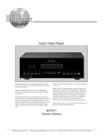
STEP 1.
PREPARING TO INSTALL HEATER
a)
Open carton and carefully remove heater and all additional parts.
b)
Make sure all components illustrated in Figure 1 have been shipped. You should have
received:
1 - Wind-O-Warm Window/Wall Direct Vent Gas Heater
1 - Ball Valve with Flex Connector
2 - Support Brackets
2 - Side Panels
1 - Packing set including (Caulking, Thermostat, Thermostat Wire, Insulated Staples,
Weather Stripping, and Installation and Operating Instructions)
c)
Check rating plate on heater to verify correct model number and type of gas for intended use.
HEATER
FRONT PANEL
INSTALLATION
INSTRUCTIONS
FLEX GAS LINE
WITH SHUTOFF
WEATHER STRIPPING
WINDOW
TRIM (2)
THERMOSTAT WIRE
SUPPORT
BRACKET (2)
THERMOSTAT
STAPLES (10)
CAULKING
FIGURE 1
LOCATION
STEP 2
1.
This heater must be installed through an opening on an outside wall. The heater may be installed in an
existing window or opening cut through a wooden, brick, or masonry wall.
2.
For most efficient performance, locate heater as centrally as possible in the area to be heated.
3.
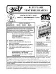
Once a desired location is selected, and before cutting hole, check the outside of the structure for required
clearances to vent exhaust and air intake. See Figure 2.
(Cont’d. on next page. . . )
Page 4
Page 5
*18 Inches (46 cm)
*12 Inches (30 cm)
*12 Inches (30 cm)
*24 Inches (60 cm)
Clearance in accordance with local installation co
requirements of the gas supplier.
Clearance in accordance with local installation co
requirements of the gas supplier.
6 Inches (15 cm) for appliances < 10,000 Btuh (3
for appliances > 10,000 Btuh (3 kw) and < 50,00
inches (30 cm) for appliances > 50,000 Btuh (15
3 Feet (91 cm) above if within 10 feet (3 m) hori
Clearance in accordance with local installation co
requirements of the gas supplier.
Clearance in accordance with local installation co
requirements of the gas supplier.
*18 Inches (46 cm)
*12 Inches (30 cm)
*12 Inches (30 cm)
*24 Inches (60 cm)
3 feet (91 cm) within a height 15 feet (4.5 m) above the meter/regulator
assembly
3 feet (91 cm)
U.S. Installations ²
12 Inches (30 cm)
6 Inches (15 cm) for appliances < 10,000 Btuh (3
for appliances > 10,000 Btuh (3 kw) and < 50,00
inches (30 cm) for appliances > 50,000 Btuh (15
*12 Inches (30 cm) recommended to prevent con
Canadian Installations ¹
12 Inches (30 cm)
6 Inches (15 cm) for appliances < 10,000 Btuh (3 kw), 12 inches (30 cm)
for appliances > 10,000 Btuh (3 kw) and < 100,000 Btuh (30 kw), 36
inches (91 cm) for appliances > 100,000 Btuh (30 kw)
*12 Inches (30 cm) recommended to prevent condensation on window
J = Clearance to nonmechanical air supply inlet to
6 Inches (15 cm) for appliances < 10,000 Btuh (3 kw), 12 inches (30 cm)
building or the combustion air inlet to any other
for appliances > 10,000 Btuh (3 kw) and < 100,000 Btuh (30 kw), 36
appliance
inches 91 cm) for appliances > 100,000 Btuh (30 kw)
K = Clearance to a mechanical air supply inlet
6 Feet (1.83 m)
L = Clearance above paved sidewalk or paved
7 Feet (2.13 m) †
driveway located on public property
M = Clearance under veranda, porch, deck, or
12 Inches (30 cm) ‡
balcony
¹ In accordance with the current CSA B149.1, Natural Gas and Propane Installation Code.
² In accordance with the current ANSI Z223.1/NFPA 54, National Fuel Gas Code.
† A vent shall not terminate directly above a sidewalk or paved driveway that is located between two single family dwellings and serves both dwellings.
‡ Permitted only if veranda, porch, deck, or balcony is fully open on a minimum of two sides beneath the floor.
* For clearances not specified in ANSI Z223.1/NFPA 54 or CSA B149.1, one of the following shall be indicated:
a.) A minimum clearance value determined by testing in accordance with section 4.7.3, 6.5.5, 8.5.5; or;
b.) A reference to the following footnote:
“Clearance in accordance with local installation codes and the requirements of the gas supplier.”
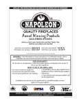
C = Clearance to permanently closed window
D = Vertical clearance to ventilated soffit located
above the terminal within a horizontal distance of
2 feet (61 cm) from the center line of the terminal
E = Clearance to unventilated soffit
F = Clearance to outside corner
G = Clearance to inside corner
H = Clearance to each side of center line extended
above meter/regulator assembly
I = Clearance to service regulator vent outlet
A = Clearance above grade, veranda, porch, deck, or balcony
B = Clearance to window or door that may be opened
AIR SUPPLY INLET
X
AREA WHERE TERMINAL
IS NOT PERMITTED
VENT TERMINAL
V
FIGURE 2. VENT TERMINAL CLEARANCES
LOCATION - Continued
4.
5.
6.
Allow 48” (122 cm) inches from outside rear of cabinet to any obstructions such as fences, walls, shrubs,
trees, etc. (Consider outside appearance, pedestrian traffic walkways, plantings, etc.).
Do not install heater where the exhaust or air intake will terminate in a window well or any opening below
ground level. Special precautions may be required to prevent snow build-up within 12” (30 cm) of the air
intake.
Check required clearances for front panel (See Figure 3).
CLEARANCES
CLEARANCES TO COMBUSTIBLES
COMBUSTIBLE
CLEARANCE
Floor...................................... 6 Inches (15 cm)
Right Side.............................. 12 Inches (30 cm)
Left Side................................ 12 Inches (30 cm)
Back...................................... 48 Inches (122 cm)
Front.................................... 60 Inches (153 cm)
Ceiling.................................... 12 Inches (30 cm)
Draperies Above Heater.......... 4 Inches (10 cm)
Vent........................................ 48 Inches (122 cm)
12” (30 cm)
12”
(30 cm)
12”
(30 cm)
6” (15 cm)
RIGHT SIDE WALL
LEFT SIDE WALL
CEILING
(153 cm)
60”
FRONT OF PANEL
FLOOR
FIGURE 3
7.
8.
9.
10.
11.
Clearances around heater must provide adequate room for service, cleaning and air circulation.
Make sure no electrical wires or water pipes are in stud space selected.
RESIDENTIAL GARAGE INSTALLATION. Gas utilization equipment in residential garages shall
be installed so that all burners and burner ignition devices are located not less than 18 inches {46 cm}
above the floor.
Unit should be located or protected so it is not subject to damage by a moving vehicle. Use care in
selecting a good location within the garage. DO NOT locate the heater where heated air will be
directed onto a nearby parked vehicle, as vehicle paint may discolor or rubber may harden and crack.
DO NOT allow open or closed containers of paint, gasoline or other liquids having flammable vapors to be
stored or used in the same area as the heater.
Gas supply line must be 3/8” minimum. Consult gas supplier, local code agency, or ANSI Z223.1 for
proper sizing and routing of supply line.
Unit must have a grounded 115 v. electrical outlet. Heater is equipped with a 3-prong, 9 ft. factory
installed power cord.
Page 6
STEP 3 - LOCATE THERMOSTAT
1.
2.
3.
4.
5.
Thermostat must be installed in same room as heater.
Locate thermostat on an inside wall approximately 5 feet {153 cm} above the floor and at least 6 feet
{183 cm}from the heater.
Do not locate thermostat so as to be effected by heat from sources other than the heater (i.e. direct
sunlight, lamps, T.V. sets, radiators, registers, etc.).
Do not locate thermostat in unusually cool locations (i.e. outside wall, on a wall separating the heated
area from an unheated area, in drafts from stairwells, doors, windows, etc.).
Install thermostat where there is good air circulation and where it is readily accessible for wiring, service
and adjustment. Never install in a corner, alcove, over or behind furniture or behind a door.
STEP 4 - GAS SUPPLY ROUGH-IN
1.
2.
3.
4.
5.
6.
7.
8.
An inch and a half (1-1/2”) opening is provided toward the right front of the liner bottom for installation
of the gas supply line. This opening facilitates installation of a gas supply line located inside the room
where the heater is installed. If the gas supply line is located in a stud space or other concealed area
consult the gas supplier, local code officials or the latest edition of ANSI Z223.1/NFPA 54 for special
instructions and approval for a concealed gas supply line. NOTE: If gas supply line is concealed, it must
be brought into the room under the heater as there must be a manual shut-off valve installed in the
gas supply line that is accessible from inside the room where the heater is installed.
The valve must be connected only by means of a pipe union of the ground joint type.
Mr. Installer, support gas valve, with a second wrench, when connecting the gas supply line, to prevent
damage.
Install at least 3/8” gas supply line. Contact local gas supplier if any questions.
Install a drip leg in gas supply line immediately upstream from the gas connection to heater. (see local
codes), and provide a 1/8” N.P.T. plugged tapping, accessible for test gauge connection and an individual manual shut off valve accessible within room where heater is installed. (See Figure 4). The heater
and its individual shut off valve must be disconnected from the gas supply piping system during any
pressure testing of that system at test pressures in excess of 1/2 psig (3.5Pa). The heater must be
isolated from the gas supply piping system by closing its individual manual shut off valve during any
pressure testing of the gas supply piping system at test pressures equal to or less than 1/2 psig (3.5Pa).
Test all connections for leaks using a soapy solution. NEVER USE AN OPEN FLAME TO TEST
FOR LEAKS.
The maximum inlet gas supply pressure for natural or L.P./Propane gas is 1/2 p.s.i. or 14” w.c.
The minimum inlet gas supply pressure for the purpose of adjustment is 4.5” w.c. for natural gas or
11.0” w.c. for L.P./Propane gas.
GAS SUPPLY FROM
CRAWL SPACE
Outside Wall
GAS SUPPLY
INSIDE ROOM
WITH HEATER
GAS SUPPLY THROUGH
OUTSIDE WALL
Outside Wall
WOW Heater
WOW Heater
WOW Heater
Manual shut
off valve must
be in room with
heater
Manual shut off
valve must be in
room with heater
Manual shut off valve must
be in room with heater
Floor
Gas Supply
FIGURE 4
Drip
Leg
Gas Supply
Drip
Leg
Drip
Leg
Floor
Gas Supply
Floor
NOTE: 1/8” NPT plugged tapping must be provided in gas
supply line immediately ahead of the heater. This tapping may
be in the manual cutoff valve or in a separate fitting.
Page 7
STEP 5 - INSTALLING THE HEATER
Use only factory supplied parts. Do not modify heater in any way.
WINDOW INSTALLATION
A.)
B.)
C.)
Raise window - locate center.
Heater requires level mounting surface,
framing may be necessary in window sill.
Remove the 6 screws securing the back
of outer cabinet to intake and exhaust
tube flange and save (See Figure 5).
E.)
Center outer cabinet in window opening
and slide in so bottom flange is flush
against windowsill. Secure cabinet to
windowsill through holes provided in
cabinet bottom. Use appropriate fasteners
(not provided) for type of material you
are securing into. (See Figure 7).
FIGURE 5
D.)
Gently slide combustion tube assembly
forward and out of the outer casing
assembly (See Figure 6).
WOW253 /
WOW254
FIGURE 7
F.)
G.)
WOW403 /
WOW404
FIGURE 6
Page 8
Lower window onto the outer cabinet top.
Do not apply excessive downward force
as the cabinet top could be damaged.
Leave a minimum 1/16” gap between front
of window sash and cabinet top flange.
This gap is required to install the front
panel. Locate and drill three holes through
the cabinet top into the center of the
window sash. Use appropriate fasteners
(not provided) for type of material you are
securing into.
Precisely measure the remaining opening
on each side of cabinet and cut side trim
panels (provided) to fit. Affix weather
stripping on three sides.
WINDOW INSTALLATION - Cont’d.
H.)
Using 3 #8 x 3/8” screws (provided), attach trim
panels to left and right flanges on outer cabinet.
The 1/2”, 90 degree break on the trim panel
must be attached securely to the window frame.
(See Figure 8).
K.)
L.)
M.)
N.)
FIGURE 8
I.)
J.)
From outside secure the two support brackets
to the outside wall, anchors (not provided) may
be required. Make sure brackets are flush
against the outer cabinet bottom and under the
left and right sides. You must drill four 7/64”
holes through the outer cabinet bottom using
clearance holes in the support bracket as a
template. Secure bracket to outer cabinet
bottom using four #8x1/2” screws provided.
See Figure 21.
Gently slide the combustion tube assembly back
into outer cabinet. Make sure air intake and
exhaust tubes extend through holes in outer
cabinet back. From the outside, secure the
cabinet back to the tube flanges with the screws
removed in Step C. Make sure flange gaskets
are in place (See Figure 5).
O.)
Locate factory installed thermostat wires
extending from the front of heater.
Connect 24 V. wall thermostat (provided) to heater using a maximum 20’ of
thermostat wire. Do not splice thermostat wire. (See Figure 9).
Connect 3/8” minimum gas supply line
to heater. (See Figure 4).
Plug factory wired power cord into a
properly grounded 115 volt electrical
outlet. NEVER use an extension cord.
If homeowner desires, heater may be
hard wired by a licensed electrician
(check your local electrical codes).
Turn gas supply on, check all connections for leaks using a soapy solution.
NEVER check for leaks with an open
flame.
Install front panel. Hang top of front
panel over top cabinet flange and
between window sash. Secure using
four (4) #8 x 1/2” painted screws (Provided). (See Figure 10).
FIGURE 10
O.)
From outside, caulk between cabinet
and side panels.
INSTALLATION IS NOW COMPLETE. FOLLOW LIGHTING INSTRUCTIONS TO PUT
HEATER IN OPERATION.
THERMOSTAT
WIRE
FIGURE 9
Page 9
DURING INITIAL WARM-UP HEATER MAY
SMOKE SLIGHTLY, SO PROVISION
SHOULD BE MADE FOR ADEQUATE VENTILATION.
INSTALLING THROUGH A FRAME WALL
NOTE: The WOW25 models will install between wall studs on 16” centers. The WOW40 will attach to a stud
on either the right or left side. The opposite stud must be cut out of the opening and 1-1/2” below the cutout. You
must then install a 2”-by your wall thickness plate on top of the cut stud and secure to the remaining stud. This plate
will cover the opening inside the wall, front to back, and provides support as well as a foundation that will be used
to secure the bottom of the heater.
G.)
Secure in place through side of cabinet into
A.)
At desired height, mark hole opening for your
stud. WOW253/254 will be secured into
model heater. (See Figure 11).
studs on both sides. WOW403/404 must
be secured to stud on one side, can be left
A.) WOW40 - 25-1/8”
or right side. (See Figure 12).
A.) WOW25 - 14-3/8”
H.)
From outside secure the two support brackets to the outside wall, anchors (not provided)
may be required. Make sure brackets are
flush against the outer cabinet bottom and under the left and right sides. You must drill four
7/64” holes through the outer cabinet bottom
17 1/4”
using clearance holes in the support bracket
as a template. Secure brackets to outer
cabinet bottom using four #8x1/2” screws
provided. See Figure 21.
I.)
Gently slide combustion tube assembly back
FIGURE 11
into outer cabinet. Check to make sure the
gaskets on the intake and exhaust tube
B.)
Before cutting, verify both inside and outside
flanges are in place and unbroken. Flanges
clearances. Verify that no electrical wires, conmust be flush against back of outer cabinet.
duit, water or gas pipes pass through the area
From outside, secure back of outer cabinet
you have marked.
to air intake and exhaust flanges with the
C.)
Cut out marked hole location. Make sure that
six (6) screws removed in step D.
the cut out opening is level inside to outside.
J.)
Locate factory installed thermostat wires
D.)
Remove six (6) screws from back of heater
extending from the front of heater. Connect
which secure back of outer cabinet to intake
24 V. wall thermostat (provided) and a maxiand exhaust tube flanges. Save screws. (See
mum 20’ of thermostat wire. Do not splice
Figure 5).
thermostat wire. (See Figure 9).
E.)
Gently slide combustion tube assembly forK.)
Connect 3/8” minimum gas supply line to
ward and out of outer cabinet. (See Figure 6).
heater. (See Figure 4).
F.)
From inside the room, slide outer cabinet
L.)
Plug factory wired power cord into a properly
through cut out opening until flanges are flush
grounded 115 volt electrical outlet. Never use
against inside wall. (See Figure 12).
an extension cord. If homeowner desires,
heater may be hard wired by a licensed electriWOW 25
WOW 40
cian (check your local electrical codes).
M.)
Turn gas supply on. Check all connections
WALL
WALL
for leaks using a soapy solution. NEVER
STUD
STUD
check for leaks with an open flame.
N.)
Install front panel. Hang top of front panel
over top outer cabinet flange and between
wall. Secure using four (4) #8 x 1/2 painted
screws (provided). (See figure 10).
M
u
s
t
M u s t One stud
install
must
be
O.)
From
outside, caulk between cabinet and wall
install
base
b a s e cut
opening.
Installation is now complete. Follow
plate
plate
lighting instructions to put heater in operation.
During initial warm-up heater may smoke
slightly, so provision should be made for adFIGURE 12
equate ventilation.
Page 10
INSTALLING THROUGH A MASONRY WALL
A.)
B.)
C.)
D.)
E.)
F.)
G.)
H.)
I.)
J.)
K.)
At desired height, mark hole opening for your
model heater. (See Figure 11).
Before cutting, verify both inside and outside
clearances. Verify that no electrical wires, conduit, water or gas pipes pass through area you
have marked.
Cut out marked hole location. Make sure that
cut out opening is level inside to outside.
Remove six (6) screws from back of heater
which secure back of outer cabinet to intake
and exhaust tube flanges. Save screws. (See
Figure 5).
Gently slide combustion tube assembly forward
and out of outer cabinet. (See Figure 6).
From inside the room, slide outer cabinet
through cut out opening until side and bottom
flanges are flush against inside wall. (See Fig
ure 12). This leaves a 1/16” gap between the
wall and cabint top flange. This gap is necessary to install the front panel.
Secure in place using holes in side of outer
casing. Use fasteners appropriate for type of
wall material. Anchors (not provided) may be
required.
From outside secure the two support brackets
to the outside wall, anchors (not provided) may
be required. Make sure brackets are flush
against the outer cabinet bottom and under the
left and right sides. You must drill four 7/64”
holes through the outer cabinet bottom using
clearance holes in the support bracket as a template. Secure brackets to outer cabinet bottom using four #8x1/2” screws provided. See
Figure 21.
Gently slide combustion tube assembly into
outer cabinet. Check to make sure the
gaskets and the intake and exhaust tube flanges
are in place and unbroken. Flanges must be
flush against back of outer cabinet. From
outside, secure back of outer cabinet to air
intake and exhaust flanges with the six (6)
screws removed in Step D.
Locate factory installed thermostat wires
extending from the front of heater. Connect
24 V. wall thermostat (provided) using 20’
maximum thermostat wire. Do not splice
thermostat wire. (See Figure 9).
Connect 3/8” minimum gas supply line to
heater. (See Figure 4).
Page 11
L.)
M.)
N.)
O.)
Plug factory wired power cord into a
properly grounded 115 volt electrical
outlet. NEVER use an extension cord. If
homeowner desires, heater may be
hardwired by a licensed electrician (check
your local electrical codes).
Turn gas supply on. Check all connections
for leaks using a soapy solution. NEVER
check for leaks with an open flame.
Install front panel. Hang top of front panel
over top outer cabinet flange and between
wall. Secure using four (4) #8 x 1/2” painted
screws (provided). (See Figure 10).
From outside, caulk between outer cabinet
and wall opening.
Outside Wall
Outer Cabinet
Outer
Cabinet
Support
Bracket
#8x1/2 Screw
Support
Brackets
Figure 21
INSTALLATION IS NOW COMPLETE.
FOLLOW LIGHTING INSTRUCTIONS TO
PUT HEATER INTO OPERATION.
DURING INITIAL WARM-UP HEATER MAY
SMOKE SLIGHTLY, SO PROVISION
SHOULD BE MADE FOR ADEQUATE VENTILATION.
FOR YOUR SAFETY READ BEFORE OPERATING
WARNING: If you do not follow these instructions exactly, a fire or explosion may result
causing property damage, personal injury or loss of life.
A.
B.
This appliance does not have a pilot. It is
equipped with an ignition device which
automatically lights the burner. Do not try
to light the burner by hand.
• If you cannot reach your gas supplier, call
the fire department.
C.
Use only your hand to push in or turn the gas
control knob. Never use tools. If the knob will
not push in or turn by hand, don’t try to repair
it, call a qualified service technician. Force or
attempted repair may result in a fire or explosion.
D.
Do not use this appliance if any part has been
under water. Immediately call a qualified service
technician to inspect the appliance and to
replace any part of the control system and any
gas control which has been under water.
BEFORE OPERATING smell all around the
appliance area for gas. Be sure to smell next
to the floor because some gas is heavier than
air and will settle on the floor.
WHAT TO DO IF YOU SMELL GAS:
• Do not try to light any appliance.
• Do not touch any electric switch; do not
use any phone in your building.
• Immediately call your gas supplier from a
neighbor’s phone. Follow the gas supplier’s
instructions.
OPERATING INSTRUCTIONS
1.
2.
3.
4.
5.
6.
7.
8.
9.
10.
STOP! Read safety information on this label.
Set the thermostat to the lowest setting.
Turn off all electric power to the appliance.
This appliance is equipped with an ignition device which automatically lights the burner. Do not try to light the burner
by hand.
Turn gas control knob clockwise
to “OFF”. Do not force.
Wait five (5) minutes to clear out any gas. If you smell gas, STOP! Follow “B” in safety information on this label. If
you don’t smell gas, go to next step.
Turn gas control knob counterclockwise
to “ON”.
Turn on all electric power to the appliance.
Set thermostat to desired setting.
If the appliance does not operate, follow instructions “To Turn Off Gas To Appliance” and call your service technician
or gas supplier.
Gas control knob shown
in “OFF” position
TO TURN OFF GAS TO APPLIANCE
1.
2.
3.
Set the thermostat to lowest setting.
Turn off all electric power to the appliance if service is to be performed.
to “OFF”. Do not force.
Turn gas control knob clockwise
Page 12
PROPER BURNER FLAME
Appliance input ratings are based on sea level operation and need not be changed for operation up to 2,000 (609.9m)
elevation. For operation at elevations above 2,000 ft. (609.9m), manufactured to specified deration conditions for
Canada and the United States, use the following orifice chart for/to determine the correct orifice DMS for a specific
elevation.
BURNER
BOX
SIGHT GLASS
MANIFOLD
BURNER
BOX
SIGHT
GLASS
GAS
VALVE
FIGURE 13 - - WOW403 / WOW404
FIGURE 13 - - WOW253 / WOW254
LIGHT BLUE OUTER MANTLE
FIGURE 14
DARKER BLUE INNER MANTLE
There is no primary air adjustment on the burner and with correct installation, a proper flame is assured; since the
correct manifold pressure and orificing has been done at the factory for elevations up to 2,000 ft.
HIGH ALTITUDE BURNER
ORIFICING
Appliance input ratings are based on sea level operation
and need not be changed for operation up to 2,000 ft.
(609.9m) elevation. For operation at elevations bove 2,000
ft. (609.9m), manufactured to specified deration conditions for Canada and the United States. Use the following orifice chart for/to determine the correct orifice DMS
for a specific elevation.
SPECIFIC ELEVATIONS
MODEL
NO.
0 to
2,000’
WOW253
WOW403
1.3
54
WOW254
WOW404
67
66
2,000’
4,000’
4,000’
6,000’
6,000’
8,000’
8,000’ 10,000’
56
56
57
56
70
69
70
70
NATURAL GAS
55
55
56
55
L.P. GAS
68
68
69
68
After conversion is complete, attach P/N 91137 Label
adjacent to the rating plate.
Page 13
BLOCKED VENT SHUT-OFF
SYSTEM
This heater is equipped with a blocked vent shutoff system that will automatically turn the heater
off in the advent of the vent exhaust or air intake
pipe becoming blocked. This blockage may be
caused by snow accumulation, insects, small animals, animal nest, etc.
Once this occurs the heater will remain in a lockout cycle for one hour. After one hour there will
be an ignition attempt. If the blockage has been
removed, the heater will return to normal operation. If the blockage remains, the heater will return to a one hour lock out cycle.
If this problem occurs, homeowners must not attempt to operate or repair the heater themselves
but contact a qualfied service agency.
GAS CONVERSION
CONVERTING GAS CONTROL
This heater is field convertible. Use only factory supplied, certified kits.
A.)
Model
Number
WOW253
WOW254
Conversion
Description
Kit No.
Convert Nat. to L.P. 20,000 49670
Convert L.P. to Nat. 20,000 49660
B.)
WOW403
WOW404
Convert Nat. to L.P. 40,000
Convert L.P. to Nat. 40,000
49690
49680
CAUTION: Only qualified installers or service
agency are authorized to make a gas conversion on this heater.
C.)
D.)
“NAT” ON TOP FOR
NATURAL GAS
ORIFICE CONVERSION
A.)
B.)
C.)
D.)
E.)
F.)
G.)
H.)
I.)
J.)
K.)
L.)
M.)
N.)
Remove the converting seal cap. (See
Figure A). WARNING: Do not remove or
tamper with any other valve components.
Remove the black rubber gasket from the
down side of the converting seal cap and
reinstall gasket on opposite side of
converting seal cap. Gasket must be on
down (valve) side of converting seal cap.
(See Figure A).
Invert the converting seal cap and reinstall.
Insure that the desired gas (LP for liquefied
petroleum or NAT for natural gas) symbol
is visible after reassembly of cap.
(See Figure A).
Turn thermostat to “OFF” or lowest setting.
Allow heater to cool. Remove front panel.
Turn off electric power to heater.
Turn off gas supply.
Disconnect gas supply line from gas control.
From outside, remove six (6) screws securing back of outer cabinet to air intake and
exhaust flanges.
From inside, gently slide combustion tube
assembly forward and out of outer cabinet.
Disconnect gas control wires and remove
right side of inner cabinet.
Remove two screws securing gas control
bracket to burner box.
Remove six (6) screws securing manifold
to burner box.
Pull manifold/gas control assembly out of
burner box.
Replace burner orifices with orifices of correct size for type of gas and elevation. NOTE:
The WOW403, 404 requires 5 orifices and
the WOW253, 254 requires 3.
Carefully check integrity of all gaskets, make
sure all gaskets are in place.
Re-assemble heater by reversing Steps K F.
“LP” ON TOP FOR
L.P. GAS
CONVERTING SEAL
CAP SEE A-A
GASKET
MAXITROL
GAS VALVE
FIGURE A
COMPLETING CONVERSION
A.)
B.)
C.)
D.)
E.)
F.)
Page 14
Connect gas supply line to gas control.
Turn on gas supply. Check for leaks using
a soapy solution. NEVER use an open
flame to check for leaks.
Turn on electric power to heater.
Replace front panel.
Follow lighting instructions to place heater
in operation.
Using a Manometer, check manifold pressure. Correct pressure is 3.5” w.c. for
Natural and 10.0” w.c. for L.P..
WIRING
IF ANY OF THE ORIGINAL WIRE AS SUPPLIED WITH THE APPLIANCE MUST BE REPLACED, IT
MUST BE REPLACED WITH A WIRE OF AT LEAST 105 DEGREE C TEMPERATURE RATING.
CAUTION: LABEL ALL WIRES PRIOR TO DISCONNECTION WHEN SERVICING CONTROLS. WIRING ERRORS CAN CAUSE IMPROPER AND DANGEROUS OPERATION.
VERIFY PROPER OPERATION AFTER SERVICING.
WIRING DIAGRAM - WOW253 & WOW254
Pressure
Switch
Red
Red
White
Purple
Gas
Valve
Orange
Thermostat
Black
Black
Blue
R
Yellow
Limit
Switch
G
Draft
Inducer
W C
CMB Blower
L1
ACC Brown
Ground
24 V AC8 COOL
WOW253,
WOW254
PICTORIAL
Pressure
Switch
Limit Switch
Thermostat
24 VAC
Circulating
Blower
Circuit Board
24
VAC
Gas Valve
WOW253,
WOW254
LADDER
CIRCUIT BOARD
Transformer
Black
115 VAC
Black
Black
Green
Draft Inducer
Circulating
Blower
WIRING DIAGRAM - WOW403 & WOW404
Thermostat
Purple
Red
White
Black
Pressure
Switch
Gas
Valve
Red
Yellow
Orange
Black
Blue
R
W
Ground
Gas Valve
Pressure
Switch
Limit Switch
Draft Inducer
C
CMB Blower
Limit
Switch
24
VAC
G
WOW403,
WOW404
LADDER
L1 Brown
ACC Gray
24 V
Circuit Board
Thermostat
24 VAC
Circulating
Blower #1
Circulating
Blower #2
CIRCUIT BOARD
115 VAC
Draft Inducer
Transformer
Green
Black
Black
Black
Ignitor
Circulating
Blower #1
WOW403,WOW404
PICTORIAL
P/N 91466 08/2005
Page 15
Circulating
Blower #2
P/N 91467 08/2005
!
Thermostat
calls for
heat
Inducer
continues to
run
!
Pressure
switch
closes
inducer
proved
!
!
YES
!
NO
Pressure switch
closes proving
inducer
Spark
ignition
energized
!
One Hour
Lock Out
!
Gas
valve
opens
gas
flow to
burner
!
Burner
flame
proved
15 Sec.
inter
purge
Page 16
!
YES
Blower
on
!
Heat
cycle
!
Thermostat
satisfied
!
Gas
valve
closes
gas flow
to burners
off
!
Draft
inducer
off
30 Sec.
!
Blower
off
180 Sec.
!
NOTE: IF THERE IS A MALFUNCTION IN STEPS 3, 5, 6 THE OPERATION SEQUENCE WILL STOP AT THAT
POINT. FOR STEPS 5 OR 6, IF AFTER 2 ADDITIONAL ATTEMPTS MALFUNCTION STILL OCCURS, THE CONTROL WILL LOCK OUT FOR ONE HOUR. FOR PURPOSE OF TESTING, THE ONE HOUR LOCKOUT CAN BE
OVERRIDDEN BY RESETTING THE THERMOSTAT OR INTERRUPTING THE ELECTRICAL POWER.
NO
3 Attempts
for ignition
!
STEP #
1)
Thermostat calls for heat.
2)
Draft Inducer turns on.
3)
Pressure switch closes.
4)
Spark ignition begins.
5)
Gas flow to burner.
6)
Burner ignition proven.
7)
Circulating Blower on.
8)
Heater burns through heating cycle.
9)
Thermostat satisfied.
10)
Gas flow off to burner.
11)
Draft inducer off.
12)
Circulating Blowers off.
13)
Heater in stand-by.
!
Power
on to
draft
inducer
!
90 Sec.
!
Heater
in
standby
NO
YES
!
YES
4 Sec.
!
!
WIND-O-WARM SEQUENCE OF OPERATION
NO
Heater
in
standby
MAINTENANCE INSTRUCTIONS
■
For correct and safe operation, keep heater and heater area clean. At regular intervals, turn control valve
to OFF, let heater cool and clean inside control and heat exchanger compartments.
■
To clean outside cover, use a damp cloth, do not use any kind of solvent or cleaning fluid as they may leave
a residue that could burn or give off odors when heater is turned on.
■
Have heater, including exhaust/intake tubes, checked, cleaned and/or repaired by a qualified service person
prior to use each year.
■
Follow a regular service and maintenance schedule for safe and efficient operation.
■
Do not obstruct combustion, ventilation or circulating air.
■
Do not place furniture in front of heater.
■
Keep bushes, shrubs, etc. trimmed to maintain a 12” clearance below and 48” from back of heater.
■
If any components are removed, make sure all gaskets are reinstalled and are in good condition. If any
sign of damage, replace gasket as this is a sealed system and must be air-tight for proper operation. DO
NOT operate heater with any gasket missing or damaged. Failure to replace a missing or damaged gasket
may result in property damage, personal injury, loss of life, or poor performance.
SERVICE RECORD
SERVICE RECORD
DATE
DATE
DATE
DATE
Page 17
DATE
DATE
TO REMOVE MAIN BURNERS FOR INSPECTION AND CLEANING:
SERVICE MUST BE PERFORMED BY A QUALIFIED SERVICE AGENCY
INSTRUCTIONS FOR WOW253 & WOW254
A.)
B.)
C.)
D.)
E.)
F.)
G.)
H.)
I.)
J.)
K.)
L.)
Turn thermostat to “OFF” or lowest setting.
Allow heater to cool.
Turn off electric power to the heater.
Turn off the gas supply.
Remove front panel.
Disconnect ignition cable and pressure switch tubing from burner box bottom.
Remove fourteen screws securing burner box bottom.
Remove two screws that secure each burner to burner mounting bracket. See Figure 17.
Slide burner forward, down and out of burner box.
You can now inspect, clean or replace burner
as needed. Clean by blowing compressed air
through burner. Special care must be taken
not to damage the ceramic burner head or
enlarge the ports.
Carefully check integrity of the burner box
bottom gasket, replace if damaged.
Reinstall by reversing steps J through A.
Follow lighting instructions to place heater in
operation.
Model WOW403/WOW404 shown
FIGURE 15
WOW253 / WOW254 MODELS HAVE THREE BURNERS
WOW403 / WOW404 MODELS HAVE FIVE BURNERS
FIGURE 17
Page 18
TO REMOVE MAIN BURNERS FOR INSPECTION AND CLEANING:
SERVICE MUST BE PERFORMED BY A QUALIFIED SERVICE AGENCY
INSTRUCTIONS FOR WOW403 & WOW404
A.)
B.)
C.)
D.)
E.)
F.)
G.)
H.)
I.)
J.)
K.)
L.)
Turn thermostat to “OFF” or lowest setting.
Turn off electric power to heater.
Allow heater to cool.
Turn off gas supply.
Disconnect gas supply line at heater.
Remove front panel.
From outside, remove six (6) screws securing
back of outer cabinet to air intake and exhaust
flanges. (See Figure 5).
From inside, gently slide combustion tube as
sembly forward and out of outer cabinet. (See
Figure 6).
Disconnect valve wires and remove right side
of inner cabinet. (See Figure 15).
Disconnect ignition cable and pressure switch
tubing from top of burner box. Remove screws
securing burner box topand lift top off of burner
box.
Remove two screws that secure each burner to
burner mounting bracket. (See Figure 17).
Once screws are removed, slide burner forward
slightly off of burner orifice and lift up.
M.)
N.)
You can now inspect, clean or replace
burner as needed. Clean by blowing compressed air through burner. Special care
must be taken not to damage ceramic head
of burner, or enlarge the burner ports in
the ceramic head.
Carefully check integrity of burner box top
gasket, then reinstall by reversing steps K A. Follow lighting instructions to put heater
in operation.
FIGURE 15
WOW403 / WOW404 MODELS HAVE FIVE BURNERS
FIGURE 17
Page 19
TO REMOVE COMBUSTION TUBE ASSEMBLY FOR
INSPECTION, CLEANING AND REPLACEMENT
SERVICE MUST BE PERFORMED BY A
QUALIFIED SERVICE AGENCY.
A.)
B.)
C.)
D.)
E.)
F.)
G.)
H.)
I.)
J.)
K.)
L.)
M.)
N.)
For WOW253 / WOW254
Turn thermostat to “OFF” or lowest setting.
Allow heater to cool.
PRESSURE
IGNITOR
SWITCH
Turn off electric power to heater..
CABLE
TUBING
Turn gas supply valve to “OFF”.
Disconnect gas supply line from gas valve.
From outside, remove six (6) screws
securing back of outer cabinet to air in
take and exhaust flanges. (See Figure 5).
From inside, gently slide combustion tube
BURNER
IGNITOR
BOX
assembly forward and out of outer
cabinet. (See Figure 6).
Disconnect air pressure switch tubing from draft
inducer. See Figure 18-A.
Remove draft inducer. (See Figure 18-A).
Disconnect ignition cable and pressure
FIGURE 16
switch tubing from top of burner box.
(See Figure 16).
JUNCTION BOX
TRANSFORMER
Remove screws securing collection box and
AIR INTAKE
burner box flange to liner top, bottom, left side,
right side and back. (See Figure 19).
Pull combustion tube assembly forward
CIRCULATING
BLOWER #1
and out of the liner. (See Figure 20).
CIRCUIT
BOARD
You can now inspect, clean or replace
tubular heat exchanger as needed. NOTE: If
combustion tube assembly is being replaced,
you must keep and use collection and burner
LINER
box from assembly being replaced.
PRESSURE
Carefully check integrity of all gaskets (replace
SWITCH
as needed), then reinstall combustion tube
assembly by reversing Steps L - A.
DRAFT INDUCER
Follow lighting instructions to put heater
FIGURE 18-A (For WOW253 / WOW254)
in operation.
FIGURE 19
Page 20
FIGURE 20
TO REMOVE COMBUSTION TUBE ASSEMBLY FOR
INSPECTION, CLEANING AND REPLACEMENT
SERVICE MUST BE PERFORMED BY A
QUALIFIED SERVICE AGENCY.
A.)
B.)
C.)
D.)
E.)
F.)
G.)
H.)
I.)
J.)
K.)
L.)
M.)
N.)
For WOW403 / WOW404
Turn thermostat to “OFF” or lowest
setting. Allow heater to cool.
PRESSURE
IGNITOR
Turn off electric power to heater.
SWITCH
CABLE
Remove front panel.
TUBING
Turn gas supply valve to “OFF”.
Disconnect gas supply line from gas valve.
From outside, remove six (6) screws
securing back of outer cabinet to air in
take and exhaust flanges. (See Figure 5).
BURNER
IGNITOR
From inside, gently slide combustion tube
BOX
assembly forward and out of outer
cabinet. (See Figure 6).
Disconnect air pressure switch tubing
from draft inducer. (See Figure 18-B).
Remove draft inducer. (See Figure 18-B).
Disconnect ignition cable and pressure
FIGURE 16
switch tubing from top of burner box.
(See Figure 16).
Remove screws securing collection box
Circulating
Blower #2
flange and burner box flange to inner
Draft
Inducer
casing top, bottom, and back.
Circuit
(See Figure 19).
Board
Pull combustion tube assembly forward
Transformer
Liner
and out. (See Figure 20).
You can now inspect, clean or replace
Junction
Circulating
tubular heat exchanger as needed.
Box
Blower #1
NOTE: If combustion tube assembly is
Air
Intake
being replaced, you must keep and use
Pressure
collection box and burner box from
Switch
assembly being replaced.
Carefully check integrity of all gaskets
FIGURE 18-B (For WOW403 / WOW404)
(replace as needed), then reinstall combustion
tube assembly by reversing Steps L - A.
Follow lighting instructions to put heater in
operation.
FIGURE 19
Page 21
FIGURE 20
TROUBLE SHOOTING CHART
To assist in diagnosing and servicing, this heater is equipped with a self-diagnosing control module. Should a
malfunction occur, the green indicator light on the control module will flash a varying number of times indicating the
circuit in which malfunction is located.
# OF
FLASHES
REASON FOR
INDICATION
Slow Flash
Normal operation,
no call for heat
Fast Flash
Normal operation,
call for heat
POSSIBLE CAUSES
CORRECTIVE ACTION
2
System lockout
failed to detect or
sustain flame
a.) Defective ignitor.
a.) Replace ignitor.
b.) Ignition cable defective.
b.) Replace ignitor cable.
c.) Ignitor cable disconnected.
c.) Connect ignitor cable.
d.) Manual gas valve in “OFF”
d.) Turn manual gas valve to “ON”.
position. No gas to valve.
e.) Defective wire to gas valve.
e.) Replace defective wire.
f.) Wire to gas valve disconnected. f.) Connect gas valve wire.
g.) Obstruction to vent outlet.
g.) Remove obstruction.
h.) Obstruction to air inlet.
h.) Remove obstruction.
3
Pressure switch
Open or Closed
a.) Defective pressure switch.
b.) Pressure switch tubing
damaged, kinked or collapsed.
c.) Pressure switch tubing
disconnected.
d.) Defective draft inducer.
e.) Pressure switch tubing to
wrong connection.
a.) Replace pressure switch.
b.) Replace damaged tubing.
c.) Connect pressure switch tubing.
d.) Replace draft inducer.
e.) Reverse tubing connections on
pressure switch.
4
Limit Switch opens
a.) Defective limit switch.
a.) Replace limit switch.
b.) Damaged limit switch wire.
b.) Replace damaged wire.
c.) Limit switch wire disconnected. c.) Connect limit switch wire.
d.) Blockage in front of front panel. d.) Remove blockage.
e.) Heater over rate.
e.) Check orifice, pressures, rate.
5
Flame sensed gas
valve not energized
a.) Defective gas valve.
b.) Defective control module.
a.) Replace gas valve.
b.) Replace control module.
Steady light
No Flashes
Internal failure
(control module
failure and power
on self-check)
a.) Defective control module.
a.) Replace control module.
Page 22
TROUBLE SHOOTING CHART
SYMPTOM
POSSIBLE CAUSES
Flame too large
1. Defective operator section of valve.
2. Burner orifices too large.
Yellow burner flame
Gas odor
Delayed Ignition
Failure to ignite
Burner won’t turn off
CORRECTIVE ACTION
3. If installed above 2,000 ft.
1. Clogged burner ports.
2. Obstruction around air intake or.
exhaust tubes.
1. Gas leak.
1. Low gas pressure.
2. Ignitor not properly located.
1. Main gas off.
2. Thermostat not set high enough to call
for heat.
3. Clogged burner orifice.
4. Incorrect wiring.
5. Defective valve.
6. No power to unit.
7. Defective pressure switch.
1. Defective or damaged thermostat wire,
or thermostat.
2. Thermostat location.
Incorrect gas input
Not enough heat
Too much heat
Main burner goes out
during normal operation
3.
4.
5.
6.
1.
2.
Defective or sticking valve.
Excessive gas pressure.
Defective or damaged thermostat.
Defective gas valve.
Gas input not checked.
Clogged orifice.
1. Furnace undersized.
2.
3.
1.
2.
1.
2.
3.
4.
Temperature set too low.
Low supply pressure.
Temperature dial set too high.
Gas control valve stuck open.
Defective flame sensor.
Input too high.
Defective gasket.
Missing gasket.
5. Limit switch opens.
6. Exhaust or air intake tubes blocked.
Page 23
1. Replace valve.
2. See installation instructions or
check with local gas company for proper
orifice size and replace as needed.
3. See burner orifice section, Page 13.
1. Remove burners and check for
obstructions in throats, ports, and
orifices. Clean - but do not enlarge ports
or orifices.
2. Remove obstruction.
1. See Page 1.
1. Check gas supply pressure.
2. Check ignitor location and correct if
necessary.
1. Open all manual gas valves.
2. Set thermostat to higher temperature.
3. Clean burner orifice (do not enlarge).
4. Check wiring diagram.
5. Replace valve.
6. Check power supply.
7. Replace pressure switch.
1. Can be checked by removing wire from
control board terminal. If burner goes off,
replace thermostat.
2. Re-locate thermostat out of drafts, hot, or
cold spots.
3. Replace valve.
4. Contact utility supplying gas.
5. Replace thermostat.
6. Replace gas valve.
1. Re-check gas input.
2. Clean orifices with a smooth wood
toothpick, do not enlarge.
1. This is especially true when a dwelling
or room is enlarged. Have the heat loss
calculated and compare to furnace
output. Your gas company can supply
you with this information.
2. Raise thermostat setting.
3. Check supply pressure.
1. Lower thermostat setting.
2. Replace gas control valve.
1. Check voltage and replace ignitor if low.
2. Check input rate.
3. Check and replace gasket if needed.
4. Be sure all gaskets are in place and
properly sealed.
5. Check rate - remove any obstructions to
circulating air.
6. Remove obstruction. Check for snow
accumulation blocking intake and/or
exhaust tube.
MODEL NUMBERS
NAT. GAS L.P. GAS
WOW253
WOW254
FAN-TYPE, DIRECT-VENT
THROUGH-THE-WALL GAS HEATER
Prices and specifications subject to change without notice. All prices are F.O.B. factory.
WOW253/
WOW254
Mr. Contractor, we only sell parts through our wholesalers, but the prices listed are for your convenience. For prompt parts
service, contact the wholesaler from which you purchased your Cozy heater. NOTE: Parts prices & schematic drawings on
current models are shown at www.cozyheaters.com.
Page 24
HOW TO PROPERLY ORDER PARTS: In addition to part description and part number, please give model number, serial
number, and type of gas used. This information can be found on the rating plate located inside the cabinet cover.
MODEL NUMBER
MODEL NUMBER
NAT.
L.P.
PART DESCRIPTION
Manifold
Manifold Gasket
Gas Valve, Natural Gas
Gas Valve, L.P. Gas
Burner Orifice, Natural Gas
Burner Orifice, L.P. Gas
Ignitor Cable
Ignitor
Burner Box Bottom
Burner Box Bottom Gasket
Burner
Burner Box
Inlet/Outlet Flange Gasket
Burner/Collection Box Gasket
Sight Glass Gasket
Sight Glass Assembly
Flex Gas Line/Manual Cutoff
Front Panel Assembly
Heat Exchanger
Collection Box
Liner/Collection Box Gasket
Liner, Left Side Extension
Liner, Base Assembly
Liner, Left Side Assembly
Liner, Right Side Assembly
Limit Switch
Liner, Top
Draft Inducer Mounting Plate Gasket
Draft Inducer Mounting Plate Gasket
Draft Inducer Gasket
Draft Inducer
Circulating Blower Gasket
Circulating Blower Mounting Bracket Assy.
Circulating Blower
Pressure Switch Mounting Bracket
Pressure Switch
Junction Box
Terminal Board
Transformer
Circuit Board Mounting Bracket
Circuit Board
Casing Base
Casing Wrapper
Casing Back Assembly
Back Cover Plate Gasket
Back Cover Plate Gasket
Caulking
9' Power Cord
Weatherstripping
Wiring Harness
20' Thermostat Wire
Thermostat 24V
Mounting Support Brackets
Window Enclosure Panels Set/2
REF.
NO.
1
2
3
3
4
4
5
6
7
8
9
10
11
12
13
14
15
16
17
18
19
20
21
22
23
24
25
26
27
28
29
30
31
32
33
34
35
36
37
38
39
40
41
42
43
44
N/A
N/A
N/A
N/A
N/A
N/A
N/A
N/A
WOW253
WOW254
PART
NO.
64501
64665
64590
64591
64509**
64508**
64210
64009
20270
64662
64515**
20240
64655***
64652
64664
20275
64072
20020
64503
20185
64660
N/A
LIST
PRICE
64517
64653
20170
64654
64511
64658
20150
64531
N/A
64594
78059
64596
78069
20175
64625
20075
20070
20045
64659
20060
70151
64205
64657
64669
74518
78355
20355
20860
Mr. Contractor, we only sell parts through our wholesalers, but the prices listed above are for your convenience. For prompt
parts service, contact the wholesaler from which you purchased your Cozy heater. NOTE: Parts prices & schematic drawings
on current models are shown at www.cozyheaters.com.
Page 25
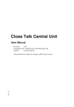
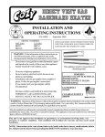
FAN-TYPE, DIRECT-VENT THROUGHTHE-WALL GAS HEATER
MODEL NUMBERS
NAT. GAS L.P. GAS
WOW403
Prices and specifications subject to change without
notice. All prices are F.O.B. factory.
WOW404
42
44
43
39
37 35 36
41
40
38
23
6
2
1
7
11
33
31
29
32 31 30
25 24
34
32
11
5
17
8
4
9
10
13
14
15
30
26
28 27
22
21
12
3
16
20
19
18
12
WOW403/
WOW404
Mr. Contractor, we only sell parts through our wholesalers, but the prices listed are for your convenience. For prompt parts
service, contact the wholesaler from which you purchased your Cozy heater. NOTE: Parts prices & schematic drawings on
current models are shown at www.cozyheaters.com.
Page 26
HOW TO PROPERLY ORDER PARTS: In addition to part description and part number, please give model number, serial
number, and type of gas used. This information can be found on the rating plate located inside the cabinet cover.
MODEL NUMBER
NAT.
WOW403
MODEL NUMBER
L.P.
WOW404
PART DESCRIPTION
Manifold
Manifold Gasket
Gas Valve, Natural Gas
Gas Valve, L.P. Gas
Burner Orifice, Natural Gas
Burner Orifice, L.P. Gas
Ignitor Cable
Ignitor
Burner Box Top
Burner Box Top Gasket
Burner
Burner Box
Inlet/Outlet Flange Gasket
Burner/Collection Box Gasket
Sight Glass Gasket
Sight Glass Assembly
Flex Gas Line/Manual Cutoff
Front Panel Assembly
Heat Exchanger
Collection Box
Liner/Collection Box Gasket
Liner, Left Side Extension
Liner, Base Assembly
Liner, Body Assembly
Liner, Right Side Assembly
Limit Switch
Liner, Rear
Draft Inducer Mounting Plate Gasket
Draft Inducer Mounting Plate Gasket
Draft Inducer Gasket
Draft Inducer
Circulating Blower Gasket
Circulating Blower Mounting Bracket Assy.
Circulating Blower
Pressure Switch Mounting Bracket
Pressure Switch
Junction Box
Terminal Board
Transformer
Circuit Board Mounting Bracket
Circuit Board
Casing Base
Casing Wrapper
Casing Back Assembly
Back Cover Plate Gasket
Back Cover Plate Gasket
Caulking
9' Power Cord
Weatherstripping
Wiring Harness
20' Thermostat Wire
Thermostat 24V
Mounting Support Brackets
Window Enclosure Panels Set/2
Valve Shield Assembly
* REQUIRES 5
/
REF.
NO.
1
2
3
3
4
4
5
6
7
8
9
10
11
12
13
14
15
16
17
18
19
20
21
22
23
24
25
26
27
28
29
30
31
32
33
34
35
36
37
38
39
40
41
42
43
44
N/A
N/A
N/A
N/A
N/A
N/A
N/A
N/A
PART
NO.
64500
64656
64590
64591
64505*
64507*
64210
64009
20770
64651
64515*
20740
64655***
64652**
N/A
20810
** REQUIRES 3
LIST
PRICE
20275
64072
20520
64502
20685
64660
20605
20610
20585
20640
80097
20630
64653
20170
64654
64510
64658
20150
64530***
20775
64595
78059
64596
78069
20175
64625
20575
20570
20545
64659
20060
70151
64205
64657
64670
74518
78355
20855
20860
/
*** REQUIRES 2
Mr. Contractor, we only sell parts through our wholesalers, but the prices listed above are for your convenience. For prompt
parts service, contact the wholesaler from which you purchased your Cozy heater. NOTE: Parts prices & schematic drawings
on current models are shown at www.cozyheaters.com.
Page 27
DECEMBER 2005
REPLACEMENT WIRING
FOR
WOW253, WOW254, WOW403, AND WOW404
MODEL NUMBER
MODEL NUMBER
NAT.
L.P.
REF.
NO.
PART DESCRIPTION
30" Black Inducer Wire
12" Black Inducer Wire
6" Brown wire - circuit board to blower #1
16" Black wire - terminal board to blower #1
24" Grey wire - circuit board to blower #2
14" Black/White Stripe - terminal board to blower #2
10" Green wire - circuit board to transformer to ground
10" Black wire - transformer to circuit board
3" Green wire - terminal board to ground
48" Red thermostat wire
48" White thermostat wire
20" White wire - terminal board to circuit board
12" Black Wire - terminal board to blower
14" Black/White Stripe - circuit board to terminal board
N/A
N/A
N/A
N/A
N/A
N/A
N/A
N/A
N/A
N/A
N/A
N/A
N/A
N/A
WOW253
WOW254
PART
NO.
N/A
N/A
N/A
N/A
64674
N/A
64676
64677
78223
64678
64679
N/A
64668
69675
WOW403
WOW404
LIST
PRICE
PART
NO.
LIST
PRICE
64667
64668
64671
64672
64674
64675
64676
64677
78223
64678
64679
64680
N/A
N/A
Mr. Contractor, we only sell parts through our wholesalers, but the prices listed above are for your convenience. For prompt
parts service, contact the wholesaler from which you purchased your Cozy heater. NOTE: Parts prices & schematic drawings
on current models are shown at www.cozyheaters.com.
Page 28
LIMITED WARRANTY
The Louisville Tin & Stove Co. warrants to
the original user the accompanying product for the
period specified herein, provided said product is
installed, operated, maintained, serviced, and used
according to the instructions and specifications
accompanying the product.
AS OUTLINED IN
OUR INSTRUCTIONS, ANY WARRANTY
CONSIDERATIONS ARE CONTINGENT ON
INSTALLATION
BY
A
QUALIFIED
INSTALLER
(CONTRACTOR).
SELFINSTALLATION IS PROHIBITED AND WILL
INVALIDATE YOUR WARRANTY.
If within a period of one year from the date
of installation of the product, any part supplied by the
manufacturer proves to be defective due to
workmanship or material, it will replace such part,
provided parts have not been subjected to misuse,
alteration, neglect, or accidents. The term of the
warranty for the heat exchanger and burners is covered
in Table A below. Any claim not made within ten
(10) days after the expiration of the warranty period
shall be deemed waived by the user.
The manufacturer shall have no liability or
be required to perform any obligation under this
warranty unless, when requested, the user returns, at
the user’s expense, the component or product claimed
defective, to the manufacturer for inspection, to enable
the manufacturer to determine if the claimed defect is
covered by this warranty.
No charges for freight, labor or other
expenses incurred in the repair, removal, or
replacement of any product or component claimed to
be defective, will be paid by the manufacturer to the
user, and the manufacturer will not be liable for any
expenses incurred, by the user, in remedying any
defect in the product.
Service under this warranty is the
responsibility of the installer. In the event service
under this warranty is needed, the user of the product
shall request such service directly from the installer.
If the user is unable to locate
the installer, the user should write directly to the
manufacturer, and the name of an alternative service
source will be supplied.
The product safety registration card (packed
inside the appliance) must be completed and returned
to the factory.
THIS WARRANTY IS EXPRESSLY IN
LIEU OF ANY OTHER WARRANTIES, EXPRESS
OR IMPLIED (WHETHER WRITTEN OR ORAL).
ANY
IMPLIED
WARRANTY
OF
MERCHANTABILITY OR OF FITNESS FOR A
PARTICULAR
PURPOSE
IS
EXPRESSLY
LIMITED TO THE DURATION OF THE
MANUFACTURER’S
EXPRESS,
WRITTEN
WARRANTY.
UNDER NO CIRCUMSTANCES SHALL
THE MANUFACTURER BE LIABLE FOR ANY
SPECIAL, INDIRECT OR CONSEQUENTIAL
DAMAGES OR EXPENSES ARISING DIRECTLY
OR INDIRECTLY FROM ANY COMPONENT OR
FROM THE USE THEREOF. THE REMEDIES SET
FORTH HEREIN SHALL BE THE EXCLUSIVE
REMEDIES AVAILABLE TO THE USER AND
ARE IN LIEU OF ALL OTHER REMEDIES.
SOME STATES DO NOT ALLOW
LIMITATIONS ON HOW LONG AN IMPLIED
WARRANTY
LASTS,
SO
THE
ABOVE
LIMITATIONS MAY NOT APPLY TO YOU.
SOME STATES DO NOT ALLOW THE
EXCLUSION OR LIMITATION OF INCIDENTAL
OR CONSEQUENTIAL DAMAGES, SO THE
ABOVE LIMITATIONS OR EXCLUSIONS MAY
NOT APPLY TO YOU.
THIS
WARRANTY
GIVES
YOU
SPECIFIC LEGAL RIGHTS, AND YOU MAY
ALSO HAVE OTHER RIGHTS, WHICH VARY,
FROM STATE TO STATE.
TABLE A
Product
Cozy Gas Fired Floor Furnace
Cozy Gas Fired Wall Furnace
Cozy Gas Fired Vented Console Heater
Cozy Gas Fired Direct Vent Heater
Cozy Gas Fired Counterflow Furnace
Cozy Gas Fired Counterflow Direct Vent Furnace
Cozy Gas Fired Mobile Home Direct Vent Furnace
Cozy Gas Fired Hi-Efficient Direct Vent Wall Furnace
Cozy Gas Fired Direct Vent Baseboard Heater
Cozy Fan-Type, Direct Vent Through-The-Wall Gas Heater
Cozy Blue Flame Vent Free Heater
Cozy Infra-Red Vent Free Heater
Warranty Period
Heat Exchanger/Tubes
Burners
10 Years
10 Years
10 Years
10 Years
10 Years
10 Years
10 Years
10 Years
10 Years
10 Years
10 Years
10 Years
10 Years
10 Years
10 Years
10 Years
10 Years
10 Years
10 Years
10 Years
N/A
10 Years
N/A
N/A
LOUISVILLE TIN & STOVE COMPANY
P.O. BOX 2767 - LOUISVILLE, KY. 40201-2767